WO2015145521A1 - Matériau actif d'électrode négative pour une pile à électrolyte non aqueux, électrode négative pour une pile rechargeable à électrolyte non aqueux, pile rechargeable à électrolyte non aqueux, et bloc-piles - Google Patents
Matériau actif d'électrode négative pour une pile à électrolyte non aqueux, électrode négative pour une pile rechargeable à électrolyte non aqueux, pile rechargeable à électrolyte non aqueux, et bloc-piles Download PDFInfo
- Publication number
- WO2015145521A1 WO2015145521A1 PCT/JP2014/057971 JP2014057971W WO2015145521A1 WO 2015145521 A1 WO2015145521 A1 WO 2015145521A1 JP 2014057971 W JP2014057971 W JP 2014057971W WO 2015145521 A1 WO2015145521 A1 WO 2015145521A1
- Authority
- WO
- WIPO (PCT)
- Prior art keywords
- silicon
- negative electrode
- aqueous electrolyte
- active material
- silicon oxide
- Prior art date
- Legal status (The legal status is an assumption and is not a legal conclusion. Google has not performed a legal analysis and makes no representation as to the accuracy of the status listed.)
- Ceased
Links
Images



Classifications
-
- H—ELECTRICITY
- H01—ELECTRIC ELEMENTS
- H01M—PROCESSES OR MEANS, e.g. BATTERIES, FOR THE DIRECT CONVERSION OF CHEMICAL ENERGY INTO ELECTRICAL ENERGY
- H01M4/00—Electrodes
- H01M4/02—Electrodes composed of, or comprising, active material
- H01M4/62—Selection of inactive substances as ingredients for active masses, e.g. binders, fillers
- H01M4/624—Electric conductive fillers
-
- H—ELECTRICITY
- H01—ELECTRIC ELEMENTS
- H01M—PROCESSES OR MEANS, e.g. BATTERIES, FOR THE DIRECT CONVERSION OF CHEMICAL ENERGY INTO ELECTRICAL ENERGY
- H01M10/00—Secondary cells; Manufacture thereof
- H01M10/05—Accumulators with non-aqueous electrolyte
- H01M10/052—Li-accumulators
-
- H—ELECTRICITY
- H01—ELECTRIC ELEMENTS
- H01M—PROCESSES OR MEANS, e.g. BATTERIES, FOR THE DIRECT CONVERSION OF CHEMICAL ENERGY INTO ELECTRICAL ENERGY
- H01M10/00—Secondary cells; Manufacture thereof
- H01M10/05—Accumulators with non-aqueous electrolyte
- H01M10/052—Li-accumulators
- H01M10/0525—Rocking-chair batteries, i.e. batteries with lithium insertion or intercalation in both electrodes; Lithium-ion batteries
-
- H—ELECTRICITY
- H01—ELECTRIC ELEMENTS
- H01M—PROCESSES OR MEANS, e.g. BATTERIES, FOR THE DIRECT CONVERSION OF CHEMICAL ENERGY INTO ELECTRICAL ENERGY
- H01M4/00—Electrodes
- H01M4/02—Electrodes composed of, or comprising, active material
- H01M4/13—Electrodes for accumulators with non-aqueous electrolyte, e.g. for lithium-accumulators; Processes of manufacture thereof
- H01M4/134—Electrodes based on metals, Si or alloys
-
- H—ELECTRICITY
- H01—ELECTRIC ELEMENTS
- H01M—PROCESSES OR MEANS, e.g. BATTERIES, FOR THE DIRECT CONVERSION OF CHEMICAL ENERGY INTO ELECTRICAL ENERGY
- H01M4/00—Electrodes
- H01M4/02—Electrodes composed of, or comprising, active material
- H01M4/36—Selection of substances as active materials, active masses, active liquids
- H01M4/362—Composites
-
- H—ELECTRICITY
- H01—ELECTRIC ELEMENTS
- H01M—PROCESSES OR MEANS, e.g. BATTERIES, FOR THE DIRECT CONVERSION OF CHEMICAL ENERGY INTO ELECTRICAL ENERGY
- H01M4/00—Electrodes
- H01M4/02—Electrodes composed of, or comprising, active material
- H01M4/36—Selection of substances as active materials, active masses, active liquids
- H01M4/38—Selection of substances as active materials, active masses, active liquids of elements or alloys
- H01M4/386—Silicon or alloys based on silicon
-
- H—ELECTRICITY
- H01—ELECTRIC ELEMENTS
- H01M—PROCESSES OR MEANS, e.g. BATTERIES, FOR THE DIRECT CONVERSION OF CHEMICAL ENERGY INTO ELECTRICAL ENERGY
- H01M4/00—Electrodes
- H01M4/02—Electrodes composed of, or comprising, active material
- H01M4/36—Selection of substances as active materials, active masses, active liquids
- H01M4/48—Selection of substances as active materials, active masses, active liquids of inorganic oxides or hydroxides
- H01M4/483—Selection of substances as active materials, active masses, active liquids of inorganic oxides or hydroxides for non-aqueous cells
-
- H—ELECTRICITY
- H01—ELECTRIC ELEMENTS
- H01M—PROCESSES OR MEANS, e.g. BATTERIES, FOR THE DIRECT CONVERSION OF CHEMICAL ENERGY INTO ELECTRICAL ENERGY
- H01M4/00—Electrodes
- H01M4/02—Electrodes composed of, or comprising, active material
- H01M4/36—Selection of substances as active materials, active masses, active liquids
- H01M4/58—Selection of substances as active materials, active masses, active liquids of inorganic compounds other than oxides or hydroxides, e.g. sulfides, selenides, tellurides, halogenides or LiCoFy; of polyanionic structures, e.g. phosphates, silicates or borates
- H01M4/583—Carbonaceous material, e.g. graphite-intercalation compounds or CFx
- H01M4/587—Carbonaceous material, e.g. graphite-intercalation compounds or CFx for inserting or intercalating light metals
-
- H—ELECTRICITY
- H01—ELECTRIC ELEMENTS
- H01M—PROCESSES OR MEANS, e.g. BATTERIES, FOR THE DIRECT CONVERSION OF CHEMICAL ENERGY INTO ELECTRICAL ENERGY
- H01M4/00—Electrodes
- H01M4/02—Electrodes composed of, or comprising, active material
- H01M2004/026—Electrodes composed of, or comprising, active material characterised by the polarity
- H01M2004/027—Negative electrodes
-
- H—ELECTRICITY
- H01—ELECTRIC ELEMENTS
- H01M—PROCESSES OR MEANS, e.g. BATTERIES, FOR THE DIRECT CONVERSION OF CHEMICAL ENERGY INTO ELECTRICAL ENERGY
- H01M2220/00—Batteries for particular applications
- H01M2220/20—Batteries in motive systems, e.g. vehicle, ship, plane
-
- H—ELECTRICITY
- H01—ELECTRIC ELEMENTS
- H01M—PROCESSES OR MEANS, e.g. BATTERIES, FOR THE DIRECT CONVERSION OF CHEMICAL ENERGY INTO ELECTRICAL ENERGY
- H01M2300/00—Electrolytes
- H01M2300/0017—Non-aqueous electrolytes
- H01M2300/0025—Organic electrolyte
- H01M2300/0028—Organic electrolyte characterised by the solvent
- H01M2300/0037—Mixture of solvents
-
- Y—GENERAL TAGGING OF NEW TECHNOLOGICAL DEVELOPMENTS; GENERAL TAGGING OF CROSS-SECTIONAL TECHNOLOGIES SPANNING OVER SEVERAL SECTIONS OF THE IPC; TECHNICAL SUBJECTS COVERED BY FORMER USPC CROSS-REFERENCE ART COLLECTIONS [XRACs] AND DIGESTS
- Y02—TECHNOLOGIES OR APPLICATIONS FOR MITIGATION OR ADAPTATION AGAINST CLIMATE CHANGE
- Y02E—REDUCTION OF GREENHOUSE GAS [GHG] EMISSIONS, RELATED TO ENERGY GENERATION, TRANSMISSION OR DISTRIBUTION
- Y02E60/00—Enabling technologies; Technologies with a potential or indirect contribution to GHG emissions mitigation
- Y02E60/10—Energy storage using batteries
Definitions
- Embodiments relate to a negative electrode active material for a non-aqueous electrolyte battery, a negative electrode for a non-aqueous electrolyte secondary battery, a non-aqueous electrolyte secondary battery, and a battery pack.
- silicon can store lithium atoms at a ratio of 4.4 to 1 silicon atom, and theoretically can have a capacity about 10 times that of a graphitic carbon material. However, since silicon particles swell lithium by about 3-4 times in volume, repeated charging and discharging causes the particles to break and become finely pulverized, or affect other members that constitute the electrode. have.
- An object of the present invention is to provide a negative electrode active material for a non-aqueous electrolyte battery which is excellent in initial charge and discharge efficiency and excellent in cycle characteristics.
- the negative electrode active material for a non-aqueous electrolyte battery comprises a silicon oxide containing silicon or silicon, a carbonaceous material containing a silicon oxide containing silicon or silicon inside, a silicate compound, and a conductive additive.
- a phase to be contained is between silicon oxide having a silicon or silicon therein and a carbonaceous material.
- Silicon oxide separates into silicon and silicon dioxide phases when lithium is inserted by disproportionation treatment or charging.
- the silicon oxide phase containing silicon dioxide reacts with lithium to form a lithium silicate phase, resulting in a so-called irreversible capacity which is not released during discharge.
- This problem is particularly a problem when combined with a positive electrode material and made into a battery. That is, it is necessary to provide lithium in an amount corresponding to the irreversible capacity of the negative electrode on the positive electrode side in advance, which lowers the energy density. Therefore, in order to improve the energy density, it is necessary to reduce the irreversible capacity by reducing the silicon oxide phase.
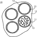
- the basic structural schematic diagram of the negative electrode active material cross section which concerns on embodiment is shown in FIG.
- the active material 10 of the embodiment has a composite structure in which a material 11 containing silicon capable of inserting and extracting lithium is covered with a carbonaceous material 12.
- the active material 10 has silicon oxide particles 11 internally containing silicon containing silicon particles 11 a in silicon oxide 11 b, and a phase 13 in which a silicate compound and a conductive additive are mixed.
- the phase 13 in which the silicate compound and the conductive additive are mixed covers at least a part of the silicon oxide particles 11 having silicon therein. These single particles or a plurality of particles are further coated with the carbonaceous material 12.
- the phase 13 in which the silicate compound and the conductive aid are mixed is present between the silicon oxide particle 11 and the carbonaceous material 12 each having silicon therein.
- the average primary particle size of the active material 10 is preferably in the range of 0.1 ⁇ m to 50 ⁇ m.
- the average primary particle size is smaller than 0.1 ⁇ m, the specific surface area is increased, and accordingly, when forming an electrode, a large amount of binder is required.
- the average primary particle size is larger than 50 ⁇ m, an unintended space is easily formed when the electrode is formed, resulting in a decrease in capacity per volume.
- coarse particles are an obstacle in the coating process. More preferably, it is 0.2 ⁇ m or more and 20 ⁇ m or less. In order to obtain the active material 10 of this size, for example, the particles once combined can be obtained by crushing and classification.
- the size of the silicon particles 11a contained in the silicon oxide 11b is preferably 2 nm or more and 150 nm or less. When 2 nm or less is difficult in manufacture, and when it becomes 150 nm or more, pulverization is easily caused by repetition of charge and discharge.
- the average primary particle size of the active material 10 is a diagonal of the field of view when observed at a magnification of 20000 or more with a scanning electron microscope (SEM: scanning electron microscopy) or a transmission electron microscope (TEM: transmission electron microscopy) Twenty or more particles present on the top can be selected and determined as their average diameter.
- the particle size refers to the average value of the major axis and minor axis of one particle in a two-dimensional image.
- the silicon particles 11a may be crystalline or amorphous, or a mixture thereof. In addition, trace elements such as phosphorus and boron may be contained therein.
- the silicon particles 11 a cause a volume change each time lithium is repeatedly stored and released, which may cause the active material to collapse. Therefore, it is preferable that the size is fine.
- the average diameter of the silicon particles 11a can be measured by the same method as the average primary particle size of the active material.
- the silicon particles 11a may be in a structure surrounded by the silicon oxide 11b, that is, the silicon particles 11a may be included in the silicon oxide 11b.
- the particles 11 having the silicon particles 11 a in the silicon oxide 11 b can be produced, for example, by disproportionation treatment of silicon oxide particles such as silicon monoxide.
- the production method is not limited to this, and silicon particles and silicon oxide particles may be produced by mixing them in a mechanochemical. As a method that can be synthesized more homogeneously and more easily, disproportionation by heat treatment is more preferable.
- the average primary particle size of the silicon oxide particles 11 having silicon therein is preferably in the range of 0.1 ⁇ m to 10 ⁇ m. When the cycle characteristics are considered, when the average primary particle diameter is in this range, there is no significant deterioration, and stable charge and discharge characteristics can be obtained.
- a mixed phase 13 of a silicate compound and a conductive auxiliary agent which is a coating layer of silicon oxide 11 having silicon particles inside, is reactive against lithium and does not cause volume expansion during charge and discharge. Is preferred.
- the silicate compound is a composite oxide of an oxide containing at least one selected from an alkaline earth element, a transition metal element, and a rare earth element and a silicon oxide.
- silicate compounds include MgSiO 3 , Mg 2 SiO 4 , TiSiO 4 , Mn 2 SiO 4 , FeSiO 3 , Fe 2 SiO 4 , Co 2 SiO 4 , Ni 2 SiO 4 , Al 2 SiO 5 , ZrSiO 4 , Y 2 SiO 5 , Y 2 Si 2 O 7 or the like.
- a silicate compound is also insulating, it is preferable to mix and use a conductive auxiliary as a mixed phase.
- the conductive aid is preferably a carbonaceous material or silicon carbide or a mixture thereof.
- the carbonaceous material includes graphite, hard carbon, soft carbon, amorphous carbon or acetylene black.
- the mixing ratio of the silicate compound to the conductive aid is typically 10:90 (mass) to 90:10 (mass).
- the conductive aid may be particulate or fibrous, or may be an amorphous phase having no particle form.
- the ratio of the amount of the conductive additive gradually increases from the surface portion of the silicon oxide particle 11 having silicon particles inside to the carbonaceous material coated layer 12 It does not matter if it has a gradient composition.
- the silicate compound and the conductive aid can be confirmed by observation by TEM and composition analysis by TEM-EDX.
- the point analysis is performed at at least three points in the boundary layer between the silicon particles or the silicon oxide particles having silicon internally and the surrounding carbonaceous matter, and the elemental components contained therein can be checked to confirm the presence of the silicate compound.
- the presence of carbonaceous material in the compound phase can also be examined.
- the carbonaceous material 12 is preferably in an amorphous phase.
- carbon materials such as highly crystalline graphite, carbon nanofibers and carbon nanotubes, and fine particles such as acetylene black may be contained. Further, fine pores of about 10 nm to 10 ⁇ m may be included.
- the carbonaceous material 12 containing silicon oxide 11 having silicon therein is at least one selected from graphite, hard carbon, soft carbon, amorphous carbon, acetylene black and the like, preferably only hard carbon, or graphite and hard carbon Mixture of is good.
- Graphite is preferable in terms of enhancing the conductivity of the active material and improving the capacity, and hard carbon has a large effect of covering the entire active material and relaxing expansion and contraction.
- the ratio of silicon or silicon oxide having silicon inside is preferably 20% by mass or more and 75% by mass or less. If it is less than 20% by mass, the effect of using silicon as a high capacity active material is small, and if it is more than 75%, it is difficult to secure conductivity and the cycleability is greatly reduced.
- the proportion of silicon or silicon oxide having silicon inside in the active material can be determined by conducting the following analysis on the complex present when the electrode cross section is cut off. Observation is performed at a magnification of 20000 times or more to determine the ratio of the area of the complex and the area of silicon or / and silicon oxide particles present inside. Next, using a density of silicon particles of 2.3 g / cm 3 , a density of silicon oxide (silicon dioxide) 2.2 g / cm 3 , and a density of hard carbon representative of a carbonaceous material of 1.8 g / cm 3 , The proportion of silicon or silicon oxide having silicon inside that is present in the composite (carbonaceous material) is estimated.
- the silicon oxide particle 11 having silicon particles inside may have a structure in which it is directly replaced by silicon particles 21 not containing the silicon oxide particles 11 b as shown in FIG.
- the active material in this case has a phase containing silicon particles 21, a carbonaceous material 12 containing silicon particles 21, and a silicate compound and a conductive additive between silicon and carbonaceous materials.
- the active material using the silicon particles 21 may be a single substance or an active material in which the silicon oxide particles 11 having the silicon particles inside as shown in FIG. 2 and the silicon particles 21 are combined.
- the composite form of the coating of the mixed phase of the silicate compound of the silicon oxide particle having the silicon particle inside and the conductive aid as shown in FIG. 1 and the composite form of the coating with the carbonaceous material is the final form
- the disproportionation timing may be at the time of coating with carbon, which will be described later.
- silicon particles may be used instead of silicon oxide particles having silicon particles inside . The following description will be made on the premise of using silicon oxide particles having silicon particles in the inside, but also in the case of using silicon particles, since the active material can be produced by the same method, common production Description of the method is omitted.
- a coating layer of fine-sized oxide particles or oxide precursor is formed as a precursor of a silicate compound around silicon oxide particles having silicon particles as a raw material inside.
- cover it contains at least 1 type chosen from an alkaline earth element, a transition metal element, and rare earth elements.
- the average primary particle size of the fine-sized oxide particles is preferably, for example, 5 nm or more and 50 nm or less.
- the average primary particle size of the oxide precursor particles is preferably, for example, 2 nm or more and 30 nm or less.
- a metal salt solution method, a sol-gel method, etc. can be used for coating of a silicate compound precursor.
- the method is not limited to this. However, it is preferable to use a method capable of forming fine particles so that the oxide formed around the silicon oxide particles is as highly reactive as possible. In addition, since the formation of a large thickness affects the charge / discharge characteristics such as the decrease in capacity, a method capable of forming a thin film is preferable.
- a precursor of a silicate compound When a precursor of a silicate compound is formed around a silicon oxide particle having silicon particles therein, the precursor may be formed to be mixed with particles serving as a conductive aid or a carbon precursor.
- a particle or a carbon precursor to be a conductive aid is made a silicate compound precursor in the same manner as the precursor of the silicate compound. It may be formed or coated around silicon oxide particles having internally coated silicon particles.
- the mixing and stirring process of a precursor of a silicate compound and a silicon oxide particle having a silicon particle inside or a precursor of a silicate compound and a particle serving as a conductive aid or a carbon precursor and a silicon oxide particle having a silicon particle inside For example, various stirring devices, ball mills, bead mill devices, and combinations thereof can be used.
- the mixing of the silicon oxide particles having silicon particles inside and the oxide precursor may be carried out by liquid phase mixing in a liquid using a dispersion medium.
- An organic solvent, water, etc. can be used as a dispersion medium.
- a spray dry method or the like may be used.
- the material to be treated that has been subjected to the mixing and stirring process is dried and heat-treated.
- the oxide precursor is oxidized, and the formed oxide is reacted with the silicon oxide to synthesize a silicate compound.
- the material to be treated which has been subjected to the mixing and stirring process is dried and heat treated to react the oxide with the silicon oxide to synthesize a silicate compound.
- the temperature of the heat treatment varies depending on the oxide and the silicate compound to be formed, and it is preferable to carry out at an appropriate temperature suitable for each.
- the mixed phase of the silicate compound and the conductive additive may cover a part of the particles, the whole, or a plurality of particles collectively, but the silicon particles may be contained inside.
- a coating phase consisting of a mixture of a silicate compound and a conductive aid can be formed around silicon oxide particles having silicon particles inside.
- the heat treatment temperature is not particularly limited, but 900 ° C. or less is preferable. When the temperature is higher than 900 ° C., disproportionation reaction of silicon oxide also occurs simultaneously. Considering the subsequent heat treatment step in the complexing treatment with carbon coating, it is not preferable that the silicon particles once precipitated grow more than necessary, so at this stage at a temperature below the disproportionation temperature It is more preferable to do.
- the heat treatment temperature may be the same temperature condition as silicon oxide particles having silicon particles inside.
- silicon oxide particles having silicon particles coated with a mixed phase of a silicate compound and a conductive auxiliary agent are incorporated in a carbonaceous material to form a composite.
- the coating with the carbonaceous material may be for silicon oxide particles having a single silicon particle inside, or may be simultaneously containing silicon oxide particles having a plurality of silicon particles inside. At this time, part of silicon oxide particles having silicon particles inside may be exposed on the surface of the carbonaceous material phase.
- a composite of a silicon particle coated with a mixed phase of a silicate compound and a conductive aid with a carbonaceous material silicon particles coated with the mixed phase of the silicate compound and the conductive aid instead of the silicon oxide particles having the silicon particles covered by the mixed phase of the silicate compound and the conductive aid.
- It may be a complex with a carbonaceous material.
- the carbonaceous material phase acts as a buffer phase that relieves stress due to volume expansion, and it is possible to prevent pulverization and dropping of the active material.
- the carbonaceous material phase is also a good conductive agent, it greatly contributes to the improvement of charge and discharge capacity and charge and discharge efficiency.
- composition processing Next, a method of coating / compositing a silicon oxide particle having silicon particles or silicon particles coated by a mixed phase of a silicate compound and a conductive additive with a carbonaceous material will be described.
- the silicon oxide particles have already become silicon oxide particles having silicon particles therein at this point.
- mixed phase-coated silicon particles or mixed phase-coated silicon oxide particles and an organic material composed of a carbon precursor are mixed, compounded and carbonized.
- the composite particles may contain carbonaceous matter itself.
- the organic material at least one of carbon materials such as graphite, coke, low-temperature fired carbon, pitch and the like, and carbon material precursors can be used.
- carbon materials such as graphite, coke, low-temperature fired carbon, pitch and the like, and carbon material precursors
- carbon material precursors since what is melted by heating, such as pitch, is melted during mechanical milling and composite formation does not proceed well, it is preferable to use it by mixing with coke, graphite, etc. which does not melt.
- Carbonaceous materials such as graphite, hard carbon, soft carbon, amorphous carbon and acetylene black may be further added to the organic material.
- the method of complexing by mixing and stirring in the liquid phase will be described below.
- the mixing and stirring process can be performed by, for example, various stirring devices, a ball mill, a bead mill device, and a combination thereof.
- the complexing of the silicon oxide particles and the carbon precursor and the carbon material internally having silicon particles or silicon particles coated with the mixed phase of the silicate compound and the conductive aid is liquid phase mixing in a liquid using a dispersion medium Good to do. It is for making it distribute more uniformly.
- a dispersion medium Good to do It is for making it distribute more uniformly.
- an organic solvent, water, etc. can be used as the dispersion medium, it is preferable to use a liquid having a good affinity to both the silicon oxide particles and the organic material having a silicate compound, silicon particles and silicon particles inside.
- Specific examples include ethanol, acetone, isopropyl alcohol, methyl ethyl ketone, ethyl acetate, N-methyl pyrrolidone (N
- the carbon precursor is soluble in the liquid or the dispersion medium in the mixing step in order to uniformly mix the silicon particles or the silicon oxide particles having the silicon particles inside by the mixed phase of the silicate compound and the conductive additive.
- these are liquid and easily polymerizable monomers or oligomers.
- organic materials such as furan resin, xylene resin, ketone resin, amino resin, melamine resin, urea resin, aniline resin, urethane resin, polyimide resin, polyester resin, phenol resin, resole resin, polyvinyl alcohol, sucrose and the like can be mentioned.
- the materials mixed in the liquid phase undergo solidification or drying steps, and are finally fired to form a composite.
- Carbonization baking is performed under inert atmosphere, such as Ar.
- the atmosphere is not limited to this, and may be a mixed atmosphere such as Ar containing hydrogen.
- the silicate compound-coated silicon particles or silicon oxide particles complexed with the organic material are heat treated to carbonize.
- the temperature of the carbonization and firing is preferably 900 ° C. or more and 1200 ° C. or less. With respect to silicon oxide particles, carbonization treatment and disproportionation reaction may simultaneously occur at this stage.
- the carbon firing is performed at a temperature between 1050 ° C. and 1200 ° C.
- a reaction of forming a silicon carbide phase may occur in the portion where the silicon particles and the carbonaceous matter are in direct contact with each other. Since silicon carbide is electrically conductive, it is preferable to be present appropriately. However, if the temperature is higher than 1200 ° C., siliconization proceeds more than necessary, and the charge / discharge capacity may be greatly reduced, which is not preferable.
- the firing temperature is preferably 1200 ° C. or less.
- the firing time is preferably in the range of about 10 minutes to 12 hours.
- the negative electrode active material according to the present embodiment can be obtained by the synthesis method as described above.
- the product after carbonization and firing may be adjusted in particle size, specific surface area and the like using various mills, pulverizers, grinders and the like.
- the second embodiment includes a negative electrode mixture layer 101 and a current collector 102, as shown in the cross-sectional view of FIG.
- the negative electrode mixture layer 101 is a layer of a mixture including an active material disposed on the current collector 102.
- the negative electrode mixture layer 101 includes a negative electrode active material 103, a conductive agent 104, and a binder 105.
- the binder 105 joins the negative electrode mixture layer 101 and the current collector.
- the negative electrode mixture layer 101 is formed on one side or both sides of the current collector 102.
- the thickness of the negative electrode mixture layer 101 is preferably in the range of 10 ⁇ m to 150 ⁇ m. Therefore, when the negative electrode current collector is supported on both sides, the total thickness of the negative electrode mixture layer 101 is in the range of 20 ⁇ m to 300 ⁇ m. A more preferable range of the thickness on one side is 10 ⁇ m or more and 100 ⁇ m or less. Within this range, the large current discharge characteristics and the cycle life are significantly improved.
- the compounding ratio of the negative electrode active material 103, the conductive agent 104, and the binder 105 in the negative electrode mixture layer 101 is 57% by mass to 95% by mass of the negative electrode active substance 103, and 3% by mass to 20% by mass of the conductive agent 104
- the binder 105 is preferably in the range of 2% by mass to 40% by mass in order to obtain good large current discharge characteristics and cycle life.
- the current collector 102 of the embodiment is a conductive member that bonds with the negative electrode mixture layer 101.
- a porous conductive substrate or a non-porous conductive substrate can be used as the current collector 102.
- These conductive substrates can be formed of, for example, copper, stainless steel or nickel.
- the thickness of the current collector is desirably 5 ⁇ m or more and 20 ⁇ m or less. Within this range, a balance between electrode strength and weight reduction can be achieved.
- the negative electrode active material 103 it is preferable to use the active materials 10 and 20 of the first embodiment.
- the negative electrode mixture layer 101 may contain a conductive agent 104.
- the conductive agent 104 include acetylene black, carbon black, and graphite.
- the negative electrode mixture layer 101 may contain a binder 105 that binds negative electrode materials.
- a binder 105 that binds negative electrode materials.
- the binding agent 105 for example, polytetrafluoroethylene (PTFE), polyvinylidene fluoride (PVdF), ethylene-propylene-diene copolymer (EPDM), styrene-butadiene rubber (SBR), polyimide, polyaramid or the like is used. be able to.
- two or more binders may be used in combination, and the binder excellent in binding between the active materials and the binder excellent in binding between the active material and the current collector When the combination of the above, the thing with high hardness, and the thing excellent in pliability are used combining, the negative electrode excellent in the lifetime characteristic can be produced.
- the non-aqueous electrolyte secondary battery according to the third embodiment is housed, for example, with a separator interposed therebetween, spatially separated from the cathode in the sheathing material, the positive electrode housed in the sheathing material, and the sheathing material.
- a negative electrode and a non-aqueous electrolyte filled in the outer package are provided.
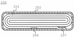
- FIG. 4 is a schematic cross-sectional view of a flat-type non-aqueous electrolyte secondary battery 200 in which the packaging material 202 is formed of a laminate film.
- the flat wound electrode group 201 is accommodated in a bag-like exterior material 202 made of a laminate film in which an aluminum foil is interposed between two resin layers.
- the flat wound electrode group 201 is laminated in the order of a negative electrode 203, a separator 204, a positive electrode 205, and a separator 204, as shown in FIG. Then, the laminate is spirally wound and formed by press molding.
- the electrode closest to the bag-like exterior material 202 is a negative electrode, and no negative electrode mixture is formed on the negative electrode current collector on the side of the exterior material 202, and the negative electrode mixture is not formed on the negative electrode current collector. It has the structure which formed the negative mix on only one side.
- the other negative electrode 203 is configured by forming a negative electrode mixture on both sides of the negative electrode current collector.
- the positive electrode 205 is configured by forming a positive electrode mixture on both sides of a positive electrode current collector.
- the negative electrode terminal is electrically connected to the negative electrode current collector of the outermost negative electrode 203
- the positive electrode terminal is electrically connected to the positive electrode current collector of the inner positive electrode 205 near the outer peripheral end of the wound electrode group 201.
- the negative electrode terminal 206 and the positive electrode terminal 207 are extended from the opening of the package 202 to the outside.
- a liquid non-aqueous electrolyte is injected from the opening of the package 202.
- the wound electrode group 201 and the liquid non-aqueous electrolyte are sealed by heat sealing the opening of the bag-like outer package 202 with the negative electrode terminal 206 and the positive electrode terminal 207 interposed therebetween.
- Examples of the negative electrode terminal 206 include aluminum or an aluminum alloy containing an element such as Mg, Ti, Zn, Mn, Fe, Cu, or Si.
- the negative electrode terminal 206 is preferably made of the same material as the negative electrode current collector in order to reduce the contact resistance with the negative electrode current collector.
- the positive electrode terminal 207 can use a material having electrical stability and conductivity in the range of 3 to 4.25 V with respect to the lithium ion metal. Specifically, an aluminum alloy containing an element such as aluminum or Mg, Ti, Zn, Mn, Fe, Cu, Si or the like can be mentioned.
- the positive electrode terminal 207 is preferably made of the same material as the positive electrode current collector in order to reduce the contact resistance with the positive electrode current collector.
- packaging material 202 the positive electrode 205, the electrolyte, and the separator 204, which are components of the non-aqueous electrolyte secondary battery 200, will be described in detail.
- Exterior material 202 is formed of a laminate film having a thickness of 0.5 mm or less. Alternatively, a metal container having a thickness of 1.0 mm or less is used as the exterior material. The metal container is more preferably 0.5 mm or less in thickness.
- the shape of the exterior material 202 can be selected from flat (thin), square, cylindrical, coin, and button.
- the exterior material include, for example, an exterior material for a small battery loaded on a portable electronic device or the like, an exterior material for a large battery loaded on a two- or four-wheeled automobile, etc. according to the battery size.
- the laminate film a multilayer film in which a metal layer is interposed between resin layers is used.
- the metal layer is preferably aluminum foil or aluminum alloy foil in order to reduce the weight.
- the resin layer for example, polymeric materials such as polypropylene (PP), polyethylene (PE), nylon, polyethylene terephthalate (PET) can be used.
- PP polypropylene
- PE polyethylene
- PET polyethylene terephthalate
- the laminated film can be molded into the shape of the exterior material by sealing by heat fusion.
- the metal container is made of aluminum or aluminum alloy or the like.
- the aluminum alloy is preferably an alloy containing an element such as magnesium, zinc or silicon.
- the alloy contains a transition metal such as iron, copper, nickel, or chromium, the amount is preferably 100 ppm by mass or less.
- the positive electrode 205 has a structure in which a positive electrode mixture containing an active material is supported on one side or both sides of a positive electrode current collector.
- the thickness of one side of the positive electrode mixture is preferably in the range of 1.0 ⁇ m or more and 150 ⁇ m or less from the viewpoint of maintaining the large current discharge characteristics of the battery and the cycle life. Therefore, when the positive electrode current collector is supported on both sides, the total thickness of the positive electrode mixture is desirably in the range of 20 ⁇ m to 300 ⁇ m. A more preferable range of one side is 30 ⁇ m or more and 120 ⁇ m or less. Within this range, the large current discharge characteristics and the cycle life are improved.
- the positive electrode mixture may contain a conductive agent in addition to the binder that binds the positive electrode active material and the positive electrode active material.
- various oxides such as manganese dioxide, lithium manganese composite oxide, lithium containing nickel cobalt oxide (for example, LiCOO 2 ), lithium containing nickel cobalt oxide (for example, LiNi 0.8 CO 0.2 O) 2 )
- a lithium manganese composite oxide for example, LiMn 2 O 4 , LiMnO 2
- LiMnO 2 lithium manganese composite oxide
- acetylene black, carbon black, graphite and the like can be mentioned.
- binder examples include, for example, polytetrafluoroethylene (PTFE), polyvinylidene fluoride (PVdF), ethylene-propylene-diene copolymer (EPDM), styrene-butadiene rubber (SBR), etc. .
- PTFE polytetrafluoroethylene
- PVdF polyvinylidene fluoride
- EPDM ethylene-propylene-diene copolymer
- SBR styrene-butadiene rubber
- the compounding ratio of the positive electrode active material, the conductive agent and the binder is 80% by mass to 95% by mass of the positive electrode active material, 3% by mass to 20% by mass of the conductive agent, and 2% by mass to 7% by mass of the binder The range is preferable in order to obtain good high current discharge characteristics and cycle life.
- a porous conductive substrate or a non-porous conductive substrate can be used as the current collector.
- the thickness of the current collector is desirably 5 ⁇ m or more and 20 ⁇ m or less. Within this range, a balance between electrode strength and weight reduction can be achieved.
- the positive electrode 205 is prepared, for example, by suspending an active material, a conductive agent, and a binder in a widely used solvent to prepare a slurry, applying the slurry to a current collector, drying it, and then applying a press. Be done.
- the positive electrode 205 may also be manufactured by forming an active material, a conductive agent, and a binder in the form of pellets to form a positive electrode layer and forming it on a current collector.
- negative electrode 203 As the negative electrode 203, the negative electrode 100 described in the second embodiment is used.
- Electrolyte A non-aqueous electrolytic solution, an electrolyte-impregnated polymer electrolyte, a polymer electrolyte, or an inorganic solid electrolyte can be used as the electrolyte.
- the non-aqueous electrolytic solution is a liquid electrolytic solution prepared by dissolving the electrolyte in a non-aqueous solvent, and is held in the void in the electrode group.
- non-aqueous solvent a non-aqueous solvent mainly composed of a mixed solvent of propylene carbonate (PC) or ethylene carbonate (EC) and a non-aqueous solvent having a viscosity lower than that of PC or EC (hereinafter referred to as second solvent) is used. Is preferred.
- the second solvent for example, chain carbon is preferable, and among them, dimethyl carbonate (DMC), methyl ethyl carbonate (MEC), diethyl carbonate (DEC), ethyl propionate, methyl propionate, methyl ⁇ -butyrolactone (BL), acetonitrile ( AN), ethyl acetate (EA), toluene, xylene or methyl acetate (MA).
- DMC dimethyl carbonate
- MEC methyl ethyl carbonate
- DEC diethyl carbonate
- EA ethyl propionate
- BL methyl ⁇ -butyrolactone
- AN acetonitrile
- EA ethyl acetate
- MA toluene
- MA methyl acetate
- the viscosity of the second solvent is preferably 2.8 cmp or less at 25 ° C.
- the blending amount of ethylene carbonate or propylene carbonate in the mixed solvent is preferably 1.0% to 80% by volume. More preferably, the blending amount of ethylene carbonate or propylene carbonate is 20% to 75% by volume.
- Examples of the electrolyte contained in the non-aqueous electrolyte include lithium perchlorate (LiClO 4 ), lithium hexafluorophosphate (LiPF 6 ), lithium borofluoride (LiBF 4 ), lithium arsenic hexafluoride (LiAsF 6 ), Lithium salts (electrolytes) such as lithium trifluorometasulfonate (LiCF 3 SO 3 ) and bis trifluoromethylsulfonylimido lithium [LiN (CF 3 SO 2 ) 2 ] can be mentioned. Among them, LiPF 6 and LiBF 4 are preferably used.
- the amount of electrolyte dissolved in the non-aqueous solvent is desirably 0.5 mol / L or more and 2.0 mol / L or less.
- the separator 204 can be used.
- the separator 204 uses a porous separator.
- a porous film containing polyethylene, polypropylene, or polyfluorinated pinylidene (PVdF), a synthetic resin non-woven fabric, or the like can be used.
- PVdF polyfluorinated pinylidene
- porous films made of polyethylene or polypropylene or both are preferable because they can improve the safety of the secondary battery.
- the thickness of the separator 204 is preferably 30 ⁇ m or less. If the thickness exceeds 30 ⁇ m, the distance between the positive and negative electrodes may be increased to increase the internal resistance.
- the lower limit of the thickness is preferably 5 ⁇ m. If the thickness is less than 5 ⁇ m, the strength of the separator 204 may be significantly reduced to cause an internal short circuit.
- the upper limit of the thickness is more preferably 25 ⁇ m, and the lower limit is more preferably 1.0 ⁇ m.
- the separator 204 preferably has a thermal shrinkage of 20% or less when placed at 120 ° C. for one hour. When the thermal contraction rate exceeds 20%, the possibility of the occurrence of a short circuit due to heating increases. The heat shrinkage rate is more preferably 15% or less.
- the separator 204 preferably has a porosity in the range of 30 to 60%. This is due to the following reasons. If the porosity is less than 30%, it may be difficult to obtain high electrolyte retention in the separator 204. On the other hand, if the porosity exceeds 60%, sufficient strength of the separator 204 may not be obtained. A more preferable range of the porosity is 35% or more and 70% or less.
- the separator 204 preferably has an air permeability of 500 seconds / 100 cm 3 or less. If the air permeability exceeds 500 seconds / 100 cm 3 , it may be difficult to obtain high lithium ion mobility in the separator 204. Further, the lower limit value of the air permeability is 30 seconds / 100 cm 3 . If the air permeability is less than 30 seconds / 100 cm 3 , sufficient separator strength may not be obtained.
- the upper limit of the air permeability is more preferably 300 seconds / 100 cm 3 , and the lower limit is more preferably 50 seconds / 100 cm 3 .
- Ceramic particles may be coated on the separator surface. This can enhance safety. Examples of the ceramic particles include Al 2 O 3 , TiO 2 and ZrO 2 .
- the battery pack according to the fourth embodiment includes one or more nonaqueous electrolyte secondary batteries (that is, single cells) according to the third embodiment.
- the battery pack includes a plurality of unit cells, the unit cells are electrically connected in series, in parallel, or in series and in parallel.
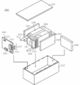
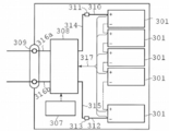
- the battery pack 300 will be specifically described with reference to the schematic view of FIG. 6 and the block diagram of FIG. In the battery pack 300 shown in FIG. 6, the non-aqueous electrolyte battery 200 shown in FIG. 4 is used as the single battery 301.
- the plurality of unit cells 301 are stacked such that the negative electrode terminal 302 and the positive electrode terminal 303 extended to the outside are aligned in the same direction, and are assembled with the adhesive tape 304 to form a battery assembly 305. These single cells 301 are electrically connected in series to each other as shown in FIG.
- the printed wiring board 306 is disposed to face the side surface of the unit cell 301 from which the negative electrode terminal 302 and the positive electrode terminal 303 extend.
- a thermistor 307, a protection circuit 308, and a current-carrying terminal 309 for an external device are mounted on the printed wiring board 306, as shown in FIG. 7, a thermistor 307, a protection circuit 308, and a current-carrying terminal 309 for an external device are mounted.
- An insulating plate (not shown) is attached to the surface of the printed wiring board 306 facing the battery assembly 305 in order to avoid unnecessary connection with the wiring of the battery assembly 305.
- the positive electrode lead 310 is connected to the positive electrode terminal 303 located in the lowermost layer of the assembled battery 305, and the tip thereof is inserted into the positive electrode connector 311 of the printed wiring board 306 and is electrically connected.
- the negative electrode lead 312 is connected to the negative electrode terminal 302 located in the uppermost layer of the assembled battery 305, and the tip thereof is inserted into the negative electrode connector 313 of the printed wiring board 306 and electrically connected.
- the connectors 311 and 313 are connected to the protective circuit 308 through the wires 314 and 315 formed on the printed wiring board 306.
- the thermistor 307 is used to detect the temperature of the single battery 305, and the detection signal is transmitted to the protection circuit 308.
- the protection circuit 308 can cut off the plus side wiring 316 a and the minus side wiring 316 b between the protection circuit 308 and the current application terminal 309 to the external device under predetermined conditions.
- the predetermined condition is, for example, when the detected temperature of the thermistor 307 becomes equal to or higher than a predetermined temperature. Further, the predetermined condition is when overcharging, overdischarging, overcurrent, etc. of the single battery 301 is detected. The detection of the overcharge and the like is performed on the individual single battery 301 or the entire single battery 301.
- the battery voltage When detecting each single battery 301, the battery voltage may be detected, or the positive electrode potential or the negative electrode potential may be detected. In the latter case, a lithium electrode used as a reference electrode is inserted into each single battery 301.
- the wires 317 for voltage detection are connected to each of the unit cells 301, and the detection signal is transmitted to the protection circuit 308 through the wires 317.
- Protective sheets 318 made of rubber or resin are respectively disposed on the three side surfaces of the assembled battery 305 except the side surfaces from which the positive electrode terminal 303 and the negative electrode terminal 302 project.
- the assembled battery 305 is stored in the storage container 319 together with each protective sheet 318 and the printed wiring board 306. That is, the protective sheet 318 is disposed on both the inner side in the long side direction of the storage container 319 and the inner side in the short side direction, and the printed wiring board 306 is disposed on the inner side opposite to the short side.
- the assembled battery 305 is located in a space surrounded by the protective sheet 318 and the printed wiring board 306.
- the lid 320 is attached to the upper surface of the storage container 319.
- a heat shrink tape may be used instead of the adhesive tape 304 for fixing the battery pack 305.
- protective sheets are disposed on both sides of the battery pack, and the heat shrinkable tape is circulated, and then the heat shrinkable tape is heat shrunk to bind the battery pack.
- FIG. 6 and FIG. 7 show a form in which the single cells 301 are connected in series, in order to increase the battery capacity, they may be connected in parallel, or the series connection and the parallel connection may be combined.
- the assembled battery packs can be further connected in series or in parallel. According to the present embodiment described above, by providing the non-aqueous electrolyte secondary battery having excellent charge and discharge cycle performance in the third embodiment, a battery pack having excellent charge and discharge cycle performance can be provided. it can.
- the aspect of the battery pack is suitably changed according to a use.
- the application of the battery pack is preferably one that exhibits excellent cycle characteristics when taking out a large current.
- examples include power supplies for digital cameras, and in-vehicle applications such as two-wheel and four-wheel hybrid electric vehicles, two- and four-wheel electric vehicles, and assist bicycles.
- a battery pack using a non-aqueous electrolyte secondary battery excellent in high temperature characteristics is suitably used for vehicles.
- Example 1 Active material composite particles were produced under the following conditions.
- a commercially available silicon monoxide particle (average particle diameter 45 ⁇ m) was ground in a ball mill to obtain a powder with an average particle diameter of 0.3 ⁇ m.
- 6 g of magnesium nitrate hexahydrate is dissolved in a mixture of 20 cc of water and ethanol to give an aqueous solution, to which 0.06 g of sucrose (C 12 H 22 O 11 ) and 4 g of the ground silicon monoxide powder are added, and a magnet stirrer Mixed for 1 hour.
- the liquid mixture is dried using an evaporator and further vacuum dried at 100 ° C.
- the obtained powder is recovered, placed in an electric furnace, heated to 150 ° C.
- Silicon monoxide particles coated with carbon dioxide precursors were prepared.
- heat treatment was continuously performed at 700 ° C. for one hour in an argon gas atmosphere.
- silicon monoxide particles (including a silicate compound) coated with an oxide and a carbonaceous material were obtained.
- silicon monoxide particles coated with oxide and carbonaceous material were complexed with hard carbon according to the following procedure.
- 4 g of coated silicon monoxide particles and 0.3 g of graphite powder were added to a mixture of 5 g of furfuryl alcohol and 10 g of ethanol, and mixed by a planetary ball mill to prepare a slurry.
- the obtained slurry was filtered to remove balls, 0.5 g of dilute hydrochloric acid as a polymerization catalyst for furfuryl alcohol was added, and left at room temperature to dry and solidify to obtain a carbon composite precursor.
- the obtained carbon composite precursor is placed in an electric furnace, calcined at 1000 ° C. for 2 hours in an Ar gas atmosphere, cooled to room temperature, pulverized using a mortar, and passed through a sieve of 20 ⁇ m mesh to make a negative electrode active material composite. Obtained a powder.
- a mixture of 0.1 g of graphite powder having an average particle diameter of 3 ⁇ m was mixed with 0.6 g of the obtained negative electrode active material composite powder, mixed with a solution prepared with N-methylpyrrolidone dispersion medium so as to be polyimide 16% by mass, Used to mix.
- the obtained paste-like slurry was applied onto a copper foil with a thickness of 12 ⁇ m and pressed, and then heat treated in Ar gas at 400 ° C. for 2 hours.
- the potential difference between the reference electrode and the test electrode is charged at a constant current of 6 mA to 0.01 V, then charged at a constant voltage, and then discharged to 1.5 V at a constant current of 6 mA. This cycle is repeated 30 times.
- the ratio of the 30th discharge capacity to the 1st discharge capacity of the charge and discharge was defined as the discharge capacity retention ratio.
- Example 1 The results of Examples and Comparative Examples are summarized in Table 1 below. For the following examples and comparative examples, only portions different from those in Example 1 will be described, and the other synthesis and evaluation procedures are the same as in Example 1 and thus the description will be omitted.
- Example 2 A sample was prepared in the same manner as in Example 1 except that the heat treatment temperature for carbon complexation was set to 1100 ° C., and a charge and discharge test was performed in the same manner as in Example 1 by electrode formation.
- Example 3 A sample was prepared in the same manner as in Example 1 except that 14 g of aluminum nitrate nonahydrate was used in place of the magnesium nitrate salt, was made into an electrode, and a charge / discharge test was performed in the same manner as in Example 1. .
- Example 4 A sample was prepared in the same manner as in Example 1 except that 8 g of iron nitrate nonahydrate was used in place of the magnesium nitrate salt, was made into an electrode, and a charge / discharge test was performed in the same manner as in Example 1. .
- Example 5 A sample was prepared in the same manner as in Example 1 except that 4 g of zirconium oxynitrate dihydrate was used in place of the magnesium nitrate salt, was used as an electrode, and a charge / discharge test was performed in the same manner as in Example 1.
- 4 g of zirconium oxynitrate dihydrate was used in place of the magnesium nitrate salt, was used as an electrode, and a charge / discharge test was performed in the same manner as in Example 1.
- Example 6 Using a silicon powder having an average particle diameter of 40 nm instead of the silicon monoxide powder, the magnesium oxide and the carbon material are coated in the same manner as in Example 1, 1 g of the coated silicon particles, 3.2 g of furfuryl alcohol and 10 g of ethanol The mixture was mixed to form a slurry, and then similarly composited to form a negative electrode active material. Using this active material, an electrode was formed in the same manner as in Example 1, and a charge / discharge test was performed in the same manner as in Example 1.
- Example 1 Samples were prepared in the same manner as in Example 1 except that the silicon monoxide oxide particles pulverized in the same manner as in Example 1 were directly treated with a carbonaceous material without being coated with an oxide and a carbonaceous material. Then, the battery was made into an electrode, and the charge and discharge test was conducted in the same manner as in Example 1.
- Example 2 A sample was prepared in the same manner as in Example 6 except that the magnesium oxide coating was not performed, and after being made into an electrode, a charge / discharge test was performed.
- Example 2 in which the temperature of the complexing heat treatment was 1100 ° C., it was revealed that silicon particles were partially siliconized.
- the silicon carbide formed by partial disproportionation caused silicon carbide to slightly reduce the capacity, but it hardly affected the initial charge and discharge efficiency, and the life was also improved.
- the charge and discharge efficiency of the first time is achieved by having the phase containing the silicate compound and the conductive auxiliary agent formed by the reaction around the silicon oxide containing silicon, and further covering and compounding with the carbonaceous substance around the phase. It is found that the conductive path during the cycle is maintained and the cycle life is improved.
- Sack-like packaging material 203 negative electrode 204: separator 205: positive electrode 300: battery pack 301: cell 302: negative electrode terminal 303: positive electrode terminal 304: adhesive tape 305: battery combination 306: 306 Printed wiring board 307: Thermistor 308: Protection circuit 309: Conduction terminal 310: Positive electrode side lead 311: Positive electrode side connector 312: Negative electrode side lead 313: Negative electrode side connector 3 4 ... wire, 315 ... wire, 316a ... plus side wiring, 316b ... minus side wiring, 317 ... wire, 318 ... protective sheet, 319 ... receiving container, 320 ... lid
Landscapes
- Chemical & Material Sciences (AREA)
- Chemical Kinetics & Catalysis (AREA)
- Electrochemistry (AREA)
- General Chemical & Material Sciences (AREA)
- Engineering & Computer Science (AREA)
- Inorganic Chemistry (AREA)
- Materials Engineering (AREA)
- Manufacturing & Machinery (AREA)
- Composite Materials (AREA)
- Battery Electrode And Active Subsutance (AREA)
Abstract
Le problème à résoudre dans le cadre de l'invention consiste à fournir un matériau actif d'électrode négative pour une pile à électrolyte non aqueux présentant une efficacité de charge/décharge initiale élevée et des caractéristiques de cycle exceptionnelles. La solution consiste, selon un mode de réalisation, en un matériau actif d'électrode négative destiné à une pile rechargeable à électrolyte non aqueux et comportant du silicium ou de l'oxyde de silicium contenant du silicium, un matériau carboné renfermant le silicium ou l'oxyde de silicium contenant du silicium, et une phase contenant un composé de silicate et une aide électroconductrice présente entre le matériau carboné et le silicium ou l'oxyde de silicium contenant du silicium.
Priority Applications (3)
| Application Number | Priority Date | Filing Date | Title |
|---|---|---|---|
| JP2016509626A JP6430489B2 (ja) | 2014-03-24 | 2014-03-24 | 非水電解質電池用負極活物質、非水電解質二次電池用負極、非水電解質二次電池及び電池パック |
| PCT/JP2014/057971 WO2015145521A1 (fr) | 2014-03-24 | 2014-03-24 | Matériau actif d'électrode négative pour une pile à électrolyte non aqueux, électrode négative pour une pile rechargeable à électrolyte non aqueux, pile rechargeable à électrolyte non aqueux, et bloc-piles |
| US15/255,720 US10511026B2 (en) | 2014-03-24 | 2016-09-02 | Electrode for nonaqueous electrolyte secondary battery, nonaqueous electrolyte secondary battery, battery pack, and vehicle |
Applications Claiming Priority (1)
| Application Number | Priority Date | Filing Date | Title |
|---|---|---|---|
| PCT/JP2014/057971 WO2015145521A1 (fr) | 2014-03-24 | 2014-03-24 | Matériau actif d'électrode négative pour une pile à électrolyte non aqueux, électrode négative pour une pile rechargeable à électrolyte non aqueux, pile rechargeable à électrolyte non aqueux, et bloc-piles |
Related Child Applications (1)
| Application Number | Title | Priority Date | Filing Date |
|---|---|---|---|
| US15/255,720 Continuation US10511026B2 (en) | 2014-03-24 | 2016-09-02 | Electrode for nonaqueous electrolyte secondary battery, nonaqueous electrolyte secondary battery, battery pack, and vehicle |
Publications (1)
| Publication Number | Publication Date |
|---|---|
| WO2015145521A1 true WO2015145521A1 (fr) | 2015-10-01 |
Family
ID=54194123
Family Applications (1)
| Application Number | Title | Priority Date | Filing Date |
|---|---|---|---|
| PCT/JP2014/057971 Ceased WO2015145521A1 (fr) | 2014-03-24 | 2014-03-24 | Matériau actif d'électrode négative pour une pile à électrolyte non aqueux, électrode négative pour une pile rechargeable à électrolyte non aqueux, pile rechargeable à électrolyte non aqueux, et bloc-piles |
Country Status (3)
| Country | Link |
|---|---|
| US (1) | US10511026B2 (fr) |
| JP (1) | JP6430489B2 (fr) |
| WO (1) | WO2015145521A1 (fr) |
Cited By (43)
| Publication number | Priority date | Publication date | Assignee | Title |
|---|---|---|---|---|
| JP2015230792A (ja) * | 2014-06-04 | 2015-12-21 | 日立化成株式会社 | リチウムイオン二次電池用導電材料、リチウムイオン二次電池負極形成用組成物、リチウムイオン二次電池正極形成用組成物、リチウムイオン二次電池用負極、リチウムイオン二次電池用正極及びリチウムイオン二次電池 |
| WO2018179969A1 (fr) * | 2017-03-29 | 2018-10-04 | パナソニックIpマネジメント株式会社 | Matériau d'électrode négative pour batterie secondaire à électrolytique non aqueux et batterie secondaire à électrolyte non aqueux |
| EP3343677A4 (fr) * | 2016-06-02 | 2019-02-27 | LG Chem, Ltd. | Matériau cathode actif, cathode le comprenant et batterie secondaire au lithium comprenant ce même matériau |
| US10290864B2 (en) | 2016-04-07 | 2019-05-14 | StoreDot Ltd. | Coated pre-lithiated anode material particles and cross-linked polymer coatings |
| US10293704B2 (en) | 2014-04-08 | 2019-05-21 | StoreDot Ltd. | Electric vehicles with adaptive fast-charging, utilizing supercapacitor-emulating batteries |
| WO2019108050A1 (fr) * | 2017-12-01 | 2019-06-06 | 대주전자재료 주식회사 | Matériau actif d'anode pour batterie rechargeable à électrolyte non aqueux comprenant un composite à base d'oxyde de silicium et son procédé de production |
| KR20190065182A (ko) * | 2017-12-01 | 2019-06-11 | 대주전자재료 주식회사 | 규소산화물복합체를 포함하는 비수전해질 이차전지용 음극활물질 및 이의 제조방법 |
| KR20190066596A (ko) * | 2017-12-05 | 2019-06-13 | 대주전자재료 주식회사 | 비수전해질 이차전지용 음극활물질 및 이의 제조 방법 |
| WO2019112325A1 (fr) * | 2017-12-05 | 2019-06-13 | 대주전자재료 주식회사 | Matériau actif d'électrode négative pour batterie secondaire à électrolyte non aqueux et procédé de production correspondant |
| US10355271B2 (en) | 2016-04-07 | 2019-07-16 | StoreDot Ltd. | Lithium borates and phosphates coatings |
| US10367193B2 (en) | 2016-04-07 | 2019-07-30 | StoreDot Ltd. | Methods of preparing anodes using tin as active material |
| US10367192B2 (en) | 2016-04-07 | 2019-07-30 | StoreDot Ltd. | Aluminum anode active material |
| WO2019151813A1 (fr) * | 2018-01-31 | 2019-08-08 | 주식회사 엘지화학 | Matériau actif d'anode, anode comprenant ce dernier et batterie rechargeable au lithium |
| WO2019151778A1 (fr) * | 2018-01-30 | 2019-08-08 | 주식회사 엘지화학 | Matériau actif d'anode destiné à une batterie secondaire au lithium, anode le comprenant, et batterie secondaire au lithium-ion comprenant une telle anode |
| WO2019151814A1 (fr) * | 2018-01-31 | 2019-08-08 | 주식회사 엘지화학 | Matériau actif d'anode, anode le comprenant, et batterie secondaire au lithium |
| US10424785B2 (en) | 2016-06-27 | 2019-09-24 | Panasonic Intellectual Property Management Co., Ltd. | Negative electrode material including composite particles, and method for producing the same |
| US10424814B2 (en) | 2016-04-07 | 2019-09-24 | StoreDot Ltd. | Introducing a mobile layer of ionic liquid into electrolytes of lithium ion batteries |
| JP2019169354A (ja) * | 2018-03-23 | 2019-10-03 | 三洋電機株式会社 | 非水電解質二次電池用負極及び非水電解質二次電池 |
| US10454101B2 (en) | 2017-01-25 | 2019-10-22 | StoreDot Ltd. | Composite anode material made of core-shell particles |
| US10468727B2 (en) * | 2016-04-07 | 2019-11-05 | StoreDot Ltd. | Graphite-carbohydrate active material particles with carbonized carbohydrates |
| US10549650B2 (en) | 2014-04-08 | 2020-02-04 | StoreDot Ltd. | Internally adjustable modular single battery systems for power systems |
| US10608463B1 (en) | 2019-01-23 | 2020-03-31 | StoreDot Ltd. | Direct charging of battery cell stacks |
| CN110959207A (zh) * | 2017-12-22 | 2020-04-03 | 珍拉布斯能源有限公司 | 实现高容量、高能量密度和长循环寿命性能的锂离子电池的具有硅氧化物活性材料的电极 |
| WO2020129652A1 (fr) * | 2018-12-21 | 2020-06-25 | パナソニックIpマネジメント株式会社 | Matériau actif d'électrode négative pour batteries secondaires, et batterie secondaire |
| US10818919B2 (en) | 2016-04-07 | 2020-10-27 | StoreDot Ltd. | Polymer coatings and anode material pre-lithiation |
| JP2020202068A (ja) * | 2019-06-10 | 2020-12-17 | 昭和電工マテリアルズ株式会社 | リチウムイオン二次電池用負極活物質、リチウムイオン二次電池およびリチウムイオン二次電池用負極活物質の製造方法 |
| US10873200B2 (en) | 2016-12-15 | 2020-12-22 | StoreDot Ltd. | Devices and methods comprising supercapacitor-emulating fast-charging batteries |
| KR20200144855A (ko) * | 2019-06-19 | 2020-12-30 | 대주전자재료 주식회사 | 리튬 이차전지 음극재용 탄소-규소복합산화물 복합체 및 이의 제조방법 |
| JPWO2021020226A1 (fr) * | 2019-07-31 | 2021-02-04 | ||
| US10916811B2 (en) | 2016-04-07 | 2021-02-09 | StoreDot Ltd. | Semi-solid electrolytes with flexible particle coatings |
| JPWO2021153076A1 (fr) * | 2020-01-31 | 2021-08-05 | ||
| US11128152B2 (en) | 2014-04-08 | 2021-09-21 | StoreDot Ltd. | Systems and methods for adaptive fast-charging for mobile devices and devices having sporadic power-source connection |
| JPWO2021200343A1 (fr) * | 2020-03-30 | 2021-10-07 | ||
| JPWO2021241618A1 (fr) * | 2020-05-29 | 2021-12-02 | ||
| US11205796B2 (en) | 2016-04-07 | 2021-12-21 | StoreDot Ltd. | Electrolyte additives in lithium-ion batteries |
| US20210399288A1 (en) * | 2018-10-12 | 2021-12-23 | Albemarle Corporation | Particles comprising silicon and lithium |
| JP2022517702A (ja) * | 2019-12-26 | 2022-03-10 | 寧徳新能源科技有限公司 | 負極材料、並びにそれを含む電気化学的装置及び電子設備 |
| WO2022092273A1 (fr) * | 2020-10-30 | 2022-05-05 | パナソニックIpマネジメント株式会社 | Batterie rechargeable à électrolyte non aqueux |
| JP2022530780A (ja) * | 2019-04-29 | 2022-07-01 | デジュ・エレクトロニック・マテリアルズ・カンパニー・リミテッド | リチウム二次電池負極材用シリコン複合酸化物及びその製造方法 |
| WO2023053631A1 (fr) * | 2021-09-30 | 2023-04-06 | 三洋電機株式会社 | Matériau actif d'électrode négative pour batterie secondaire à électrolyte non aqueux, et batterie secondaire à électrolyte non aqueux |
| WO2023199543A1 (fr) * | 2022-04-13 | 2023-10-19 | パナソニックIpマネジメント株式会社 | Particules de matériau actif composite, batterie et procédé de production de particules de matériau actif composite |
| US11831012B2 (en) | 2019-04-25 | 2023-11-28 | StoreDot Ltd. | Passivated silicon-based anode material particles |
| JP2024077629A (ja) * | 2022-11-28 | 2024-06-07 | ハンソル ケミカル カンパニー リミテッド | 負極活物質、その製造方法、及びこれを含むリチウム二次電池 |
Families Citing this family (20)
| Publication number | Priority date | Publication date | Assignee | Title |
|---|---|---|---|---|
| KR102220905B1 (ko) * | 2016-09-23 | 2021-02-26 | 삼성에스디아이 주식회사 | 리튬이차전지용 음극 활물질 및 이를 포함한 음극을 함유한 리튬이차전지 |
| KR101960855B1 (ko) * | 2017-03-20 | 2019-03-21 | 대주전자재료 주식회사 | 리튬 이차전지 음극재용 실리콘 복합산화물 및 이의 제조방법 |
| KR20190027188A (ko) | 2017-09-06 | 2019-03-14 | 삼성에스디아이 주식회사 | 리튬 이차 전지용 비수 전해질 및 이를 포함하는 리튬 이차 전지 |
| KR102449844B1 (ko) * | 2017-09-06 | 2022-09-29 | 삼성에스디아이 주식회사 | 리튬 이차 전지 |
| KR102244953B1 (ko) * | 2017-11-09 | 2021-04-27 | 주식회사 엘지화학 | 음극 활물질, 상기 음극 활물질을 포함하는 음극, 및 상기 음극을 포함하는 이차 전지 |
| CN110915033B (zh) * | 2017-12-01 | 2022-06-07 | 株式会社Lg化学 | 用于锂二次电池的负极和包括该负极的锂二次电池 |
| US11283068B2 (en) * | 2019-12-20 | 2022-03-22 | Enevate Corporation | Electrochemically active materials and methods of preparing the same |
| WO2019151774A1 (fr) * | 2018-01-30 | 2019-08-08 | 주식회사 엘지화학 | Matériau actif d'anode, procédé de préparation de matériau actif d'anode, anode comprenant un matériau actif d'anode et batterie secondaire comprenant l'anode |
| KR102260425B1 (ko) * | 2018-05-24 | 2021-08-02 | 주식회사 엘지에너지솔루션 | 리튬 이차전지용 음극활물질 및 이의 제조방법 |
| KR102691451B1 (ko) * | 2018-12-13 | 2024-08-05 | 삼성전자주식회사 | 음극 활물질 및 이를 채용한 리튬 이차 전지, 및 상기 음극 활물질의 제조방법 |
| KR102682363B1 (ko) * | 2019-01-18 | 2024-07-04 | 주식회사 엘지에너지솔루션 | 리튬이차전지용 음극 활물질 및 이를 포함한 리튬이차전지 |
| EP4099439A4 (fr) * | 2020-01-31 | 2024-03-20 | Panasonic Intellectual Property Management Co., Ltd. | Particules de matière active ainsi que procédé de fabrication de celles-ci, élément électrochimique ainsi que procédé de fabrication de celui-ci, et dispositif électrochimique |
| JP7656831B2 (ja) | 2020-01-31 | 2025-04-04 | パナソニックIpマネジメント株式会社 | 電気化学素子およびその製造方法、ならびに電気化学デバイス |
| KR102590434B1 (ko) * | 2020-09-11 | 2023-10-18 | 주식회사 엘지에너지솔루션 | 음극 활물질, 상기 음극 활물질을 포함하는 음극, 및 상기 음극을 포함하는 이차 전지 |
| KR20220091672A (ko) * | 2020-12-23 | 2022-07-01 | 대주전자재료 주식회사 | 다공성 규소 구조체, 이를 포함하는 다공성 규소-탄소 복합체 및 음극 활물질 |
| CN113725409A (zh) * | 2021-07-29 | 2021-11-30 | 合肥国轩高科动力能源有限公司 | 一种硅基负极材料及其制备方法 |
| EP4250399A4 (fr) * | 2021-08-13 | 2025-06-11 | LG Energy Solution, Ltd. | Matériau actif d'anode, bouillie d'anode, anode et batterie secondaire |
| KR20240087834A (ko) * | 2021-10-25 | 2024-06-19 | 디아이씨 가부시끼가이샤 | 이차 전지용 복합 활물질 및 이차 전지 |
| WO2023074934A1 (fr) * | 2021-10-27 | 2023-05-04 | 삼성에스디아이 주식회사 | Matériau actif d'anode pour batterie secondaire au lithium, anode pour batterie secondaire au lithium, comprenant celui-ci, et batterie secondaire au lithium le comprenant |
| EP4621884A3 (fr) * | 2022-09-30 | 2025-10-22 | LG Energy Solution, Ltd. | Électrode négative et batterie secondaire |
Citations (6)
| Publication number | Priority date | Publication date | Assignee | Title |
|---|---|---|---|---|
| JP2007059213A (ja) * | 2005-08-24 | 2007-03-08 | Toshiba Corp | 非水電解質電池および負極活物質 |
| JP2010170943A (ja) * | 2009-01-26 | 2010-08-05 | Asahi Glass Co Ltd | 二次電池用負極材料およびその製造方法 |
| JP2011096455A (ja) * | 2009-10-28 | 2011-05-12 | Shin-Etsu Chemical Co Ltd | 非水電解質二次電池用負極材及びその製造方法並びにリチウムイオン二次電池 |
| JP2012033317A (ja) * | 2010-07-29 | 2012-02-16 | Shin Etsu Chem Co Ltd | 非水電解質二次電池用負極材とその製造方法及びリチウムイオン二次電池 |
| JP2013008567A (ja) * | 2011-06-24 | 2013-01-10 | Toyota Motor Corp | 負極活物質及び負極活物質の製造方法 |
| JP2014002890A (ja) * | 2012-06-18 | 2014-01-09 | Toshiba Corp | 非水電解質二次電池用負極材料、非水電解質二次電池用負極活物質、非水電解質二次電池用負極、非水電解質二次電池、及び電池パック |
Family Cites Families (8)
| Publication number | Priority date | Publication date | Assignee | Title |
|---|---|---|---|---|
| JPS525299B2 (fr) | 1972-11-02 | 1977-02-12 | ||
| JP2004335334A (ja) | 2003-05-09 | 2004-11-25 | Mitsubishi Materials Corp | 非水電解液二次電池用負極材料及びその製造方法並びにこれを用いた非水電解液二次電池 |
| JP4401984B2 (ja) | 2004-03-08 | 2010-01-20 | 三星エスディアイ株式会社 | リチウム二次電池用負極活物質、リチウム二次電池用負極活物質、およびリチウム二次電池 |
| JP4666155B2 (ja) | 2005-11-18 | 2011-04-06 | ソニー株式会社 | リチウムイオン二次電池 |
| JP4967839B2 (ja) | 2007-06-14 | 2012-07-04 | 宇部興産株式会社 | 非水二次電池 |
| JP4865673B2 (ja) | 2007-10-23 | 2012-02-01 | パナソニック株式会社 | リチウム二次電池 |
| JP5655396B2 (ja) | 2010-06-30 | 2015-01-21 | 住友ベークライト株式会社 | リチウム二次電池負極用炭素材、リチウム二次電池用負極合剤、リチウム二次電池用負極、及びリチウム二次電池 |
| JP5992198B2 (ja) | 2012-05-07 | 2016-09-14 | 株式会社東芝 | 非水電解質二次電池用負極活物質の製造方法およびこれによって得られる非水電解質電池用負極活物質 |
-
2014
- 2014-03-24 WO PCT/JP2014/057971 patent/WO2015145521A1/fr not_active Ceased
- 2014-03-24 JP JP2016509626A patent/JP6430489B2/ja active Active
-
2016
- 2016-09-02 US US15/255,720 patent/US10511026B2/en active Active
Patent Citations (6)
| Publication number | Priority date | Publication date | Assignee | Title |
|---|---|---|---|---|
| JP2007059213A (ja) * | 2005-08-24 | 2007-03-08 | Toshiba Corp | 非水電解質電池および負極活物質 |
| JP2010170943A (ja) * | 2009-01-26 | 2010-08-05 | Asahi Glass Co Ltd | 二次電池用負極材料およびその製造方法 |
| JP2011096455A (ja) * | 2009-10-28 | 2011-05-12 | Shin-Etsu Chemical Co Ltd | 非水電解質二次電池用負極材及びその製造方法並びにリチウムイオン二次電池 |
| JP2012033317A (ja) * | 2010-07-29 | 2012-02-16 | Shin Etsu Chem Co Ltd | 非水電解質二次電池用負極材とその製造方法及びリチウムイオン二次電池 |
| JP2013008567A (ja) * | 2011-06-24 | 2013-01-10 | Toyota Motor Corp | 負極活物質及び負極活物質の製造方法 |
| JP2014002890A (ja) * | 2012-06-18 | 2014-01-09 | Toshiba Corp | 非水電解質二次電池用負極材料、非水電解質二次電池用負極活物質、非水電解質二次電池用負極、非水電解質二次電池、及び電池パック |
Cited By (99)
| Publication number | Priority date | Publication date | Assignee | Title |
|---|---|---|---|---|
| US10549650B2 (en) | 2014-04-08 | 2020-02-04 | StoreDot Ltd. | Internally adjustable modular single battery systems for power systems |
| US11128152B2 (en) | 2014-04-08 | 2021-09-21 | StoreDot Ltd. | Systems and methods for adaptive fast-charging for mobile devices and devices having sporadic power-source connection |
| US11560062B2 (en) | 2014-04-08 | 2023-01-24 | StoreDot Ltd. | Software management of EV battery modules |
| US10293704B2 (en) | 2014-04-08 | 2019-05-21 | StoreDot Ltd. | Electric vehicles with adaptive fast-charging, utilizing supercapacitor-emulating batteries |
| JP2015230792A (ja) * | 2014-06-04 | 2015-12-21 | 日立化成株式会社 | リチウムイオン二次電池用導電材料、リチウムイオン二次電池負極形成用組成物、リチウムイオン二次電池正極形成用組成物、リチウムイオン二次電池用負極、リチウムイオン二次電池用正極及びリチウムイオン二次電池 |
| US10367191B2 (en) | 2016-04-07 | 2019-07-30 | StoreDot Ltd. | Tin silicon anode active material |
| US10461323B2 (en) | 2016-04-07 | 2019-10-29 | StoreDot Ltd. | Composite lithium borates and/or phosphates and polymer coatings for active material particles |
| US10290864B2 (en) | 2016-04-07 | 2019-05-14 | StoreDot Ltd. | Coated pre-lithiated anode material particles and cross-linked polymer coatings |
| US11205796B2 (en) | 2016-04-07 | 2021-12-21 | StoreDot Ltd. | Electrolyte additives in lithium-ion batteries |
| US10355271B2 (en) | 2016-04-07 | 2019-07-16 | StoreDot Ltd. | Lithium borates and phosphates coatings |
| US10367193B2 (en) | 2016-04-07 | 2019-07-30 | StoreDot Ltd. | Methods of preparing anodes using tin as active material |
| US10367192B2 (en) | 2016-04-07 | 2019-07-30 | StoreDot Ltd. | Aluminum anode active material |
| US10680289B2 (en) | 2016-04-07 | 2020-06-09 | StoreDot Ltd. | Buffering zone for preventing lithium metallization on the anode of lithium ion batteries |
| US10818919B2 (en) | 2016-04-07 | 2020-10-27 | StoreDot Ltd. | Polymer coatings and anode material pre-lithiation |
| US10903530B2 (en) | 2016-04-07 | 2021-01-26 | StoreDot Ltd. | Anode material particles with porous carbon-based shells |
| US10923712B2 (en) | 2016-04-07 | 2021-02-16 | StoreDot Ltd. | Preparing anodes for lithium ion cells from aluminum anode active material particles |
| US10468727B2 (en) * | 2016-04-07 | 2019-11-05 | StoreDot Ltd. | Graphite-carbohydrate active material particles with carbonized carbohydrates |
| US10424814B2 (en) | 2016-04-07 | 2019-09-24 | StoreDot Ltd. | Introducing a mobile layer of ionic liquid into electrolytes of lithium ion batteries |
| US10916811B2 (en) | 2016-04-07 | 2021-02-09 | StoreDot Ltd. | Semi-solid electrolytes with flexible particle coatings |
| US10910671B2 (en) | 2016-04-07 | 2021-02-02 | StoreDot Ltd. | Mobile layer of ionic liquid in electrolytes |
| US10454104B2 (en) | 2016-04-07 | 2019-10-22 | StoreDot Ltd. | Methods for preparing anodes from anode active material particles with lithium borates and phosphates coatings |
| US11594757B2 (en) | 2016-04-07 | 2023-02-28 | StoreDot Ltd. | Partly immobilized ionic liquid electrolyte additives for lithium ion batteries |
| EP3343677A4 (fr) * | 2016-06-02 | 2019-02-27 | LG Chem, Ltd. | Matériau cathode actif, cathode le comprenant et batterie secondaire au lithium comprenant ce même matériau |
| US11757126B2 (en) | 2016-06-02 | 2023-09-12 | Lg Energy Solution, Ltd. | Negative electrode active material, negative electrode including the same and lithium secondary battery including the same |
| US11133524B2 (en) | 2016-06-02 | 2021-09-28 | Lg Chem, Ltd. | Negative electrode active material, negative electrode including the same and lithium secondary battery including the same |
| US10424785B2 (en) | 2016-06-27 | 2019-09-24 | Panasonic Intellectual Property Management Co., Ltd. | Negative electrode material including composite particles, and method for producing the same |
| US10873200B2 (en) | 2016-12-15 | 2020-12-22 | StoreDot Ltd. | Devices and methods comprising supercapacitor-emulating fast-charging batteries |
| US10454101B2 (en) | 2017-01-25 | 2019-10-22 | StoreDot Ltd. | Composite anode material made of core-shell particles |
| US10505181B2 (en) | 2017-01-25 | 2019-12-10 | StoreDot Ltd. | Composite anode material made of ionic-conducting electrically insulating material |
| US11936035B2 (en) | 2017-01-25 | 2024-03-19 | StoreDot Ltd. | Composite anode material made of ionic-conducting electrically insulating material |
| US11271197B2 (en) | 2017-03-29 | 2022-03-08 | Panasonic Intellectual Property Management Co., Ltd. | Negative electrode material for non-aqueous electrolyte secondary battery and non-aqueous electrolyte secondary battery |
| WO2018179969A1 (fr) * | 2017-03-29 | 2018-10-04 | パナソニックIpマネジメント株式会社 | Matériau d'électrode négative pour batterie secondaire à électrolytique non aqueux et batterie secondaire à électrolyte non aqueux |
| JPWO2018179969A1 (ja) * | 2017-03-29 | 2020-02-06 | パナソニックIpマネジメント株式会社 | 非水電解質二次電池用負極材料および非水電解質二次電池 |
| JP6994690B2 (ja) | 2017-03-29 | 2022-01-14 | パナソニックIpマネジメント株式会社 | 非水電解質二次電池用負極材料および非水電解質二次電池 |
| KR20190065182A (ko) * | 2017-12-01 | 2019-06-11 | 대주전자재료 주식회사 | 규소산화물복합체를 포함하는 비수전해질 이차전지용 음극활물질 및 이의 제조방법 |
| KR102185490B1 (ko) | 2017-12-01 | 2020-12-02 | 대주전자재료 주식회사 | 규소산화물복합체를 포함하는 비수전해질 이차전지용 음극활물질 및 이의 제조방법 |
| WO2019108050A1 (fr) * | 2017-12-01 | 2019-06-06 | 대주전자재료 주식회사 | Matériau actif d'anode pour batterie rechargeable à électrolyte non aqueux comprenant un composite à base d'oxyde de silicium et son procédé de production |
| US12412888B2 (en) | 2017-12-01 | 2025-09-09 | Daejoo Electronic Materials Co., Ltd. | Negative electrode active material for non-aqueous electrolyte secondary battery comprising silicon oxide composite and manufacturing method thereof |
| KR102236365B1 (ko) * | 2017-12-05 | 2021-04-06 | 대주전자재료 주식회사 | 비수전해질 이차전지용 음극활물질 및 이의 제조 방법 |
| CN111433949A (zh) * | 2017-12-05 | 2020-07-17 | 大洲电子材料株式会社 | 用于非水电解质二次电池的负极活性物质及其制备方法 |
| KR20190066596A (ko) * | 2017-12-05 | 2019-06-13 | 대주전자재료 주식회사 | 비수전해질 이차전지용 음극활물질 및 이의 제조 방법 |
| WO2019112325A1 (fr) * | 2017-12-05 | 2019-06-13 | 대주전자재료 주식회사 | Matériau actif d'électrode négative pour batterie secondaire à électrolyte non aqueux et procédé de production correspondant |
| US12463198B2 (en) | 2017-12-05 | 2025-11-04 | Daejoo Electronic Materials Co., Ltd. | Negative electrode active material for non-aqueous electrolyte secondary battery and manufacturing method thereof |
| CN110959207A (zh) * | 2017-12-22 | 2020-04-03 | 珍拉布斯能源有限公司 | 实现高容量、高能量密度和长循环寿命性能的锂离子电池的具有硅氧化物活性材料的电极 |
| JP2021508932A (ja) * | 2017-12-22 | 2021-03-11 | ゼンラブズ・エナジー・インコーポレイテッドZenlabs Energy, Inc. | 高容量、高エネルギー密度及び長期サイクル寿命性能を達成する、リチウムイオンセルのための酸化ケイ素活性材料を用いた電極 |
| US11742474B2 (en) | 2017-12-22 | 2023-08-29 | Zenlabs Energy, Inc. | Electrodes with silicon oxide active materials for lithium ion cells achieving high capacity, high energy density and long cycle life performance |
| JP7454502B2 (ja) | 2017-12-22 | 2024-03-22 | アイオンブロックス・インコーポレイテッド | 高容量、高エネルギー密度及び長期サイクル寿命性能を達成する、リチウムイオンセルのための酸化ケイ素活性材料を用いた電極 |
| CN110959207B (zh) * | 2017-12-22 | 2024-12-17 | 伊翁布洛克斯有限公司 | 实现高容量、高能量密度和长循环寿命性能的锂离子电池的具有硅氧化物活性材料的电极 |
| US11569495B2 (en) | 2018-01-30 | 2023-01-31 | Lg Energy Solution, Ltd. | Negative electrode active material for lithium secondary battery, negative electrode including the same, and lithium ion secondary battery including the negative electrode |
| WO2019151778A1 (fr) * | 2018-01-30 | 2019-08-08 | 주식회사 엘지화학 | Matériau actif d'anode destiné à une batterie secondaire au lithium, anode le comprenant, et batterie secondaire au lithium-ion comprenant une telle anode |
| WO2019151813A1 (fr) * | 2018-01-31 | 2019-08-08 | 주식회사 엘지화학 | Matériau actif d'anode, anode comprenant ce dernier et batterie rechargeable au lithium |
| US11664493B2 (en) | 2018-01-31 | 2023-05-30 | Lg Energy Solution, Ltd. | Negative electrode active material, negative electrode including the same and lithium secondary battery including the same |
| WO2019151814A1 (fr) * | 2018-01-31 | 2019-08-08 | 주식회사 엘지화학 | Matériau actif d'anode, anode le comprenant, et batterie secondaire au lithium |
| US11824184B2 (en) | 2018-01-31 | 2023-11-21 | Lg Energy Solution, Ltd. | Negative electrode active material, negative electrode including the same and lithium secondary battery including the same |
| JP7337202B2 (ja) | 2018-01-31 | 2023-09-01 | エルジー エナジー ソリューション リミテッド | 負極活物質、これを含む負極及びリチウム二次電池 |
| JP2020529709A (ja) * | 2018-01-31 | 2020-10-08 | エルジー・ケム・リミテッド | 負極活物質、これを含む負極及びリチウム二次電池 |
| JP2022076482A (ja) * | 2018-01-31 | 2022-05-19 | エルジー エナジー ソリューション リミテッド | 負極活物質、これを含む負極及びリチウム二次電池 |
| JP7063981B2 (ja) | 2018-01-31 | 2022-05-09 | エルジー エナジー ソリューション リミテッド | 負極活物質、これを含む負極及びリチウム二次電池 |
| JP2019169354A (ja) * | 2018-03-23 | 2019-10-03 | 三洋電機株式会社 | 非水電解質二次電池用負極及び非水電解質二次電池 |
| JP7126840B2 (ja) | 2018-03-23 | 2022-08-29 | 三洋電機株式会社 | 非水電解質二次電池用負極及び非水電解質二次電池 |
| US12368159B2 (en) * | 2018-10-12 | 2025-07-22 | Albemarle Corporation | Particles comprising silicon and lithium |
| US20210399288A1 (en) * | 2018-10-12 | 2021-12-23 | Albemarle Corporation | Particles comprising silicon and lithium |
| JP7478973B2 (ja) | 2018-12-21 | 2024-05-08 | パナソニックIpマネジメント株式会社 | 二次電池用負極活物質および二次電池 |
| US12095076B2 (en) | 2018-12-21 | 2024-09-17 | Panasonic Intellectual Property Management Co., Ltd. | Negative electrode active material for secondary batteries, and secondary battery |
| JPWO2020129652A1 (ja) * | 2018-12-21 | 2021-11-04 | パナソニックIpマネジメント株式会社 | 二次電池用負極活物質および二次電池 |
| WO2020129652A1 (fr) * | 2018-12-21 | 2020-06-25 | パナソニックIpマネジメント株式会社 | Matériau actif d'électrode négative pour batteries secondaires, et batterie secondaire |
| US10608463B1 (en) | 2019-01-23 | 2020-03-31 | StoreDot Ltd. | Direct charging of battery cell stacks |
| US11831012B2 (en) | 2019-04-25 | 2023-11-28 | StoreDot Ltd. | Passivated silicon-based anode material particles |
| JP7594790B2 (ja) | 2019-04-29 | 2024-12-05 | デジュ・エレクトロニック・マテリアルズ・カンパニー・リミテッド | リチウム二次電池負極材用シリコン複合酸化物及びその製造方法 |
| JP2022530780A (ja) * | 2019-04-29 | 2022-07-01 | デジュ・エレクトロニック・マテリアルズ・カンパニー・リミテッド | リチウム二次電池負極材用シリコン複合酸化物及びその製造方法 |
| JP2020202068A (ja) * | 2019-06-10 | 2020-12-17 | 昭和電工マテリアルズ株式会社 | リチウムイオン二次電池用負極活物質、リチウムイオン二次電池およびリチウムイオン二次電池用負極活物質の製造方法 |
| KR102452874B1 (ko) | 2019-06-19 | 2022-10-12 | 대주전자재료 주식회사 | 리튬 이차전지 음극재용 탄소-규소복합산화물 복합체 및 이의 제조방법 |
| KR102374350B1 (ko) | 2019-06-19 | 2022-03-16 | 대주전자재료 주식회사 | 리튬 이차전지 음극재용 탄소-규소복합산화물 복합체 및 이의 제조방법 |
| KR20210146874A (ko) * | 2019-06-19 | 2021-12-06 | 대주전자재료 주식회사 | 리튬 이차전지 음극재용 탄소-규소복합산화물 복합체 및 이의 제조방법 |
| KR20200144855A (ko) * | 2019-06-19 | 2020-12-30 | 대주전자재료 주식회사 | 리튬 이차전지 음극재용 탄소-규소복합산화물 복합체 및 이의 제조방법 |
| JP7620831B2 (ja) | 2019-07-31 | 2025-01-24 | パナソニックIpマネジメント株式会社 | 非水電解質二次電池用負極材料および非水電解質二次電池 |
| JPWO2021020226A1 (fr) * | 2019-07-31 | 2021-02-04 | ||
| JP7297059B2 (ja) | 2019-12-26 | 2023-06-23 | 寧徳新能源科技有限公司 | 負極材料、並びにそれを含む電気化学的装置及び電子設備 |
| JP2022517702A (ja) * | 2019-12-26 | 2022-03-10 | 寧徳新能源科技有限公司 | 負極材料、並びにそれを含む電気化学的装置及び電子設備 |
| US12614718B2 (en) | 2019-12-26 | 2026-04-28 | Ningde Amperex Technology Limited | Anode material, electrochemical device and electronic device including the same |
| US12597601B2 (en) | 2020-01-31 | 2026-04-07 | Panasonic Intellectual Property Management Co., Ltd. | Electrochemical element, method for producing same, and electrochemical device |
| JPWO2021153076A1 (fr) * | 2020-01-31 | 2021-08-05 | ||
| WO2021153076A1 (fr) * | 2020-01-31 | 2021-08-05 | パナソニックIpマネジメント株式会社 | Élément électrochimique ainsi que procédé de fabrication de celui-ci, et dispositif électrochimique |
| JP7617438B2 (ja) | 2020-01-31 | 2025-01-20 | パナソニックIpマネジメント株式会社 | 電気化学素子およびその製造方法、ならびに電気化学デバイス |
| WO2021200343A1 (fr) * | 2020-03-30 | 2021-10-07 | パナソニックIpマネジメント株式会社 | Batterie rechargeable |
| JP7710186B2 (ja) | 2020-03-30 | 2025-07-18 | パナソニックIpマネジメント株式会社 | 二次電池 |
| US12609305B2 (en) | 2020-03-30 | 2026-04-21 | Panasonic Intellectual Property Management Co., Ltd. | Secondary battery |
| JPWO2021200343A1 (fr) * | 2020-03-30 | 2021-10-07 | ||
| JP7748650B2 (ja) | 2020-05-29 | 2025-10-03 | パナソニックIpマネジメント株式会社 | 二次電池用負極活物質および二次電池 |
| WO2021241618A1 (fr) * | 2020-05-29 | 2021-12-02 | パナソニックIpマネジメント株式会社 | Matériau actif d'électrode négative pour batteries secondaires et batterie secondaire |
| JPWO2021241618A1 (fr) * | 2020-05-29 | 2021-12-02 | ||
| JP7734326B2 (ja) | 2020-10-30 | 2025-09-05 | パナソニックIpマネジメント株式会社 | 非水電解質二次電池 |
| WO2022092273A1 (fr) * | 2020-10-30 | 2022-05-05 | パナソニックIpマネジメント株式会社 | Batterie rechargeable à électrolyte non aqueux |
| JPWO2022092273A1 (fr) * | 2020-10-30 | 2022-05-05 | ||
| WO2023053631A1 (fr) * | 2021-09-30 | 2023-04-06 | 三洋電機株式会社 | Matériau actif d'électrode négative pour batterie secondaire à électrolyte non aqueux, et batterie secondaire à électrolyte non aqueux |
| JPWO2023053631A1 (fr) * | 2021-09-30 | 2023-04-06 | ||
| WO2023199543A1 (fr) * | 2022-04-13 | 2023-10-19 | パナソニックIpマネジメント株式会社 | Particules de matériau actif composite, batterie et procédé de production de particules de matériau actif composite |
| JP7709504B2 (ja) | 2022-11-28 | 2025-07-16 | ハンソル ケミカル カンパニー リミテッド | 負極活物質、その製造方法、及びこれを含むリチウム二次電池 |
| JP2024077629A (ja) * | 2022-11-28 | 2024-06-07 | ハンソル ケミカル カンパニー リミテッド | 負極活物質、その製造方法、及びこれを含むリチウム二次電池 |
Also Published As
| Publication number | Publication date |
|---|---|
| US20160372753A1 (en) | 2016-12-22 |
| JP6430489B2 (ja) | 2018-11-28 |
| US10511026B2 (en) | 2019-12-17 |
| JPWO2015145521A1 (ja) | 2017-04-13 |
Similar Documents
| Publication | Publication Date | Title |
|---|---|---|
| JP6430489B2 (ja) | 非水電解質電池用負極活物質、非水電解質二次電池用負極、非水電解質二次電池及び電池パック | |
| JP6275822B2 (ja) | 非水電解質電池用活物質、非水電解質電池用電極、非水電解質二次電池、電池パック及び非水電解質電池用活物質の製造方法 | |
| JP6239326B2 (ja) | 非水電解質二次電池用負極材料、非水電解質二次電池用負極、非水電解質二次電池及び電池パック | |
| CN103314471B (zh) | 正极、非水电解质电池及电池包 | |
| JP5921672B2 (ja) | 非水電解質二次電池用負極活物質、非水電解質二次電池及び電池パック | |
| JP6416214B2 (ja) | 非水電解質二次電池用活物質、非水電解質二次電池用電極、非水電解質二次電池、電池パックおよび非水電解質二次電池用活物質の製造方法 | |
| JP2014002890A (ja) | 非水電解質二次電池用負極材料、非水電解質二次電池用負極活物質、非水電解質二次電池用負極、非水電解質二次電池、及び電池パック | |
| CN107210438B (zh) | 非水电解质电池及电池包 | |
| WO2015145522A1 (fr) | Matière active d'électrode pour accumulateur à électrolyte non aqueux, électrode pour accumulateur à électrolyte non aqueux, accumulateur à électrolyte non aqueux, et groupe d'accumulateurs | |
| US20150086873A1 (en) | Negative electrode for nonaqueous electrolyte secondary battery, nonaqueous electrolyte secondary battery, and battery pack | |
| CN105990575A (zh) | 电极、非水电解质电池及电池包 | |
| US20140199579A1 (en) | Negative electrode active material for nonaqueous electrolyte secondary battery, nonaqueous electrolyte secondary battery and battery pack | |
| JP2017168380A (ja) | 非水電解質電池用電極材料、非水電解質電池用電極、それを備えた非水電解質電池および電池パック | |
| US10693128B2 (en) | Electrode for nonaqueous electrolyte battery, nonaqueous electrolyte battery including the same, and battery pack | |
| JP6567448B2 (ja) | 非水電解質電池用電極材料、非水電解質電池用電極、それを備えた非水電解質電池および電池パック、車両 | |
| WO2015140984A1 (fr) | Électrode pour batterie à électrolyte non aqueux, batterie secondaire à électrolyte non aqueux et bloc-batterie | |
| US10319992B2 (en) | Electrode for nonaqueous electrolyte secondary battery, nonaqueous electrolyte secondary battery, and battery pack | |
| JP6184385B2 (ja) | 非水電解質二次電池用負極材料、非水電解質二次電池用負極、非水電解質二次電池および電池パック | |
| JP6678446B2 (ja) | 電池用活物質、電池用電極、非水電解質電池、電池パック及びこれを用いた車 | |
| JP6165710B2 (ja) | 非水電解質二次電池用負極活物質、非水電解質二次電池及び電池パック |
Legal Events
| Date | Code | Title | Description |
|---|---|---|---|
| 121 | Ep: the epo has been informed by wipo that ep was designated in this application |
Ref document number: 14887046 Country of ref document: EP Kind code of ref document: A1 |
|
| ENP | Entry into the national phase |
Ref document number: 2016509626 Country of ref document: JP Kind code of ref document: A |
|
| NENP | Non-entry into the national phase |
Ref country code: DE |
|
| 122 | Ep: pct application non-entry in european phase |
Ref document number: 14887046 Country of ref document: EP Kind code of ref document: A1 |