WO2015145545A1 - Dispositif d'adhésion de film de renfort - Google Patents
Dispositif d'adhésion de film de renfort Download PDFInfo
- Publication number
- WO2015145545A1 WO2015145545A1 PCT/JP2014/058085 JP2014058085W WO2015145545A1 WO 2015145545 A1 WO2015145545 A1 WO 2015145545A1 JP 2014058085 W JP2014058085 W JP 2014058085W WO 2015145545 A1 WO2015145545 A1 WO 2015145545A1
- Authority
- WO
- WIPO (PCT)
- Prior art keywords
- fastener chain
- reinforcing film
- film
- ultrasonic horn
- anvil
- Prior art date
- Legal status (The legal status is an assumption and is not a legal conclusion. Google has not performed a legal analysis and makes no representation as to the accuracy of the status listed.)
- Ceased
Links
Images


Classifications
-
- A—HUMAN NECESSITIES
- A44—HABERDASHERY; JEWELLERY
- A44B—BUTTONS, PINS, BUCKLES, SLIDE FASTENERS, OR THE LIKE
- A44B19/00—Slide fasteners
- A44B19/42—Making by processes not fully provided for in one other class, e.g. B21D53/50, B21F45/18, B22D17/16, B29D5/00
- A44B19/60—Applying end stops upon stringer tapes
Definitions
- the present invention relates to a reinforcing film bonding apparatus, for example, a reinforcing film bonding apparatus that attaches a synthetic resin reinforcing film to a space portion of a fastener chain of a slide fastener.
- Patent Documents As a conventional reinforcing film bonding apparatus, an apparatus that bonds a reinforcing film piece made of a thermoplastic synthetic resin to the upper and lower surfaces of a fastener chain in a space portion of a fastener chain that is intermittently conveyed is known (for example, Patent Documents). 1).
- the reinforcement film bonding apparatus of the said patent document 1 is equipped with the ultrasonic horn provided in the upper surface side of a fastener chain so that a vertical movement is possible, and the anvil provided in a lower surface side of a fastener chain so that a vertical movement is possible.
- the ultrasonic horn and the anvil there are provided a molding part for forming a core string of the fastener chain and a fusing mold part for punching a window hole.
- the present invention has been made in view of the above-described circumstances, and an object thereof is to provide a reinforcing film bonding apparatus capable of bonding a reinforcing film up to the inner surface of a core string of a fastener chain.
- a chain conveying device for intermittently conveying a fastener chain for intermittently conveying a fastener chain, a film supply device for supplying a synthetic resin reinforcing film to the upper and lower surfaces of the fastener chain, and an ultrasonic horn provided on one surface side of the fastener chain so as to be movable up and down.
- an anvil provided on the other surface side of the fastener chain so as to be movable up and down, and an adhesive device for bonding the reinforcing film to the upper and lower surfaces of the fastener chain, respectively, and an ultrasonic horn
- a convex portion is formed on the pressing surface of the fastener chain so as to enter between the pair of fastener tapes of the fastener chain when the ultrasonic horn is moved, and the pair of core strings of the fastener chain is accommodated on the pressing surface of the anvil when the anvil is moved.
- a reinforcing film bonding apparatus characterized in that a pair of recesses are formed.
- the adhesive film cutting apparatus cuts the reinforcing film with an ultrasonic horn and an anvil, and bonds the cut reinforcing film to the upper and lower surfaces of the fastener chain, respectively. .
- a gripper that grips the reinforcing film from the film supply device and draws it out to the fastener chain side, and a cutting device that has a cutter that cuts the reinforcing film drawn out by the gripper, and includes a cutter and a cutting portion of the film supply device.
- the reinforcing film bonding apparatus according to (1) wherein the reinforcing film is cut between the front end surface and the cut reinforcing film is bonded to the upper and lower surfaces of the fastener chain.
- a convex portion that enters between the pair of fastener tapes of the fastener chain is formed on the pressing surface of the ultrasonic horn when the ultrasonic horn is moved. Since the pair of recesses for accommodating the pair of core strings of the fastener chain is formed during the movement, the reinforcing film can be bonded to the inner side surface of the core string of the fastener chain.
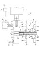
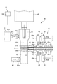
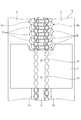
- FIG. 1 is a schematic side view illustrating a first embodiment of a reinforcing film bonding apparatus according to the present invention. It is the partially cutaway side view which looked at the reinforcement film bonding apparatus shown in FIG. 1 from the downstream. It is an enlarged view of the periphery of the fastener chain of FIG. It is an enlarged view of the cutting part of the film supply apparatus shown in FIG. It is a side view corresponding to Drawing 2 explaining the state where the upper and lower reinforcement films are conveyed by the film supply device to the upper and lower surfaces of the fastener chain between the ultrasonic horn and the anvil, respectively.
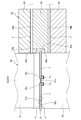
- FIG. 3 is a side view corresponding to FIG.
- the upper side is the upper side with respect to the paper surface of FIG. 1
- the lower side is the lower side with respect to the paper surface of FIG. 1
- the left side is with respect to the paper surface of FIG.
- the near side and the right side are the back side with respect to the paper surface of FIG. 1
- the upstream side is the left side with respect to the paper surface of FIG. 1
- the downstream side is the right side with respect to the paper surface of FIG.
- the left-right direction of a reinforcement film bonding apparatus is also called the width direction.
- the reinforcing film bonding apparatus 10 includes a chain conveying device 20 that intermittently conveys the fastener chain C, and chain guide plates 31 and 32 that guide the conveyed fastener chain C.
- the upper and lower surfaces of the fastener chain C and the upper and lower surfaces of the fastener chain C are cut into the upper and lower reinforcing films F and the film supply device 40 for supplying the synthetic resin reinforcing films F to the upper and lower surfaces.
- a welding device (adhesive device) 50 for welding each, and the cut reinforcing film F is welded to the fastener tape T in the space S portion of the fastener chain C.
- the fastener chain C includes a pair of left and right fastener tapes T and a pair of left and right fastener elements attached along the core string Ta at the tape side edge portions of the pair of left and right fastener tapes T facing each other.
- the fastener element row EL has a plurality of fastener elements E.
- the fastener element row EL is a coiled fastener element row.
- the fastener chain C is formed with a space S at a predetermined interval in which the fastener element E is not attached or the fastener element E is removed and the side edges of the tape face each other.
- the chain transport device 20 includes a feed roll device 21 that transports the fastener chain C, and a space detection device 22 that detects a space S of the fastener chain C.
- the feed roll device 21 includes a feed roller 21a disposed below the fastener chain C and a press roller 21b disposed above the fastener chain C. Moreover, in the feed roll apparatus 21, the feed length of the fastener chain C is measured in the feed roller 21a.
- the space detection device 22 includes a swing lever 22a having a sensing roller 22b at the tip. In the space detection device 22, when the sensing roller 22b enters the space S of the fastener chain C to be conveyed, the swing lever 22a swings downward and the space S is detected.
- the space S of the fastener chain C conveyed by the feed roll device 21 is detected by the space detecting device 22, the space S of the fastener chain C is a predetermined position of the welding device 50.
- the feed chain device 21 stops the conveyance of the fastener chain C so as to stop. And the fastener chain C is intermittently conveyed by repeating the said operation
- the film supply device 40 is inserted through a film transport unit 41 that transports the upper and lower reinforcing films F and an upper and lower reinforcing film F that is transported from the film transport unit 41. And a cutting portion 45 that cuts the upper and lower reinforcing films F between the ultrasonic horn 51 and the anvil 52.
- the film supply device 40 is provided so as to extend from the welding device 50 to the right side in the width direction.
- the welding device 50 includes an ultrasonic horn 51 provided on the upper surface side of the fastener chain C so as to be movable up and down, and an anvil 52 provided on the lower surface side of the fastener chain C so as to be movable up and down. .
- the ultrasonic horn 51 is formed at the lower end surface, which is a pressing surface 51 a that presses the reinforcing film F against the upper surface of the fastener chain C, and the left and right edges of the pressing surface 51 a. And a cutting blade 51b.
- the right cutting blade 51b is used for cutting
- the left cutting blade 51b is used with its right and left reversed when the right cutting blade 51b is worn.
- a convex portion 51c that enters between the left and right fastener tapes T of the fastener chain C when the ultrasonic horn 51 is moved downward (when the film is welded, see FIG. 7) is pressed on the pressing surface 51a of the ultrasonic horn 51. It is formed along the conveyance direction of the fastener chain C at the center in the width direction of the surface 51a.
- the anvil 52 is formed at the upper end surface of the pressing surface 52 a that presses the reinforcing film F against the lower surface of the fastener chain C, and the left and right edges of the pressing surface 52 a, and cuts the reinforcing film F.
- Cutting blade 52b is used for cutting, and the left cutting blade 52b is used with its right and left reversed when the right cutting blade 52b is worn.
- the pressing surface 52a of the anvil 52 has a pair of recesses 52c for receiving the left and right core strings Ta of the fastener chain C when the anvil 52 is moved upward (when the film is welded, see FIG. 7). It is formed along the conveyance direction of the fastener chain C at symmetrical positions with the width direction center therebetween.
- the reinforcing film bonding apparatus 10 includes a first preloading device 61 and a second preloading device 62 that urge the ultrasonic horn 51 and the anvil 52 of the welding device 50 toward the film supply device 40, respectively. Prepare. For this reason, the cutting blades 51b and 52b of the ultrasonic horn 51 and the anvil 52 are pressed against the distal end surface 45a of the cutting portion 45 of the film supply device 40 by the urging force of the first preloading device 61 and the second preloading device 62. The reinforcing film F can be cut efficiently.
- the first preload device 61 includes a cylinder 61a and a pressing roller 61c attached to the tip of the rod 61b of the cylinder 61a.
- the second preloading device 62 includes a pressing roller 62a that is constantly urged toward the anvil 52 side by a spring (not shown). Then, the first preload device 61 is driven so that the rod 61 b is contracted after the film is cut by the ultrasonic horn 51 and the pressing roller 61 c is separated from the ultrasonic horn 51. For this reason, since the ultrasonic horn 51 and the pressing roller 61c become non-contact, the vibration of the ultrasonic horn 51 performed after film cutting is not inhibited.
- the ultrasonic horn 51 is provided with an adsorption device 53 for adsorbing the cut reinforcing film F as shown in FIG. 1 and FIG.
- the suction device 53 communicates with two vertical holes 53 a that open in the pressing surface 51 a of the ultrasonic horn 51 and the upper ends of the two vertical holes 53 a, and one horizontal hole 53 b that opens in the side surface of the ultrasonic horn 51.
- a suction device 54 connected to the lateral hole 53b. Examples of the suction device 54 include a vacuum pump and a suction pump.
- the two vertical holes 53a of the suction device 53 are formed in parallel along the conveying direction of the fastener chain C at the center in the width direction of the ultrasonic horn 51, as shown in FIGS. Accordingly, the openings of the two vertical holes 53 a are arranged on the convex portion 51 c of the pressing surface 51 a of the ultrasonic horn 51. For this reason, the adsorption trace Ft by adsorption
- the suction device 54 sucks air from the two vertical holes 53a when the film is cut, so that the cut upper reinforcing film F is applied to the pressing surface 51a of the ultrasonic horn 51. Adsorbed. For this reason, the position shift of the reinforcing film F at the time of cutting the reinforcing film F with the ultrasonic horn 51 is prevented. Further, after the film is welded, the dust from the reinforcing film F that has melted and entered the two vertical holes 53a is discharged to the outside by spraying air from the two vertical holes 53a. Thereby, clogging of the two vertical holes 53a can be prevented.
- the film transport unit 41 of the film supply device 40 includes a film guide 42 that guides the upper and lower reinforcing films F, and an upper and lower first pressing device that transports the upper and lower reinforcing films F to the welding device 50 side. 43 and upper and lower second pressing devices 44 that fix the positions of the conveyed upper and lower reinforcing films F.
- the film guide 42 includes a film guide plate 42a and upper and lower film guide covers 42b that form a conveyance path for the reinforcing film F between the upper and lower surfaces of the film guide plate 42a.
- the reinforcing film F has a tape shape and is continuously passed through the film guide 42 and the film conveyance path of the cutting portion 45.
- the first pressing device 43 includes a cylinder 43a and a pressing pad 43c attached to the tip of the rod 43b of the cylinder 43a, and is provided to be slidable along the longitudinal direction of the film guide 42. And according to this 1st press apparatus 43, while extending the rod 43b and pressing the reinforcement film F to the film guide plate 42a with the press pad 43c, the 1st press apparatus 43 is slid and moved to the welding apparatus 50 side. The reinforcing film F having a certain length is conveyed to the welding device 50 side (see FIG. 5). Further, the upper and lower first pressing devices 43 are provided to perform the same drive.
- the second pressing device 44 includes a cylinder 44a and a pressing pad 44c attached to the tip of the rod 44b of the cylinder 44a. According to the second pressing device 44, the position of the reinforcing film F is fixed by extending the rod 44b and pressing the reinforcing film F against the film guide plate 42a with the pressing pad 44c (see FIG. 6).
- the upper and lower second pressing devices 44 are provided to perform the same drive.
- the cutting portion 45 of the film supply apparatus 40 is fitted into a cutting portion main body 46 that is a block member having a substantially H shape in side view and upper and lower concave portions 47 of the cutting portion main body 46.
- the upper and lower block bodies 49 that form the conveying path of the reinforcing film F between the cutting blades 48a and 48b, which are the bottom surfaces of the upper and lower concave portions 47 of the cutting portion main body 46, are provided.
- the distal end surface 45 a of the above-described cutting portion 45 is configured by the distal end surfaces of the cutting portion main body 46 and the block body 49.
- the upper cutting blade 48a of the cutting part main body 46 is formed in a V shape in a side view
- the lower cutting blade 48b is formed in an inverted V shape in a side view.
- the V-shaped apexes of the upper and lower cutting blades 48 a and 48 b are arranged at the center in the width direction of the reinforcing film F.
- the shear angle ⁇ of the upper and lower cutting blades 48a and 48b is set to 3 ° to 10 °, preferably 6 °. Note that the reinforcing film F is actually cut at the edges of the upper and lower cutting blades 48a and 48b.
- a concave groove 46a extending along the conveying direction of the fastener chain C is formed between the upper and lower cutting blades 48a, 48b on the tip surface of the cutting portion main body 46.
- the concave groove 46a is for the cutting blade 51b of the ultrasonic horn 51 after film cutting to enter. For this reason, since the cutting blade 51b of the ultrasonic horn 51 and the cutting portion 45 are not in contact with each other, the vibration of the ultrasonic horn 51 performed after film cutting is not hindered. Further, the concave groove 46a allows the outer edge of the fastener chain C to pass therethrough.
- the fastener chain C is transferred downstream by the feed roll device 21, and the space S of the fastener chain C is detected by the space detection device 22, so that the space S of the fastener chain C is welded.
- the device 50 is stopped at a predetermined position between the ultrasonic horn 51 and the anvil 52. At this time, the suction device 54 is not operated, and air is not sucked from the vertical hole 53a.
- the upper and lower reinforcing films F are respectively conveyed to the upper and lower surfaces of the fastener chain C between the ultrasonic horn 51 and the anvil 52 by the upper and lower first pressing devices 43 of the film supply device 40.
- the position of the upper and lower reinforcing films F is fixed by the upper and lower second pressing devices 44 of the film supply device 40 after the film is conveyed.
- the urging of the ultrasonic horn 51 and the anvil 52 by the first and second preloading devices 61 and 62 is started.
- the pressing roller 61 c of the first preload device 61 is separated from the ultrasonic horn 51 during film welding. Then, the ultrasonic horn 51 and the anvil 52 are returned to their original positions. Thus, by repeating the above operation, the reinforcing film F cut into the spaces S provided at predetermined intervals of the fastener chain C is continuously welded.
- the convex portion 51c of the ultrasonic horn 51 enters between the left and right fastener tapes T of the fastener chain C, and the left and right core cords Ta of the fastener chain C are accommodated in the pair of concave portions 52c of the anvil 52.
- the reinforcing film F is welded to the inner side surfaces of the left and right fastener tapes T by the side wall surfaces of the convex portions 51c, and the reinforcing film F is welded to the inner side surfaces of the left and right core cords Ta by the inner wall surfaces of the concave portions 52c.
- the inner side surfaces of the left and right fastener tapes T are the right side surface of the left side fastener tape T and the left side surface of the right side fastener tape T.
- the inner side surfaces of the left and right core cords Ta are the right side surface of the left side core cord Ta and the left side surface of the right side core cord Ta.
- the pressing surface 51a of the ultrasonic horn 51 is placed between the left and right fastener tapes T of the fastener chain C when the ultrasonic horn 51 is moved downward.
- a convex portion 51c is formed, and a pair of concave portions 52c are formed on the pressing surface 52a of the anvil 52 to accommodate the left and right core cords Ta of the fastener chain C when the anvil 52 is moved upward.
- the reinforcing film F is welded to the inner side surfaces of the left and right fastener tapes T by the side wall surfaces, and the reinforcing film F is welded to the inner side surfaces of the left and right core cords Ta by the inner wall surface of the recess 52c. Therefore, the reinforcing film F can be bonded to the inner surface of the core string Ta of the fastener chain C.
- the reinforcing film bonding apparatus 10 of the present embodiment in order to cut the reinforcing film F with the ultrasonic horn 51 and the anvil 52 and bond the cut reinforcing film F to the upper and lower surfaces of the fastener chain C, respectively. There is no need to separately provide a device for cutting the reinforcing film F. Thereby, since the number of parts can be reduced, the manufacturing cost can be reduced.
- the ultrasonic horn 51 provided on the upper surface side of the fastener chain C is provided with the suction device 53 that adsorbs the cut reinforcing film F, the ultrasonic horn The upper reinforcing film F cut by 51 is adsorbed to the pressing surface 51 a of the ultrasonic horn 51. For this reason, since position shift of the reinforcement film F at the time of cutting the reinforcement film F with the ultrasonic horn 51 can be prevented, the reinforcement film F can be welded to a predetermined position of the fastener chain C.
- the anvil 52 may be provided with an adsorption device 53 that adsorbs the cut reinforcing film F.
- the suction device 53 of the anvil 52 has the same configuration as the suction device 53 of the ultrasonic horn 51.
- the suction device 53 of the ultrasonic horn 51 and the anvil 52 has the individual suction devices 54, respectively, but one suction device 54 may be shared. However, it is more preferable to provide the suction device 54 individually because the suction force can be set individually.
- the upper reinforcing film F cut by the ultrasonic horn 51 is adsorbed to the pressing surface 51 a of the ultrasonic horn 51, and the lower reinforcing film F cut by the anvil 52 is Therefore, when the reinforcing film F is cut by the ultrasonic horn 51 and the anvil 52, the positional displacement of the reinforcing film F can be prevented.
- the reinforcing film F can be welded.
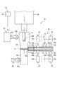
- the reinforcing film bonding apparatus 110 grips the upper and lower reinforcing films F and the film supplying apparatus 140 that supplies the reinforcing films F made of synthetic resin to the upper and lower surfaces of the fastener chain C, respectively.
- An apparatus (bonding apparatus) 170 the reinforcing film bonding apparatus 110 includes the chain conveyance device 20 and the chain guide plates 31 and 32 as in the first embodiment.
- the film supply device 140 is inserted between a film transport unit 141 that transports the upper and lower reinforcing films F, and the upper and lower reinforcing films F transported from the film transport unit 141, and moves vertically between the cutter 161 of the cutting device 160 described later. And a cutting portion 145 for cutting the reinforcing film F. Further, the film supply device 140 is provided so as to extend to the right side in the width direction of the welding device 170.
- the film transport unit 141 includes a film guide 142 that guides the upper and lower reinforcing films F.
- the film guide 142 includes a film guide plate 142a and upper and lower film guide covers 142b that form a conveyance path for the reinforcing film F between the upper and lower surfaces of the film guide plate 142a.
- the reinforcing film F has a tape shape and is continuously passed through the film guide 142 and the film conveyance path of the cutting portion 145.
- the cutting part 145 is provided so as to be slidable in the left-right direction, and is always urged in a direction approaching the fastener chain C by a spring (not shown).
- the cutting device 160 includes a cutter 161 disposed below the cutting unit 145 and a cylinder device 162 that moves the cutter 161 up and down.
- the cutter 161 is attached to the upper end of the rod 162a of the cylinder device 162.
- the welding apparatus 170 includes an ultrasonic horn 171 provided on the upper surface side of the fastener chain C so as to be movable up and down, and an anvil 172 provided on the lower surface side of the fastener chain C so as to be movable up and down.
- the ultrasonic horn 171 has a pressing surface 171a which is the lower end surface thereof and presses the reinforcing film F against the upper surface of the fastener chain C.
- a convex portion 171b similar to the convex portion 51c of the ultrasonic horn 51 of the first embodiment is formed on the pressing surface 171a of the ultrasonic horn 171.
- the anvil 172 has a pressing surface 172a that is the upper end surface thereof and presses the reinforcing film F against the lower surface of the fastener chain C.
- a pair of recesses 172b similar to the pair of recesses 52c of the anvil 52 of the first embodiment are formed on the pressing surface 172a of the anvil 172.
- the upper and lower reinforcing films are gripped by the gripper 150. F is pulled out to the upper and lower surfaces of the fastener chain C, respectively.
- the cutter 161 of the cutting device 160 moves up, the upper and lower reinforcing films F are cut between the cutter 161 and the tip end surface 145a of the cutting portion 145.
- the ultrasonic horn 171 is moved downward and the anvil 172 is moved upward, whereby the cut upper and lower reinforcing films F are welded to the upper and lower surfaces of the fastener chain C, respectively.
- the pressing surface 171a of the ultrasonic horn 171 is moved between the left and right fastener tapes T of the fastener chain C when the ultrasonic horn 171 is moved downward.
- a convex portion 171b is formed, and a pair of concave portions 172b for accommodating the left and right core cords Ta of the fastener chain C are formed on the pressing surface 172a of the anvil 172 when the anvil 172 is moved upward.
- the reinforcing film F is welded to the inner side surfaces of the left and right fastener tapes T by the side wall surfaces, and the reinforcing film F is welded to the inner side surfaces of the left and right core cords Ta by the inner wall surfaces of the recesses 172b. Therefore, the reinforcing film F can be bonded to the inner surface of the core string Ta of the fastener chain C. About another structure and an effect, it is the same as that of the said 1st Embodiment.
- this invention is not limited to what was illustrated by said each embodiment, In the range which does not deviate from the summary of this invention, it can change suitably.
- the welding apparatus of this embodiment is an ultrasonic system, it is not limited to this, A high frequency system and a heater system may be used.
- the ultrasonic horn is provided on the upper surface side of the fastener chain and the anvil is provided on the lower surface side.
- the present invention is not limited thereto, and the anvil is provided on the upper surface side of the fastener chain.
- An ultrasonic horn may be provided.
Landscapes
- Lining Or Joining Of Plastics Or The Like (AREA)
- Making Paper Articles (AREA)
Abstract
La présente invention concerne un dispositif d'adhésion de film de renfort avec lequel un film de renfort peut adhérer jusqu'à une surface côté interne d'un cordon central d'une chaîne de fermeture. La présente invention comprend un dispositif de transport à chaîne (20) qui transporte par intermittence une chaîne de fermeture (C), un dispositif d'alimentation en film (40) qui fournit un film de renfort en résine synthétique (F) aux surfaces supérieure et inférieure de la chaîne de fermeture (C), et un dispositif d'adhésion (50) qui fait adhérer le film de renfort (F) aux surfaces supérieure et inférieure de la chaîne de fermeture (C) et qui est pourvu d'un émetteur d'ultrasons (51) prévu sur un côté de la chaîne de fermeture (C) de manière à être mobile verticalement et d'une enclume (52) prévue sur l'autre côté de la chaîne de fermeture (C) de manière à être mobile verticalement. Une partie faisant saillie (51c), qui pénètre entre une paire de rubans de fermeture (T) dans la chaîne de fermeture (C) lorsque l'émetteur d'ultrasons (51) se déplace, est formée dans une surface de pression (51a) de l'émetteur d'ultrasons (51), et une paire de parties évidées (52c), qui reçoivent une paire de cordons centraux (Ta) de la chaîne de fermeture (C) lorsque l'enclume (52) se déplace, sont formées dans une surface de pression (52a) de l'enclume (52).
Priority Applications (3)
| Application Number | Priority Date | Filing Date | Title |
|---|---|---|---|
| CN201480002950.6A CN104797157B (zh) | 2014-03-24 | 2014-03-24 | 增强膜粘着装置 |
| PCT/JP2014/058085 WO2015145545A1 (fr) | 2014-03-24 | 2014-03-24 | Dispositif d'adhésion de film de renfort |
| TW104109129A TWI587810B (zh) | 2014-03-24 | 2015-03-23 | 增強膜黏著裝置 |
Applications Claiming Priority (1)
| Application Number | Priority Date | Filing Date | Title |
|---|---|---|---|
| PCT/JP2014/058085 WO2015145545A1 (fr) | 2014-03-24 | 2014-03-24 | Dispositif d'adhésion de film de renfort |
Publications (1)
| Publication Number | Publication Date |
|---|---|
| WO2015145545A1 true WO2015145545A1 (fr) | 2015-10-01 |
Family
ID=53561514
Family Applications (1)
| Application Number | Title | Priority Date | Filing Date |
|---|---|---|---|
| PCT/JP2014/058085 Ceased WO2015145545A1 (fr) | 2014-03-24 | 2014-03-24 | Dispositif d'adhésion de film de renfort |
Country Status (3)
| Country | Link |
|---|---|
| CN (1) | CN104797157B (fr) |
| TW (1) | TWI587810B (fr) |
| WO (1) | WO2015145545A1 (fr) |
Families Citing this family (2)
| Publication number | Priority date | Publication date | Assignee | Title |
|---|---|---|---|---|
| WO2017061018A1 (fr) * | 2015-10-08 | 2017-04-13 | Ykk株式会社 | Dispositif d'assemblage d'éléments en forme de film |
| CN109431014A (zh) * | 2018-11-29 | 2019-03-08 | 深圳市联星服装辅料有限公司 | 一种镭射防水拉链的工装夹具及镭射防水拉链的制作方法 |
Citations (7)
| Publication number | Priority date | Publication date | Assignee | Title |
|---|---|---|---|---|
| JPS58188402A (ja) * | 1982-04-28 | 1983-11-02 | ワイケイケイ株式会社 | スライドフアスナ−チエンの開離嵌挿具取付部分に対する補強帯付着方法ならびに装置 |
| JPS58188249A (ja) * | 1982-04-28 | 1983-11-02 | Yoshida Kogyo Kk <Ykk> | テ−プ状物の間欠送り装置 |
| JPS60126104A (ja) * | 1983-12-12 | 1985-07-05 | ワイケイケイ株式会社 | 開離嵌插具付スライドフアスナ−の補強テ−プ貼着方法 |
| JPH02237794A (ja) * | 1989-03-10 | 1990-09-20 | Sumitomo Metal Mining Co Ltd | テープ状材料切断装置 |
| JPH06144689A (ja) * | 1992-11-06 | 1994-05-24 | Yoshida Kogyo Kk <Ykk> | テープカセット及び熱溶着性テープ片の自動貼着装置 |
| CN2317070Y (zh) * | 1998-02-06 | 1999-05-05 | 刘维尧 | 超音波拉链胶膜成型切断机 |
| JP2003189913A (ja) * | 2001-12-28 | 2003-07-08 | Ykk Corp | ファスナーテープに対する補強テープ片の超音波溶着方法及び溶着装置 |
Family Cites Families (3)
| Publication number | Priority date | Publication date | Assignee | Title |
|---|---|---|---|---|
| JP3827273B2 (ja) * | 1999-12-24 | 2006-09-27 | Ykk株式会社 | 超音波接着方法と装置 |
| CN2785411Y (zh) * | 2005-04-08 | 2006-06-07 | 吕永平 | 双面内贴拉链贴布机之切胶机构 |
| CN104302203B (zh) * | 2013-05-02 | 2017-06-30 | Ykk株式会社 | 补强膜粘接装置 |
-
2014
- 2014-03-24 WO PCT/JP2014/058085 patent/WO2015145545A1/fr not_active Ceased
- 2014-03-24 CN CN201480002950.6A patent/CN104797157B/zh active Active
-
2015
- 2015-03-23 TW TW104109129A patent/TWI587810B/zh active
Patent Citations (7)
| Publication number | Priority date | Publication date | Assignee | Title |
|---|---|---|---|---|
| JPS58188402A (ja) * | 1982-04-28 | 1983-11-02 | ワイケイケイ株式会社 | スライドフアスナ−チエンの開離嵌挿具取付部分に対する補強帯付着方法ならびに装置 |
| JPS58188249A (ja) * | 1982-04-28 | 1983-11-02 | Yoshida Kogyo Kk <Ykk> | テ−プ状物の間欠送り装置 |
| JPS60126104A (ja) * | 1983-12-12 | 1985-07-05 | ワイケイケイ株式会社 | 開離嵌插具付スライドフアスナ−の補強テ−プ貼着方法 |
| JPH02237794A (ja) * | 1989-03-10 | 1990-09-20 | Sumitomo Metal Mining Co Ltd | テープ状材料切断装置 |
| JPH06144689A (ja) * | 1992-11-06 | 1994-05-24 | Yoshida Kogyo Kk <Ykk> | テープカセット及び熱溶着性テープ片の自動貼着装置 |
| CN2317070Y (zh) * | 1998-02-06 | 1999-05-05 | 刘维尧 | 超音波拉链胶膜成型切断机 |
| JP2003189913A (ja) * | 2001-12-28 | 2003-07-08 | Ykk Corp | ファスナーテープに対する補強テープ片の超音波溶着方法及び溶着装置 |
Also Published As
| Publication number | Publication date |
|---|---|
| CN104797157A (zh) | 2015-07-22 |
| CN104797157B (zh) | 2017-06-30 |
| TW201536207A (zh) | 2015-10-01 |
| TWI587810B (zh) | 2017-06-21 |
Similar Documents
| Publication | Publication Date | Title |
|---|---|---|
| CN103068684B (zh) | 片材剥离装置及剥离方法以及片材粘贴装置及粘贴方法 | |
| US8544519B2 (en) | Tack labeler | |
| CN101223093B (zh) | 用于拼接标签带的装置和方法 | |
| JP2010523350A (ja) | 予備含浸されたストリップから切断されたトリミング屑を分離および排出するための装置 | |
| KR101605625B1 (ko) | 디스플레이장치용 접착시트 제조장치 | |
| TWI546029B (zh) | 增強膜黏著裝置及具有可分離式嵌插件的拉鏈 | |
| TWI538635B (zh) | 補強膜黏著裝置 | |
| WO2015145545A1 (fr) | Dispositif d'adhésion de film de renfort | |
| KR100795910B1 (ko) | 접착제가 내측에 도포되어 있는 카드 컷팅장치 | |
| CN105101832B (zh) | 止部安装装置 | |
| CN204763765U (zh) | 增强膜粘着装置 | |
| JP2003252495A (ja) | 紙接続装置及び紙接続方法 | |
| JP5011251B2 (ja) | 貼り付け基板用製造装置及びその不良フイルム廃棄方法 | |
| CN108521770A (zh) | 用于胶合、处理和储存模切材料的方法 | |
| JP2015107850A (ja) | 保護紙剥離分離処理装置 | |
| CN112794152B (zh) | 拨胶机构以及贴胶装置 | |
| KR20140004256U (ko) | 일자형 파우치 겸용 형상 파우치 커팅장치 | |
| KR102067943B1 (ko) | 종이디스크 제조장치 | |
| JP2009096629A (ja) | コンベア | |
| JP5890143B2 (ja) | 包装袋の製造装置 | |
| KR101687817B1 (ko) | 백 테이프 및 그의 제조 방법 | |
| CN104487214A (zh) | 手、机器人以及加工系统 | |
| TW201709786A (zh) | 適用於軟性印刷電路板的接料裝置 | |
| TWM514178U (zh) | 適用於軟性印刷電路板的接料裝置 | |
| JP2004001813A (ja) | ラベル分離装置 |
Legal Events
| Date | Code | Title | Description |
|---|---|---|---|
| 121 | Ep: the epo has been informed by wipo that ep was designated in this application |
Ref document number: 14887096 Country of ref document: EP Kind code of ref document: A1 |
|
| NENP | Non-entry into the national phase |
Ref country code: DE |
|
| 122 | Ep: pct application non-entry in european phase |
Ref document number: 14887096 Country of ref document: EP Kind code of ref document: A1 |
|
| NENP | Non-entry into the national phase |
Ref country code: JP |