WO2015146690A1 - 複合材構造体、これを備えた航空機翼および航空機胴体、並びに複合材構造体の製造方法 - Google Patents
複合材構造体、これを備えた航空機翼および航空機胴体、並びに複合材構造体の製造方法 Download PDFInfo
- Publication number
- WO2015146690A1 WO2015146690A1 PCT/JP2015/057786 JP2015057786W WO2015146690A1 WO 2015146690 A1 WO2015146690 A1 WO 2015146690A1 JP 2015057786 W JP2015057786 W JP 2015057786W WO 2015146690 A1 WO2015146690 A1 WO 2015146690A1
- Authority
- WO
- WIPO (PCT)
- Prior art keywords
- composite material
- area
- hole
- continuous fibers
- region
- Prior art date
- Legal status (The legal status is an assumption and is not a legal conclusion. Google has not performed a legal analysis and makes no representation as to the accuracy of the status listed.)
- Ceased
Links
Images

Classifications
-
- B—PERFORMING OPERATIONS; TRANSPORTING
- B32—LAYERED PRODUCTS
- B32B—LAYERED PRODUCTS, i.e. PRODUCTS BUILT-UP OF STRATA OF FLAT OR NON-FLAT, e.g. CELLULAR OR HONEYCOMB, FORM
- B32B5/00—Layered products characterised by the non- homogeneity or physical structure, i.e. comprising a fibrous, filamentary, particulate or foam layer; Layered products characterised by having a layer differing constitutionally or physically in different parts
- B32B5/02—Layered products characterised by the non- homogeneity or physical structure, i.e. comprising a fibrous, filamentary, particulate or foam layer; Layered products characterised by having a layer differing constitutionally or physically in different parts characterised by structural features of a fibrous or filamentary layer
- B32B5/12—Layered products characterised by the non- homogeneity or physical structure, i.e. comprising a fibrous, filamentary, particulate or foam layer; Layered products characterised by having a layer differing constitutionally or physically in different parts characterised by structural features of a fibrous or filamentary layer characterised by the relative arrangement of fibres or filaments of different layers, e.g. the fibres or filaments being parallel or perpendicular to each other
-
- B—PERFORMING OPERATIONS; TRANSPORTING
- B29—WORKING OF PLASTICS; WORKING OF SUBSTANCES IN A PLASTIC STATE IN GENERAL
- B29C—SHAPING OR JOINING OF PLASTICS; SHAPING OF MATERIAL IN A PLASTIC STATE, NOT OTHERWISE PROVIDED FOR; AFTER-TREATMENT OF THE SHAPED PRODUCTS, e.g. REPAIRING
- B29C70/00—Shaping composites, i.e. plastics material comprising reinforcements, fillers or preformed parts, e.g. inserts
- B29C70/04—Shaping composites, i.e. plastics material comprising reinforcements, fillers or preformed parts, e.g. inserts comprising reinforcements only, e.g. self-reinforcing plastics
- B29C70/06—Fibrous reinforcements only
-
- B—PERFORMING OPERATIONS; TRANSPORTING
- B64—AIRCRAFT; AVIATION; COSMONAUTICS
- B64C—AEROPLANES; HELICOPTERS
- B64C3/00—Wings
- B64C3/26—Construction, shape, or attachment of separate skins, e.g. panels
-
- B—PERFORMING OPERATIONS; TRANSPORTING
- B29—WORKING OF PLASTICS; WORKING OF SUBSTANCES IN A PLASTIC STATE IN GENERAL
- B29C—SHAPING OR JOINING OF PLASTICS; SHAPING OF MATERIAL IN A PLASTIC STATE, NOT OTHERWISE PROVIDED FOR; AFTER-TREATMENT OF THE SHAPED PRODUCTS, e.g. REPAIRING
- B29C53/00—Shaping by bending, folding, twisting, straightening or flattening; Apparatus therefor
- B29C53/02—Bending or folding
-
- B—PERFORMING OPERATIONS; TRANSPORTING
- B29—WORKING OF PLASTICS; WORKING OF SUBSTANCES IN A PLASTIC STATE IN GENERAL
- B29C—SHAPING OR JOINING OF PLASTICS; SHAPING OF MATERIAL IN A PLASTIC STATE, NOT OTHERWISE PROVIDED FOR; AFTER-TREATMENT OF THE SHAPED PRODUCTS, e.g. REPAIRING
- B29C70/00—Shaping composites, i.e. plastics material comprising reinforcements, fillers or preformed parts, e.g. inserts
- B29C70/04—Shaping composites, i.e. plastics material comprising reinforcements, fillers or preformed parts, e.g. inserts comprising reinforcements only, e.g. self-reinforcing plastics
- B29C70/06—Fibrous reinforcements only
- B29C70/10—Fibrous reinforcements only characterised by the structure of fibrous reinforcements, e.g. hollow fibres
- B29C70/16—Fibrous reinforcements only characterised by the structure of fibrous reinforcements, e.g. hollow fibres using fibres of substantial or continuous length
- B29C70/20—Fibrous reinforcements only characterised by the structure of fibrous reinforcements, e.g. hollow fibres using fibres of substantial or continuous length oriented in a single direction, e.g. roofing or other parallel fibres
- B29C70/202—Fibrous reinforcements only characterised by the structure of fibrous reinforcements, e.g. hollow fibres using fibres of substantial or continuous length oriented in a single direction, e.g. roofing or other parallel fibres arranged in parallel planes or structures of fibres crossing at substantial angles, e.g. cross-moulding compound [XMC]
-
- B—PERFORMING OPERATIONS; TRANSPORTING
- B29—WORKING OF PLASTICS; WORKING OF SUBSTANCES IN A PLASTIC STATE IN GENERAL
- B29C—SHAPING OR JOINING OF PLASTICS; SHAPING OF MATERIAL IN A PLASTIC STATE, NOT OTHERWISE PROVIDED FOR; AFTER-TREATMENT OF THE SHAPED PRODUCTS, e.g. REPAIRING
- B29C70/00—Shaping composites, i.e. plastics material comprising reinforcements, fillers or preformed parts, e.g. inserts
- B29C70/04—Shaping composites, i.e. plastics material comprising reinforcements, fillers or preformed parts, e.g. inserts comprising reinforcements only, e.g. self-reinforcing plastics
- B29C70/06—Fibrous reinforcements only
- B29C70/10—Fibrous reinforcements only characterised by the structure of fibrous reinforcements, e.g. hollow fibres
- B29C70/16—Fibrous reinforcements only characterised by the structure of fibrous reinforcements, e.g. hollow fibres using fibres of substantial or continuous length
- B29C70/22—Fibrous reinforcements only characterised by the structure of fibrous reinforcements, e.g. hollow fibres using fibres of substantial or continuous length oriented in at least two directions forming a two-dimensional [2D] structure
- B29C70/228—Fibrous reinforcements only characterised by the structure of fibrous reinforcements, e.g. hollow fibres using fibres of substantial or continuous length oriented in at least two directions forming a two-dimensional [2D] structure the structure being stacked in parallel layers with fibres of adjacent layers crossing at substantial angles
-
- B—PERFORMING OPERATIONS; TRANSPORTING
- B29—WORKING OF PLASTICS; WORKING OF SUBSTANCES IN A PLASTIC STATE IN GENERAL
- B29C—SHAPING OR JOINING OF PLASTICS; SHAPING OF MATERIAL IN A PLASTIC STATE, NOT OTHERWISE PROVIDED FOR; AFTER-TREATMENT OF THE SHAPED PRODUCTS, e.g. REPAIRING
- B29C70/00—Shaping composites, i.e. plastics material comprising reinforcements, fillers or preformed parts, e.g. inserts
- B29C70/04—Shaping composites, i.e. plastics material comprising reinforcements, fillers or preformed parts, e.g. inserts comprising reinforcements only, e.g. self-reinforcing plastics
- B29C70/28—Shaping operations therefor
- B29C70/30—Shaping by lay-up, i.e. applying fibres, tape or broadsheet on a mould, former or core; Shaping by spray-up, i.e. spraying of fibres on a mould, former or core
-
- B—PERFORMING OPERATIONS; TRANSPORTING
- B32—LAYERED PRODUCTS
- B32B—LAYERED PRODUCTS, i.e. PRODUCTS BUILT-UP OF STRATA OF FLAT OR NON-FLAT, e.g. CELLULAR OR HONEYCOMB, FORM
- B32B3/00—Layered products comprising a layer with external or internal discontinuities or unevennesses, or a layer of non-planar shape; Layered products comprising a layer having particular features of form
- B32B3/26—Layered products comprising a layer with external or internal discontinuities or unevennesses, or a layer of non-planar shape; Layered products comprising a layer having particular features of form characterised by a particular shape of the outline of the cross-section of a continuous layer; characterised by a layer with cavities or internal voids ; characterised by an apertured layer
- B32B3/266—Layered products comprising a layer with external or internal discontinuities or unevennesses, or a layer of non-planar shape; Layered products comprising a layer having particular features of form characterised by a particular shape of the outline of the cross-section of a continuous layer; characterised by a layer with cavities or internal voids ; characterised by an apertured layer characterised by an apertured layer, the apertures going through the whole thickness of the layer, e.g. expanded metal, perforated layer, slit layer regular cells B32B3/12
-
- B—PERFORMING OPERATIONS; TRANSPORTING
- B32—LAYERED PRODUCTS
- B32B—LAYERED PRODUCTS, i.e. PRODUCTS BUILT-UP OF STRATA OF FLAT OR NON-FLAT, e.g. CELLULAR OR HONEYCOMB, FORM
- B32B5/00—Layered products characterised by the non- homogeneity or physical structure, i.e. comprising a fibrous, filamentary, particulate or foam layer; Layered products characterised by having a layer differing constitutionally or physically in different parts
- B32B5/02—Layered products characterised by the non- homogeneity or physical structure, i.e. comprising a fibrous, filamentary, particulate or foam layer; Layered products characterised by having a layer differing constitutionally or physically in different parts characterised by structural features of a fibrous or filamentary layer
- B32B5/06—Layered products characterised by the non- homogeneity or physical structure, i.e. comprising a fibrous, filamentary, particulate or foam layer; Layered products characterised by having a layer differing constitutionally or physically in different parts characterised by structural features of a fibrous or filamentary layer characterised by a fibrous or filamentary layer mechanically connected, e.g. by needling to another layer, e.g. of fibres, of paper
-
- B—PERFORMING OPERATIONS; TRANSPORTING
- B32—LAYERED PRODUCTS
- B32B—LAYERED PRODUCTS, i.e. PRODUCTS BUILT-UP OF STRATA OF FLAT OR NON-FLAT, e.g. CELLULAR OR HONEYCOMB, FORM
- B32B5/00—Layered products characterised by the non- homogeneity or physical structure, i.e. comprising a fibrous, filamentary, particulate or foam layer; Layered products characterised by having a layer differing constitutionally or physically in different parts
- B32B5/14—Layered products characterised by the non- homogeneity or physical structure, i.e. comprising a fibrous, filamentary, particulate or foam layer; Layered products characterised by having a layer differing constitutionally or physically in different parts characterised by a layer differing constitutionally or physically in different parts, e.g. denser near its faces
- B32B5/142—Variation across the area of the layer
-
- B—PERFORMING OPERATIONS; TRANSPORTING
- B32—LAYERED PRODUCTS
- B32B—LAYERED PRODUCTS, i.e. PRODUCTS BUILT-UP OF STRATA OF FLAT OR NON-FLAT, e.g. CELLULAR OR HONEYCOMB, FORM
- B32B7/00—Layered products characterised by the relation between layers; Layered products characterised by the relative orientation of features between layers, or by the relative values of a measurable parameter between layers, i.e. products comprising layers having different physical, chemical or physicochemical properties; Layered products characterised by the interconnection of layers
- B32B7/03—Layered products characterised by the relation between layers; Layered products characterised by the relative orientation of features between layers, or by the relative values of a measurable parameter between layers, i.e. products comprising layers having different physical, chemical or physicochemical properties; Layered products characterised by the interconnection of layers with respect to the orientation of features
-
- B—PERFORMING OPERATIONS; TRANSPORTING
- B64—AIRCRAFT; AVIATION; COSMONAUTICS
- B64C—AEROPLANES; HELICOPTERS
- B64C1/00—Fuselages; Constructional features common to fuselages, wings, stabilising surfaces or the like
- B64C1/06—Frames; Stringers; Longerons ; Fuselage sections
- B64C1/068—Fuselage sections
-
- B—PERFORMING OPERATIONS; TRANSPORTING
- B64—AIRCRAFT; AVIATION; COSMONAUTICS
- B64C—AEROPLANES; HELICOPTERS
- B64C1/00—Fuselages; Constructional features common to fuselages, wings, stabilising surfaces or the like
- B64C1/06—Frames; Stringers; Longerons ; Fuselage sections
- B64C1/12—Construction or attachment of skin panels
-
- B—PERFORMING OPERATIONS; TRANSPORTING
- B64—AIRCRAFT; AVIATION; COSMONAUTICS
- B64C—AEROPLANES; HELICOPTERS
- B64C1/00—Fuselages; Constructional features common to fuselages, wings, stabilising surfaces or the like
- B64C1/14—Windows; Doors; Hatch covers or access panels; Surrounding frame structures; Canopies; Windscreens accessories therefor, e.g. pressure sensors, water deflectors, hinges, seals, handles, latches, windscreen wipers
- B64C1/1476—Canopies; Windscreens or similar transparent elements
- B64C1/1492—Structure and mounting of the transparent elements in the window or windscreen
-
- B—PERFORMING OPERATIONS; TRANSPORTING
- B64—AIRCRAFT; AVIATION; COSMONAUTICS
- B64C—AEROPLANES; HELICOPTERS
- B64C3/00—Wings
- B64C3/18—Spars; Ribs; Stringers
-
- B—PERFORMING OPERATIONS; TRANSPORTING
- B64—AIRCRAFT; AVIATION; COSMONAUTICS
- B64C—AEROPLANES; HELICOPTERS
- B64C3/00—Wings
- B64C3/20—Integral or sandwich constructions
-
- B—PERFORMING OPERATIONS; TRANSPORTING
- B64—AIRCRAFT; AVIATION; COSMONAUTICS
- B64C—AEROPLANES; HELICOPTERS
- B64C3/00—Wings
- B64C3/34—Tanks constructed integrally with wings, e.g. for fuel or water
-
- B—PERFORMING OPERATIONS; TRANSPORTING
- B29—WORKING OF PLASTICS; WORKING OF SUBSTANCES IN A PLASTIC STATE IN GENERAL
- B29K—INDEXING SCHEME ASSOCIATED WITH SUBCLASSES B29B, B29C OR B29D, RELATING TO MOULDING MATERIALS OR TO MATERIALS FOR MOULDS, REINFORCEMENTS, FILLERS OR PREFORMED PARTS, e.g. INSERTS
- B29K2105/00—Condition, form or state of moulded material or of the material to be shaped
- B29K2105/06—Condition, form or state of moulded material or of the material to be shaped containing reinforcements, fillers or inserts
- B29K2105/08—Condition, form or state of moulded material or of the material to be shaped containing reinforcements, fillers or inserts of continuous length, e.g. cords, rovings, mats, fabrics, strands or yarns
- B29K2105/10—Cords, strands or rovings, e.g. oriented cords, strands or rovings
- B29K2105/101—Oriented
- B29K2105/105—Oriented uni directionally
-
- B—PERFORMING OPERATIONS; TRANSPORTING
- B29—WORKING OF PLASTICS; WORKING OF SUBSTANCES IN A PLASTIC STATE IN GENERAL
- B29K—INDEXING SCHEME ASSOCIATED WITH SUBCLASSES B29B, B29C OR B29D, RELATING TO MOULDING MATERIALS OR TO MATERIALS FOR MOULDS, REINFORCEMENTS, FILLERS OR PREFORMED PARTS, e.g. INSERTS
- B29K2105/00—Condition, form or state of moulded material or of the material to be shaped
- B29K2105/06—Condition, form or state of moulded material or of the material to be shaped containing reinforcements, fillers or inserts
- B29K2105/08—Condition, form or state of moulded material or of the material to be shaped containing reinforcements, fillers or inserts of continuous length, e.g. cords, rovings, mats, fabrics, strands or yarns
- B29K2105/10—Cords, strands or rovings, e.g. oriented cords, strands or rovings
- B29K2105/101—Oriented
- B29K2105/108—Oriented arranged in parallel planes and crossing at substantial angles
-
- B—PERFORMING OPERATIONS; TRANSPORTING
- B29—WORKING OF PLASTICS; WORKING OF SUBSTANCES IN A PLASTIC STATE IN GENERAL
- B29K—INDEXING SCHEME ASSOCIATED WITH SUBCLASSES B29B, B29C OR B29D, RELATING TO MOULDING MATERIALS OR TO MATERIALS FOR MOULDS, REINFORCEMENTS, FILLERS OR PREFORMED PARTS, e.g. INSERTS
- B29K2307/00—Use of elements other than metals as reinforcement
- B29K2307/04—Carbon
-
- B—PERFORMING OPERATIONS; TRANSPORTING
- B29—WORKING OF PLASTICS; WORKING OF SUBSTANCES IN A PLASTIC STATE IN GENERAL
- B29L—INDEXING SCHEME ASSOCIATED WITH SUBCLASS B29C, RELATING TO PARTICULAR ARTICLES
- B29L2031/00—Other particular articles
- B29L2031/30—Vehicles, e.g. ships or aircraft, or body parts thereof
- B29L2031/3076—Aircrafts
- B29L2031/3082—Fuselages
-
- B—PERFORMING OPERATIONS; TRANSPORTING
- B29—WORKING OF PLASTICS; WORKING OF SUBSTANCES IN A PLASTIC STATE IN GENERAL
- B29L—INDEXING SCHEME ASSOCIATED WITH SUBCLASS B29C, RELATING TO PARTICULAR ARTICLES
- B29L2031/00—Other particular articles
- B29L2031/30—Vehicles, e.g. ships or aircraft, or body parts thereof
- B29L2031/3076—Aircrafts
- B29L2031/3085—Wings
-
- B—PERFORMING OPERATIONS; TRANSPORTING
- B29—WORKING OF PLASTICS; WORKING OF SUBSTANCES IN A PLASTIC STATE IN GENERAL
- B29L—INDEXING SCHEME ASSOCIATED WITH SUBCLASS B29C, RELATING TO PARTICULAR ARTICLES
- B29L2031/00—Other particular articles
- B29L2031/737—Articles provided with holes, e.g. grids, sieves
-
- B—PERFORMING OPERATIONS; TRANSPORTING
- B32—LAYERED PRODUCTS
- B32B—LAYERED PRODUCTS, i.e. PRODUCTS BUILT-UP OF STRATA OF FLAT OR NON-FLAT, e.g. CELLULAR OR HONEYCOMB, FORM
- B32B2250/00—Layers arrangement
- B32B2250/20—All layers being fibrous or filamentary
-
- B—PERFORMING OPERATIONS; TRANSPORTING
- B32—LAYERED PRODUCTS
- B32B—LAYERED PRODUCTS, i.e. PRODUCTS BUILT-UP OF STRATA OF FLAT OR NON-FLAT, e.g. CELLULAR OR HONEYCOMB, FORM
- B32B2260/00—Layered product comprising an impregnated, embedded, or bonded layer wherein the layer comprises an impregnation, embedding, or binder material
- B32B2260/02—Composition of the impregnated, bonded or embedded layer
- B32B2260/021—Fibrous or filamentary layer
- B32B2260/023—Two or more layers
-
- B—PERFORMING OPERATIONS; TRANSPORTING
- B32—LAYERED PRODUCTS
- B32B—LAYERED PRODUCTS, i.e. PRODUCTS BUILT-UP OF STRATA OF FLAT OR NON-FLAT, e.g. CELLULAR OR HONEYCOMB, FORM
- B32B2260/00—Layered product comprising an impregnated, embedded, or bonded layer wherein the layer comprises an impregnation, embedding, or binder material
- B32B2260/04—Impregnation, embedding, or binder material
- B32B2260/046—Synthetic resin
-
- B—PERFORMING OPERATIONS; TRANSPORTING
- B32—LAYERED PRODUCTS
- B32B—LAYERED PRODUCTS, i.e. PRODUCTS BUILT-UP OF STRATA OF FLAT OR NON-FLAT, e.g. CELLULAR OR HONEYCOMB, FORM
- B32B2305/00—Condition, form or state of the layers or laminate
- B32B2305/07—Parts immersed or impregnated in a matrix
-
- B—PERFORMING OPERATIONS; TRANSPORTING
- B32—LAYERED PRODUCTS
- B32B—LAYERED PRODUCTS, i.e. PRODUCTS BUILT-UP OF STRATA OF FLAT OR NON-FLAT, e.g. CELLULAR OR HONEYCOMB, FORM
- B32B2305/00—Condition, form or state of the layers or laminate
- B32B2305/10—Fibres of continuous length
-
- B—PERFORMING OPERATIONS; TRANSPORTING
- B32—LAYERED PRODUCTS
- B32B—LAYERED PRODUCTS, i.e. PRODUCTS BUILT-UP OF STRATA OF FLAT OR NON-FLAT, e.g. CELLULAR OR HONEYCOMB, FORM
- B32B2305/00—Condition, form or state of the layers or laminate
- B32B2305/10—Fibres of continuous length
- B32B2305/20—Fibres of continuous length in the form of a non-woven mat
-
- B—PERFORMING OPERATIONS; TRANSPORTING
- B32—LAYERED PRODUCTS
- B32B—LAYERED PRODUCTS, i.e. PRODUCTS BUILT-UP OF STRATA OF FLAT OR NON-FLAT, e.g. CELLULAR OR HONEYCOMB, FORM
- B32B2307/00—Properties of the layers or laminate
- B32B2307/50—Properties of the layers or laminate having particular mechanical properties
- B32B2307/54—Yield strength; Tensile strength
-
- B—PERFORMING OPERATIONS; TRANSPORTING
- B32—LAYERED PRODUCTS
- B32B—LAYERED PRODUCTS, i.e. PRODUCTS BUILT-UP OF STRATA OF FLAT OR NON-FLAT, e.g. CELLULAR OR HONEYCOMB, FORM
- B32B2313/00—Elements other than metals
- B32B2313/04—Carbon
-
- B—PERFORMING OPERATIONS; TRANSPORTING
- B32—LAYERED PRODUCTS
- B32B—LAYERED PRODUCTS, i.e. PRODUCTS BUILT-UP OF STRATA OF FLAT OR NON-FLAT, e.g. CELLULAR OR HONEYCOMB, FORM
- B32B2605/00—Vehicles
- B32B2605/18—Aircraft
-
- B—PERFORMING OPERATIONS; TRANSPORTING
- B32—LAYERED PRODUCTS
- B32B—LAYERED PRODUCTS, i.e. PRODUCTS BUILT-UP OF STRATA OF FLAT OR NON-FLAT, e.g. CELLULAR OR HONEYCOMB, FORM
- B32B5/00—Layered products characterised by the non- homogeneity or physical structure, i.e. comprising a fibrous, filamentary, particulate or foam layer; Layered products characterised by having a layer differing constitutionally or physically in different parts
- B32B5/22—Layered products characterised by the non- homogeneity or physical structure, i.e. comprising a fibrous, filamentary, particulate or foam layer; Layered products characterised by having a layer differing constitutionally or physically in different parts characterised by the presence of two or more layers which are next to each other and are fibrous, filamentary, formed of particles or foamed
- B32B5/24—Layered products characterised by the non- homogeneity or physical structure, i.e. comprising a fibrous, filamentary, particulate or foam layer; Layered products characterised by having a layer differing constitutionally or physically in different parts characterised by the presence of two or more layers which are next to each other and are fibrous, filamentary, formed of particles or foamed one layer being a fibrous or filamentary layer
- B32B5/26—Layered products characterised by the non- homogeneity or physical structure, i.e. comprising a fibrous, filamentary, particulate or foam layer; Layered products characterised by having a layer differing constitutionally or physically in different parts characterised by the presence of two or more layers which are next to each other and are fibrous, filamentary, formed of particles or foamed one layer being a fibrous or filamentary layer another layer next to it also being fibrous or filamentary
-
- B—PERFORMING OPERATIONS; TRANSPORTING
- B32—LAYERED PRODUCTS
- B32B—LAYERED PRODUCTS, i.e. PRODUCTS BUILT-UP OF STRATA OF FLAT OR NON-FLAT, e.g. CELLULAR OR HONEYCOMB, FORM
- B32B5/00—Layered products characterised by the non- homogeneity or physical structure, i.e. comprising a fibrous, filamentary, particulate or foam layer; Layered products characterised by having a layer differing constitutionally or physically in different parts
- B32B5/22—Layered products characterised by the non- homogeneity or physical structure, i.e. comprising a fibrous, filamentary, particulate or foam layer; Layered products characterised by having a layer differing constitutionally or physically in different parts characterised by the presence of two or more layers which are next to each other and are fibrous, filamentary, formed of particles or foamed
- B32B5/24—Layered products characterised by the non- homogeneity or physical structure, i.e. comprising a fibrous, filamentary, particulate or foam layer; Layered products characterised by having a layer differing constitutionally or physically in different parts characterised by the presence of two or more layers which are next to each other and are fibrous, filamentary, formed of particles or foamed one layer being a fibrous or filamentary layer
- B32B5/28—Layered products characterised by the non- homogeneity or physical structure, i.e. comprising a fibrous, filamentary, particulate or foam layer; Layered products characterised by having a layer differing constitutionally or physically in different parts characterised by the presence of two or more layers which are next to each other and are fibrous, filamentary, formed of particles or foamed one layer being a fibrous or filamentary layer impregnated with or embedded in a plastic substance
-
- B—PERFORMING OPERATIONS; TRANSPORTING
- B64—AIRCRAFT; AVIATION; COSMONAUTICS
- B64C—AEROPLANES; HELICOPTERS
- B64C1/00—Fuselages; Constructional features common to fuselages, wings, stabilising surfaces or the like
- B64C2001/0054—Fuselage structures substantially made from particular materials
- B64C2001/0072—Fuselage structures substantially made from particular materials from composite materials
-
- Y—GENERAL TAGGING OF NEW TECHNOLOGICAL DEVELOPMENTS; GENERAL TAGGING OF CROSS-SECTIONAL TECHNOLOGIES SPANNING OVER SEVERAL SECTIONS OF THE IPC; TECHNICAL SUBJECTS COVERED BY FORMER USPC CROSS-REFERENCE ART COLLECTIONS [XRACs] AND DIGESTS
- Y02—TECHNOLOGIES OR APPLICATIONS FOR MITIGATION OR ADAPTATION AGAINST CLIMATE CHANGE
- Y02T—CLIMATE CHANGE MITIGATION TECHNOLOGIES RELATED TO TRANSPORTATION
- Y02T50/00—Aeronautics or air transport
- Y02T50/40—Weight reduction
-
- Y—GENERAL TAGGING OF NEW TECHNOLOGICAL DEVELOPMENTS; GENERAL TAGGING OF CROSS-SECTIONAL TECHNOLOGIES SPANNING OVER SEVERAL SECTIONS OF THE IPC; TECHNICAL SUBJECTS COVERED BY FORMER USPC CROSS-REFERENCE ART COLLECTIONS [XRACs] AND DIGESTS
- Y10—TECHNICAL SUBJECTS COVERED BY FORMER USPC
- Y10T—TECHNICAL SUBJECTS COVERED BY FORMER US CLASSIFICATION
- Y10T428/00—Stock material or miscellaneous articles
- Y10T428/16—Two dimensionally sectional layer
- Y10T428/162—Transparent or translucent layer or section
-
- Y—GENERAL TAGGING OF NEW TECHNOLOGICAL DEVELOPMENTS; GENERAL TAGGING OF CROSS-SECTIONAL TECHNOLOGIES SPANNING OVER SEVERAL SECTIONS OF THE IPC; TECHNICAL SUBJECTS COVERED BY FORMER USPC CROSS-REFERENCE ART COLLECTIONS [XRACs] AND DIGESTS
- Y10—TECHNICAL SUBJECTS COVERED BY FORMER USPC
- Y10T—TECHNICAL SUBJECTS COVERED BY FORMER US CLASSIFICATION
- Y10T428/00—Stock material or miscellaneous articles
- Y10T428/16—Two dimensionally sectional layer
- Y10T428/163—Next to unitary web or sheet of equal or greater extent
- Y10T428/164—Continuous two dimensionally sectional layer
-
- Y—GENERAL TAGGING OF NEW TECHNOLOGICAL DEVELOPMENTS; GENERAL TAGGING OF CROSS-SECTIONAL TECHNOLOGIES SPANNING OVER SEVERAL SECTIONS OF THE IPC; TECHNICAL SUBJECTS COVERED BY FORMER USPC CROSS-REFERENCE ART COLLECTIONS [XRACs] AND DIGESTS
- Y10—TECHNICAL SUBJECTS COVERED BY FORMER USPC
- Y10T—TECHNICAL SUBJECTS COVERED BY FORMER US CLASSIFICATION
- Y10T428/00—Stock material or miscellaneous articles
- Y10T428/24—Structurally defined web or sheet [e.g., overall dimension, etc.]
- Y10T428/24058—Structurally defined web or sheet [e.g., overall dimension, etc.] including grain, strips, or filamentary elements in respective layers or components in angular relation
- Y10T428/24074—Strand or strand-portions
- Y10T428/24083—Nonlinear strands or strand-portions
-
- Y—GENERAL TAGGING OF NEW TECHNOLOGICAL DEVELOPMENTS; GENERAL TAGGING OF CROSS-SECTIONAL TECHNOLOGIES SPANNING OVER SEVERAL SECTIONS OF THE IPC; TECHNICAL SUBJECTS COVERED BY FORMER USPC CROSS-REFERENCE ART COLLECTIONS [XRACs] AND DIGESTS
- Y10—TECHNICAL SUBJECTS COVERED BY FORMER USPC
- Y10T—TECHNICAL SUBJECTS COVERED BY FORMER US CLASSIFICATION
- Y10T428/00—Stock material or miscellaneous articles
- Y10T428/24—Structurally defined web or sheet [e.g., overall dimension, etc.]
- Y10T428/24058—Structurally defined web or sheet [e.g., overall dimension, etc.] including grain, strips, or filamentary elements in respective layers or components in angular relation
- Y10T428/24074—Strand or strand-portions
- Y10T428/24091—Strand or strand-portions with additional layer[s]
- Y10T428/24099—On each side of strands or strand-portions
-
- Y—GENERAL TAGGING OF NEW TECHNOLOGICAL DEVELOPMENTS; GENERAL TAGGING OF CROSS-SECTIONAL TECHNOLOGIES SPANNING OVER SEVERAL SECTIONS OF THE IPC; TECHNICAL SUBJECTS COVERED BY FORMER USPC CROSS-REFERENCE ART COLLECTIONS [XRACs] AND DIGESTS
- Y10—TECHNICAL SUBJECTS COVERED BY FORMER USPC
- Y10T—TECHNICAL SUBJECTS COVERED BY FORMER US CLASSIFICATION
- Y10T428/00—Stock material or miscellaneous articles
- Y10T428/24—Structurally defined web or sheet [e.g., overall dimension, etc.]
- Y10T428/24058—Structurally defined web or sheet [e.g., overall dimension, etc.] including grain, strips, or filamentary elements in respective layers or components in angular relation
- Y10T428/24074—Strand or strand-portions
- Y10T428/24116—Oblique to direction of web
-
- Y—GENERAL TAGGING OF NEW TECHNOLOGICAL DEVELOPMENTS; GENERAL TAGGING OF CROSS-SECTIONAL TECHNOLOGIES SPANNING OVER SEVERAL SECTIONS OF THE IPC; TECHNICAL SUBJECTS COVERED BY FORMER USPC CROSS-REFERENCE ART COLLECTIONS [XRACs] AND DIGESTS
- Y10—TECHNICAL SUBJECTS COVERED BY FORMER USPC
- Y10T—TECHNICAL SUBJECTS COVERED BY FORMER US CLASSIFICATION
- Y10T428/00—Stock material or miscellaneous articles
- Y10T428/24—Structurally defined web or sheet [e.g., overall dimension, etc.]
- Y10T428/24058—Structurally defined web or sheet [e.g., overall dimension, etc.] including grain, strips, or filamentary elements in respective layers or components in angular relation
- Y10T428/24124—Fibers
-
- Y—GENERAL TAGGING OF NEW TECHNOLOGICAL DEVELOPMENTS; GENERAL TAGGING OF CROSS-SECTIONAL TECHNOLOGIES SPANNING OVER SEVERAL SECTIONS OF THE IPC; TECHNICAL SUBJECTS COVERED BY FORMER USPC CROSS-REFERENCE ART COLLECTIONS [XRACs] AND DIGESTS
- Y10—TECHNICAL SUBJECTS COVERED BY FORMER USPC
- Y10T—TECHNICAL SUBJECTS COVERED BY FORMER US CLASSIFICATION
- Y10T428/00—Stock material or miscellaneous articles
- Y10T428/24—Structurally defined web or sheet [e.g., overall dimension, etc.]
- Y10T428/24132—Structurally defined web or sheet [e.g., overall dimension, etc.] including grain, strips, or filamentary elements in different layers or components parallel
-
- Y—GENERAL TAGGING OF NEW TECHNOLOGICAL DEVELOPMENTS; GENERAL TAGGING OF CROSS-SECTIONAL TECHNOLOGIES SPANNING OVER SEVERAL SECTIONS OF THE IPC; TECHNICAL SUBJECTS COVERED BY FORMER USPC CROSS-REFERENCE ART COLLECTIONS [XRACs] AND DIGESTS
- Y10—TECHNICAL SUBJECTS COVERED BY FORMER USPC
- Y10T—TECHNICAL SUBJECTS COVERED BY FORMER US CLASSIFICATION
- Y10T428/00—Stock material or miscellaneous articles
- Y10T428/24—Structurally defined web or sheet [e.g., overall dimension, etc.]
- Y10T428/24273—Structurally defined web or sheet [e.g., overall dimension, etc.] including aperture
- Y10T428/24322—Composite web or sheet
-
- Y—GENERAL TAGGING OF NEW TECHNOLOGICAL DEVELOPMENTS; GENERAL TAGGING OF CROSS-SECTIONAL TECHNOLOGIES SPANNING OVER SEVERAL SECTIONS OF THE IPC; TECHNICAL SUBJECTS COVERED BY FORMER USPC CROSS-REFERENCE ART COLLECTIONS [XRACs] AND DIGESTS
- Y10—TECHNICAL SUBJECTS COVERED BY FORMER USPC
- Y10T—TECHNICAL SUBJECTS COVERED BY FORMER US CLASSIFICATION
- Y10T428/00—Stock material or miscellaneous articles
- Y10T428/24—Structurally defined web or sheet [e.g., overall dimension, etc.]
- Y10T428/24942—Structurally defined web or sheet [e.g., overall dimension, etc.] including components having same physical characteristic in differing degree
Definitions
- the present invention relates to a composite structure, an aircraft wing and an aircraft fuselage provided with the composite structure, and a method for manufacturing the composite structure.
- the present invention is particularly directed to a composite structure having a plurality of holes formed side by side in one direction.
- FRP fiber reinforced plastic
- JP 2013-180627 A (Claims 1 and 3)
- ⁇ Holes may be formed in such composites for inspection or for access during assembly.
- stress concentration occurs in the peripheral region of the hole. Even if the stress concentration portion reaches the yield stress, the metal does not break immediately, but reaches a final fracture with plastic deformation.
- the static strength is evaluated by the net stress obtained by dividing the load by the cross-sectional area excluding the holes.
- composite materials have less plastic deformation than metal, they are highly sensitive to stress concentration (holes, notches), and it is necessary to consider stress concentration in static strength evaluation. As a result, the plate thickness around the hole is increased for reinforcement, and the “light and strong” advantage may not be utilized.
- Patent Document 1 the tensile rigidity and / or compression rigidity in one direction of the peripheral area of the hole is made smaller than the tensile rigidity and / or compression rigidity in one direction of the other area surrounding the peripheral area.
- the stress concentration applied to the peripheral region of the hole is alleviated to reduce reinforcement.
- the fiber orientation in the other region is 0 °
- the fiber orientation in the peripheral region of the hole is 45 ° or ⁇ 45 °.
- the other region is adjacent to the peripheral region, but when two composite materials (peripheral region and other region) having different fiber orientations are abutted, the boundary portion (adjacent portion) that abuts is continuous with fibers.
- the resin serving as the base material transmits a load, the strength of the composite structure may be reduced.
- Patent Document 1 In the main wing of an aircraft described in Patent Document 1, a main load is applied in the direction in which the holes are arranged, but a shear load may be applied at the same time.
- other regions having different fiber orientations from the peripheral region are adjacent to both sides of the peripheral region, which may cause a decrease in strength in a direction orthogonal to the main load direction.
- the boundary where the fibers are discontinuous and the fiber orientation is switched is present on the extended line having a diameter orthogonal to the main load direction of the hole, the risk of strength reduction increases.
- the present invention has been made in view of such circumstances, and an object thereof is to provide a lightweight composite structure while suppressing a decrease in strength.
- the present invention is a composite material made of fiber reinforced plastic that extends in one direction and is formed by arranging a plurality of holes at intervals in the one direction.
- the peripheral region of the hole has a composite material reinforced with continuous fibers aligned in the longitudinal direction, and a center line of the width W of the composite material.
- a first area which is bent so as to pass between adjacent holes and meanders in the one direction, and the tensile rigidity and / or the compression rigidity of the peripheral area in the one direction is the peripheral area.
- the tensile rigidity in one direction of the peripheral area of the hole is smaller than the tensile rigidity in one direction of the other area surrounding the peripheral area of the hole, the tensile load is mainly borne by the other area. Therefore, since the tensile load applied to the peripheral region of the hole becomes relatively small, the stress concentration applied to the peripheral region of the hole is relieved. Thereby, the reinforcement of the peripheral region of the hole can be reduced as compared with the case where the peripheral region of the hole has the same tensile rigidity as the other region.
- the compressive rigidity in one direction of the peripheral region of the hole is smaller than the compressive rigidity in one direction of the other region surrounding the peripheral region of the hole, the compressive load is mainly borne by the other region. Therefore, since the compressive load applied to the peripheral region of the hole is relatively small, the stress concentration applied to the peripheral region of the hole is relieved. Thereby, the reinforcement of the peripheral region of the hole can be reduced as compared with the case where the peripheral region of the hole has the same compression rigidity as that of the other region.
- the tensile stiffness and the compressive stiffness in one direction of the peripheral region of the hole are changed to the tensile stiffness and the compressive stiffness in one direction of the other region. It is sufficient that the other region mainly bears the tensile load and the compressive load.
- the peripheral region includes a first area composed of a composite material (composite material A) reinforced with continuous fibers aligned in the longitudinal direction.
- composite material A composite material reinforced with continuous fibers aligned in the longitudinal direction.
- the composite material A maintains a continuous state even when it is bent. Compared with the case where a short fiber is used, the intensity
- the fibers are continuous, there is no concern that a gap between the fibers is generated in the portion where the fiber orientation in the first area is switched. Thereby, it becomes a composite material structure of higher precision than before.
- a single composite material A can be disposed over a plurality of holes, so that a composite material structure can be manufactured efficiently.
- the composite material A can also be arranged by a machine.
- the first area includes an inclined portion in which the continuous fiber faces ⁇ 30 ° or more and ⁇ 60 ° or less, preferably ⁇ 45 ° when the one direction is set to 0 °,
- the inclined portion may be disposed between adjacent holes.
- the fiber is oriented in the direction of ⁇ 30 ° or more and ⁇ 60 ° or less, preferably ⁇ 45 °, so that the strength in the shearing direction (direction orthogonal to one direction, that is, ⁇ 90 ° direction) is high.
- the torsional rigidity can be increased.
- the said 1st area contains the parallel part arrange
- the parallel portion may be disposed at a position including an outer edge of the first area in a region parallel to a diameter of the hole in a 0 ° direction.
- the outer edge of the first area in the region parallel to the 0 ° direction diameter of the hole is the peripheral region at the boundary with the other region.
- the composite material A meanders such that the center line of the width W of the composite material A passes between the holes. Looking at the 0 ° diameter of the hole as an axis, the composite A on one side for one hole is on the other side for the next hole.
- the width W is 1 / ⁇ 2 or less of the center distance L between adjacent holes.
- the width W of the composite material A is set to 1 / ⁇ 2 or less of the distance L between the centers of the holes.
- the parallel part can be arranged on an extension line of the diameter facing the ⁇ 90 ° direction.
- the parallel portion may be a region parallel to a diameter of the hole in a 0 ° direction.
- the composite material reinforced with continuous fibers aligned in the longitudinal direction includes a layer including the first area A that repeats bending in the order of a peak portion and a valley portion, and is aligned in the longitudinal direction.
- the layer including the first area B in which the composite material reinforced with continuous fibers repeats bending in the order of valley and peak, and the peak of the first area A and the valley of the first area B are vertically It is preferable that the layers are laminated.
- the fibers are discontinuous from other adjacent areas in the same layer, and the direction of the fibers is different.
- the peak of the first area A and the valley of the first area B are vertically paired so that the boundary between the inclined portion and the adjacent area is shifted in the vertical direction. Can do. Thereby, the risk of strength reduction in the ⁇ 90 ° direction can be dispersed.
- the hole may be an access hole formed in a lower skin of an aircraft wing.
- the lower skin forms the lower part of the torque box that bears the load applied to the main wing of the aircraft. Therefore, a tensile load is applied to the lower surface outer plate in the longitudinal direction of the main wing during flight. Since the predetermined area on the periphery of the access hole is the above peripheral area and the area surrounding this peripheral area is the above other area, the tensile load is mainly borne by the other area, and only a relatively small tensile load is applied to the peripheral area. Absent. Therefore, reinforcement of the peripheral area of the access hole can be reduced, and a lightened main wing can be provided.
- the hole may be a window hole formed in an outer plate of an aircraft fuselage.
- a tensile load and a compressive load are applied to the aircraft fuselage in the longitudinal direction. Since the predetermined region of the peripheral edge of the window hole is the peripheral region and the region surrounding the peripheral region is the other region, the tensile load and the compressive load are mainly borne by the other region, and the peripheral region is relatively small. Only tensile and compressive loads are applied. Accordingly, the reinforcement of the peripheral region of the window hole can be reduced, and a lightweight aircraft fuselage can be provided.
- the present invention is a fiber reinforced plastic composite material that extends in one direction and has a plurality of holes arranged side by side in the one direction, and a tensile load and / or a compressive load is applied in the one direction.
- a composite material reinforced with continuous fibers aligned in the longitudinal direction is so arranged that the center line of the width W of the composite material is sandwiched between adjacent holes. Bending and meandering in one direction, the tensile stiffness and / or compression stiffness in the one direction of the peripheral region of the hole, the tensile stiffness and / or compression stiffness in the one direction of the other region surrounding the peripheral region
- a method of manufacturing a composite structure that is smaller than the above is provided.
- the continuous fiber when the one direction is set to 0 °, has a direction of ⁇ 30 ° to ⁇ 60 °, preferably ⁇ 45 ° between adjacent holes.
- a composite material reinforced with continuous fibers aligned in the longitudinal direction so as to face may be disposed.
- the composite reinforced with continuous fibers that are aligned in the longitudinal direction so that the continuous fibers are oriented in the 0 ° direction at positions including an extension line having a diameter facing the ⁇ 90 ° direction of the holes. It is good to arrange the material.
- a composite material reinforced with continuous fibers aligned in the longitudinal direction so that the continuous fibers in a region parallel to the diameter in the 0 ° direction of the holes face the 0 ° direction is disposed. Also good.
- the aircraft wing and aircraft fuselage provided with the composite material structure, and the composite material structure manufacturing method the composite material reinforced with continuous fibers aligned in the longitudinal direction is meandered.
- the composite material reinforced with continuous fibers aligned in the longitudinal direction is meandered.
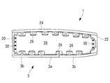
- FIG. 3 is a transverse sectional view taken along line AA in FIG. 2. It is the principal part disassembled perspective view which showed the laminated structure of the fiber sheet. It is a principal part top view of the 2nd layer in 1st Embodiment. It is a principal part top view of the 2nd layer in 2nd Embodiment.
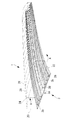
- FIG. 1 (a) shows a lower skin 3 of a main wing 1 of an aircraft.
- the lower surface outer plate 3 is formed of a composite material structure made of fiber reinforced plastic (FRP: Fiber Reinforced Plastics).
- FRP Fiber Reinforced Plastics
- the broken line shown in the figure shows the outline of the main wing 1 including flaps and slats.
- the lower surface outer plate 3 includes a front spar 20 and a rear spar 22 which are side surface erected from both ends in the width direction of the lower surface outer plate 3, and upper ends of the front spar 20 and the rear spar 22.
- a box-shaped torque box is formed together with the upper surface outer plate 24 that connects the two, and bears the load of the main wing 1.
- a plurality of stringers 26 are provided in the longitudinal direction of the main wing 1.
- the stringer 26 is a composite material made of FRP like the lower outer plate 3 and the like.
- Each stringer 26 is fixed to the inner surfaces of the lower surface outer plate 3 and the upper surface outer plate 24 and mainly bears the load in the longitudinal direction of the main wing 1.
- ribs 28 are provided so as to divide the internal space into a plurality of parts in the longitudinal direction.
- the ribs 28 have a plate shape extending in the width direction (direction orthogonal to the longitudinal direction) of the main wing 1, and a plurality of ribs 28 are arranged with a predetermined interval in the longitudinal direction.
- the front and rear end portions of each rib 28 are fixed to the front spar 20 and the rear spar 22 by predetermined fasteners 30 such as bolts and nuts, respectively.
- an access hole (hole) 5 is provided on the lower outer plate 3 for use in checking or assembling a fuel tank provided in the main wing 1 along the extending direction of the main wing 1.
- a plurality are formed at predetermined intervals.
- the lower outer plate 3 includes a peripheral region 3a positioned around each access hole 5 and another region 3b surrounding the peripheral region 3a, and is formed of an integral composite material.
- the peripheral region 3a is provided over a predetermined width d on both sides of the axis with a line along the extending direction of the main wing 1 passing through the center of each access hole 5 as an axis.
- the “width d” is the distance of the peripheral region in the direction orthogonal to the extending direction of the main wing 1.
- the other region 3b is located around the peripheral region 3a, and substantially the entire region other than the peripheral region 3a is defined as the existence range.
- the peripheral region 3a and the other region 3b constituting the lower surface outer plate 3 are a composite material mainly composed of carbon fiber reinforced plastic (CFRP: Carbon Fiber Reinforced Plastics).
- CFRP Carbon Fiber Reinforced Plastics
- the number of laminated layers of the composite material is determined by the strength to be borne, and is, for example, about several tens.
- the ratio of the orientation of the carbon fibers in the peripheral region 3a is different from that in the other region 3b, and when the extending direction of the main wing 1 is 0 °, it is ⁇ 30 ° or more ⁇ 60 ° between the adjacent holes 5 and 5
- the main component is ⁇ 45 °. That is, the orientation ratio of ⁇ 30 ° to ⁇ 60 °, preferably ⁇ 45 °, is larger than that of the other region 3b.
- each fiber direction is adjusted so that the ⁇ 45 ° orientation ratio is 70% or more.
- a plurality of fiber sheets are stacked and configured.
- the fiber in the 0 ° direction may be changed from carbon fiber to glass fiber (Glass fiber) or aramid fiber (Aramid fiber).
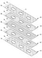
- FIG. 4 is an exploded perspective view of a main part illustrating a laminated structure of fiber sheets.
- the stacked structure in FIG. 4 is composed of a first layer 41 to a fifth layer 45.
- the positions of the hole 5, the peripheral region 3a, and the other region 3b in the first layer 41 to the fifth layer 45 correspond to each other in the vertical direction.
- the direction in which the holes 5 are arranged is 0 °.
- the first layer 41 is a layer in which fibers are oriented in the + 45 ° direction.
- the first layer 41 is formed by arranging + 45 ° fiber sheets over the peripheral region 3a and the other region 3b.
- the second layer 42 is a layer in which fibers are mainly oriented in the 0 ° direction.
- the second layer 42 is formed by disposing the peripheral region composite material in the peripheral region 3a and disposing the other region composite material in the other region 3b. Detailed arrangement of the composite material for the peripheral region and the composite material for other regions will be described later.
- the third layer 43 is a layer in which fibers are oriented in the 90 ° direction.
- the third layer 43 is formed by arranging 90 ° fiber sheets over the peripheral region 3a and the other region 3b.
- the fourth layer 44 is a layer in which fibers are mainly oriented in the 0 ° direction.
- the fourth layer 44 is formed by disposing the peripheral region composite material in the peripheral region 3a and disposing the other region composite material in the other region 3b.
- the fifth layer 45 is a layer in which fibers are oriented in the + 45 ° direction.
- the fifth layer 45 is formed by arranging + 45 ° fiber sheets over the peripheral region 3a and the other region 3b.
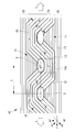
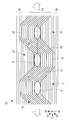
- FIG. 5 is a main part plan view of the second layer 42.
- the second layer 42 includes a plurality of holes 5 formed side by side along the direction t in which the main load is applied, a peripheral region 3 a around the hole 5, and a peripheral region 3 a. It is comprised from the other area
- the peripheral region 3a includes a first area 10 where the first peripheral region composite material is disposed and a second area 11 where the second peripheral region composite material is disposed.
- the first peripheral region composite material and the second peripheral region composite material are composite materials (composite material A) reinforced with continuous fibers aligned in the longitudinal direction.
- continuous fiber indicates a state in which the peripheral region 3 a is not cut in the t direction.
- the composite material A is a sheet-like prepreg or a semi-impregnated prepreg.
- the first area 10 is formed by meandering the composite material A by bending the composite material A so that the center line of the width W of the composite material A passes between the adjacent holes 5 and 5.
- the composite material A may be meandered to the target with a line passing through the centers of the plurality of holes 5 as an axis.
- the composite A may have a width W obtained by arranging a plurality of narrow prepregs.
- the width W may be a length that allows the gap between the adjacent holes 5 and 5 to be filled with the composite material A when the composite material A is meandered.
- the width W is the length of the composite material in the direction orthogonal to the orientation of the continuous fibers.
- the first area 10 includes an inclined portion 12 and a parallel portion 13.
- the inclined portions 12 and the parallel portions 13 are alternately arranged.
- FIG. 5 when changing from the inclined portion 12 to the parallel portion 13, the composite A is bent so that the fiber orientation is switched at a predetermined angle, but is bent so that the fiber orientation gradually changes so as to draw a curve. May be.
- the inclined portion 12 is located between the adjacent holes 5 and the continuous fibers in the composite A are oriented in the direction of ⁇ 30 ° to ⁇ 60 °, preferably ⁇ 45 °.
- the parallel portion 13 is disposed at a position including an extension line of the short diameter (diameter facing ⁇ 90 ° direction) of the hole 5.
- the parallel part 13 is good also at the position containing the outer edge 13a of the 1st area 10 in the area
- the parallel portion 13 is at least partially in contact with the hole 5.
- the second area 11 is a valley that is a bent portion of the meandering first area.
- the second area 11 is formed by arranging the second peripheral region composite material in the valley so that the fiber orientation is in the 0 ° direction.
- the fourth layer 44 has the same configuration as the second layer 42. However, it is preferable that the first area of the fourth layer 44 has a meandering shape in which the arrangement of the mountain and valley portions is opposite to that of the first area of the second layer 42. Specifically, assuming that the first area 10 in the second layer 42 has a meandering shape in which the composite material A repeats bending in the order of peaks and valleys, the first area in the fourth layer 44 is the composite material A. Is a meandering shape that repeats bending in the order of valley and peak. When the second layer 42 and the fourth layer 44 including the first area are stacked, the peak portion of the first area of the second layer 42 and the valley portion of the first area of the fourth layer 44 are paired vertically. Become.
- the peripheral region 3a is ⁇ 30 ° or more compared to the other region 3b.
- An orientation ratio of ⁇ 60 ° or less, preferably ⁇ 45 °, can be mainly used.
- the peripheral region 3a is mainly composed of fibers with an orientation of ⁇ 30 ° to ⁇ 60 °, preferably ⁇ 45 °, compared to the other regions 3b, and has a low rigidity with respect to a tensile load in the 0 ° direction. Because it is. Therefore, since only a small tensile load is applied to the peripheral area 3a compared to the other areas 3b, the required strength of the peripheral area 3a is reduced. That is, it is not necessary to provide a reinforcing laminate for increasing the thickness around the hole. For easy understanding, the reinforcing laminate 104 is also shown in FIG. In this way, the reinforcing laminate 104 is not necessary, and the weight can be reduced by this amount.
- the peripheral region 3a mainly has ⁇ 30 ° or more and ⁇ 60 ° or less, preferably ⁇ 45 °, so that the rigidity in the shear direction, that is, the torsional rigidity is enhanced. Therefore, the peripheral region 3a bears a torsional load without bearing an axial force (tensile load).
- the peripheral region 3a includes a first area 10 formed by meandering the composite material A reinforced with continuous fibers aligned in the longitudinal direction. Since the composite material A includes continuous fibers, the fibers are maintained in a continuous state even when bent. Since the fibers are continuous, the strength in the 0 ° direction can be improved as compared with the case where short fibers are used. By using a composite material reinforced with continuous fibers, there is no concern that a gap is generated at the boundary where the fiber orientation in the first area changes. Thereby, it becomes a composite material structure of higher precision than before.
- the first area 10 can be formed around a plurality of holes, so that the composite material A can be arranged by a machine and is efficient. Can be manufactured.
- the tensile rigidity in the 0 ° direction (one direction) is reduced, and a region allowing elongation in the tensile direction (and / or the compression direction) is realized. be able to.
- the fiber is oriented in the direction of ⁇ 30 ° or more and ⁇ 60 ° or less, preferably ⁇ 45 °, the strength in the shearing direction (direction orthogonal to one direction, that is, ⁇ 90 ° direction) Increases and torsional rigidity can be increased.
- the fiber direction in the peripheral region 3a can be aligned with the fiber direction in the adjacent other region 3b. Thereby, the intensity
- the boundary of the fiber sheets is shifted in the vertical direction by making the peak of the first area A of one layer and the valley of the first area B of another layer pair. be able to. Thereby, the risk of strength reduction in the ⁇ 90 ° direction can be dispersed.
- the composite structure according to the present embodiment has the same configuration as that of the first embodiment except that the range in which the parallel portion is provided is different.
- FIG. 6 the principal part top view of the 2nd layer 52 which concerns on this embodiment is shown.
- the parallel part 13 is arrange
- FIG. The length of the parallel portion is the same as the long diameter of the hole 5.
- the strength around the holes in the 0 ° direction can be improved. Since there is no boundary at which the fiber direction is switched in the ⁇ 90 ° direction of the hole, the strength around the hole in the ⁇ 90 ° direction can be improved.
- this invention demonstrated the application to the lower surface outer plate 3 of the main wing 1, this invention is not limited to this, If it is a composite material structure which has a hole, it can apply widely.
- the same configuration as that of the lower surface outer plate 3 may be applied to the upper surface outer plate constituting the torque box together with the lower surface outer plate 3.
- This embodiment can also be applied to a tail wing or the like.
- the above embodiment can also be applied to an aircraft fuselage in which a window hole is formed.
- the composite material structure of the present invention is not limited to an aircraft, and can be applied to, for example, ships and vehicles.
- CFRP carbon fiber reinforced plastic
- GFRP Glass Fiber Reinforced Plastic
- AFRP Aramid Fiber Reinforced Plastic
Landscapes
- Engineering & Computer Science (AREA)
- Mechanical Engineering (AREA)
- Aviation & Aerospace Engineering (AREA)
- Chemical & Material Sciences (AREA)
- Composite Materials (AREA)
- Textile Engineering (AREA)
- Moulding By Coating Moulds (AREA)
- Laminated Bodies (AREA)
- Compositions Of Macromolecular Compounds (AREA)
Abstract
Description
以下、本発明の一実施形態について、図1から図3を用いて説明する。
図1(a)には、航空機の主翼1の下面外板3が示されている。下面外板3は、繊維強化プラスチック(FRP:Fiber Reinforced Plastics)製の複合材構造体で形成されている。同図に示した破線は、フラップやスラット等を含む主翼1の外形線を示している。
ボックス構造とされた主翼1の内部には、その内部空間を長手方向において複数に分割するようにリブ28が設けられている。リブ28は、主翼1の幅方向(長手方向に直交する方向)にわたって延在した板状とされており、長手方向に所定間隔を有して複数配置されている。図3に示すように、各リブ28の前後の端部は、それぞれ、フロントスパー20及びリアスパー22に対してボルト・ナット等の所定のファスナ30によって固定されている。
下面外板3は、各アクセスホール5の周囲に位置する周縁領域3aと、この周縁領域3aを取り囲む他領域3bとから成り、一体の複合材料で形成されている。
飛行時、主翼1には、その先端が上向きに変位するように荷重が加わる。したがって、主翼1の下面外板3には、その延在方向(0°方向)に引張り荷重が加わる。0°方向の引張り荷重は、周縁領域3aではなく、下面外板3の他領域3bが主として負担する。なぜなら、周縁領域3aは、他領域3bに比べて±30°以上±60°以下、好ましくは±45°配向の繊維が主体とされており0°方向の引張り荷重に対して剛性が低い領域とされているからである。したがって、周縁領域3aには、他領域3bに比べて小さな引張り荷重しか加わらないので、周縁領域3aの必要強度が下がる。つまり、増厚のための強化用積層体を孔周りに設ける必要がない。理解の容易のために、図1(b)には、強化用積層体104が併せて示されている。このように、強化用積層体104が不要となるので、この分だけ軽量化することができる。
本実施形態に係る複合材構造体は、平行部を設ける範囲が異なる以外は第1実施形態と同様の構成である。
図6に、本実施形態に係る第2層52の要部平面図を示す。本実施形態において、平行部13は、孔5の長径(0°方向の直径)と並行する領域にわたって配置されている。平行部の長さは、孔5の長径と同じである。
例えば、下面外板3とともにトルクボックスを構成する上面外板に、下面外板3と同様の構成を適用しても良い。本実施形態は、尾翼などにも適用することができる。
3 下面外板(複合材構造体)
3a 周縁領域
3b 他領域
5 アクセスホール(孔)
10 第1エリア
11 第2エリア
12 傾斜部
13 平行部
13a (平行部の)外縁
20 フロントスパー
22 リアスパー
24 上面外板
26 ストリンガ
28 リブ
30 ファスナ
41 第1層
42 第2層
43 第3層
44 第4層
45 第5層
104 強化用積層体
Claims (18)
- 一方向に延在するとともに、複数の孔が前記一方向に間隔を空けて並べて形成された繊維強化プラスチック製の複合材とされ、前記一方向に引張り荷重および/または圧縮荷重が負荷される複合材構造体において、
前記孔の周縁領域は、長手方向に引き揃えられた連続繊維で強化された複合材が前記複合材の幅Wの中心線が隣合う孔と孔との間をぬうように屈曲し前記一方向に向かって蛇行してなる第1エリアを含み、
前記周縁領域の前記一方向における引張り剛性および/または圧縮剛性が、該周縁領域を取り囲む他領域の前記一方向における引張り剛性および/または圧縮剛性よりも小さい複合材構造体。 - 前記第1エリアは、前記一方向を0°とした場合に前記連続繊維が±30°以上±60°以下の方向を向く傾斜部を含み、
前記傾斜部が、隣合う孔と孔との間に配置されている請求項1に記載の複合材構造体。 - 前記第1エリアは、前記一方向を0°とした場合に前記連続繊維が±45°方向を向く傾斜部を含み、
前記傾斜部が、隣合う孔と孔との間に配置されている請求項1に記載の複合材構造体。 - 前記第1エリアは、前記連続繊維が0°方向を向くよう配置された平行部を含み、
前記平行部は、前記第1エリアの少なくとも前記孔の±90°方向を向く直径の延長線を含む位置に配置され、前記孔と接している請求項1から請求項3のいずれかに記載の複合材構造体。 - 前記平行部は、前記孔の0°方向の直径に並行する領域にある前記第1エリアの外縁を含む位置に配置されている請求項4に記載の複合材構造体。
- 1の前記傾斜部の連続繊維の向きが次の傾斜部の連続繊維の向きと直交する場合、前記幅Wは隣合う孔の中心間距離Lの1/√2以下と定義される請求項2から請求項5のいずれかに記載の複合材構造体。
- 前記平行部は、前記孔の0°方向の直径と並行する領域にある前記第1エリアである請求項4に記載の複合材構造体。
- 前記長手方向に引き揃えられた連続繊維で強化された複合材が山部、谷部の順に屈曲を繰り返す第1エリアAを含む層と、
前記長手方向に引き揃えられた連続繊維で強化された複合材が谷部、山部の順に屈曲を繰り返す第1エリアBを含む層と、
が、前記第1エリアAの山部と前記第1エリアBの谷部とが上下対になるよう積層されている請求項1から請求項7のいずれかに記載の複合材構造体。 - 前記孔は、航空機の翼の下面外板に形成されたアクセスホールである請求項1から請求項8のいずれかに記載の複合材構造体。
- 前記孔は、航空機の胴体の外板に形成された窓用孔である請求項1から請求項8のいずれかに記載の複合材構造体。
- 請求項9に記載の複合材構造体を備えている航空機翼。
- 請求項10に記載の複合材構造体を備えている航空機胴体。
- 一方向に延在するとともに、複数の孔が該一方向に間隔を空けて並べて形成された繊維強化プラスチック製の複合材とされ、前記一方向に引張り荷重および/または圧縮荷重が負荷される複合材構造体の製造方法において、
長手方向に引き揃えられた連続繊維で強化された複合材を該複合材の幅Wの中心線が隣合う孔と孔との間をぬうように屈曲させ前記一方向に向けて蛇行配置し、
前記孔の周縁領域の前記一方向における引張り剛性および/または圧縮剛性を、該周縁領域を取り囲む他領域の前記一方向における引張り剛性および/または圧縮剛性よりも小さくする複合材構造体の製造方法。 - 前記一方向を0°とした場合に、隣合う孔と孔との間で、前記連続繊維が±30°以上±60°以下の方向を向くよう前記長手方向に引き揃えられた連続繊維で強化された複合材を配置する請求項13に記載の複合材構造体の製造方法。
- 前記一方向を0°とした場合に、隣合う孔と孔との間で、前記連続繊維が±45°方向を向くよう前記長手方向に引き揃えられた連続繊維で強化された複合材を配置する請求項13に記載の複合材構造体の製造方法。
- 前記孔の±90°方向を向く直径の延長線を含む位置に、前記連続繊維が0°方向を向くよう前記長手方向に引き揃えられた連続繊維で強化された複合材を配置する請求項13から請求項15のいずれかに記載の複合材構造体の製造方法。
- 前記孔の0°方向の直径に並行する領域に、外縁において前記連続繊維が0°方向を向くよう前記長手方向に引き揃えられた連続繊維で強化された複合材を配置する請求項16に記載の複合材構造体の製造方法。
- 前記孔の0°方向の直径に並行する領域の前記連続繊維が0°方向を向くよう前記長手方向に引き揃えられた連続繊維で強化された複合材を配置する請求項16に記載の複合材構造体の製造方法。
Priority Applications (6)
| Application Number | Priority Date | Filing Date | Title |
|---|---|---|---|
| EP15770101.2A EP3103623B1 (en) | 2014-03-28 | 2015-03-17 | Composite material structure, aircraft wing and aircraft fuselage provided with same, and method for manufacturing composite material structure |
| US15/117,895 US10137664B2 (en) | 2014-03-28 | 2015-03-17 | Composite material structure, aircraft wing and aircraft fuselage provided with same, and method for manufacturing composite material structure |
| BR112016020521-9A BR112016020521A2 (pt) | 2014-03-28 | 2015-03-17 | Estrutura de material compósito, asa de avião e fuselagem de avião dotadas da mesma e método para fabricação de estrutura de material compósito |
| RU2016135195A RU2645500C1 (ru) | 2014-03-28 | 2015-03-17 | Конструкция из композиционного материала и содержащие ее крыло летательного аппарата и фюзеляж летательного аппарата, способ изготовления конструкции из композиционного материала |
| CA2940463A CA2940463C (en) | 2014-03-28 | 2015-03-17 | Composite material structure, aircraft wing and aircraft fuselage provided with same, and method for manufacturing composite material structure |
| CN201580009194.4A CN106029346B (zh) | 2014-03-28 | 2015-03-17 | 复合材料构造体、具有该复合材料构造体的航空机机翼及航空机机身、以及复合材料构造体的制造方法 |
Applications Claiming Priority (2)
| Application Number | Priority Date | Filing Date | Title |
|---|---|---|---|
| JP2014067920A JP6309324B2 (ja) | 2014-03-28 | 2014-03-28 | 複合材構造体、これを備えた航空機翼および航空機胴体、並びに複合材構造体の製造方法 |
| JP2014-067920 | 2014-03-28 |
Publications (1)
| Publication Number | Publication Date |
|---|---|
| WO2015146690A1 true WO2015146690A1 (ja) | 2015-10-01 |
Family
ID=54195213
Family Applications (1)
| Application Number | Title | Priority Date | Filing Date |
|---|---|---|---|
| PCT/JP2015/057786 Ceased WO2015146690A1 (ja) | 2014-03-28 | 2015-03-17 | 複合材構造体、これを備えた航空機翼および航空機胴体、並びに複合材構造体の製造方法 |
Country Status (8)
| Country | Link |
|---|---|
| US (1) | US10137664B2 (ja) |
| EP (1) | EP3103623B1 (ja) |
| JP (1) | JP6309324B2 (ja) |
| CN (1) | CN106029346B (ja) |
| BR (1) | BR112016020521A2 (ja) |
| CA (1) | CA2940463C (ja) |
| RU (1) | RU2645500C1 (ja) |
| WO (1) | WO2015146690A1 (ja) |
Cited By (1)
| Publication number | Priority date | Publication date | Assignee | Title |
|---|---|---|---|---|
| DE102016100191A1 (de) * | 2016-01-06 | 2017-07-06 | Wobben Properties Gmbh | Faserverbundbauteil und Strukturbauteil sowie Herstellungsverfahren |
Families Citing this family (9)
| Publication number | Priority date | Publication date | Assignee | Title |
|---|---|---|---|---|
| US10843788B2 (en) * | 2017-06-29 | 2020-11-24 | Textron Innovations Inc. | Damping structures for tiltrotor aircraft wings |
| FR3068912B1 (fr) * | 2017-07-11 | 2019-08-23 | Faurecia Automotive Industrie | Procede de fabrication d'une piece d'equipement de vehicule automobile et piece d'equipement associee |
| US11400685B2 (en) * | 2017-12-15 | 2022-08-02 | Unm Rainforest Innovations | Gradually recruited fiber reinforced polymer (FRP) composite |
| JP7112950B2 (ja) * | 2018-12-05 | 2022-08-04 | 三菱重工業株式会社 | 複合材の設計方法および複合材 |
| JP7198701B2 (ja) * | 2019-03-27 | 2023-01-04 | 日産自動車株式会社 | 繊維強化プラスチック複合材、繊維強化プラスチックプリフォーム、及び繊維強化プラスチック中間基材 |
| JP7390144B2 (ja) * | 2019-09-24 | 2023-12-01 | 三菱重工業株式会社 | 複合材の継手部材及び継手構造体 |
| GB2623100A (en) * | 2022-10-06 | 2024-04-10 | Bae Systems Plc | Aircraft wings |
| IT202300009465A1 (it) * | 2023-05-11 | 2024-11-11 | Leonardo Spa | Metodo di realizzazione di una struttura scatolata in materiale composito per aeromobili |
| GB2638210A (en) * | 2024-02-15 | 2025-08-20 | Airbus Operations Ltd | Composite structure |
Citations (3)
| Publication number | Priority date | Publication date | Assignee | Title |
|---|---|---|---|---|
| JPH01263030A (ja) * | 1988-04-15 | 1989-10-19 | Agency Of Ind Science & Technol | 複合材のファスナ継手 |
| JP2010524769A (ja) * | 2007-04-24 | 2010-07-22 | エアバス・オペレーションズ・ゲーエムベーハー | 部品を航空機胴体に取り付けるための取付配置構成品、航空機、および取付配置構成品を構成するための方法 |
| WO2012105691A1 (ja) * | 2011-02-04 | 2012-08-09 | 三菱重工業株式会社 | 複合材構造体、これを備えた航空機主翼および航空機胴体 |
Family Cites Families (26)
| Publication number | Priority date | Publication date | Assignee | Title |
|---|---|---|---|---|
| JPS5989842A (ja) * | 1982-11-12 | 1984-05-24 | Nhk Spring Co Ltd | Frp製ばね板 |
| DE3718676A1 (de) | 1987-06-04 | 1988-12-22 | Mtu Muenchen Gmbh | Formkoerper und verfahren zu seiner herstellung |
| NL8702487A (nl) * | 1987-10-19 | 1989-05-16 | Dsm Resins Bv | Werkwijze voor de vervaardiging van persprodukten. |
| JPH0462038A (ja) | 1990-06-25 | 1992-02-27 | Ryobi Ltd | 積層管およびその製造方法 |
| JPH0489326A (ja) | 1990-07-31 | 1992-03-23 | Matsushita Electric Ind Co Ltd | 光学ガラス成形体とその製造方法とその製造装置 |
| JPH04334696A (ja) | 1991-05-09 | 1992-11-20 | Mitsubishi Heavy Ind Ltd | 複合材製補強パネル |
| MX9206033A (es) * | 1991-10-22 | 1993-05-01 | Univ Brigham Young | Amortiguamiento mejorado en estructuras compuestas a traves de acoplamiento por esfuerzo. |
| DE4234038C2 (de) * | 1992-10-09 | 1997-07-03 | Daimler Benz Aerospace Airbus | Schalenbauteil aus Faserverbundwerkstoff |
| FR2699499B1 (fr) * | 1992-12-23 | 1995-03-10 | Eurocopter France | Pale en composite thermoplastique, notamment pour rotor arrière caréné d'hélicoptère, et son procédé de fabrication avec étape d'injection. |
| US5771680A (en) * | 1995-12-21 | 1998-06-30 | General Electric Company | Stiffened composite structures and method of making thereof |
| US20020028332A1 (en) * | 1996-10-09 | 2002-03-07 | Pratt William F. | Wavy composite tubular structures |
| US7906191B2 (en) * | 1997-11-14 | 2011-03-15 | William F. Pratt | Wavy composite structures |
| DE29813901U1 (de) * | 1998-07-23 | 1999-02-04 | Inst Konstruktion Und Verbundb | Verbundbauteil |
| RU2185964C1 (ru) * | 2001-01-19 | 2002-07-27 | Государственное предприятие "Всероссийский научно-исследовательский институт авиационных материалов" | Слоистый композиционный материал и изделие, выполненное из него |
| GB0117804D0 (en) * | 2001-07-21 | 2001-09-12 | Bae Systems Plc | Aircraft structural components |
| DE10153875A1 (de) * | 2001-11-02 | 2003-05-15 | Bpw Bergische Achsen Kg | Bauteil in langgestreckter Bauweise aus einem Faser-Kunststoff-Verbund |
| US9302427B2 (en) | 2005-03-31 | 2016-04-05 | The Boeing Company | Aeropspace structure including composite beam chord clamped between reinforcement plates |
| DE102008008386A1 (de) * | 2008-02-09 | 2009-08-13 | Airbus Deutschland Gmbh | Verfahren zur Herstellung eines FVW-Bauteils |
| JP5167953B2 (ja) | 2008-05-27 | 2013-03-21 | 東レ株式会社 | 積層基材、繊維強化プラスチック、およびそれらの製造方法 |
| CA2768957C (en) * | 2009-10-08 | 2014-07-29 | Mitsubishi Heavy Industries, Ltd. | Composite-material structure and aircraft main wing and aircraft fuselage provided with the same |
| JP2011084008A (ja) | 2009-10-16 | 2011-04-28 | Toyota Motor Corp | Frp積層体の成形方法 |
| JP5808111B2 (ja) | 2011-02-04 | 2015-11-10 | 三菱重工業株式会社 | 航空機用複合材構造体、これを備えた航空機主翼および航空機胴体 |
| US8616500B2 (en) | 2011-03-04 | 2013-12-31 | The Boeing Company | Diamond shaped window for composite and/or metallic airframe |
| JP6004669B2 (ja) * | 2012-02-29 | 2016-10-12 | 三菱重工業株式会社 | 複合材構造体、これを備えた航空機翼および航空機胴体、並びに複合材構造体の製造方法 |
| US9289949B2 (en) * | 2012-06-08 | 2016-03-22 | The Boeing Company | Optimized cross-ply orientation in composite laminates |
| DE102012221404A1 (de) * | 2012-11-22 | 2014-06-05 | Bayerische Motoren Werke Aktiengesellschaft | Aus einem Faserverbund bestehende Komponente, insbesondere für das Fahrwerk eines Kraftfahrzeuges |
-
2014
- 2014-03-28 JP JP2014067920A patent/JP6309324B2/ja active Active
-
2015
- 2015-03-17 CA CA2940463A patent/CA2940463C/en active Active
- 2015-03-17 BR BR112016020521-9A patent/BR112016020521A2/pt not_active IP Right Cessation
- 2015-03-17 RU RU2016135195A patent/RU2645500C1/ru active
- 2015-03-17 US US15/117,895 patent/US10137664B2/en active Active
- 2015-03-17 CN CN201580009194.4A patent/CN106029346B/zh not_active Expired - Fee Related
- 2015-03-17 WO PCT/JP2015/057786 patent/WO2015146690A1/ja not_active Ceased
- 2015-03-17 EP EP15770101.2A patent/EP3103623B1/en active Active
Patent Citations (3)
| Publication number | Priority date | Publication date | Assignee | Title |
|---|---|---|---|---|
| JPH01263030A (ja) * | 1988-04-15 | 1989-10-19 | Agency Of Ind Science & Technol | 複合材のファスナ継手 |
| JP2010524769A (ja) * | 2007-04-24 | 2010-07-22 | エアバス・オペレーションズ・ゲーエムベーハー | 部品を航空機胴体に取り付けるための取付配置構成品、航空機、および取付配置構成品を構成するための方法 |
| WO2012105691A1 (ja) * | 2011-02-04 | 2012-08-09 | 三菱重工業株式会社 | 複合材構造体、これを備えた航空機主翼および航空機胴体 |
Non-Patent Citations (1)
| Title |
|---|
| See also references of EP3103623A4 * |
Cited By (2)
| Publication number | Priority date | Publication date | Assignee | Title |
|---|---|---|---|---|
| DE102016100191A1 (de) * | 2016-01-06 | 2017-07-06 | Wobben Properties Gmbh | Faserverbundbauteil und Strukturbauteil sowie Herstellungsverfahren |
| US11285688B2 (en) | 2016-01-06 | 2022-03-29 | Wobben Properties Gmbh | Fiber composite component, structural component, and production method |
Also Published As
| Publication number | Publication date |
|---|---|
| CN106029346B (zh) | 2018-07-24 |
| BR112016020521A2 (pt) | 2021-08-24 |
| CN106029346A (zh) | 2016-10-12 |
| EP3103623A1 (en) | 2016-12-14 |
| JP6309324B2 (ja) | 2018-04-11 |
| EP3103623A4 (en) | 2017-07-26 |
| CA2940463A1 (en) | 2015-10-01 |
| RU2645500C1 (ru) | 2018-02-21 |
| US10137664B2 (en) | 2018-11-27 |
| EP3103623B1 (en) | 2021-09-08 |
| CA2940463C (en) | 2018-07-24 |
| JP2015189082A (ja) | 2015-11-02 |
| US20170008250A1 (en) | 2017-01-12 |
Similar Documents
| Publication | Publication Date | Title |
|---|---|---|
| JP6309324B2 (ja) | 複合材構造体、これを備えた航空機翼および航空機胴体、並びに複合材構造体の製造方法 | |
| JP6004669B2 (ja) | 複合材構造体、これを備えた航空機翼および航空機胴体、並びに複合材構造体の製造方法 | |
| JP5308533B2 (ja) | 複合材構造体、これを備えた航空機主翼および航空機胴体 | |
| JP5808111B2 (ja) | 航空機用複合材構造体、これを備えた航空機主翼および航空機胴体 | |
| JP5654055B2 (ja) | 複合材構造体、これを備えた航空機主翼および航空機胴体 | |
| JP5808112B2 (ja) | 複合材構造体およびこれを備えた航空機主翼 | |
| US10000273B2 (en) | Passive load alleviation for a fiber reinforced wing box of an aircraft with a stiffened shell structure | |
| WO2012131137A2 (es) | Fuselaje de aeronave con cuadernas altamente resistentes | |
| US20180281923A1 (en) | Skin panel of composite material having an internal grid | |
| US10745098B2 (en) | Energy-absorbing under-floor airframe | |
| JP2022150610A (ja) | 異方性複合材積層構造の設計方法 |
Legal Events
| Date | Code | Title | Description |
|---|---|---|---|
| 121 | Ep: the epo has been informed by wipo that ep was designated in this application |
Ref document number: 15770101 Country of ref document: EP Kind code of ref document: A1 |
|
| WWE | Wipo information: entry into national phase |
Ref document number: 15117895 Country of ref document: US |
|
| ENP | Entry into the national phase |
Ref document number: 2940463 Country of ref document: CA |
|
| REEP | Request for entry into the european phase |
Ref document number: 2015770101 Country of ref document: EP |
|
| WWE | Wipo information: entry into national phase |
Ref document number: 2015770101 Country of ref document: EP |
|
| NENP | Non-entry into the national phase |
Ref country code: DE |
|
| ENP | Entry into the national phase |
Ref document number: 2016135195 Country of ref document: RU Kind code of ref document: A |
|
| REG | Reference to national code |
Ref country code: BR Ref legal event code: B01A Ref document number: 112016020521 Country of ref document: BR |
|
| ENP | Entry into the national phase |
Ref document number: 112016020521 Country of ref document: BR Kind code of ref document: A2 Effective date: 20160905 |
|
| REG | Reference to national code |
Ref country code: BR Ref legal event code: B01E Ref document number: 112016020521 Country of ref document: BR Kind code of ref document: A2 Free format text: APRESENTE A TRADUCAO SIMPLES DA FOLHA DE ROSTO DA CERTIDAO DE DEPOSITO DA PRIORIDADE REIVINDICADA; OU DECLARACAO DE QUE OS DADOS DO PEDIDO INTERNACIONAL ESTAO FIELMENTE CONTIDOS NA PRIORIDADE REIVINDICADA, CONTENDO TODOS OS DADOS IDENTIFICADORES (NUMERO DA PRIORIDADE, DATA, DEPOSITANTE E INVENTORES), CONFORME O PARAGRAFO UNICO DO ART. 25 DA RESOLUCAO 77/2013. CABE SALIENTAR NAO FOI POSSIVEL INDIVIDUALIZAR OS TITULARES DA CITADA PRIORIDADE, INFORMACAO NECESSARIA PARA O EXAME DA CESSAO DO DOCUMENTO DE PRIORIDADE, SE FOR O CASO. |
|
| ENP | Entry into the national phase |
Ref document number: 112016020521 Country of ref document: BR Kind code of ref document: A2 Effective date: 20160905 |