WO2015146902A1 - Structure latérale de caisse de véhicule - Google Patents
Structure latérale de caisse de véhicule Download PDFInfo
- Publication number
- WO2015146902A1 WO2015146902A1 PCT/JP2015/058719 JP2015058719W WO2015146902A1 WO 2015146902 A1 WO2015146902 A1 WO 2015146902A1 JP 2015058719 W JP2015058719 W JP 2015058719W WO 2015146902 A1 WO2015146902 A1 WO 2015146902A1
- Authority
- WO
- WIPO (PCT)
- Prior art keywords
- stiffener
- wall
- pillar
- reinforcing member
- reinforcing
- Prior art date
- Legal status (The legal status is an assumption and is not a legal conclusion. Google has not performed a legal analysis and makes no representation as to the accuracy of the status listed.)
- Ceased
Links
Images







Classifications
-
- B—PERFORMING OPERATIONS; TRANSPORTING
- B62—LAND VEHICLES FOR TRAVELLING OTHERWISE THAN ON RAILS
- B62D—MOTOR VEHICLES; TRAILERS
- B62D25/00—Superstructure or monocoque structure sub-units; Parts or details thereof not otherwise provided for
- B62D25/04—Door pillars ; windshield pillars
-
- B—PERFORMING OPERATIONS; TRANSPORTING
- B60—VEHICLES IN GENERAL
- B60J—WINDOWS, WINDSCREENS, NON-FIXED ROOFS, DOORS, OR SIMILAR DEVICES FOR VEHICLES; REMOVABLE EXTERNAL PROTECTIVE COVERINGS SPECIALLY ADAPTED FOR VEHICLES
- B60J5/00—Doors
- B60J5/04—Doors arranged at the vehicle sides
- B60J5/047—Doors arranged at the vehicle sides characterised by the opening or closing movement
-
- B—PERFORMING OPERATIONS; TRANSPORTING
- B62—LAND VEHICLES FOR TRAVELLING OTHERWISE THAN ON RAILS
- B62D—MOTOR VEHICLES; TRAILERS
- B62D21/00—Understructures, i.e. chassis frame on which a vehicle body may be mounted
- B62D21/15—Understructures, i.e. chassis frame on which a vehicle body may be mounted having impact absorbing means, e.g. a frame designed to permanently or temporarily change shape or dimension upon impact with another body
- B62D21/157—Understructures, i.e. chassis frame on which a vehicle body may be mounted having impact absorbing means, e.g. a frame designed to permanently or temporarily change shape or dimension upon impact with another body for side impacts
-
- B—PERFORMING OPERATIONS; TRANSPORTING
- B60—VEHICLES IN GENERAL
- B60Y—INDEXING SCHEME RELATING TO ASPECTS CROSS-CUTTING VEHICLE TECHNOLOGY
- B60Y2306/00—Other features of vehicle sub-units
- B60Y2306/01—Reducing damages in case of crash, e.g. by improving battery protection
-
- B—PERFORMING OPERATIONS; TRANSPORTING
- B60—VEHICLES IN GENERAL
- B60Y—INDEXING SCHEME RELATING TO ASPECTS CROSS-CUTTING VEHICLE TECHNOLOGY
- B60Y2410/00—Constructional features of vehicle sub-units
- B60Y2410/12—Production or manufacturing of vehicle parts
- B60Y2410/124—Welded parts
Definitions
- the present invention relates to a vehicle body side portion structure including a center pillar that extends in the vertical direction at the vehicle body side portion.
- the center pillar is generally formed in a hollow shape having a substantially rectangular cross section by a pillar outer, a pillar inner, and a pillar stiffener.
- the hinge mounting portion of the center pillar bulges outward from the other part in the vehicle width direction, and the side door is mounted on the hinge mounting portion via the door hinge.
- a gap is formed between the other part of the center pillar and the side door by the hinge mounting portion bulging outward from the other part in the vehicle width direction.
- a pillar gap is formed between the pillar outer and the pillar stiffener in order to coat each pillar facing surface of the pillar outer and the pillar stiffener with the electrodeposition coating liquid.
- a hinge mounting portion is formed by the pillar outer and the pillar stiffener, and the door hinge is fastened to the hinge mounting portion by a bolt and a nut.
- the center pillar has a front flange and a rear flange on the pillar outer, the pillar inner, and the pillar stiffener, respectively.
- the center pillar is formed in a hollow shape having a substantially rectangular cross section by joining in a state where the front flanges are overlapped and joining in a state where the rear flanges are overlapped. Therefore, when an impact load is input to the center pillar from the outside in the vehicle width direction, the center pillar is deformed so as to be crushed inward in the vehicle width direction and to extend in the longitudinal direction of the vehicle body. It is conceivable that the space in the passenger compartment is reduced by the center pillar being crushed inward in the vehicle width direction. Furthermore, it is conceivable that stress is concentrated on the joint portion between the front flange and the rear flange of the center pillar when the center pillar is crushed, and a device for ensuring the rigidity of the center pillar is required.
- the invention according to claim 1 includes a center pillar extending in the vertical direction on the side of the vehicle body, the center pillar being joined to the pillar inner from the outside in the vehicle width direction, and a pillar inner provided on the inner side in the vehicle width direction.
- a pillar stiffener having a portion formed in a substantially U-shaped cross section so as to form a closed cross-section with the pillar inner, and an inner reinforcing member disposed in the closed cross-section between the pillar stiffener and the pillar inner.
- the pillar inner includes an inner inner wall disposed on the inner side in the vehicle width direction, an inner front wall and an inner rear wall extending outward in the vehicle width direction from an end on the vehicle body front-rear side of the inner inner wall, and the inner front wall.
- An inner front flange that extends to the front side of the vehicle body and is joined to the pillar stiffener, and extends from the inner rear wall to the rear side of the vehicle body, the pillar An inner rear flange joined to the tiffener is formed into a substantially hat-shaped cross section, and the inner reinforcing member includes an inner reinforcing outer wall disposed on the outer side in the vehicle width direction, and an end of the inner reinforcing outer wall on the vehicle front-rear side An inner reinforcement front wall and an inner reinforcement rear wall extending inward in the vehicle width direction from the inner reinforcement front flange extending from the inner reinforcement front wall to the vehicle body front side, and an inner reinforcement rear flange extending from the inner reinforcement rear wall to the vehicle body rear side.
- a vehicle body side part structure is provided in which the cross section is formed in a substantially hat shape, and the flange before inner reinforcement and the flange after inner reinforcement are joined to the inner inner wall of the pillar inner.
- the center pillar includes a stiffener reinforcing member that is formed separately from the inner reinforcing member, and extends in a vertical direction on the outer side in the vehicle width direction than the inner reinforcing member.
- the reinforcing member is joined to the inner side in the vehicle width direction of the pillar stiffener, and is disposed so as to overlap the inner reinforcing member in the vehicle width direction.
- the inner reinforcing member was formed in a substantially hat-shaped cross section, and the inner reinforcing flange and the inner reinforcing flange of the inner reinforcing member were joined to the inner wall of the pillar inner. Therefore, since the width dimension of the inner reinforcing member in the longitudinal direction of the vehicle body is suppressed, it is difficult to bring the ridge line (corner portion) of the inner reinforcing member close to the ridge line of the pillar stiffener. For this reason, when an impact load is input to the pillar stiffener from the outside in the vehicle width direction, the input impact load cannot be quickly supported by the ridgeline of the inner reinforcing member.
- the flange before the inner reinforcement and the flange after the inner reinforcement are arranged inside the inner reinforcement member. It is possible to do. However, if each flange is disposed inside the inner reinforcing member, the interval between the flanges becomes smaller than the width dimension of the inner reinforcing member, and the inner reinforcing member has a so-called undercut shape. For this reason, the press die for press-molding the inner reinforcing member cannot be removed from the inner reinforcing member, and the inner reinforcing member cannot be press-molded.
- a stiffener reinforcing member is provided on the outer side in the vehicle width direction than the inner reinforcing member. Further, the stiffener reinforcing member is joined to the inner side of the pillar stiffener in the vehicle width direction, and the stiffener reinforcing member is arranged to overlap the inner reinforcing member in the vehicle width direction.
- the stiffener reinforcing member includes a stiffener reinforcing outer wall disposed on an outer side in the vehicle width direction, and a stiffener extending inward in the vehicle width direction from an end portion on the vehicle body front-rear side of the stiffener reinforcing outer wall.
- the inner wall is formed in the substantially U-shaped cross section formed by the stiffener reinforcing member, and the vehicle body as it goes downward.
- An inner reinforcing cross-section enlarged portion having a large width dimension in the front-rear direction is provided, and the stiffener reinforcing front wall and the stiffener reinforcing rear wall are arranged in a portion facing the inner reinforcing cross-sectional enlarged portion at a vehicle width compared to other portions.
- An overhanging reduction portion having a small overhanging dimension is provided.
- the stiffener reinforcing member is formed to have a substantially constant width dimension from above to below along the pillar stiffener.
- the inner reinforcing member includes an inner reinforcing cross-sectional enlarged portion whose width dimension in the longitudinal direction of the vehicle body increases toward the lower side. For this reason, it is conceivable that the stiffener reinforcing member hits the inner reinforcing cross-section enlarged portion. Therefore, in the third aspect of the present invention, at the portion facing the inner reinforcing cross-section enlarged portion, the overhanging reduction portion is provided on the stiffener reinforcement front wall and the stiffener reinforcement rear wall, and the overhanging size of the overhang reduction portion is formed small.
- the pillar stiffener includes a stiffener outer wall that forms a wall portion on the outer side in the vehicle width direction, and the stiffener outer wall is disposed at a predetermined interval from the stiffener reinforcing member.
- the stiffener reinforcing outer wall is joined to the general surface on the upper and lower sides of the hinge mounting surface, and is disposed with a gap larger than the predetermined interval between the hinge mounting surface and the hinge mounting surface.
- the stiffener reinforcement front wall and the stiffener reinforcement rear wall are overhangs having a large overhang dimension in a portion facing the continuous surface of the pillar stiffener as compared with other portions.
- An enlargement section is provided.
- the hinge mounting surface of the stiffener outer wall bulges outward in the vehicle width direction, and the hinge mounting surface and the general surface are continuous with each other. Therefore, the ridge line of the continuous surface is extended so as to be inclined with respect to the vertical direction (that is, the ridge line of the general surface and the ridge line of the hinge mounting surface). For this reason, it is conceivable that the continuous surface has lower rigidity and strength than other portions of the general surface and the hinge mounting surface. Therefore, in claim 5, the stiffener reinforcement front wall and the stiffener reinforcement rear wall are provided with overhanging enlarged portions. The overhanging enlarged portion is disposed at a portion facing the continuous surface of the stiffener outer wall, and the overhanging dimension is formed larger than that of other portions.
- a nut for mounting the door hinge is disposed in the gap formed between the hinge mounting surface and the stiffener reinforcing outer wall.
- a gap is formed between the pillar stiffener and the stiffener reinforcing member in order to coat the opposing surfaces of the pillar stiffener and the stiffener reinforcing member with the electrodeposition coating liquid. Therefore, when the door hinge is fastened to the pillar stiffener and the stiffener reinforcing member with a bolt and a nut, a gap is interposed between the bolt and the nut. For this reason, it is difficult to secure the tightening torque of the bolt within a specified range, and it becomes difficult to manage the tightening torque.
- the nut is arranged in a gap formed between the hinge mounting surface of the pillar stiffener and the stiffener reinforcing outer wall of the stiffener reinforcing member.
- the stiffener reinforcing member is formed with a through-hole avoiding interference of a bolt fastened to the nut at a portion facing the nut, and the door hinge is formed by the bolt and the nut. Is attached to the hinge mounting surface.
- a closed cross section is formed by the pillar stiffener and the pillar inner, and the inner reinforcing member is disposed in the closed cross section.
- the pillar inner is formed in a substantially hat shape so as to bulge inward in the vehicle width direction
- the inner reinforcing member is formed in a substantially hat shape so as to bulge outward in the vehicle width direction.
- the flange before the inner reinforcement and the flange after the inner reinforcement of the inner reinforcing member were joined to the inner wall of the pillar inner. The inner reinforcing member bulges outward in the vehicle width direction (that is, on the pillar stiffener side).
- the pillar stiffener When an impact load is input to the pillar stiffener from the outside in the vehicle width direction, the pillar stiffener is deformed inward in the vehicle width direction and hits the inner reinforcing member. Therefore, the impact load input to the pillar stiffener is transmitted to the inner front flange and the inner rear flange of the pillar inner, and further to the inner wall of the pillar inner through the inner reinforcing member. As a result, the impact load input to the pillar stiffener can be distributed to the inner front flange, the inner rear flange, and the inner wall of the inner pillar so that it can be suitably absorbed by the center pillar, and the shock absorbing performance of the center pillar can be enhanced.
- the inner reinforcing member is bulged outward in the vehicle width direction. Therefore, the pillar stiffener that is deformed toward the vehicle width center side by the impact load input from the outside in the vehicle width direction hits the inner reinforcing member and is transmitted to the inner reinforcing member, whereby the impact load can be supported by the inner reinforcing member. Thereby, it can suppress that a center pillar compresses and deforms inside a vehicle width direction, and can suppress that the space of a vehicle interior decreases.
- the impact load input to the pillar stiffener is distributed to the inner front flange and inner rear flange of the pillar inner and the inner inner wall of the pillar inner. Therefore, the load transmitted to the inner front flange and the inner rear flange of the pillar inner can be suppressed. Thereby, strength is maintained at the flange joint portion of the center pillar, and the rigidity of the center pillar is ensured.
- the stiffener reinforcement member was provided in the vehicle width direction outer side rather than the inner reinforcement member. Further, the stiffener reinforcing member is joined to the inner side of the pillar stiffener in the vehicle width direction, and the stiffener reinforcing member is arranged to overlap the inner reinforcing member in the vehicle width direction. That is, a stiffener reinforcing member separate from the inner reinforcing member is provided, and the stiffener reinforcing member is interposed between the pillar stiffener and the inner reinforcing member so as to overlap in the vehicle width direction. Therefore, the ridge line of the stiffener reinforcing member can be brought close to the ridge line of the pillar stiffener.
- the flange before inner reinforcement and the flange after inner reinforcement of the inner reinforcement member can be sufficiently secured, and each flange can be firmly joined to the inner wall of the pillar inner by spot welding.
- the ridge line of the stiffener reinforcing member is brought close to the ridge line of the pillar stiffener.
- the two members on the outer side of the vehicle are integrally joined to the outer assembly portion.
- the two members on the passenger compartment side are integrally joined to the inner assembly portion.
- the center pillar is joined to the closed cross section by joining the pillar stiffener of the outer assembly part and the pillar inner of the inner assembly part.
- the stiffener reinforcing member is disposed so as to overlap the inner reinforcing member in the vehicle width direction. Therefore, the impact load input to the pillar stiffener can be quickly transmitted to the inner reinforcing member via the stiffener reinforcing member. Thereby, the impact load input to the pillar stiffener can be suitably absorbed by the center pillar, and the impact absorption performance of the center pillar can be enhanced.
- the overhanging reduction portion is provided on the stiffener reinforcement front wall and the stiffener reinforcement rear wall, and the overhanging size of the overhang reduction portion is formed small. Therefore, it is possible to prevent the inner reinforcing member from hitting the stiffener reinforcing front wall and the stiffener reinforcing rear wall. Thereby, when determining the shape of a stiffener reinforcement member and an inner reinforcement member, the freedom degree of design can be raised.
- the front stiffener reinforcement wall and the rear stiffener reinforcement rear wall are provided with an overhang reduction portion, and the overhang dimension is formed small only in the overhang reduction portion. Therefore, the overhang dimension can be increased in substantially the entire region of the stiffener reinforcing member. As a result, the cross-sectional shape can be increased in substantially the entire region of the stiffener reinforcing member, and the rigidity and strength of the stiffener reinforcing member can be sufficiently ensured.
- the stiffener reinforcement outer wall of the stiffener reinforcement member was joined to the general surface on the upper and lower sides of the hinge mounting surface, and was arranged with a large gap between the hinge mounting surface. Therefore, it is not necessary to bulge the portion of the stiffener reinforcing outer wall facing the hinge mounting surface outward in the vehicle width direction unlike the stiffener outer wall.
- the ridgeline of a stiffener reinforcement member can be extended on a substantially straight line in the up-down direction, and rigidity can be ensured in the whole area of the ridgeline. Therefore, the rigidity and strength of the stiffener reinforcing member, that is, the center pillar can be secured.
- projection expansion part was provided in the stiffener reinforcement front wall and the stiffener reinforcement rear wall.
- the overhanging enlarged portion is disposed at a portion facing the continuous surface of the stiffener outer wall, and the overhanging dimension is formed larger than that of other portions. Therefore, the rigidity and strength of the overhanging enlarged portion can be made higher than those of other portions. Thereby, the continuous surface whose rigidity and strength are lower than those of the general surface and the hinge mounting surface can be reinforced by the overhanging enlarged portion, and the rigidity and strength of the center pillar can be secured.
- the continuous surface of the stiffener outer wall is provided in the vicinity of the hinge mounting surface (that is, the door hinge). Therefore, the impact load is input from the door hinge to the continuous surface at an early stage. Thereby, the impact load input to the continuous surface can be suitably supported by reinforcing the continuous surface with the overhanging enlarged portion.
- a nut was arrange
- a through hole is formed in a portion of the stiffener reinforcing member facing the nut. It is possible to avoid the bolt from interfering with the stiffener reinforcing member at the through hole. As a result, the bolt tightening torque can be more easily secured within the specified range.
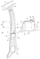
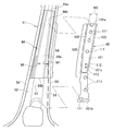
- FIG. 3 is an exploded perspective view showing a left center pillar provided in the vehicle body side part structure of FIG. 2.
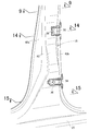
- FIG. 3 is an enlarged view of part 3 of FIG.
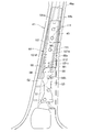
- FIG. 4 is a front view showing the left center pillar of FIG. 3 in a partially broken state.
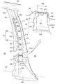
- It is a perspective view which shows the inner assembly
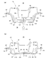
- FIG. 9 is a sectional view taken along line 9-9 of FIG. It is a front view which shows the state which decomposed
- FIG. 6 is a side view showing a state in which a stiffener reinforcing member is superimposed on the inner assembly portion of FIG. 5. It is a side view which shows the state which separated the stiffener reinforcement member from the inner assembly part of FIG.
- FIG. 13 is an enlarged view of 13 parts in FIG. 10.
- FIG. 14 is a sectional view taken along line 14-14 of FIG.
- FIG. 15 is a sectional view taken along line 15-15 in FIG.
- the vehicle body side part structure 10 will be described. As shown in FIG. 1, the vehicle body side structure 10 is erected upward from the middle in the longitudinal direction of the left and right side sills 12, 13 that extend in the longitudinal direction of the vehicle body on the left and right sides of the lower part of the vehicle body.
- the vehicle body side structure 10 is a substantially bilaterally symmetric member.
- the left side member will be described and description of the right side member will be omitted.
- the left side sill 12 includes a sill stiffener 24 that extends in the longitudinal direction of the vehicle body, and a sill outer 25 that extends along the sill stiffener 24.
- the left roof side rail 18 includes a rail inner 27 that extends in the vehicle longitudinal direction, a rail stiffener 28 that extends along the rail inner 27, and a rail outer 29 that extends along the rail stiffener 28.
- the left center pillar 15 is extended in the vertical direction so as to connect the central portion 12a of the left side sill 12 and the central portion 18a of the left roof side rail 18.
- the left center pillar 15 is provided in the left vehicle body side part 11, and the rear side door 31 is supported by the left center pillar 15 so that opening and closing is possible.
- the upper door hinge 33 and the lower door hinge 34 are attached to the left center pillar 15 with bolts 36 and nuts 37.
- the front end portion 31 a of the rear side door 31 is attached to the upper door hinge 33 and the lower door hinge 34. Accordingly, the rear side door 31 is rotatably supported by the left center pillar 15 via the upper door hinge 33 and the lower door hinge 34.
- the left center pillar 15 is joined to the pillar inner 41 provided on the inner side in the vehicle width direction (hereinafter referred to as the vehicle compartment 38 side), the pillar stiffener 42 joined to the pillar inner 41, and the pillar stiffener 42.
- a pillar outer 43, an inner reinforcing member 44 joined to the pillar inner 41, and a stiffener reinforcing member 45 joined to the pillar stiffener 42 are provided.
- the lower end portion 41 a of the pillar inner 41 is joined to the sill stiffener 24 (see FIG. 2), and the upper end portion 41 b of the pillar inner 41 is joined to the rail inner 27. Therefore, the pillar inner 41 extends in the up-down direction in a state of facing the vehicle compartment 38.
- An inner reinforcing member 44 is joined to the pillar inner 41 from the outside in the vehicle width direction (hereinafter referred to as the vehicle outside 39 side).
- the lower end portion 42 a of the pillar stiffener 42 is joined to the sill stiffener 24. Further, the upper end portion 42 b of the pillar stiffener 42 is joined to the rail stiffener 28. Therefore, the pillar stiffener 42 is extended in the up-down direction in a state of facing the pillar inner 41 (see FIG. 2) on the vehicle exterior 39 side. A stiffener reinforcing member 45 is joined to the pillar stiffener 42 from the vehicle compartment 38 side.
- the pillar stiffener 42 is joined to the pillar inner 41 from the outside 39 side in a state where the inner reinforcing member 44 is joined to the pillar inner 41 and the stiffener reinforcing member 45 is joined to the pillar stiffener 42. Thereby, the inner reinforcing member 44 and the stiffener reinforcing member 45 are provided between the pillar inner 41 and the pillar stiffener 42.
- the pillar outer 43 is joined to the pillar stiffener 42 from the vehicle exterior 39 side.
- the pillar outer 43 is integrally formed with the sill outer 25, the rail outer 29, and the like.
- the outer panel 23 is formed by the pillar outer 43, the sill outer 25, the rail outer 29, and the like.
- the pillar outer 43 is joined to the pillar stiffener 42 and the pillar inner 41 from the outside 39 side. Therefore, the pillar outer 43 extends in the up-down direction in a state of facing the pillar stiffener 42.
- the pillar inner 41 has an inner inner wall 51, an inner front wall 52, an inner rear wall 53, an inner front flange 54 and an inner rear flange 55.
- the inner inner wall 51 is disposed on the vehicle compartment 38 side, and has an inner convex portion 51a at the center in the longitudinal direction of the vehicle body.
- the inner convex portion 51a bulges toward the vehicle exterior 39 side.
- the inner front wall 52 is bent so as to extend from the front end portion (end portion on the vehicle body front side) 51b of the inner inner wall 51 to the vehicle exterior 39 side.
- the inner rear wall 53 is bent so as to extend from the rear end portion (end portion on the rear side of the vehicle body) 51c of the inner inner wall 51 to the vehicle exterior 39 side.
- the inner front flange 54 is bent so as to extend from the outer end 52a of the inner front wall 52 to the front side of the vehicle body.
- the inner rear flange 55 is bent so as to extend from the outer end 53a of the inner rear wall 53 to the vehicle body rear side.
- Pillar inner 41 is formed in a substantially hat-shaped cross section by inner inner wall 51, inner front wall 52, inner rear wall 53, inner front flange 54, and inner rear flange 55. Further, the inner inner wall 51, the inner front wall 52, and the inner rear wall 53 are formed in a substantially U-shaped cross section. Sites 51, 52, and 53 having a substantially U-shaped cross section are bulged toward the passenger compartment 38 side.
- the pillar stiffener 42 includes a stiffener outer wall 61, a stiffener front wall 62, a stiffener rear wall 63, a stiffener front flange 64, and a stiffener rear flange 65.
- the stiffener outer wall 61 is a part that forms a wall portion on the vehicle exterior 39 side.
- the stiffener front wall 62 is bent so as to extend from the front end portion 61 a of the stiffener outer wall 61 to the vehicle compartment 38 side.
- the stiffener rear wall 63 is bent so as to extend from the rear end portion 61b of the stiffener outer wall 61 to the vehicle compartment 38 side.
- the stiffener front flange 64 is bent so as to extend from the inner end 62a of the stiffener front wall 62 to the front side of the vehicle body.
- the stiffener rear flange 65 is bent so as to extend from the inner end 63a of the stiffener rear wall 63 to the vehicle body rear side.
- the pillar stiffener 42 is formed in a substantially hat shape by the stiffener outer wall 61, the stiffener front wall 62, the stiffener rear wall 63, the stiffener front flange 64, and the stiffener rear flange 65.
- the stiffener outer wall 61, the stiffener front wall 62, and the stiffener rear wall 63 are formed in a substantially U-shaped cross section. Sites 61, 62, and 63 having a substantially U-shaped cross section are bulged toward the outside 39 of the vehicle.
- a front ridge line 67 is formed at the front end portion 61 a of the stiffener outer wall 61, and a rear ridge line 68 is formed at the rear end portion 61 b of the stiffener outer wall 61.
- the front ridge line 67 is a corner portion formed at the front end portion 61a where the stiffener outer wall 61 and the stiffener front wall 62 intersect so as to protrude toward the vehicle exterior 39 side.
- the rear ridge line 68 is a corner portion formed at the rear end portion 61b where the stiffener outer wall 61 and the stiffener rear wall 63 intersect so as to protrude toward the vehicle exterior 39 side.
- the inner front flange 54 of the pillar inner 41, the stiffener front flange 64 of the pillar stiffener 42, and the outer front flange 43a of the pillar outer 43 are joined by spot welding.
- a front flange joint portion 47 is formed by the joined front flanges 54, 64, and 43a.
- the inner rear flange 55 of the pillar inner 41, the rear stiffener flange 65 of the pillar stiffener 42, and the outer rear flange 43b of the pillar outer 43 are joined by spot welding.
- a rear flange joint portion 48 is formed by the joined rear flanges 55, 65, and 43b.
- pillar closed cross section having a substantially rectangular cross section is formed between the pillar inner 41 and the pillar stiffener 42 in a hollow shape.
- a general surface 71, an upper hinge mounting surface 72, a lower hinge mounting surface 73, and a continuous surface 74 are formed on the stiffener outer wall 61 of the pillar stiffener 42.
- the upper hinge mounting surface 72 and the lower hinge mounting surface 73 are similar parts, respectively.
- the upper hinge mounting surface 72 will be described and the description of the lower hinge mounting surface 73 will be omitted.
- the general surface 71 is a portion that is disposed on the stiffener reinforcement outer wall 101 of the stiffener reinforcement member 45 at a predetermined interval S1 on the vehicle exterior 39 side and extends in the vertical direction.
- the upper hinge mounting surface 72 is a portion that bulges toward the vehicle exterior 39 side relative to the general surface 71 and extends in the vertical direction.
- the upper door hinge 33 is attached to the upper hinge attachment surface 72.
- the rear side door 31 (see FIG. 1) is supported on the upper hinge mounting surface 72 via the upper door hinge 33.
- the continuous surface 74 is a portion extending in an inclined manner so as to be continuous between the upper hinge mounting surface 72 and the general surface 71.
- the inner reinforcing member 44 includes an inner reinforcing outer wall 81, an inner reinforcing front wall 82, an inner reinforcing rear wall 83, an inner reinforcing front flange 84, and an inner reinforcing post flange 85.
- the inner reinforcing member 44 is disposed in a pillar closed section 49 between the pillar inner 41 and the pillar stiffener 42.
- the inner reinforcing outer wall 81 is disposed on the vehicle outer side 39 from the inner inner wall 51 and on the vehicle compartment 38 side from the stiffener reinforcing member 45 (specifically, the stiffener reinforcing outer wall 101).
- the inner reinforcing member 44 extends in the vertical direction along the pillar inner 41, and includes an inner reinforcing cross-sectional enlarged portion 88 in the lower part.
- the inner reinforcing cross-section enlarged portion 88 is formed such that the width dimension W1 in the vehicle longitudinal direction increases from the upper end portion 88a toward the lower end portion 88b.
- the inner reinforcing front wall 82 is bent so as to extend inward in the vehicle width direction from the front end portion (end portion on the vehicle body front side) 81 b of the inner reinforcing outer wall 81.
- the inner reinforcing rear wall 83 is bent so as to extend inward in the vehicle width direction from the rear end portion (end portion on the rear side of the vehicle body) 81c of the inner reinforcing outer wall 81.
- the inner reinforcing front flange 84 is bent so as to extend from the inner end 82a of the inner reinforcing front wall 82 to the front side of the vehicle body.
- the inner reinforcing post-flange 85 is bent so as to extend from the inner end 83a of the inner reinforcing post wall 83 to the vehicle body rear side.
- the inner reinforcing member 44 is formed in a substantially hat-shaped cross section by the inner reinforcing outer wall 81, the inner reinforcing front wall 82, the inner reinforcing rear wall 83, the inner reinforcing front flange 84, and the inner reinforcing post flange 85. Further, the inner reinforcing outer wall 81, the inner reinforcing front wall 82, and the inner reinforcing rear wall 83 are formed in a substantially U-shaped cross section. Sites 81, 82, and 83 that are formed in a substantially U-shaped cross-section are bulged toward the outside 39 side.
- the portions 81, 82, 83 formed in a substantially U-shaped cross section are hereinafter referred to as a U-shaped section 86.
- a front ridge line 91 is formed at the front end portion 81 b of the inner reinforcing outer wall 81, and a rear ridge line 92 is formed at the rear end portion 81 c of the inner reinforcing outer wall 81.
- the front ridge line 91 is a corner portion formed at the front end 81b where the inner reinforcing outer wall 81 and the inner reinforcing front wall 82 intersect so as to protrude toward the vehicle exterior 39 side.
- the rear ridgeline 92 is a corner portion formed so as to protrude toward the vehicle outer side 39 at the rear end portion 81c where the inner reinforcing outer wall 81 and the inner reinforcing rear wall 83 intersect.
- An inner reinforcing front flange 84 is joined to a front portion 51d on the vehicle body front side of the inner convex portion 51a of the inner inner wall 51 by spot welding. Further, the flange 85 after the inner reinforcement is joined to the rear portion 51e on the vehicle rear side of the inner convex portion 51a of the inner inner wall 51 by spot welding. Thereby, the inner reinforcing member 44 is joined to the pillar inner 41 from the outside 39 side.
- the pillar closed section 49 is formed between the pillar inner 41 and the pillar stiffener 42, and the inner reinforcing member 44 is disposed in the pillar closed section 49. Further, the inner reinforcing front flange 84 and the inner reinforcing post flange 85 of the inner reinforcing member 44 are joined to the inner inner wall 51 of the pillar inner 41.
- the cross-section U-shaped portion 86 of the inner reinforcing member 44 bulges outside the vehicle outside 39 (that is, the stiffener reinforcing member 45 side).
- An inner inner wall 51 is formed inside the inner front flange 54 and the inner rear flange 55. Therefore, by joining the inner reinforcing front flange 84 and the inner reinforcing post flange 85 to the inner inner wall 51, the width dimension W2 of the inner reinforcing outer wall 81 in the longitudinal direction of the vehicle body can be kept small.
- a stiffener reinforcing member 45 that is separate from the inner reinforcing member 44 is disposed in the pillar closed section 49.
- the stiffener reinforcing member 45 is joined to the stiffener outer wall 61 of the pillar stiffener 42 from the vehicle compartment 38 side. In this state, the stiffener reinforcing member 45 extends in the vertical direction on the side of the outer side 39 of the inner reinforcing member 44 (see FIG. 11).
- the stiffener reinforcing member 45 extends from the lower portion 44 b of the inner reinforcing member 44 to the lower end portion of the inner reinforcing member 44 (that is, the lower end of the inner reinforcing cross-section enlarged portion 88). Part) is extended to the lower side of 88b. As a result, the overlapped portion 105 of the stiffener reinforcing member 45 is disposed so as to overlap the overlapped portion 94 of the inner reinforcing member 44 in the vehicle width direction.
- the stiffener reinforcing member 45 includes an overhanging enlarged portion 107 that faces the continuous surface 74 above the upper hinge mounting surface 72 of the pillar stiffener 42 and an overhanging reduction that faces the inner reinforcing cross-section enlarged portion 88.
- the overhanging enlarged portion 107 is provided in a portion of the stiffener reinforcing member 45 that faces the continuous surface 74, and has a large overhanging dimension W3.
- the overhanging reduced portion 108 is provided at a portion facing the inner reinforcing cross section enlarged portion 88, and is formed with a small overhanging dimension W4.
- the stiffener reinforcing member 45 is formed such that the width dimension W5 of the stiffener reinforcing outer wall 101 is substantially constant from the upper side to the lower side.
- the stiffener reinforcement member 45 includes a stiffener reinforcement outer wall 101, a stiffener reinforcement front wall 102, and a stiffener reinforcement rear wall 103.
- the stiffener reinforcing outer wall 101 is disposed on the vehicle outer side 39 from the inner reinforcing outer wall 81 of the inner reinforcing member 44, and on the vehicle interior 38 side of the stiffener outer wall 61 of the pillar stiffener 42.
- the stiffener reinforcing outer wall 101 is formed at a plurality of joints 111 formed between the upper end portion 101a and the lower end portion 101b at intervals in the vertical direction, and in the vicinity of the central lower side portion 101c.
- Through-hole 112 formed.
- a nut 37 for attaching the upper door hinge 33 to the pillar stiffener 42 is provided so as to face the central lower side vicinity 101c.
- a nut 37 is attached to the upper hinge attachment surface 72.
- the stiffener reinforcing front wall 102 is bent so as to extend from the front end portion (end portion on the vehicle body front side) 101d of the stiffener reinforcing outer wall 101 to the vehicle compartment 38 side.
- the stiffener reinforcement rear wall 103 is bent so as to extend from the rear end portion (end portion on the vehicle body rear side) 101e of the stiffener reinforcement outer wall 101 to the vehicle compartment 38 side.
- a stiffener reinforcing outer wall 101, a stiffener reinforcing front wall 102, and a stiffener reinforcing rear wall 103 are formed in a substantially U-shaped cross section. Sites 101, 102, and 103 having a substantially U-shaped cross section are bulged toward the outside 39 of the vehicle.
- the joint 111 of the stiffener outer wall 101 is joined to the back surface 71 a of the general surface 71 of the stiffener outer wall 61.
- a front edge line 115 is formed at the front end portion 101 d of the stiffener reinforcement outer wall 101, and a rear edge line 116 is formed at the rear end portion 101 e of the stiffener reinforcement outer wall 101.
- the front ridge line 115 is a corner portion formed so as to protrude toward the vehicle exterior 39 side at the front end portion 101d where the stiffener reinforcement outer wall 101 and the stiffener reinforcement front wall 102 intersect.
- the rear ridge line 116 is a corner portion formed so as to protrude toward the vehicle outer side 39 at the rear end portion 101e where the stiffener reinforcing outer wall 101 and the stiffener reinforcing rear wall 103 intersect.
- a plurality of joint portions 111 of the stiffener reinforcing outer wall 101 are formed at intervals in the vertical direction so as to face the general surface 71 of the stiffener outer wall 61. Therefore, by joining a plurality of joints 111 to the general surface 71, the stiffener reinforcing member 45 is joined to the pillar stiffener 42 from the vehicle compartment 38 side, and extends in the vertical direction along the pillar stiffener 42. In this state, the upper end portion 45 a of the stiffener reinforcing member 45 is disposed in the vicinity of the upper end portion 42 c of the pillar stiffener 42. Further, the lower end portion 45 b of the stiffener reinforcing member 45 is disposed in the lower portion 42 d of the upper hinge mounting surface 72.
- the left center pillar 15 is disposed such that the stiffener reinforcing member 45 overlaps the inner reinforcing member 44 in the vehicle width direction. Therefore, the remaining load can be quickly transmitted to the inner inner wall 51 via the stiffener reinforcing member 45 and the U-shaped section 86. Thereby, the input impact load F ⁇ b> 1 can be quickly dispersed in the front flange joint 47, the rear flange joint 48 and the inner inner wall 51.
- the inner reinforcing member 44 is formed in a substantially hat-shaped cross section, and the inner reinforcing front flange 84 and the inner reinforcing post flange 85 of the inner reinforcing member 44 are joined to the inner inner wall 51 of the pillar inner 41. Therefore, the front and rear flanges 84 and 85 are positioned inside the inner front flange 54 and the inner rear flange 55. Therefore, the width dimension W2 of the inner reinforcing member 44 (specifically, the inner reinforcing outer wall 81) in the vehicle front-rear direction can be kept small.
- a stiffener reinforcing member 45 is interposed between the pillar stiffener 42 and the inner reinforcing member 44 so as to overlap in the vehicle width direction. Therefore, the front ridge line 115 of the stiffener reinforcing member 45 can be brought close to the front ridge line 67 of the pillar stiffener 42 and the front ridge line 91 of the inner reinforcing outer wall 81. Further, the rear ridge line 116 of the stiffener reinforcing member 45 can be brought closer to the rear ridge line 68 of the pillar stiffener 42 and the rear ridge line 92 of the inner reinforcing outer wall 81.
- the impact load F1 input to the pillar stiffener 42 of the left center pillar 15 can be quickly supported by the front ridge line 115 and the rear ridge line 116 of the stiffener reinforcing member 45 and the front ridge line 91 and the rear ridge line 92 of the inner reinforcing outer wall 81. it can. Therefore, the rigidity and strength of the left center pillar 15 with respect to the impact load F1 can be increased.
- the stiffener reinforcing member 45 is joined to the side of the passenger compartment 38 of the pillar stiffener 42, whereby the two members 42 and 45 are joined together as the outer assembly portion 57.
- the inner reinforcing member 44 is joined to the outer side 39 of the pillar inner 41, so that the two members 41 and 44 are joined together as an inner assembly portion 58.
- the pillar stiffener 42 of the outer assembly portion 57 and the pillar inner 41 of the inner assembly portion 58 are joined.
- the stiffener front flange 64 of the pillar stiffener 42 and the inner front flange 54 of the pillar inner 41 are joined.
- the stiffener rear flange 65 of the pillar stiffener 42 and the inner rear flange 55 of the pillar inner 41 are joined.
- the inner reinforcing member 44 and the stiffener reinforcing member 45 are accommodated in the closed section 49 between the pillar stiffener 42 and the pillar inner 41.
- general surfaces 71 are formed on the upper and lower sides of the upper hinge mounting surface 72 on the stiffener outer wall 61, respectively. Further, a continuous surface 74 is interposed between the upper hinge mounting surface 72 and the general surface 71.
- the upper general surface 71 will be described as the upper general surface 71A
- the lower general surface 71 will be described as the lower general surface 71B.
- the upper continuous surface 74 will be described as an upper continuous surface 74A
- the lower continuous surface 74 will be described as a lower continuous surface 74B.
- the lower end portion 71b of the upper general surface 71A is continuous with the upper end portion 72a of the upper hinge mounting surface 72 through the upper continuous surface 74A.
- the upper continuous surface 74A is inclined outward in the vehicle width direction from the lower end portion 71b of the upper general surface 71A to the upper end portion 72a of the upper hinge mounting surface 72.
- the upper end portion 71c of the lower general surface 71B is continued to the lower end portion 72b of the upper hinge mounting surface 72 through the lower continuous surface 74B.
- the lower continuous surface 74B is inclined outward in the vehicle width direction from the upper end portion 71c of the lower general surface 71B to the lower end portion 72b of the upper hinge mounting surface 72.
- the joint 111 of the stiffener reinforcement outer wall 101 is joined to the upper general surface 71A, and the joint 111 of the stiffener reinforcement outer wall 101 is joined to the lower general surface 71B.
- the upper general surface 71 ⁇ / b> A and the lower general surface 71 ⁇ / b> B are arranged at a predetermined interval S ⁇ b> 1 with respect to the stiffener reinforcing outer wall 101.
- the upper hinge mounting surface 72 is disposed with a gap S2 larger than the predetermined interval S1 with respect to the stiffener reinforcing outer wall 101.
- the portion 101f of the stiffener reinforcing outer wall 101 facing the upper hinge mounting surface 72 does not need to bulge toward the vehicle outer side 39 along the upper hinge mounting surface 72 of the stiffener outer wall 61.
- the front ridge line 115 and the rear ridge line 116 (see FIG. 7) of the stiffener reinforcing member 45 can be extended on a substantially straight line in the vertical direction, and rigidity can be secured in the entire area of both the ridge lines 115 and 116. Accordingly, the rigidity and strength of the stiffener reinforcing member 45, that is, the left center pillar 15 (see FIG. 3) can be secured.
- a predetermined distance S1 or the like between the pillar stiffener 42 and the stiffener reinforcing member 45 is used.
- a gap S2 is formed. Therefore, when the upper door hinge 33 is fastened to the pillar stiffener 42 and the stiffener reinforcing member 45 with the bolt 36 and the nut 37, the gap S ⁇ b> 2 is interposed between the bolt 36 and the nut 37. For this reason, it is difficult to secure the tightening torque of the bolt 36 within a specified range, and it becomes difficult to manage the tightening torque.
- the nut 37 is disposed in the gap S2 between the upper hinge attachment surface 72 and the stiffener reinforcing outer wall 101, and the nut 37 is attached to the back surface (that is, the surface on the vehicle compartment 38) 72c of the upper hinge attachment surface 72 by welding. did.
- Bolts 36 are inserted into the mounting holes 122 of the upper door hinge 33, the mounting holes 123 of the pillar outer 43, and the mounting holes 124 of the upper hinge mounting surface 72.
- Bolts 36 inserted into the mounting holes 122, 123, 124 are screwed to the nuts 37.
- the upper door hinge 33 is attached to the pillar outer 43 and the upper hinge attachment surface 72 by the bolt 36 and the nut 37.
- the upper door hinge 33 can be attached to the pillar outer 43 and the upper hinge attachment surface 72 without interposing the gap S ⁇ b> 2 between the bolt 36 and the nut 37. Accordingly, the tightening torque of the bolt 36 can be prevented from being affected by the gap S2 between the upper hinge mounting surface 72 and the stiffener reinforcing outer wall 101. Therefore, when the upper door hinge 33 is attached to the upper hinge attachment surface 72, the tightening torque of the bolt 36 can be ensured within a specified range, and the tightening torque can be easily managed.
- a through hole 112 is formed in the stiffener reinforcing outer wall 101 near the center lower side portion 101 c (see also FIG. 7) facing the nut 37. Therefore, the bolt 36 screwed to the nut 37 is inserted into the through hole 112. As a result, the bolt 36 can be prevented from hitting the central lower side portion 101c of the stiffener reinforcing outer wall 101, and the tightening torque of the bolt 36 can be more easily secured within the specified range.
- the stiffener reinforcing member 45 is formed in a substantially U-shaped cross section, and the cross section U-shaped portion 86 of the inner reinforcing member 44 is disposed in the cross section of the stiffener reinforcing member 45.
- the portion of the U-shaped section 86 on the vehicle exterior 39 side that is, the inner reinforcing outer wall 81 and the front outer end 86 a and the rear outer end 86 b of the U-shaped section 86
- the inner reinforcing member 44 is provided with an inner reinforcing cross-section enlarged portion 88 at the lower portion.
- the inner reinforcing cross-section enlarged portion 88 is formed so that the width dimension W1 in the longitudinal direction of the vehicle body (see also FIG. 14) increases from the upper end portion 88a toward the lower end portion 88b.
- the width dimension W1 is a dimension in the vehicle longitudinal direction of the front base portion 88c and the rear base portion 88d of the inner reinforcing cross section enlarged portion 88.
- the stiffener reinforcing member 45 is formed such that the width dimension W5 of the stiffener reinforcing outer wall 101 is substantially constant from the top to the bottom. Further, the stiffener outer wall 61 of the pillar stiffener 42 is also formed to be substantially constant from the top to the bottom. Therefore, the stiffener reinforcing member 45 can be suitably joined along the pillar stiffener 42.
- the width dimension W ⁇ b> 1 of the inner reinforcing cross-section enlarged portion 88 increases as it goes downward, and the width dimension W ⁇ b> 5 of the stiffener reinforcing member 45 is formed to be substantially constant. Therefore, the width dimension W1 of the inner reinforcing cross-section enlarged portion 88 is larger than the width dimension W5 of the stiffener reinforcing member 45. For this reason, it is conceivable that the stiffener reinforcing member 45 hits the inner reinforcing cross-section enlarged portion 88. Therefore, the overhanging reduction portion 108 is provided in a portion of the stiffener reinforcement member 45 that faces the inner reinforcement cross-section enlarged portion 88.
- the stiffener reinforcement front wall 102 of the stiffener reinforcement member 45 is provided with an overhanging reduction portion 108
- the stiffener reinforcement rear wall 103 is provided with an overhanging reduction portion 108.
- the overhang dimension W4 of each overhang reduction portion 108 is formed smaller than other portions of the stiffener reinforcement front wall 102 and the stiffener reinforcement rear wall 103 (see also FIG. 10).
- the width dimension W2 of the inner reinforcing outer wall 81 is smaller than the width dimension W5 of the stiffener reinforcing member 45.
- Sites on the vehicle exterior 39 side of the U-shaped section 86 that is, the inner reinforcing outer wall 81 and the front outer end 86a and the rear outer end 86b of the U-shaped section 86) are disposed in the section of the stiffener reinforcing member 45.
- the overhang dimension W4 is reduced only in the overhanging reduction portion 108 of the stiffener reinforcement front wall 102 and the stiffener reinforcement rear wall 103. Therefore, the overhang dimension can be increased in substantially the entire region of the stiffener reinforcing member 45 (see also FIG. 10). As a result, the cross-sectional shape can be increased in substantially the entire region of the stiffener reinforcing member 45, and the rigidity and strength of the stiffener reinforcing member 45 (that is, the left center pillar 15) can be sufficiently ensured.
- the upper hinge mounting surface 72 of the stiffener outer wall 61 bulges toward the vehicle exterior 39 side, and the upper hinge mounting surface 72 and the upper general surface 71A are continuous with the upper continuous surface 74A. Therefore, the portion 67a corresponding to the upper continuous surface 74A in the front ridge line 67 of the stiffener outer wall 61 is extended so as to be inclined with respect to the vertical direction. Further, a portion 68a corresponding to the upper continuous surface 74A in the rear ridge line 68 of the stiffener outer wall 61 is extended so as to be inclined with respect to the vertical direction. For this reason, it is conceivable that the continuous surface 74 has lower rigidity and strength than the other portions of the general surface 71 and the upper hinge mounting surface 72.
- the stiffener reinforcing member 45 is provided with the overhanging enlarged portion 107, and the overhanging enlarged portion 107 is disposed at a portion facing the upper continuous surface 74A of the pillar stiffener 42.
- the stiffener reinforcement front wall 102 of the stiffener reinforcement member 45 is provided with the overhanging enlarged portion 107
- the stiffener reinforcement rear wall 103 is provided with the overhanging enlarged portion 107.
- the overhanging enlarged portion 107 of the stiffener reinforcement front wall 102 and the overhanging enlarged portion 107 of the stiffener reinforcement rear wall 103 are substantially the same shape.
- each overhanging enlarged portion 107 is formed larger than the other portions of the stiffener reinforcement front wall 102 and the stiffener reinforcement rear wall 103. Therefore, the rigidity and strength of each overhanging enlarged portion 107 can be made higher than those of other portions.
- the upper continuous surface 74A which is lower in rigidity and strength than the general surface 71 and the upper hinge mounting surface 72, can be reinforced by the overhanging enlarged portions 107, and the rigidity and strength of the left center pillar 15 (see FIG. 3) can be increased. Strength can be secured.
- the upper continuous surface 74 ⁇ / b> A of the stiffener outer wall 61 is provided on the upper hinge mounting surface 72 (that is, in the vicinity of the upper door hinge 33). Therefore, the impact load F2 input to the upper door hinge 33 is input to the upper continuous surface 74A at an early stage via the upper hinge mounting surface 72. Thereby, by reinforcing the upper continuous surface 74A with each overhanging enlarged portion 107, the impact load F2 input to the upper continuous surface 74A can be suitably supported.
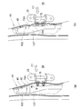
- FIG. 16A an impact load F3 is inputted to the left center pillar 15 from the outside 39 side. A part of the impact load F3 is transmitted to the front flange joint 47 and the rear flange joint 48 as a load F4. At the same time, the pillar outer 43, the pillar stiffener 42, and the stiffener reinforcing member 45 are deformed as indicated by the arrow A with the remaining load F5 of the impact load F3.
- the pillar outer 43, the pillar stiffener 42, and the stiffener reinforcing member 45 are deformed, so that the pillar stiffener 42 passes through the stiffener reinforcing member 45 and the inner reinforcing member 44 (cross section U-shaped portion 86). It hits the inner reinforcing outer wall 81. Therefore, the remaining load F5 is transmitted as the load F6 to the inner inner wall 51 through the stiffener reinforcing member 45 and the inner reinforcing member 44.
- the stiffener reinforcing outer wall 101 of the stiffener reinforcing member 45 is disposed so as to overlap the inner reinforcing outer wall 81 of the U-shaped section 86 in the vehicle width direction. Therefore, the stiffener reinforcing outer wall 101 is disposed at a position close to the inner reinforcing outer wall 81. Therefore, the remaining load F5 can be quickly transmitted to the inner reinforcing member 44 via the stiffener reinforcing member 45.
- the impact load F3 (see FIG. 16A) input to the left center pillar 15 can be quickly distributed to the front flange joint 47, the rear flange joint 48, and the inner inner wall 51. Thereby, the impact load F3 can be suitably absorbed by the left center pillar 15, and the impact absorption performance of the left center pillar 15 can be enhanced.
- the front ridge line 115 of the stiffener reinforcing member 45 is brought closer to the front ridge line 67 of the pillar stiffener 42, and the rear ridge line 116 of the stiffener reinforcing member 45 is brought closer to the rear ridge line 68 of the pillar stiffener 42. It has been. Therefore, as shown in FIG. 16B, when the pillar stiffener 42 is deformed by the remaining load F5, a part of the load F5 is transferred from the front edge line 67 and the rear edge line 68 of the pillar stiffener 42 to the stiffener reinforcing member 45. The front ridge line 115 and the rear ridge line 116 can be quickly transmitted. Accordingly, a part of the remaining load F5 can be quickly absorbed by the stiffener reinforcing member 45 (particularly, the front ridge line 115 and the rear ridge line 116).
- the inner reinforcing member 44 has a U-shaped cross-section 86 that bulges toward the vehicle exterior 39 side. Therefore, in a state where the pillar stiffener 42 is deformed and hits the inner reinforcing member 44, the rigidity and strength of the cross-sectional U-shaped portion 86 can be ensured with respect to the load F5 transmitted to the cross-sectional U-shaped portion 86. That is, the load F ⁇ b> 5 transmitted to the cross-section U-shaped portion 86 can be supported by the cross-sectional U-shaped portion 86. Thereby, it can suppress that the left center pillar 15 compresses and deforms to the compartment 38 side, and can suppress that the space of the compartment 38 decreases.
- the load F4 transmitted to the front flange joint 47 and the rear flange joint 48 can be kept small. Thereby, the strength against the impact load F3 is maintained at the front flange joint portion 47 and the rear flange joint portion 48 of the left center pillar 15, and the rigidity of the left center pillar 15 is ensured.
- the overhanging enlarged portions 107 of the stiffener reinforcing front wall 102 and the stiffener reinforcing rear wall 103 are substantially the same members.
- the overhanging enlarged portion 107 of the stiffener reinforcing front wall 102 will be described. Description of the overhanging enlarged portion 107 of the reinforced rear wall 103 is omitted.
- the impact load F7 is input to the upper door hinge 33 from the outside 39 side.
- the input impact load F7 is transmitted to the upper hinge mounting surface 72 of the pillar stiffener 42, and the upper continuous surface 74A of the pillar stiffener 42 is deformed by the transmitted impact load F7.
- the upper continuous surface 74A As the upper continuous surface 74A is deformed, the upper continuous surface 74A moves toward the stiffener reinforcing member 45 at an early stage as indicated by an arrow B.
- the upper continuous surface 74 ⁇ / b> A hits the stiffener reinforcement outer wall 101 of the stiffener reinforcement member 45.
- An overhanging enlarged portion 107 of the stiffener reinforcing front wall 102 is provided at a portion facing the upper continuous surface 74A. Therefore, when the upper continuous surface 74A hits the stiffener reinforcing outer wall 101, the impact load F7 is quickly transmitted to the overhanging enlarged portion 107 of the stiffener reinforcing member 45 through the upper continuous surface 74A.
- the overhanging enlarged portion 107 of the stiffener reinforcement front wall 102 is ensured to have higher rigidity and strength than the other parts of the stiffener reinforcement front wall 102. Thereby, the impact load F7 transmitted from the upper continuous surface 74A can be suitably supported by the overhanging enlarged portion 107.
- the vehicle body side structure according to the present invention is not limited to the above-described embodiments, and can be changed or improved as appropriate.
- the configuration in which the stiffener reinforcing member 45 is interposed between the inner reinforcing member 44 and the pillar stiffener 42 has been described.
- the present invention is not limited to this, and a configuration in which the stiffener reinforcing member 45 is not interposed is also possible. is there.
- the pillar stiffener 42 when an impact load is input to the left center pillar 15 from the vehicle exterior 39 side, the pillar stiffener 42 is deformed to the vehicle compartment 38 side and hits the inner reinforcing member 44. Therefore, the impact load input to the left center pillar 15 is transmitted to the inner front flange 54 and the inner rear flange 55, and is transmitted to the inner inner wall 51 through the inner reinforcing member 44. Thereby, the impact load input to the pillar stiffener 42 can be distributed to the inner front flange 54, the inner rear flange 55, and the inner inner wall 51, and can be suitably absorbed by the left center pillar 15, and the shock absorbing performance of the left center pillar 15 is enhanced. be able to.
- the inner reinforcing member 44 is bulged outward in the vehicle width direction. Therefore, the pillar stiffener 42 that is deformed toward the vehicle width center side by the impact load input from the outside in the vehicle width direction hits the inner reinforcement member 44 to transmit the load, so that the impact load can be supported by the inner reinforcement member 44. . Thereby, it is possible to suppress the left center pillar 15 from being compressed and deformed inward in the vehicle width direction, and it is possible to suppress the space of the vehicle compartment 38 from being reduced.
- the present invention is not limited to this.
- a concave portion can be used instead of the through hole 112. is there.
- the stiffness and strength of the stiffener reinforcing member 45 can be further increased.
- the vehicle body side structure left vehicle body side, left and right center pillars, rear side doors, upper and lower door hinges, pillar inner, pillar stiffener, inner reinforcing member, stiffener reinforcing member, pillar closed cross section, inner inner wall, Inner front wall, inner rear wall, inner front flange, inner rear flange, stiffener outer wall, inner reinforced outer wall, inner reinforced front wall, inner reinforced rear wall, inner reinforced front flange, inner reinforced flange, cross-section U-shaped, inner reinforced
- the shape and formation of the cross-section enlarged portion, stiffener reinforced outer wall, stiffener reinforced front wall, stiffener reinforced rear wall, overhang reduced portion, overhang enlarged portion, and through hole are not limited to those illustrated, but can be changed as appropriate. is there.
- the present invention is suitable for application to an automobile having a center pillar that extends in the vertical direction on the side of the vehicle body, and a vehicle body side structure having a pillar closed cross section in the center pillar.
- SYMBOLS 10 Car body side part structure, 11 ... Left car body side part (car body side part), 15, 16 ... Left and right center pillar (center pillar), 31 ... Rear side door (side door), 33, 34 ... Upper and lower door hinges (door hinges) ), 36 ... Bolt, 37 ... Nut, 41 ... Pillar inner, 42 ... Pillar stiffener, 44 ... Inner reinforcing member, 45 ... Stiffener reinforcing member, 49 ... Pillar closed section (closed section), 51 ... Inner inner wall, 51b ... Inner inner wall Front end portion (front end portion of the vehicle body), 51c ...
- inner reinforcing outer wall Rear end portion (end portion on the rear side of the vehicle body), 82 ... inner reinforcement front wall, 83 ... inner reinforcement rear wall, 84 ... inner reinforcement front flange, 85 ... inner reinforcement rear flange, 86 ... U-shaped section (section omitted) U-shaped part), 88 ... Inner reinforcing cross-section enlarged portion, 101 ... Stiffener reinforcing outer wall, 101d ... Stiffener reinforcing outer wall front end (front end of vehicle body), 101e ... Stiffener reinforcing outer wall rear end ( 102 ... Stiffener reinforcing front wall, 103 ... Stiffener reinforcing rear wall, 108 ...
- Overhang reducing portion 107 ... Overhang expanding portion, 112 ... Through hole, S1 ... Predetermined interval, S2 ... Predetermined interval Larger gap W3 ... projecting length of the projecting enlarged portion, W4 ... overhanging dimension of the overhang reduction unit.
Landscapes
- Engineering & Computer Science (AREA)
- Mechanical Engineering (AREA)
- Chemical & Material Sciences (AREA)
- Combustion & Propulsion (AREA)
- Transportation (AREA)
- Body Structure For Vehicles (AREA)
Abstract
Priority Applications (3)
| Application Number | Priority Date | Filing Date | Title |
|---|---|---|---|
| MX2016012384A MX2016012384A (es) | 2014-03-25 | 2015-03-23 | Estructura lateral de la carroceria de vehiculo. |
| CA2943630A CA2943630A1 (fr) | 2014-03-25 | 2015-03-23 | Structure laterale de caisse de vehicule |
| US15/127,954 US9868470B2 (en) | 2014-03-25 | 2015-03-23 | Vehicle body side structure |
Applications Claiming Priority (2)
| Application Number | Priority Date | Filing Date | Title |
|---|---|---|---|
| JP2014-061799 | 2014-03-25 | ||
| JP2014061799 | 2014-03-25 |
Publications (1)
| Publication Number | Publication Date |
|---|---|
| WO2015146902A1 true WO2015146902A1 (fr) | 2015-10-01 |
Family
ID=54195415
Family Applications (1)
| Application Number | Title | Priority Date | Filing Date |
|---|---|---|---|
| PCT/JP2015/058719 Ceased WO2015146902A1 (fr) | 2014-03-25 | 2015-03-23 | Structure latérale de caisse de véhicule |
Country Status (4)
| Country | Link |
|---|---|
| US (1) | US9868470B2 (fr) |
| CA (1) | CA2943630A1 (fr) |
| MX (1) | MX2016012384A (fr) |
| WO (1) | WO2015146902A1 (fr) |
Cited By (1)
| Publication number | Priority date | Publication date | Assignee | Title |
|---|---|---|---|---|
| CN108860323A (zh) * | 2018-08-13 | 2018-11-23 | 奇瑞汽车股份有限公司 | 车身b柱加强装置及车身b柱加强方法 |
Families Citing this family (11)
| Publication number | Priority date | Publication date | Assignee | Title |
|---|---|---|---|---|
| US10486750B2 (en) * | 2015-08-20 | 2019-11-26 | Nippon Steel Corporation | Steel sheet member combination structure, automotive structural member, center pillar, bumper, and door beam |
| US10099726B2 (en) * | 2016-11-22 | 2018-10-16 | Ford Global Technologies, Llc | Patch welded blank on an A-pillar |
| TWD188468S (zh) * | 2016-11-30 | 2018-02-11 | Bmw股份有限公司 | 汽車用尾門 |
| JP6684037B2 (ja) * | 2017-01-20 | 2020-04-22 | 本田技研工業株式会社 | 車体前部構造 |
| JP6555303B2 (ja) * | 2017-07-28 | 2019-08-07 | マツダ株式会社 | 車両の側部車体構造 |
| JP6954033B2 (ja) * | 2017-11-15 | 2021-10-27 | トヨタ自動車株式会社 | 車両のボディ骨格構造 |
| JP6713497B2 (ja) * | 2018-03-06 | 2020-06-24 | 株式会社豊田自動織機 | 車両用センタピラー |
| US10940808B2 (en) * | 2019-05-01 | 2021-03-09 | Nissan North America, Inc. | Trim panel member for a vehicle |
| DE102020117989B3 (de) | 2020-07-08 | 2021-09-16 | Bayerische Motoren Werke Aktiengesellschaft | Befestigungsanordnung eines Fangelements an einer Fahrzeugsäule einer Kraftwagenkarosserie sowie Kraftwagen |
| CN112278087A (zh) * | 2020-11-19 | 2021-01-29 | 柳州铁道职业技术学院 | 一种提升乘用车顶部抗压性能结构 |
| JP7392702B2 (ja) * | 2021-10-28 | 2023-12-06 | トヨタ自動車株式会社 | 車両側部構造 |
Citations (7)
| Publication number | Priority date | Publication date | Assignee | Title |
|---|---|---|---|---|
| JPH09267767A (ja) * | 1996-04-01 | 1997-10-14 | Suzuki Motor Corp | 自動車の車体構造 |
| JP2001310762A (ja) * | 2000-04-28 | 2001-11-06 | Fuji Heavy Ind Ltd | センタピラーの結合構造 |
| JP2007302029A (ja) * | 2006-05-09 | 2007-11-22 | Toyota Auto Body Co Ltd | 車両のピラー構造 |
| JP2007326376A (ja) * | 2006-06-06 | 2007-12-20 | Toyota Auto Body Co Ltd | 車両のピラー構造 |
| JP2012025174A (ja) * | 2010-07-20 | 2012-02-09 | Mazda Motor Corp | 車両の側部車体構造 |
| JP2012056407A (ja) * | 2010-09-07 | 2012-03-22 | Unipres Corp | 自動車用車体骨格における補強構造 |
| JP2013023038A (ja) * | 2011-07-19 | 2013-02-04 | Toyota Motor East Japan Inc | 車両用センターピラー |
Family Cites Families (3)
| Publication number | Priority date | Publication date | Assignee | Title |
|---|---|---|---|---|
| JPH0781615A (ja) | 1993-09-16 | 1995-03-28 | Nissan Motor Co Ltd | 自動車ピラーの下部構造 |
| JP5093931B2 (ja) * | 2009-04-10 | 2012-12-12 | 本田技研工業株式会社 | 車両の側部構造 |
| US8740290B2 (en) * | 2010-03-23 | 2014-06-03 | Honda Motor Co., Ltd. | Structure for side section of vehicle body |
-
2015
- 2015-03-23 WO PCT/JP2015/058719 patent/WO2015146902A1/fr not_active Ceased
- 2015-03-23 CA CA2943630A patent/CA2943630A1/fr not_active Abandoned
- 2015-03-23 MX MX2016012384A patent/MX2016012384A/es unknown
- 2015-03-23 US US15/127,954 patent/US9868470B2/en not_active Expired - Fee Related
Patent Citations (7)
| Publication number | Priority date | Publication date | Assignee | Title |
|---|---|---|---|---|
| JPH09267767A (ja) * | 1996-04-01 | 1997-10-14 | Suzuki Motor Corp | 自動車の車体構造 |
| JP2001310762A (ja) * | 2000-04-28 | 2001-11-06 | Fuji Heavy Ind Ltd | センタピラーの結合構造 |
| JP2007302029A (ja) * | 2006-05-09 | 2007-11-22 | Toyota Auto Body Co Ltd | 車両のピラー構造 |
| JP2007326376A (ja) * | 2006-06-06 | 2007-12-20 | Toyota Auto Body Co Ltd | 車両のピラー構造 |
| JP2012025174A (ja) * | 2010-07-20 | 2012-02-09 | Mazda Motor Corp | 車両の側部車体構造 |
| JP2012056407A (ja) * | 2010-09-07 | 2012-03-22 | Unipres Corp | 自動車用車体骨格における補強構造 |
| JP2013023038A (ja) * | 2011-07-19 | 2013-02-04 | Toyota Motor East Japan Inc | 車両用センターピラー |
Cited By (2)
| Publication number | Priority date | Publication date | Assignee | Title |
|---|---|---|---|---|
| CN108860323A (zh) * | 2018-08-13 | 2018-11-23 | 奇瑞汽车股份有限公司 | 车身b柱加强装置及车身b柱加强方法 |
| CN108860323B (zh) * | 2018-08-13 | 2021-04-27 | 奇瑞汽车股份有限公司 | 车身b柱加强装置及车身b柱加强方法 |
Also Published As
| Publication number | Publication date |
|---|---|
| US9868470B2 (en) | 2018-01-16 |
| US20170101133A1 (en) | 2017-04-13 |
| MX2016012384A (es) | 2017-05-23 |
| CA2943630A1 (fr) | 2015-10-01 |
Similar Documents
| Publication | Publication Date | Title |
|---|---|---|
| WO2015146902A1 (fr) | Structure latérale de caisse de véhicule | |
| US9688311B2 (en) | Vehicle body front portion structure | |
| WO2015146903A1 (fr) | Structure latérale de carrosserie de véhicule | |
| US6053564A (en) | Vehicle body side sill reinforcing bulkhead | |
| CN102470899B (zh) | 汽车的上部车身构造 | |
| EP2740650B1 (fr) | Structure arrière de carrosserie de véhicule | |
| JP5593813B2 (ja) | 車体補強構造 | |
| US8366184B2 (en) | Structure for vehicle body upper portion | |
| US10549787B2 (en) | Vehicle body floor structure | |
| KR102371245B1 (ko) | 차량의 센터 필러 구조 | |
| JP6235542B2 (ja) | 車体前部構造 | |
| JP6181099B2 (ja) | 車体の後部構造 | |
| CN104364142A (zh) | 在y轴上减弱和在z轴上加强的中柱隔板 | |
| JP2018199471A (ja) | 車体前部構造 | |
| US20180170440A1 (en) | Vehicle body front structure | |
| JP5093094B2 (ja) | ダッシュパネルとトンネル部との結合部構造 | |
| JP6237669B2 (ja) | 車両の上部車体構造 | |
| JP6016246B2 (ja) | 自動車の車体構造 | |
| JP6634068B2 (ja) | 車体前部構造 | |
| JP7152446B2 (ja) | フロントピラー下部構造 | |
| JP5088625B2 (ja) | 車両のピラー構造 | |
| JP7310615B2 (ja) | 車両の車体構造 | |
| JP6072729B2 (ja) | 車体構造 | |
| JP5818477B2 (ja) | 自動車の前部車体構造 | |
| JP2017210152A (ja) | 車体の接合構造 |
Legal Events
| Date | Code | Title | Description |
|---|---|---|---|
| 121 | Ep: the epo has been informed by wipo that ep was designated in this application |
Ref document number: 15768695 Country of ref document: EP Kind code of ref document: A1 |
|
| WWE | Wipo information: entry into national phase |
Ref document number: 15127954 Country of ref document: US |
|
| ENP | Entry into the national phase |
Ref document number: 2943630 Country of ref document: CA |
|
| WWE | Wipo information: entry into national phase |
Ref document number: MX/A/2016/012384 Country of ref document: MX |
|
| NENP | Non-entry into the national phase |
Ref country code: DE |
|
| 122 | Ep: pct application non-entry in european phase |
Ref document number: 15768695 Country of ref document: EP Kind code of ref document: A1 |
|
| NENP | Non-entry into the national phase |
Ref country code: JP |