WO2015159698A1 - 排ガス浄化システム、触媒、及び排ガス浄化方法 - Google Patents
排ガス浄化システム、触媒、及び排ガス浄化方法 Download PDFInfo
- Publication number
- WO2015159698A1 WO2015159698A1 PCT/JP2015/059969 JP2015059969W WO2015159698A1 WO 2015159698 A1 WO2015159698 A1 WO 2015159698A1 JP 2015059969 W JP2015059969 W JP 2015059969W WO 2015159698 A1 WO2015159698 A1 WO 2015159698A1
- Authority
- WO
- WIPO (PCT)
- Prior art keywords
- exhaust gas
- catalyst
- metal
- concentration
- gas purification
- Prior art date
- Legal status (The legal status is an assumption and is not a legal conclusion. Google has not performed a legal analysis and makes no representation as to the accuracy of the status listed.)
- Ceased
Links
Images


Classifications
-
- B—PERFORMING OPERATIONS; TRANSPORTING
- B01—PHYSICAL OR CHEMICAL PROCESSES OR APPARATUS IN GENERAL
- B01D—SEPARATION
- B01D53/00—Separation of gases or vapours; Recovering vapours of volatile solvents from gases; Chemical or biological purification of waste gases, e.g. engine exhaust gases, smoke, fumes, flue gases, aerosols
- B01D53/34—Chemical or biological purification of waste gases
- B01D53/92—Chemical or biological purification of waste gases of engine exhaust gases
- B01D53/94—Chemical or biological purification of waste gases of engine exhaust gases by catalytic processes
- B01D53/9404—Removing only nitrogen compounds
- B01D53/9409—Nitrogen oxides
- B01D53/9413—Processes characterised by a specific catalyst
- B01D53/9418—Processes characterised by a specific catalyst for removing nitrogen oxides by selective catalytic reduction [SCR] using a reducing agent in a lean exhaust gas
-
- B—PERFORMING OPERATIONS; TRANSPORTING
- B01—PHYSICAL OR CHEMICAL PROCESSES OR APPARATUS IN GENERAL
- B01D—SEPARATION
- B01D53/00—Separation of gases or vapours; Recovering vapours of volatile solvents from gases; Chemical or biological purification of waste gases, e.g. engine exhaust gases, smoke, fumes, flue gases, aerosols
- B01D53/34—Chemical or biological purification of waste gases
- B01D53/92—Chemical or biological purification of waste gases of engine exhaust gases
- B01D53/94—Chemical or biological purification of waste gases of engine exhaust gases by catalytic processes
- B01D53/9445—Simultaneously removing carbon monoxide, hydrocarbons or nitrogen oxides making use of three-way catalysts [TWC] or four-way-catalysts [FWC]
-
- B—PERFORMING OPERATIONS; TRANSPORTING
- B01—PHYSICAL OR CHEMICAL PROCESSES OR APPARATUS IN GENERAL
- B01J—CHEMICAL OR PHYSICAL PROCESSES, e.g. CATALYSIS OR COLLOID CHEMISTRY; THEIR RELEVANT APPARATUS
- B01J23/00—Catalysts comprising metals or metal oxides or hydroxides, not provided for in group B01J21/00
- B01J23/70—Catalysts comprising metals or metal oxides or hydroxides, not provided for in group B01J21/00 of the iron group metals or copper
- B01J23/74—Iron group metals
- B01J23/755—Nickel
-
- B—PERFORMING OPERATIONS; TRANSPORTING
- B01—PHYSICAL OR CHEMICAL PROCESSES OR APPARATUS IN GENERAL
- B01J—CHEMICAL OR PHYSICAL PROCESSES, e.g. CATALYSIS OR COLLOID CHEMISTRY; THEIR RELEVANT APPARATUS
- B01J23/00—Catalysts comprising metals or metal oxides or hydroxides, not provided for in group B01J21/00
- B01J23/70—Catalysts comprising metals or metal oxides or hydroxides, not provided for in group B01J21/00 of the iron group metals or copper
- B01J23/89—Catalysts comprising metals or metal oxides or hydroxides, not provided for in group B01J21/00 of the iron group metals or copper combined with noble metals
- B01J23/892—Nickel and noble metals
-
- B—PERFORMING OPERATIONS; TRANSPORTING
- B01—PHYSICAL OR CHEMICAL PROCESSES OR APPARATUS IN GENERAL
- B01J—CHEMICAL OR PHYSICAL PROCESSES, e.g. CATALYSIS OR COLLOID CHEMISTRY; THEIR RELEVANT APPARATUS
- B01J23/00—Catalysts comprising metals or metal oxides or hydroxides, not provided for in group B01J21/00
- B01J23/70—Catalysts comprising metals or metal oxides or hydroxides, not provided for in group B01J21/00 of the iron group metals or copper
- B01J23/89—Catalysts comprising metals or metal oxides or hydroxides, not provided for in group B01J21/00 of the iron group metals or copper combined with noble metals
- B01J23/8933—Catalysts comprising metals or metal oxides or hydroxides, not provided for in group B01J21/00 of the iron group metals or copper combined with noble metals also combined with metals, or metal oxides or hydroxides provided for in groups B01J23/02 - B01J23/36
- B01J23/8993—Catalysts comprising metals or metal oxides or hydroxides, not provided for in group B01J21/00 of the iron group metals or copper combined with noble metals also combined with metals, or metal oxides or hydroxides provided for in groups B01J23/02 - B01J23/36 with chromium, molybdenum or tungsten
-
- B—PERFORMING OPERATIONS; TRANSPORTING
- B01—PHYSICAL OR CHEMICAL PROCESSES OR APPARATUS IN GENERAL
- B01J—CHEMICAL OR PHYSICAL PROCESSES, e.g. CATALYSIS OR COLLOID CHEMISTRY; THEIR RELEVANT APPARATUS
- B01J37/00—Processes, in general, for preparing catalysts; Processes, in general, for activation of catalysts
- B01J37/02—Impregnation, coating or precipitation
- B01J37/0215—Coating
- B01J37/0225—Coating of metal substrates
-
- F—MECHANICAL ENGINEERING; LIGHTING; HEATING; WEAPONS; BLASTING
- F01—MACHINES OR ENGINES IN GENERAL; ENGINE PLANTS IN GENERAL; STEAM ENGINES
- F01N—GAS-FLOW SILENCERS OR EXHAUST APPARATUS FOR MACHINES OR ENGINES IN GENERAL; GAS-FLOW SILENCERS OR EXHAUST APPARATUS FOR INTERNAL-COMBUSTION ENGINES
- F01N13/00—Exhaust or silencing apparatus characterised by constructional features
- F01N13/009—Exhaust or silencing apparatus characterised by constructional features having two or more separate purifying devices arranged in series
-
- F—MECHANICAL ENGINEERING; LIGHTING; HEATING; WEAPONS; BLASTING
- F01—MACHINES OR ENGINES IN GENERAL; ENGINE PLANTS IN GENERAL; STEAM ENGINES
- F01N—GAS-FLOW SILENCERS OR EXHAUST APPARATUS FOR MACHINES OR ENGINES IN GENERAL; GAS-FLOW SILENCERS OR EXHAUST APPARATUS FOR INTERNAL-COMBUSTION ENGINES
- F01N3/00—Exhaust or silencing apparatus having means for purifying, rendering innocuous, or otherwise treating exhaust
- F01N3/08—Exhaust or silencing apparatus having means for purifying, rendering innocuous, or otherwise treating exhaust for rendering innocuous
- F01N3/10—Exhaust or silencing apparatus having means for purifying, rendering innocuous, or otherwise treating exhaust for rendering innocuous by thermal or catalytic conversion of noxious components of exhaust
- F01N3/101—Three-way catalysts
-
- F—MECHANICAL ENGINEERING; LIGHTING; HEATING; WEAPONS; BLASTING
- F01—MACHINES OR ENGINES IN GENERAL; ENGINE PLANTS IN GENERAL; STEAM ENGINES
- F01N—GAS-FLOW SILENCERS OR EXHAUST APPARATUS FOR MACHINES OR ENGINES IN GENERAL; GAS-FLOW SILENCERS OR EXHAUST APPARATUS FOR INTERNAL-COMBUSTION ENGINES
- F01N3/00—Exhaust or silencing apparatus having means for purifying, rendering innocuous, or otherwise treating exhaust
- F01N3/08—Exhaust or silencing apparatus having means for purifying, rendering innocuous, or otherwise treating exhaust for rendering innocuous
- F01N3/10—Exhaust or silencing apparatus having means for purifying, rendering innocuous, or otherwise treating exhaust for rendering innocuous by thermal or catalytic conversion of noxious components of exhaust
- F01N3/18—Exhaust or silencing apparatus having means for purifying, rendering innocuous, or otherwise treating exhaust for rendering innocuous by thermal or catalytic conversion of noxious components of exhaust characterised by methods of operation; Control
- F01N3/20—Exhaust or silencing apparatus having means for purifying, rendering innocuous, or otherwise treating exhaust for rendering innocuous by thermal or catalytic conversion of noxious components of exhaust characterised by methods of operation; Control specially adapted for catalytic conversion
-
- F—MECHANICAL ENGINEERING; LIGHTING; HEATING; WEAPONS; BLASTING
- F01—MACHINES OR ENGINES IN GENERAL; ENGINE PLANTS IN GENERAL; STEAM ENGINES
- F01N—GAS-FLOW SILENCERS OR EXHAUST APPARATUS FOR MACHINES OR ENGINES IN GENERAL; GAS-FLOW SILENCERS OR EXHAUST APPARATUS FOR INTERNAL-COMBUSTION ENGINES
- F01N9/00—Electrical control of exhaust gas treating apparatus
-
- B—PERFORMING OPERATIONS; TRANSPORTING
- B01—PHYSICAL OR CHEMICAL PROCESSES OR APPARATUS IN GENERAL
- B01D—SEPARATION
- B01D2251/00—Reactants
- B01D2251/20—Reductants
- B01D2251/202—Hydrogen
-
- B—PERFORMING OPERATIONS; TRANSPORTING
- B01—PHYSICAL OR CHEMICAL PROCESSES OR APPARATUS IN GENERAL
- B01D—SEPARATION
- B01D2255/00—Catalysts
- B01D2255/20—Metals or compounds thereof
- B01D2255/207—Transition metals
-
- B—PERFORMING OPERATIONS; TRANSPORTING
- B01—PHYSICAL OR CHEMICAL PROCESSES OR APPARATUS IN GENERAL
- B01D—SEPARATION
- B01D2255/00—Catalysts
- B01D2255/20—Metals or compounds thereof
- B01D2255/207—Transition metals
- B01D2255/20738—Iron
-
- B—PERFORMING OPERATIONS; TRANSPORTING
- B01—PHYSICAL OR CHEMICAL PROCESSES OR APPARATUS IN GENERAL
- B01D—SEPARATION
- B01D2255/00—Catalysts
- B01D2255/20—Metals or compounds thereof
- B01D2255/207—Transition metals
- B01D2255/20753—Nickel
-
- B—PERFORMING OPERATIONS; TRANSPORTING
- B01—PHYSICAL OR CHEMICAL PROCESSES OR APPARATUS IN GENERAL
- B01D—SEPARATION
- B01D2255/00—Catalysts
- B01D2255/90—Physical characteristics of catalysts
- B01D2255/92—Dimensions
- B01D2255/9205—Porosity
-
- B—PERFORMING OPERATIONS; TRANSPORTING
- B01—PHYSICAL OR CHEMICAL PROCESSES OR APPARATUS IN GENERAL
- B01D—SEPARATION
- B01D53/00—Separation of gases or vapours; Recovering vapours of volatile solvents from gases; Chemical or biological purification of waste gases, e.g. engine exhaust gases, smoke, fumes, flue gases, aerosols
- B01D53/34—Chemical or biological purification of waste gases
- B01D53/92—Chemical or biological purification of waste gases of engine exhaust gases
- B01D53/94—Chemical or biological purification of waste gases of engine exhaust gases by catalytic processes
- B01D53/9459—Removing one or more of nitrogen oxides, carbon monoxide, or hydrocarbons by multiple successive catalytic functions; systems with more than one different function, e.g. zone coated catalysts
- B01D53/9477—Removing one or more of nitrogen oxides, carbon monoxide, or hydrocarbons by multiple successive catalytic functions; systems with more than one different function, e.g. zone coated catalysts with catalysts positioned on separate bricks, e.g. exhaust systems
-
- B—PERFORMING OPERATIONS; TRANSPORTING
- B01—PHYSICAL OR CHEMICAL PROCESSES OR APPARATUS IN GENERAL
- B01J—CHEMICAL OR PHYSICAL PROCESSES, e.g. CATALYSIS OR COLLOID CHEMISTRY; THEIR RELEVANT APPARATUS
- B01J35/00—Catalysts, in general, characterised by their form or physical properties
- B01J35/50—Catalysts, in general, characterised by their form or physical properties characterised by their shape or configuration
- B01J35/56—Foraminous structures having flow-through passages or channels, e.g. grids or three-dimensional [3D] monoliths
-
- F—MECHANICAL ENGINEERING; LIGHTING; HEATING; WEAPONS; BLASTING
- F01—MACHINES OR ENGINES IN GENERAL; ENGINE PLANTS IN GENERAL; STEAM ENGINES
- F01N—GAS-FLOW SILENCERS OR EXHAUST APPARATUS FOR MACHINES OR ENGINES IN GENERAL; GAS-FLOW SILENCERS OR EXHAUST APPARATUS FOR INTERNAL-COMBUSTION ENGINES
- F01N2240/00—Combination or association of two or more different exhaust treating devices, or of at least one such device with an auxiliary device, not covered by indexing codes F01N2230/00 or F01N2250/00, one of the devices being
- F01N2240/30—Combination or association of two or more different exhaust treating devices, or of at least one such device with an auxiliary device, not covered by indexing codes F01N2230/00 or F01N2250/00, one of the devices being a fuel reformer
-
- F—MECHANICAL ENGINEERING; LIGHTING; HEATING; WEAPONS; BLASTING
- F01—MACHINES OR ENGINES IN GENERAL; ENGINE PLANTS IN GENERAL; STEAM ENGINES
- F01N—GAS-FLOW SILENCERS OR EXHAUST APPARATUS FOR MACHINES OR ENGINES IN GENERAL; GAS-FLOW SILENCERS OR EXHAUST APPARATUS FOR INTERNAL-COMBUSTION ENGINES
- F01N2330/00—Structure of catalyst support or particle filter
- F01N2330/22—Metal foam
-
- F—MECHANICAL ENGINEERING; LIGHTING; HEATING; WEAPONS; BLASTING
- F01—MACHINES OR ENGINES IN GENERAL; ENGINE PLANTS IN GENERAL; STEAM ENGINES
- F01N—GAS-FLOW SILENCERS OR EXHAUST APPARATUS FOR MACHINES OR ENGINES IN GENERAL; GAS-FLOW SILENCERS OR EXHAUST APPARATUS FOR INTERNAL-COMBUSTION ENGINES
- F01N2370/00—Selection of materials for exhaust purification
- F01N2370/02—Selection of materials for exhaust purification used in catalytic reactors
-
- F—MECHANICAL ENGINEERING; LIGHTING; HEATING; WEAPONS; BLASTING
- F01—MACHINES OR ENGINES IN GENERAL; ENGINE PLANTS IN GENERAL; STEAM ENGINES
- F01N—GAS-FLOW SILENCERS OR EXHAUST APPARATUS FOR MACHINES OR ENGINES IN GENERAL; GAS-FLOW SILENCERS OR EXHAUST APPARATUS FOR INTERNAL-COMBUSTION ENGINES
- F01N2570/00—Exhaust treating apparatus eliminating, absorbing or adsorbing specific elements or compounds
- F01N2570/14—Nitrogen oxides
-
- F—MECHANICAL ENGINEERING; LIGHTING; HEATING; WEAPONS; BLASTING
- F01—MACHINES OR ENGINES IN GENERAL; ENGINE PLANTS IN GENERAL; STEAM ENGINES
- F01N—GAS-FLOW SILENCERS OR EXHAUST APPARATUS FOR MACHINES OR ENGINES IN GENERAL; GAS-FLOW SILENCERS OR EXHAUST APPARATUS FOR INTERNAL-COMBUSTION ENGINES
- F01N2900/00—Details of electrical control or of the monitoring of the exhaust gas treating apparatus
- F01N2900/06—Parameters used for exhaust control or diagnosing
- F01N2900/14—Parameters used for exhaust control or diagnosing said parameters being related to the exhaust gas
- F01N2900/1402—Exhaust gas composition
-
- F—MECHANICAL ENGINEERING; LIGHTING; HEATING; WEAPONS; BLASTING
- F01—MACHINES OR ENGINES IN GENERAL; ENGINE PLANTS IN GENERAL; STEAM ENGINES
- F01N—GAS-FLOW SILENCERS OR EXHAUST APPARATUS FOR MACHINES OR ENGINES IN GENERAL; GAS-FLOW SILENCERS OR EXHAUST APPARATUS FOR INTERNAL-COMBUSTION ENGINES
- F01N2900/00—Details of electrical control or of the monitoring of the exhaust gas treating apparatus
- F01N2900/06—Parameters used for exhaust control or diagnosing
- F01N2900/14—Parameters used for exhaust control or diagnosing said parameters being related to the exhaust gas
- F01N2900/1404—Exhaust gas temperature
-
- Y—GENERAL TAGGING OF NEW TECHNOLOGICAL DEVELOPMENTS; GENERAL TAGGING OF CROSS-SECTIONAL TECHNOLOGIES SPANNING OVER SEVERAL SECTIONS OF THE IPC; TECHNICAL SUBJECTS COVERED BY FORMER USPC CROSS-REFERENCE ART COLLECTIONS [XRACs] AND DIGESTS
- Y02—TECHNOLOGIES OR APPLICATIONS FOR MITIGATION OR ADAPTATION AGAINST CLIMATE CHANGE
- Y02A—TECHNOLOGIES FOR ADAPTATION TO CLIMATE CHANGE
- Y02A50/00—TECHNOLOGIES FOR ADAPTATION TO CLIMATE CHANGE in human health protection, e.g. against extreme weather
- Y02A50/20—Air quality improvement or preservation, e.g. vehicle emission control or emission reduction by using catalytic converters
-
- Y—GENERAL TAGGING OF NEW TECHNOLOGICAL DEVELOPMENTS; GENERAL TAGGING OF CROSS-SECTIONAL TECHNOLOGIES SPANNING OVER SEVERAL SECTIONS OF THE IPC; TECHNICAL SUBJECTS COVERED BY FORMER USPC CROSS-REFERENCE ART COLLECTIONS [XRACs] AND DIGESTS
- Y02—TECHNOLOGIES OR APPLICATIONS FOR MITIGATION OR ADAPTATION AGAINST CLIMATE CHANGE
- Y02T—CLIMATE CHANGE MITIGATION TECHNOLOGIES RELATED TO TRANSPORTATION
- Y02T10/00—Road transport of goods or passengers
- Y02T10/10—Internal combustion engine [ICE] based vehicles
- Y02T10/12—Improving ICE efficiencies
-
- Y—GENERAL TAGGING OF NEW TECHNOLOGICAL DEVELOPMENTS; GENERAL TAGGING OF CROSS-SECTIONAL TECHNOLOGIES SPANNING OVER SEVERAL SECTIONS OF THE IPC; TECHNICAL SUBJECTS COVERED BY FORMER USPC CROSS-REFERENCE ART COLLECTIONS [XRACs] AND DIGESTS
- Y02—TECHNOLOGIES OR APPLICATIONS FOR MITIGATION OR ADAPTATION AGAINST CLIMATE CHANGE
- Y02T—CLIMATE CHANGE MITIGATION TECHNOLOGIES RELATED TO TRANSPORTATION
- Y02T10/00—Road transport of goods or passengers
- Y02T10/10—Internal combustion engine [ICE] based vehicles
- Y02T10/40—Engine management systems
Definitions
- the present invention relates to an exhaust gas purification system, a catalyst, and an exhaust gas purification method for purifying exhaust gas discharged from a heat engine.
- exhaust gas purification such as catalysts in the exhaust gas passages
- An exhaust gas purification system for purifying exhaust gas by providing an apparatus is known.
- automobile engines that burn petroleum-based fuels such as gasoline and light oil mainly contain carbon monoxide (CO), hydrocarbons (HC), and nitrogen oxides (NOx) as harmful substances in the exhaust gas. It is.
- a heat-resistant oxide mainly composed of silica (SiO 2 ), alumina (Al 2 O 3 ), and ceria (CeO 2 ) is used as a carrier in the exhaust gas passage of the engine, and platinum is formed on the surface of the carrier.
- a three-way catalyst supporting a noble metal composed of a white metal element such as (Pt), palladium (Pd), rhodium (Rh) is provided. The three-way catalyst purifies exhaust gas by oxidizing or reducing each harmful substance to a harmless substance such as water (H 2 O), carbon dioxide (CO 2 ), or nitrogen (N 2 ).
- NOx is occluded by supporting an alkaline substance (barium (Ba), potassium (K), etc.) that occludes NOx, and thereafter the combustion injection amount is temporarily increased.
- a so-called SCR (Selective Catalytic Reduction) catalyst or the like is provided in the exhaust gas passage (see Patent Document 1).
- the noble metal used for the catalyst is dispersed and supported on the support in the form of particles.
- the temperature becomes too high the noble metal aggregates and the surface area is reduced, resulting in a problem that the exhaust gas purification performance is lowered.
- the present invention has been made to solve such a problem, and the object of the present invention is to purify exhaust gas without supporting a noble metal, and to maintain exhaust gas purification performance even in a high temperature state.
- An object is to provide an exhaust gas purification system, a catalyst, and an exhaust gas purification method.
- an exhaust gas purification system comprises a heat engine that exhausts exhaust gas, a transition metal element excluding a white metal element, and a metal having a porosity of 80% or more. And a catalyst for reducing NOx by contacting with exhaust gas having a reducing gas concentration of a predetermined concentration or more and 230 ° C. or more.
- the catalyst according to the invention is made of a transition metal element excluding a white metal element and made of a metal having a porosity of 80% or more. To do.
- the exhaust gas purification method according to the present invention comprises a transition metal element excluding a white metal element and a porosity of 80 in an exhaust gas passage of a heat engine in which a reducing gas concentration is a predetermined concentration or more and an exhaust gas having a temperature of 400 ° C. or more flows.
- a catalyst composed of at least% metal is provided, and NOx in the exhaust gas is reduced by bringing the catalyst into contact with an exhaust gas having a hydrogen concentration of the predetermined concentration or more and 230 ° C. or more.
- the exhaust gas can be purified without carrying a noble metal, and the exhaust gas purification performance can be maintained even in a high temperature state.
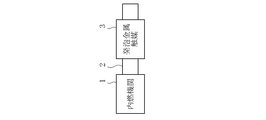
- FIG. 1 is a schematic configuration diagram of a first embodiment in which an exhaust gas purification system of the present invention is applied to an exhaust gas passage of an internal combustion engine. It is a schematic block diagram of 2nd Embodiment which applied the exhaust gas purification system of this invention to the exhaust gas channel
- FIG. 1A shows a schematic configuration diagram of a first embodiment in which the exhaust gas purification system of the present invention is applied to an exhaust gas passage of an internal combustion engine
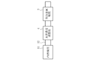
- FIG. 1B shows a second embodiment
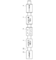
- FIG. 1C shows a schematic configuration diagram of the third embodiment. Has been.
- the exhaust gas purification system of the first embodiment is applied to an automobile, and as shown in FIG. 1A, a foam metal catalyst 3 is provided in an exhaust gas passage 2 of an internal combustion engine 1 (heat engine).
- the internal combustion engine 1 is, for example, a gasoline engine. That is, gasoline is burned with fuel, and exhaust gas mainly contains harmful substances such as carbon monoxide (CO), hydrocarbons (HC), and nitrogen oxides (NOx).
- the exhaust gas contains hydrogen (H 2 ) having a hydrogen concentration of at least 1.5% as a reducing gas, preferably 2 to 6%, and the exhaust gas temperature is at least at least 1.5%.
- the operating state is 400 ° C. or higher, preferably 600 ° C. or higher.
- the reducing gas is not limited to hydrogen, and may be, for example, carbon monoxide (CO) and hydrocarbons (HC) such as methane (CH 4 ), propane (C 3 H 8 ), butane (C 4 H 10 ). .
- the foam metal catalyst 3 is made of, for example, an open cell foam metal made of nickel (Ni) or a nickel alloy. That is, the foam metal does not carry noble metals such as platinum (Pt), palladium (Pd), and rhodium (Rh).
- nickel (Ni) is preferable because it exhibits sufficient exhaust gas purification performance from a relatively low temperature (400 ° C.), but is not limited thereto.
- the material of the foam metal catalyst 3 may be a transition metal element excluding a white metal element.
- the main component is nickel cobalt alloy (NiCo) or iron (Fe).
- Stainless steel (SUS) containing chromium (Cr) or the like, or iron (Fe) alone is desirable.
- the metal foam catalyst 3 requires a sufficient specific surface area, and preferably has a porosity of at least 80% or more, particularly 97% or more.
- the metal foam catalyst 3 using a metal foam is used as the catalyst.
- any catalyst made of a metal having a porosity of 80% or more may be used.
- stacked the metal made into the mesh shape, and the catalyst which consists of a porous metal body may be sufficient.
- dimples may be formed on the metal surface by plasma treatment or the like, or a metal catalyst formed into nanoparticles may be applied to the catalyst surface.
- the foamed metal catalyst 3 having such a structure has NOx, monoxide, because the reducing gas concentration in the exhaust gas is a predetermined concentration (for example, hydrogen 1.5%) or more and the exhaust gas temperature is in an atmosphere of 230 ° C. or more. Demonstrates the reduction function of carbon (CO) and hydrocarbon (HC).
- the metal foam catalyst 3 is provided in the exhaust gas passage 2 through which the exhaust gas having a hydrogen concentration of 2% or more and an exhaust gas temperature of 400 ° C. or more flows.
- the exhaust gas contacts the foam metal catalyst 3 and is harmless. It is reduced to a substance and the exhaust gas is purified.
- the exhaust gas purification system of the second embodiment is applied to an automobile in which a hydrogen concentration adjusting unit 4 is provided in the exhaust gas passage 12 of the internal combustion engine 11 in addition to the foam metal catalyst 3 as shown in FIG. 1B.
- the metal foam catalyst 3 has the same configuration as that of the first embodiment, and a detailed description thereof is omitted.
- the internal combustion engine 11 in the second embodiment does not have an operation state in which the hydrogen concentration in the exhaust gas is equal to or higher than a predetermined concentration (1.5%), and instead, the hydrogen concentration adjusting unit 4 (hydrogen concentration adjusting means).
- the hydrogen concentration in the exhaust gas can be adjusted to a predetermined concentration (1.5%) or more, preferably 2 to 6%.
- the hydrogen concentration adjusting unit 4 is provided between the internal combustion engine 11 and the metal foam catalyst 3 in the exhaust gas passage 12.
- the hydrogen concentration adjusting unit 4 is, for example, a reformer that reforms hydrocarbon (HC) into hydrogen (H 2 ) and carbon (C).
- a hydrogen storage device that stores hydrogen (H 2 ) at a relatively low temperature and discharges the stored hydrogen (H 2 ) at a high temperature may be used.
- it may be a so-called electrochemical reactor that becomes an electrolysis device that hydrogenates hydrocarbons when electricity is supplied from the outside.
- the exhaust gas discharged from the internal combustion engine 11 flows into the hydrogen concentration adjusting unit 4, and the hydrogen concentration is adjusted to a predetermined concentration (2%) by the hydrogen concentration adjusting unit 4. It is adjusted above. And the exhaust gas after adjustment which is 400 degreeC or more is sent to the foam metal catalyst 3, The NOx in exhaust gas is reduce
- the turbocharger 5 and the three-way catalyst 6 are provided in the exhaust gas passage 22 of the internal combustion engine 21. It is applied to automobiles equipped with. Since the metal foam catalyst 3 has the same configuration as that of the first embodiment and the hydrogen concentration adjusting unit 4 has the same configuration as that of the second embodiment, detailed description thereof will be omitted.
- the internal combustion engine 21 performs combustion by sucking in air that has been compressed by a compressor (not shown) of the turbocharger 5 and has reached a high temperature. Accordingly, since the exhaust gas also becomes high temperature, the internal combustion engine 21 has an operation state in which the fuel is periodically enriched to reduce the exhaust gas temperature in order to protect the turbocharger 5 and the like.
- the turbocharger 5 has a turbine disposed downstream of the exhaust gas passage 22 from the hydrogen concentration adjusting unit 4 and rotates the coaxial compressor by rotating the turbine by the exhaust gas flow. Compress the intake air.
- the foam metal catalyst 3 is provided in the exhaust gas passage 22 on the exhaust gas downstream side of the turbine of the turbocharger 5, and the three-way catalyst 6 is provided on the exhaust gas downstream side of the foam metal catalyst 3.
- the three-way catalyst 6 purifies harmful substances that could not be purified by the metal foam catalyst 3.
- the three-way catalyst 6 may be provided downstream of the exhaust metal catalyst 3 of the first embodiment and the second embodiment.
- the foam metal catalyst 3 should just be provided in the exhaust gas upstream side from the three-way catalyst 6, for example, may be provided in the exhaust gas upstream side from the turbine.
- the internal combustion engine 21 inhales and burns air that has been compressed and heated by the compressor of the turbocharger 5 and exhausts exhaust gas at 400 ° C. or higher.
- the hot exhaust gas flows into the hydrogen concentration adjusting unit 4, and the hydrogen concentration is adjusted to a predetermined concentration (2%) or more by the hydrogen concentration adjusting unit 4.
- the hydrogen concentration adjusting unit 4 can satisfactorily adjust the hydrogen concentration to a predetermined concentration or more.
- the exhaust gas after adjustment which is 400 ° C. or higher, is sent to the foam metal catalyst 3 after rotating the turbine of the turbocharger 5, so that the NOx in the exhaust gas is harmless by the foam metal catalyst 3. It is reduced and purified. Thereafter, the exhaust gas is further purified by flowing through the three-way catalyst 6.
- test specifications based on the configuration of the first embodiment, a test air-cooled four-cycle single-cylinder gasoline engine is used as the internal combustion engine, and nickel (Ni) alone is used as the foam metal catalyst, and the porosity is 97%. I used one.
- the ratio of exhaust gas components at the inlet and outlet of the metal foam catalyst 3 was measured three times at a predetermined time when the internal combustion engine was operated at 3500 rpm.
- the results are shown in Table 1 below.
- the exhaust gas temperature in each measurement is approximately 800 ° C. at the inlet portion of the foam metal catalyst and approximately 650 ° C. at the outlet portion.
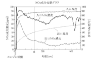
- FIG. 2 is a graph showing fluctuations in the NOx component in the exhaust gas before and after the metal foam catalyst
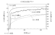
- FIG. 3 is a graph showing fluctuations in the CO component in the exhaust gas
- FIG. 4 is an exhaust gas corresponding to the elapsed time. The graph which shows the increase / decrease rate of each component in each is shown.
- the internal combustion engine used in this test contained 2 to 4% hydrogen (H 2 ) in the exhaust gas, and thus the hydrogen concentration was a predetermined concentration (2%) or more, and the exhaust gas It can be seen that NOx is reduced by approximately 80 to 90% by passing through the metal foam catalyst at a temperature of 400 ° C. or higher. Table 1 also shows that CO is reduced by about 30 to 40%.
- the temperature at the inlet of the metal foam catalyst immediately increases immediately after the engine is started, and the temperature at the outlet of the metal foam catalyst (outlet temperature) also increases accordingly.
- the NOx component concentration is reduced by about 20 to 30 ppm from the inlet NOx concentration immediately after the engine is started, and the amount of reduction is increased as the inlet temperature and the outlet temperature rise. From the vicinity of time t1 when the outlet temperature reaches 400 ° C., the outlet NOx concentration is stably reduced to 20 ppm or less, and even when the inlet NOx concentration fluctuates greatly, the outlet NOx concentration is suppressed to 20 ppm or less. I understand that.
- the CO component concentration is about 8 to 10% at the inlet portion of the foamed metal catalyst but is reduced to 5 to 7% at the outlet portion.
- CO is reduced at a rate of 0% to ⁇ 40%
- H 2 is also reduced at a rate of 0% to ⁇ 40%.
- NOx is significantly reduced at a rate of -70% to -95%.
- the foamed metal catalyst has a hydrogen concentration of 2% or more, and when the exhaust gas temperature is in an atmosphere of 400 ° C. or more, it has a significant effect. It exhibits NOx reduction performance and CO reduction performance, and realizes good exhaust gas purification performance.
- Table 2 shows the results of measuring the ratio of the exhaust gas component at the inlet and outlet when the stainless steel foam metal catalyst is used three times. .
- the exhaust gas temperature in each measurement is approximately 850 ° C. at the inlet portion of the foam metal catalyst and approximately 660 ° C. at the outlet portion.
- the foam metal catalyst 3 is composed of only a foam metal made of a transition metal element excluding the white metal element such as nickel (Ni), stainless steel (SUS), iron (Fe), etc. Compared to a catalyst using a noble metal consisting of, the cost can be greatly reduced.
- the catalyst since the catalyst is made of only the foam metal, the surface of the noble metal supported on the carrier aggregates due to high temperature and the surface area may decrease as in the case of the conventional catalyst. As shown in the graph of FIG. 4, the exhaust gas purification performance can be maintained for a long time.
- the reason why the exhaust gas purification performance is maintained for a long time is considered to be that the oxide film on the surface of the metal foam catalyst is removed by supplying hydrogen as a reducing gas.
- nickel (Ni) component of the metal foam catalyst 3 decomposes NOx to generate nickel oxide (NiO) and nitrogen (N 2 ) (2NO + 2Ni ⁇ N 2 + 2NiO).
- the oxide film is removed by hydrogen (H 2 ) as a reducing gas and returns to nickel (Ni) (2NiO + 2H 2 ⁇ 2Ni + 2H 2 O).
- Such a reaction requires an occlusion material that temporarily occludes NOx, and differs in configuration and purification process from an NOx occlusion catalyst that requires two processes of occlusion and reduction. It also requires a system that manages urea tanks and urea water, and has a different configuration and purification process from an SCR catalyst that reduces NOx by a direct chemical reaction with ammonia (NH 3 ) added to the exhaust instead of the catalyst metal. ing. That is, the exhaust gas purification system according to the present embodiment can purify NOx and maintain the exhaust gas purification performance while being simpler in structure than the conventional catalyst system.
- FIGS. 5 to 10 show the results of the first to fifth tests showing the relationship between the reducing gas and the exhaust purification performance.
- a pseudo gas supply device that supplies pseudo exhaust gas (hereinafter referred to as pseudo gas) to the foam metal catalyst is provided, and heating for heating the foam catalyst metal is performed.
- a device was provided.
- a pseudo gas corresponding to the test content is supplied from the pseudo gas supply device to the foam metal catalyst, and the foam metal catalyst is heated to a temperature corresponding to the test content by the heating device.
- the metal foam catalyst used in the first to fifth tests was nickel (Ni) alone having a porosity of 97%.
- FIGS. 5 to 10 show transitions of the pseudo gas component supplied to the metal foam catalyst and the gas component discharged from the metal foam catalyst, respectively.
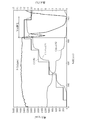
- nitrogen (N 2 ) is about 2000 cc / min and nitrogen monoxide (NO) is about While supplying a pseudo gas containing 5 cc / min, hydrogen (H 2 ) was temporarily supplied at 1.5 Vol.% (30 cc / min).
- the NOx concentration is about 2500 ppm in the stage before supplying hydrogen (H 2 ), whereas when the supply of hydrogen (H 2 ) starts, the NOx concentration suddenly reaches almost zero. Declined. Even after the supply of hydrogen (H 2 ) was stopped, the state where the NOx concentration was almost zero was maintained for a certain period, and then gradually increased.
- oxygen (O 2 ) concentration was decreased accordingly by increasing hydrogen (H 2 ) stepwise.
- H 2 hydrogen
- the metal foam catalyst having a predetermined temperature or higher exhibits NOx purification performance by functioning as hydrogen (H 2 ) as a reducing gas in a reducing atmosphere in which the oxygen concentration is almost zero. .
- the third test shown in FIG. 7 confirms the exhaust purification performance when carbon monoxide (CO) is used as the reducing gas.
- CO carbon monoxide
- N 2 nitrogen
- O 2 oxygen
- the third test while maintaining the inside of the metal foam catalyst at 535 to 545 ° C. with a heating device, nitrogen (N 2 ) is 1460 cc / min, air is 500 cc / min, oxygen (O 2 ) is supplied from the pseudo gas supply device. While supplying a pseudo gas containing about 5 Vol.% (2 cc / min) and 2600 ppm of nitric oxide (NO), the carbon monoxide (CO) concentration is increased by 200 ppm every predetermined period.
- the metal foam catalyst runs out of oxygen (O 2 ) and becomes a reducing atmosphere, not only hydrogen (H 2 ) but also carbon monoxide (CO) functions as a reducing gas, and NOx is decomposed significantly.
- the metal foam catalyst can be used not only for NOx but also for purification of carbon monoxide (CO).
- the fourth to sixth tests shown in FIGS. 8 to 10 confirm the exhaust purification performance when hydrocarbon (HC) is used as the reducing gas.
- HC hydrocarbon
- nitrogen (N 2 ) is 1460 cc / min
- air is 500 cc / min
- oxygen (O 2 ) is about 5 Vol.
- supplying a pseudo gas containing 2600 ppm of .2 (2 cc / min) and nitric oxide (NO) hydrocarbons (HC) are increased at regular intervals.
- methane (CH 4 ) of hydrocarbons (HC) is used as a reducing gas, and the methane (CH 4 ) concentration is increased by 1.5 to 3% at regular intervals. After reaching 10%, it was decreased by 1.5%. Then, as shown in FIG. 7, the concentration of methane (CH 4 ) was increased stepwise, and oxygen (O 2 ) decreased and carbon dioxide (CO 2 ) increased until it reached a certain level (9%) or more. When the oxygen (O 2 ) concentration became almost zero, the NOx concentration began to drop rapidly and became almost zero.
- propane (C 3 H 8 ) is used as a reducing gas in hydrocarbons (HC), and the propane (C 3 H 8 ) concentration is increased by about 1% every fixed period. After reaching%, it was decreased by 1%. Then, as shown in FIG. 8, when propane (C 3 H 8 ) increased stepwise, the oxygen (O 2 ) concentration decreased and the carbon dioxide (CO 2 ) concentration increased. When the oxygen (O 2 ) concentration became almost zero, the NOx concentration began to drop rapidly and reached almost zero.
- hydrocarbons such as methane (CH 4 ), propane (C 3 H 8 ), butane (C 4 H 10 )
- HC hydrocarbons
- methane (CH 4 ) propane (C 3 H 8 ), butane (C 4 H 10 )
- NOx is significantly decomposed.
- NOx purification performance is exhibited with a small quantity, so that carbon number increases among hydrocarbons (HC).
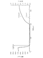
- FIG. 11 shows a graph showing the test results.
- a pseudo gas containing about 5 cc / min of nitrogen monoxide (NO), about 2000 cc / min of nitrogen (N 2 ), and 30 cc / min of hydrogen (H 2 ) is supplied from the pseudo gas supply device.
- the foamed catalyst metal was gradually heated by the heating device.
- the NOx concentration which was about 2300 ppm at the beginning, started to decrease from about 230 ° C. and became 10 ppm or less at about 380 ° C. From this, it can be seen that the foam metal catalyst starts to exhibit the exhaust purification performance from 230 ° C., and functions sufficiently as a catalyst particularly at 380 ° C. or higher.
- the exhaust gas can be purified without carrying a noble metal, and the exhaust gas purification performance can be maintained even in a high temperature state.
- the internal combustion engines 1, 11, and 21 are gasoline engines, but the internal combustion engine is not limited to a gasoline engine, and may be a diesel engine, for example.
- the exhaust gas purification system, catalyst, and exhaust gas purification method according to the present invention are not limited to application to an internal combustion engine, but are applied to heat engines including plants and external combustion engines that use hydrocarbon fuels. Can do.
- the exhaust gas purification system comprises a heat engine that exhausts exhaust gas, a transition metal element excluding a white metal element and a metal having a porosity of 80% or more, and is disposed in an exhaust gas passage of the heat engine. And a catalyst for reducing NOx by contacting with exhaust gas having a reducing gas concentration of a predetermined concentration or higher and 230 ° C. or higher.
- the exhaust gas purification system according to a second aspect of the present invention is the exhaust gas purification system according to the first aspect, wherein the reducing gas is hydrogen, and the hydrogen concentration of the exhaust gas discharged from the heat engine is adjusted to the predetermined concentration or more.
- a hydrogen concentration adjusting means to be sent to the catalyst is provided.
- the heat engine is disposed on the exhaust gas downstream side of the turbocharger having a turbine in the exhaust gas passage and the turbine.
- a three-way catalyst, and the catalyst is disposed on the exhaust gas upstream side of the three-way catalyst.
- the metal of the catalyst is a foam metal.
- the catalyst metal is formed by laminating mesh-like metals.
- the metal of the catalyst is nickel.
- the catalyst metal is stainless steel.
- the catalyst according to the eighth aspect of the present invention is composed of a transition metal element excluding a white metal element and a metal having a porosity of 80% or more. This reduces NOx.
- the metal is a foam metal.
- the metal is obtained by laminating mesh-like metals.
- the metal is nickel.
- the metal is stainless steel.
- the exhaust gas purification method comprises a transition metal element excluding a white metal element and pores in an exhaust gas passage of a heat engine in which a reducing gas has a predetermined concentration or more and an exhaust gas of 230 ° C. or more flows.
- a catalyst made of a metal with a rate of 80% or more is provided, and NOx in the exhaust gas is reduced by contacting the catalyst with exhaust gas having a concentration of the reducing gas equal to or higher than the predetermined concentration and 400 ° C. or higher.
Landscapes
- Chemical & Material Sciences (AREA)
- Engineering & Computer Science (AREA)
- Chemical Kinetics & Catalysis (AREA)
- Combustion & Propulsion (AREA)
- Health & Medical Sciences (AREA)
- Materials Engineering (AREA)
- General Engineering & Computer Science (AREA)
- Mechanical Engineering (AREA)
- Oil, Petroleum & Natural Gas (AREA)
- General Chemical & Material Sciences (AREA)
- Analytical Chemistry (AREA)
- Organic Chemistry (AREA)
- Environmental & Geological Engineering (AREA)
- Biomedical Technology (AREA)
- Toxicology (AREA)
- Exhaust Gas Treatment By Means Of Catalyst (AREA)
- Catalysts (AREA)
- Exhaust Gas After Treatment (AREA)
Abstract
Description


本発明の第1の態様に係る排ガス浄化システムは、排ガスを排出する熱機関と、白金属元素を除く遷移金属元素からなるとともに気孔率80%以上の金属からなり、前記熱機関の排ガス通路に設けられ、還元ガスの濃度が所定濃度以上であり且つ230℃以上である排ガスと接触することでNOxを還元する触媒と、を備えている。
2、12、22 排ガス通路
3 発泡金属触媒(触媒)
4 水素濃度調整部(水素濃度調整手段)
5 ターボチャージャ
6 三元触媒
Claims (13)
- 排ガスを排出する熱機関と、
白金属元素を除く遷移金属元素からなるとともに気孔率80%以上の金属からなり、前記熱機関の排ガス通路に設けられ、還元ガスの濃度が所定濃度以上であり且つ230℃以上である排ガスと接触することでNOxを還元する触媒と、
を備える排ガス浄化システム。 - 前記還元ガスは水素であり、前記熱機関から排出される排ガスの水素濃度を前記所定濃度以上に調整して前記触媒に送る水素濃度調整手段を備える請求項1記載の排ガス浄化システム。
- 前記熱機関は、排ガス通路にタービンを有するターボチャージャと、前記タービンより排ガス下流側に配設された三元触媒と、を備えており、
前記触媒は、前記三元触媒より排ガス上流側に配設される請求項1又は2記載の排ガス浄化システム。 - 前記触媒の金属は発泡金属からなる請求項1から3のいずれかに記載の排ガス浄化システム。
- 前記触媒の金属はメッシュ状の金属を積層させたものからなる請求項1から3のいずれかに記載の排ガス浄化システム。
- 前記触媒の金属はニッケルである請求項1から5のいずれかに記載の排ガス浄化システム。
- 前記触媒の金属はステンレス鋼である請求項1から5のいずれかに記載の排ガス浄化システム。
- 白金属元素を除く遷移金属元素からなるとともに気孔率80%以上の金属からなり、還元ガスの濃度が所定濃度以上であり且つ230℃以上の雰囲気下でNOxを還元する触媒。
- 前記金属は発泡金属である請求項8記載の触媒。
- 前記金属はメッシュ状の金属を積層させたものである請求項8記載の触媒。
- 前記金属はニッケルである請求項8から10のいずれかに記載の触媒。
- 前記金属はステンレス鋼である請求項8から10のいずれかに記載の触媒。
- 還元ガスが所定濃度以上であり且つ230℃以上の排ガスが流通する熱機関の排ガス通路に、白金属元素を除く遷移金属元素からなるとともに気孔率80%以上の金属からなる触媒を設け、
当該触媒に前記還元ガスの濃度が前記所定濃度以上であり且つ230℃以上の排ガスを接触させることで、当該排ガス中のNOxを還元する排ガス浄化方法。
Priority Applications (6)
| Application Number | Priority Date | Filing Date | Title |
|---|---|---|---|
| KR1020167029127A KR20160133560A (ko) | 2014-04-18 | 2015-03-30 | 배기가스 정화 시스템, 촉매, 및 배기가스 정화방법 |
| CA2944397A CA2944397A1 (en) | 2014-04-18 | 2015-03-30 | Exhaust gas purification system, catalyst, and exhaust gas purification method |
| JP2016513706A JPWO2015159698A1 (ja) | 2014-04-18 | 2015-03-30 | 排ガス浄化システム、触媒、及び排ガス浄化方法 |
| CN201580020386.5A CN106232208A (zh) | 2014-04-18 | 2015-03-30 | 废气净化系统、催化剂及废气净化方法 |
| US15/301,690 US20170113186A1 (en) | 2014-04-18 | 2015-03-30 | Exhaust gas purification system, catalyst, and exhaust gas purification method |
| EP15780175.4A EP3132841A4 (en) | 2014-04-18 | 2015-03-30 | Exhaust gas purification system, catalyst and exhaust gas purification method |
Applications Claiming Priority (2)
| Application Number | Priority Date | Filing Date | Title |
|---|---|---|---|
| JP2014-086426 | 2014-04-18 | ||
| JP2014086426 | 2014-04-18 |
Publications (1)
| Publication Number | Publication Date |
|---|---|
| WO2015159698A1 true WO2015159698A1 (ja) | 2015-10-22 |
Family
ID=54323909
Family Applications (1)
| Application Number | Title | Priority Date | Filing Date |
|---|---|---|---|
| PCT/JP2015/059969 Ceased WO2015159698A1 (ja) | 2014-04-18 | 2015-03-30 | 排ガス浄化システム、触媒、及び排ガス浄化方法 |
Country Status (7)
| Country | Link |
|---|---|
| US (1) | US20170113186A1 (ja) |
| EP (1) | EP3132841A4 (ja) |
| JP (2) | JP2015212541A (ja) |
| KR (1) | KR20160133560A (ja) |
| CN (1) | CN106232208A (ja) |
| CA (1) | CA2944397A1 (ja) |
| WO (1) | WO2015159698A1 (ja) |
Families Citing this family (5)
| Publication number | Priority date | Publication date | Assignee | Title |
|---|---|---|---|---|
| JP6599161B2 (ja) | 2015-08-05 | 2019-10-30 | 株式会社クボタ | 排気浄化装置 |
| CN107672439B (zh) * | 2017-08-18 | 2020-10-27 | 广东卓梅尼技术股份有限公司 | 一种氢混合动力集成控制系统 |
| JP2019172540A (ja) * | 2018-03-29 | 2019-10-10 | 太平洋マテリアル株式会社 | カルシウムアルミネート粉末の製造方法 |
| JP7040978B2 (ja) * | 2018-03-29 | 2022-03-23 | 太平洋マテリアル株式会社 | カルシウムアルミネート粉末 |
| CN110180382A (zh) * | 2019-04-17 | 2019-08-30 | 余姚市电波机械有限公司 | 一种氮氧化物催化反应网 |
Citations (10)
| Publication number | Priority date | Publication date | Assignee | Title |
|---|---|---|---|---|
| JPS4948546A (ja) * | 1972-05-11 | 1974-05-10 | ||
| JPS4981291A (ja) * | 1972-11-13 | 1974-08-06 | ||
| JPS54142174A (en) * | 1978-04-28 | 1979-11-06 | Hitachi Ltd | Removing nox in waste gas |
| JPS5567336A (en) * | 1978-11-16 | 1980-05-21 | Mitsubishi Heavy Ind Ltd | Preparation of catalyst |
| JPS574235A (en) * | 1980-06-12 | 1982-01-09 | Toru Mashida | Catalytic device |
| JPS62117620A (ja) * | 1985-11-19 | 1987-05-29 | Nippon Shokubai Kagaku Kogyo Co Ltd | ガソリンエンジン排ガス中の窒素酸化物を除去する方法 |
| JPH0796145A (ja) * | 1993-06-10 | 1995-04-11 | Inco Ltd | 内燃機関排気ガスの接触転化 |
| JPH10212938A (ja) * | 1997-01-31 | 1998-08-11 | Yamaha Motor Co Ltd | 内燃機関の排気ガス浄化装置 |
| JP2001234737A (ja) * | 1999-10-21 | 2001-08-31 | Nissan Motor Co Ltd | 排気ガス浄化システム |
| WO2010106695A1 (ja) * | 2009-03-19 | 2010-09-23 | トヨタ自動車株式会社 | 内燃機関の排気浄化装置 |
Family Cites Families (15)
| Publication number | Priority date | Publication date | Assignee | Title |
|---|---|---|---|---|
| US3111396A (en) * | 1960-12-14 | 1963-11-19 | Gen Electric | Method of making a porous material |
| US3773894A (en) * | 1971-07-22 | 1973-11-20 | Exxon | Nitrogen oxide conversion using reinforced nickel-copper catalysts |
| JPS5230957B2 (ja) * | 1972-02-12 | 1977-08-11 | ||
| US3988263A (en) * | 1974-10-02 | 1976-10-26 | Union Oil Company Of California | Thermally stable coprecipitated catalysts useful for methanation and other reactions |
| JPS51110491A (en) * | 1975-03-26 | 1976-09-30 | Ube Industries | Nox kangenjokayoshokubai |
| JPS5945421B2 (ja) * | 1976-10-16 | 1984-11-06 | 工業技術院長 | 窒素酸化物還元用金属炭化物基触媒の再生方法 |
| FI89463C (fi) * | 1991-01-03 | 1993-10-11 | Kemira Oy | Anvaendning av en nickelbaserad, aluminium innehaollande metallegering som substratmaterial foer en avgaser renande katalysator |
| US6887438B2 (en) * | 2000-12-21 | 2005-05-03 | Delphi Technologies, Inc. | NOx control |
| JP4173986B2 (ja) * | 2002-11-14 | 2008-10-29 | 本田技研工業株式会社 | ハニカム構造体の溶接方法 |
| CN100338341C (zh) * | 2003-04-30 | 2007-09-19 | 比亚迪股份有限公司 | 汽车尾气催化转化器 |
| JP5144220B2 (ja) * | 2007-11-08 | 2013-02-13 | 本田技研工業株式会社 | 内燃機関の排気浄化装置 |
| JP5568865B2 (ja) * | 2009-02-05 | 2014-08-13 | 住友電気工業株式会社 | ガス分解素子 |
| JP5376450B2 (ja) | 2009-12-28 | 2013-12-25 | 三菱重工業株式会社 | 排ガス浄化方法 |
| JP5331177B2 (ja) * | 2011-01-14 | 2013-10-30 | トヨタ自動車株式会社 | 内燃機関の卑金属排ガス浄化装置 |
| US8506912B1 (en) * | 2012-02-07 | 2013-08-13 | Ford Global Technologies, Llc | Exhaust treatment system including a nickel-based catalyst |
-
2015
- 2015-03-30 CN CN201580020386.5A patent/CN106232208A/zh active Pending
- 2015-03-30 CA CA2944397A patent/CA2944397A1/en not_active Abandoned
- 2015-03-30 WO PCT/JP2015/059969 patent/WO2015159698A1/ja not_active Ceased
- 2015-03-30 KR KR1020167029127A patent/KR20160133560A/ko not_active Ceased
- 2015-03-30 JP JP2015069372A patent/JP2015212541A/ja active Pending
- 2015-03-30 EP EP15780175.4A patent/EP3132841A4/en not_active Withdrawn
- 2015-03-30 US US15/301,690 patent/US20170113186A1/en not_active Abandoned
- 2015-03-30 JP JP2016513706A patent/JPWO2015159698A1/ja active Pending
Patent Citations (10)
| Publication number | Priority date | Publication date | Assignee | Title |
|---|---|---|---|---|
| JPS4948546A (ja) * | 1972-05-11 | 1974-05-10 | ||
| JPS4981291A (ja) * | 1972-11-13 | 1974-08-06 | ||
| JPS54142174A (en) * | 1978-04-28 | 1979-11-06 | Hitachi Ltd | Removing nox in waste gas |
| JPS5567336A (en) * | 1978-11-16 | 1980-05-21 | Mitsubishi Heavy Ind Ltd | Preparation of catalyst |
| JPS574235A (en) * | 1980-06-12 | 1982-01-09 | Toru Mashida | Catalytic device |
| JPS62117620A (ja) * | 1985-11-19 | 1987-05-29 | Nippon Shokubai Kagaku Kogyo Co Ltd | ガソリンエンジン排ガス中の窒素酸化物を除去する方法 |
| JPH0796145A (ja) * | 1993-06-10 | 1995-04-11 | Inco Ltd | 内燃機関排気ガスの接触転化 |
| JPH10212938A (ja) * | 1997-01-31 | 1998-08-11 | Yamaha Motor Co Ltd | 内燃機関の排気ガス浄化装置 |
| JP2001234737A (ja) * | 1999-10-21 | 2001-08-31 | Nissan Motor Co Ltd | 排気ガス浄化システム |
| WO2010106695A1 (ja) * | 2009-03-19 | 2010-09-23 | トヨタ自動車株式会社 | 内燃機関の排気浄化装置 |
Non-Patent Citations (1)
| Title |
|---|
| See also references of EP3132841A4 * |
Also Published As
| Publication number | Publication date |
|---|---|
| EP3132841A1 (en) | 2017-02-22 |
| CN106232208A (zh) | 2016-12-14 |
| JP2015212541A (ja) | 2015-11-26 |
| US20170113186A1 (en) | 2017-04-27 |
| JPWO2015159698A1 (ja) | 2017-04-13 |
| CA2944397A1 (en) | 2015-10-22 |
| KR20160133560A (ko) | 2016-11-22 |
| EP3132841A4 (en) | 2017-11-22 |
Similar Documents
| Publication | Publication Date | Title |
|---|---|---|
| WO2015159698A1 (ja) | 排ガス浄化システム、触媒、及び排ガス浄化方法 | |
| GR1005904B (el) | Καταλυτικο φιλτρο μεταλλικου αφρου για το καυσαεριο των κινητηρων ντηζελ. | |
| JP2020045860A (ja) | 排ガス浄化装置 | |
| KR20130139995A (ko) | 연료 개질기 | |
| KR101546332B1 (ko) | 연소 시스템 배기물로부터 no₂를 감소시키기 위한 프로세스 | |
| CN101614147B (zh) | 内燃机的排气净化装置 | |
| JP2021173212A (ja) | 水素燃料エンジンの排気浄化システム | |
| JP4631902B2 (ja) | 排ガス浄化装置 | |
| JP2020045862A (ja) | 排ガス浄化装置 | |
| JP4704964B2 (ja) | NOx浄化システム及びNOx浄化方法 | |
| CN107534172B (zh) | 带发电功能的排气净化系统 | |
| JP5476770B2 (ja) | 排気ガス浄化システム及び排気ガス浄化システムの制御方法 | |
| KR20210014510A (ko) | 메탄 산화 촉매 재생 시스템 및 이를 포함하는 메탄 산화 반응 장치 | |
| JP5476771B2 (ja) | 排気ガス浄化システム及び排気ガス浄化システムの制御方法 | |
| JP7485136B1 (ja) | 浄化システム | |
| JP2001327838A (ja) | ディーゼルエンジンの排気浄化装置 | |
| JP7472454B2 (ja) | 暖機制御方法 | |
| JP2025034090A (ja) | 排気浄化システム | |
| JP2020045861A (ja) | 排ガス浄化装置 | |
| KR20230035886A (ko) | 연료 개질 시스템 | |
| KR101826561B1 (ko) | 배기가스 후처리 시스템 및 플라즈마 이용 촉매 재생방법 | |
| JP5293337B2 (ja) | 内燃機関及び内燃機関の制御方法 | |
| JP2017110499A (ja) | 内燃機関の排気ガス浄化システム及び内燃機関の排気ガス浄化方法 | |
| US20060242906A1 (en) | Reformer system and method of operating the same | |
| JP2022003245A (ja) | 水素燃料エンジンの排気浄化システム |
Legal Events
| Date | Code | Title | Description |
|---|---|---|---|
| 121 | Ep: the epo has been informed by wipo that ep was designated in this application |
Ref document number: 15780175 Country of ref document: EP Kind code of ref document: A1 |
|
| ENP | Entry into the national phase |
Ref document number: 2016513706 Country of ref document: JP Kind code of ref document: A |
|
| ENP | Entry into the national phase |
Ref document number: 2944397 Country of ref document: CA |
|
| WWE | Wipo information: entry into national phase |
Ref document number: 15301690 Country of ref document: US |
|
| NENP | Non-entry into the national phase |
Ref country code: DE |
|
| REEP | Request for entry into the european phase |
Ref document number: 2015780175 Country of ref document: EP |
|
| WWE | Wipo information: entry into national phase |
Ref document number: 2015780175 Country of ref document: EP |
|
| ENP | Entry into the national phase |
Ref document number: 20167029127 Country of ref document: KR Kind code of ref document: A |