WO2015163033A1 - Système radio - Google Patents
Système radio Download PDFInfo
- Publication number
- WO2015163033A1 WO2015163033A1 PCT/JP2015/057518 JP2015057518W WO2015163033A1 WO 2015163033 A1 WO2015163033 A1 WO 2015163033A1 JP 2015057518 W JP2015057518 W JP 2015057518W WO 2015163033 A1 WO2015163033 A1 WO 2015163033A1
- Authority
- WO
- WIPO (PCT)
- Prior art keywords
- conversion circuit
- polarization conversion
- polarization
- antenna
- rotation angle
- Prior art date
- Legal status (The legal status is an assumption and is not a legal conclusion. Google has not performed a legal analysis and makes no representation as to the accuracy of the status listed.)
- Ceased
Links
Images






Classifications
-
- H—ELECTRICITY
- H01—ELECTRIC ELEMENTS
- H01Q—ANTENNAS, i.e. RADIO AERIALS
- H01Q15/00—Devices for reflection, refraction, diffraction or polarisation of waves radiated from an antenna, e.g. quasi-optical devices
- H01Q15/24—Polarising devices; Polarisation filters
- H01Q15/242—Polarisation converters
- H01Q15/246—Polarisation converters rotating the plane of polarisation of a linear polarised wave
-
- H—ELECTRICITY
- H01—ELECTRIC ELEMENTS
- H01P—WAVEGUIDES; RESONATORS, LINES, OR OTHER DEVICES OF THE WAVEGUIDE TYPE
- H01P1/00—Auxiliary devices
- H01P1/165—Auxiliary devices for rotating the plane of polarisation
-
- H—ELECTRICITY
- H01—ELECTRIC ELEMENTS
- H01P—WAVEGUIDES; RESONATORS, LINES, OR OTHER DEVICES OF THE WAVEGUIDE TYPE
- H01P5/00—Coupling devices of the waveguide type
- H01P5/04—Coupling devices of the waveguide type with variable factor of coupling
-
- H—ELECTRICITY
- H01—ELECTRIC ELEMENTS
- H01Q—ANTENNAS, i.e. RADIO AERIALS
- H01Q1/00—Details of, or arrangements associated with, antennas
- H01Q1/12—Supports; Mounting means
- H01Q1/20—Resilient mountings
-
- H—ELECTRICITY
- H01—ELECTRIC ELEMENTS
- H01Q—ANTENNAS, i.e. RADIO AERIALS
- H01Q1/00—Details of, or arrangements associated with, antennas
- H01Q1/12—Supports; Mounting means
- H01Q1/22—Supports; Mounting means by structural association with other equipment or articles
- H01Q1/24—Supports; Mounting means by structural association with other equipment or articles with receiving set
-
- H—ELECTRICITY
- H01—ELECTRIC ELEMENTS
- H01Q—ANTENNAS, i.e. RADIO AERIALS
- H01Q1/00—Details of, or arrangements associated with, antennas
- H01Q1/12—Supports; Mounting means
- H01Q1/22—Supports; Mounting means by structural association with other equipment or articles
- H01Q1/24—Supports; Mounting means by structural association with other equipment or articles with receiving set
- H01Q1/241—Supports; Mounting means by structural association with other equipment or articles with receiving set used in mobile communications, e.g. GSM
- H01Q1/246—Supports; Mounting means by structural association with other equipment or articles with receiving set used in mobile communications, e.g. GSM specially adapted for base stations
-
- H—ELECTRICITY
- H01—ELECTRIC ELEMENTS
- H01Q—ANTENNAS, i.e. RADIO AERIALS
- H01Q3/00—Arrangements for changing or varying the orientation or the shape of the directional pattern of the waves radiated from an antenna or antenna system
- H01Q3/02—Arrangements for changing or varying the orientation or the shape of the directional pattern of the waves radiated from an antenna or antenna system using mechanical movement of antenna or antenna system as a whole
- H01Q3/04—Arrangements for changing or varying the orientation or the shape of the directional pattern of the waves radiated from an antenna or antenna system using mechanical movement of antenna or antenna system as a whole for varying one co-ordinate of the orientation
- H01Q3/06—Arrangements for changing or varying the orientation or the shape of the directional pattern of the waves radiated from an antenna or antenna system using mechanical movement of antenna or antenna system as a whole for varying one co-ordinate of the orientation over a restricted angle
Definitions
- the present invention relates to a wireless system including a polarization conversion circuit between a wireless device and an antenna device.
- a wireless device transmitter / receiver
- an antenna device are connected via a waveguide, and microwaves, millimeter waves, etc. are connected by the waveguide.
- RF (Radio frequency) signal is transmitted.
- horizontal polarization, vertical polarization, and 45 degree polarization in linear polarization are often used properly as RF signals transmitted and received via the antenna device. Therefore, the vibration direction (horizontal, vertical, or 45 degrees) between the polarization of the RF signal traveling in the antenna element or the waveguide included in the antenna device and the polarization of the RF signal traveling in the waveguide included in the wireless device. ) May be different.
- a known polarization conversion circuit is inserted between the wireless device and the antenna device to change the vibration direction of the polarization. Change it.
- a configuration example of the polarization conversion circuit is described in Patent Document 1, for example.
- FIG. 1A is a side sectional view showing a configuration of a wireless system related to the present invention
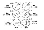
- FIG. 1B is a view of the wireless system shown in FIG. 1A from the AA ′ line, the BB ′ line, and the CC line.
- FIG. 1A In the wireless system of the background art, each of the wireless device and the antenna device has a waveguide (not shown), and the wireless device and the antenna device are fixed by abutting and fixing the open ends of the respective waveguides. It is a configuration to be connected.
- the contact portion of the wireless device with the antenna device is referred to as “device interface portion”, and the contact portion of the antenna device with the wireless device is referred to as “antenna interface portion”.
- FIG. 1A shows a configuration example of these device interface unit 101 and antenna interface unit 102, and a connection example thereof.
- the polarization conversion circuit 103 is provided on the opening end side of the device interface unit 101 so as to be positioned between the waveguide included in the wireless device and the waveguide included in the antenna device. It is installed in the storage unit 104.
- the contact surface between the device interface unit 101 and the antenna interface unit 102 is sealed with a ring-shaped gasket 105 or the like in order to ensure the airtightness of a radio device or an antenna device installed outdoors.
- FIG. 1A shows a configuration example of these device interface unit 101 and antenna interface unit 102, and a connection example thereof.
- the polarization conversion circuit 103 is provided on the opening end side of the device interface unit 101 so as to be positioned between the waveguide included in the wireless device and the waveguide included in the antenna device. It is installed in the storage unit 104.
- the contact surface between the device interface unit 101 and the antenna interface unit 102 is sealed with a
- FIG. 1B shows an example of the shape of the waveguide or polarization conversion circuit 103 viewed from the opening end side in the device interface unit 101 or the antenna interface unit 102, respectively.
- a rectangular hole in each circle showing the outer shape of the waveguide or polarization conversion circuit 103 in FIG. 1B is an RF signal transmission path.
- a hole penetrating the device interface unit 101, the antenna interface unit 102, and the polarization conversion circuit 103 is a transmission path for the RF signal.
- 1B indicates the device interface unit 101
- “conversion” indicates the polarization conversion circuit 103
- “antenna” indicates the antenna interface unit 102.
- the polarization conversion circuit 103 is set at such an angle that the RF signal is not reflected at the input / output end while rotating the oscillation direction of the polarization.
- the rotation angle ⁇ is set to +22.5 degrees
- the rotation angle ⁇ is set to +67.5 degrees. Is done.
- a polarization conversion circuit is often incorporated in the wireless device in order to ensure the airtightness of the wireless device and the antenna device installed outdoors. For this reason, a configuration in which a wireless device or an antenna device cannot visually recognize a polarization conversion circuit from the outside is common. Therefore, in the wireless system of the background art, for example, when the wireless system is installed, if the wireless device and the antenna device are connected, the rotation angle of the polarization conversion circuit cannot be confirmed from the outside.
- the polarization conversion circuit is fixed in advance to the device interface unit at a predetermined rotation angle corresponding to the relationship between the polarization of the wireless device and the antenna device.
- a predetermined rotation angle corresponding to the relationship between the polarization of the wireless device and the antenna device.
- an object of the present invention is to provide a wireless system that enables confirmation of the rotation angle of the polarization conversion circuit from the outside.
- a wireless system of the present invention includes a wireless device, An antenna device; The vibration of the polarization inserted between the radio apparatus and the antenna apparatus in order to match the vibration direction of the polarization of an RF (Radio frequency) signal transmitted in the radio apparatus and the antenna apparatus.
- Have The polarization conversion circuit is installed in a storage unit provided in a device interface unit that is a contact portion with the antenna device in the wireless device,
- the device interface unit is A through-hole that reaches the outer periphery of the polarization conversion circuit from the outer wall of the device interface unit is used for confirming the rotation angle of the polarization conversion circuit in the storage unit.
- An antenna device Or with a wireless device, An antenna device; The vibration of the polarization inserted between the radio apparatus and the antenna apparatus in order to match the vibration direction of the polarization of an RF (Radio frequency) signal transmitted in the radio apparatus and the antenna apparatus.
- a polarization conversion circuit for changing the direction; Have The polarization conversion circuit is installed in a storage unit provided in a device interface unit that is a contact portion with the antenna device in the wireless device, The storage section is A notch that exposes a part of the outer periphery of the polarization conversion circuit to the outside, In the outer periphery of the polarization conversion circuit, a convex portion or a concave portion that is visible from the outside by the notch portion is provided.
- An antenna device An antenna device; The vibration of the polarization fixed between the radio apparatus and the antenna apparatus in order to match the vibration direction of the polarization of an RF (Radio frequency) signal transmitted in the radio apparatus and the antenna apparatus.
- a polarization conversion circuit for changing the direction; Have The polarization conversion circuit is: The contact surface with the wireless device has the same shape as the antenna interface unit that is the contact portion with the wireless device in the antenna device, and the contact surface with the antenna device is in contact with the antenna device in the wireless device. It is the same shape as the device interface part that is the contact part, In this configuration, a label or a stamp for identifying the rotation angle of the polarization conversion circuit is provided on the outer periphery of the polarization conversion circuit.
- FIG. 1A is a side sectional view showing a configuration of a wireless system related to the present invention.
- FIG. 1B is a schematic diagram showing a cross-sectional shape of the wireless system shown in FIG. 1A viewed from the A-A ′ line, the B-B ′ line, and the CC line.
- FIG. 2A is a side sectional view showing a configuration example of the wireless system according to the first embodiment.
- 2B is a schematic diagram illustrating an example of a cross-sectional shape of the wireless system illustrated in FIG. 2A.
- FIG. 3A is a side sectional view illustrating a configuration example of a wireless system according to the second embodiment.
- 3B is a schematic diagram illustrating an example of a cross-sectional shape of the wireless system illustrated in FIG. 3A.
- FIG. 4A is a side sectional view illustrating a configuration example of a wireless system according to the third embodiment.
- 4B is a schematic diagram illustrating an example of a cross-sectional shape of the wireless system illustrated in FIG. 4A.
- FIG. 5 is a side sectional view showing a configuration example of the wireless system according to the fourth embodiment.
- FIG. 6A is a side sectional view illustrating a configuration example of a wireless system according to the fifth embodiment.
- FIG. 6B is a schematic diagram illustrating an example of the rotation angle of the polarization conversion circuit viewed from the antenna device.
- FIG. 7 is a side sectional view showing a configuration example of the wireless system according to the sixth embodiment.
- FIG. 2A is a side sectional view showing a configuration example of the wireless system according to the first embodiment
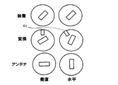
- FIG. 2B is a schematic diagram showing an example of a sectional shape of the wireless system shown in FIG. 2A.
- 2B shows the AA ′ line, the BB ′ line, and the CC line shown in FIG. 1A for the antenna interface unit 2, the polarization conversion circuit 3, and the device interface unit 1, as in FIG. 1B.
- 2 shows an example of a cross-sectional shape viewed from the same direction.
- 2B indicates the device interface unit 1
- conversion indicates the polarization conversion circuit 3
- “antenna” indicates the antenna interface unit 2.
- FIGS. 1 is a side sectional view showing a configuration example of the wireless system according to the first embodiment
- FIG. 2B is a schematic diagram showing an example of a sectional shape of the wireless system shown in FIG. 2A.
- 2B shows the AA ′ line, the BB ′ line, and the CC line shown in FIG.
- the radio system according to the first embodiment is housed in which the polarization conversion circuit 3 is provided in the device interface unit 1 in the same manner as the radio system of the background art shown in FIG. 1A.
- This is a configuration installed in the section 15.
- the device interface unit 1 is provided with a through-hole 41 that reaches the outer periphery of the polarization conversion circuit 3 from the outer wall of the device interface unit 1 and is used for confirming the rotation angle of the polarization conversion circuit 3 in the storage unit 15. ing.
- the polarization conversion circuit 3, a hole 4 2 is provided on its outer periphery.
- the screw 5 is provided with a packing 6 at a portion that contacts the device interface unit 1 in order to ensure airtightness in the wireless device.
- Holes 4 2 provided on the outer periphery of the polarization converter 3 is a concave shape which does not reach the transmission path of the RF signal, when the polarization conversion circuit 3 of a predetermined rotation angle, be a position that communicates with the through hole 4 1 and it is formed with an opening diameter which communicates with the through hole 4 1.
- Holes 4 2 has a larger opening diameter than the through-holes 4 1, may be sized to not through holes 4 1 and communicating when switching the rotation angle of the polarization converter 3.
- Other configurations are the same as those of the wireless system of the background art shown in FIGS.
- the through hole 41 of the device interface unit 1 and the polarization conversion circuit 3 periphery and holes 4 2 indicates an example in which the insertion length of the pin is longer communicates the.
- the through holes 4 1 to the apparatus interface unit 1 is provided, by providing the hole 4 2 on the outer periphery of the polarization conversion circuit 3, the insertion of the pin to be inserted into the through-hole 4 1 of device interface 1
- the rotation angle of the polarization conversion circuit 3 can be determined by the length. Therefore, the rotation angle of the polarization conversion circuit 3 can be confirmed from the outside even when the antenna device is connected to the wireless device. As a result, it is not necessary to remove the antenna device again in order to confirm the rotation angle of the polarization conversion circuit after connecting the wireless device and the antenna device. Further, by confirming the rotation angle of the polarization conversion circuit 3 from the outside, it is possible to prevent a connection error between the wireless device and the antenna device.
- FIG. 3A is a side sectional view showing a configuration example of the wireless system according to the second embodiment
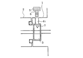
- FIG. 3B is a schematic view showing an example of a sectional shape of the wireless system shown in FIG. 3A.
- 3B shows the AA ′ line, the BB ′ line, and the CC line shown in FIG. 1A for the antenna interface unit 2, the polarization conversion circuit 3, and the device interface unit 1, as in FIG. 2B. 2 shows an example of a cross-sectional shape viewed from the same direction.
- 3B indicates the device interface unit 1
- conversion indicates the polarization conversion circuit 3
- “antenna” indicates the antenna interface unit 2.
- FIGS. 1 is a side sectional view showing a configuration example of the wireless system according to the second embodiment
- FIG. 3B is a schematic view showing an example of a sectional shape of the wireless system shown in FIG. 3A.
- 3B shows the AA ′ line, the BB ′ line, and the CC line shown in FIG. 1A
- the radio system of the second embodiment the outer periphery of the polarization conversion circuit 3, in place of the hole 4 2 shown in the first embodiment, the polarization converter 3
- a label (or engraving) 7 indicating the rotation angle is provided.
- Label (or engraved) 7 when the polarization conversion circuit 3 of a predetermined rotation angle, may be provided to the position of the outer circumference corresponding to the position of the through-hole 4 1 of device interface 1.
- the label (or inscription) 7 only needs to be able to identify the rotation angle of the polarization conversion circuit 3, and may display the vibration direction of the converted polarization.
- the other configuration is the same as that of the wireless system according to the first embodiment shown in FIGS. 2A and 2B, and the description thereof is omitted.
- Figure 3B is a polarization conversion circuit 3, when a rotation angle for conversion from 45 ° polarized RF signals to vertical polarization, the outer periphery of the polarization converter 3 corresponding to the position of the through-holes 4 1 An example in which a label (V) 7 is attached to the position is shown. Further, FIG. 3B, the polarization conversion circuit 3, when a rotation angle for conversion from 45 ° polarized RF signals to horizontal polarization, the polarization converter 3 corresponding to the position of the through-holes 4 1 An example in which a label (H) 7 is affixed to an outer peripheral position is shown.
- FIG. 4A is a side sectional view showing a configuration example of the wireless system according to the third embodiment
- FIG. 4B is a schematic diagram showing an example of a sectional shape of the wireless system shown in FIG. 4A.
- 4B shows the AA ′ line, the BB ′ line, and the CC line shown in FIG. 1A for the antenna interface unit 2, the polarization conversion circuit 3, and the device interface unit 1, as in FIG. 3B. 2 shows an example of a cross-sectional shape viewed from the same direction.
- 4B indicates the device interface unit 1
- conversion indicates the polarization conversion circuit 3
- “antenna” indicates the antenna interface unit 2.
- FIGS. 1 is a side sectional view showing a configuration example of the wireless system according to the third embodiment
- FIG. 4B is a schematic diagram showing an example of a sectional shape of the wireless system shown in FIG. 4A.
- 4B shows the AA ′ line, the BB ′ line, and the CC line shown in FIG. 1A
- the wireless system of the third embodiment has an arbitrary outer periphery of the polarization conversion circuit 3 in place of the label (or engraving) 7 shown in the second embodiment. It is the structure provided with the application part 8 by which the color was apply
- the other configuration is the same as that of the wireless system according to the second embodiment shown in FIG.
- FIG. 5 is a side sectional view showing a configuration example of the wireless system according to the fourth embodiment.
- the wireless system of the fourth embodiment is replaced with the screw 5 shown in the first embodiment in the configuration shown in the second embodiment or the third embodiment.
- Te is closes the through-hole 4 1 of device interface 1 constructed using a cover 9.
- the cover 9 may be formed using a resin such as plastic or acrylic, and is more preferably transparent.
- Other configurations are the same as those of the wireless system of the second embodiment shown in FIG. 3 or the third embodiment shown in FIGS.
- the color of the label (or stamp) 7 of the polarization conversion circuit 3 or the color of the application unit 8 is removed by removing the cover 9 or passing through the transparent cover 9 as in the second and third embodiments.
- the rotation angle of the polarization conversion circuit 3 can be determined. Therefore, also in the wireless system of the fourth embodiment, the rotation angle of the polarization conversion circuit 3 can be confirmed from the outside of the wireless device, and the same effect as that of the first embodiment can be obtained. it can.
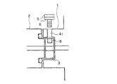
- FIG. 6A is a side cross-sectional view illustrating a configuration example of the wireless system according to the fifth embodiment
- FIG. 6B is a schematic diagram illustrating an example of the rotation angle of the polarization conversion circuit viewed from the antenna device.
- “Vertical polarization” shown in FIG. 6B shows a state in which the polarization conversion circuit 3 is set to a rotation angle for converting 45-degree polarization to vertical polarization.
- “horizontal polarization” shown in FIG. 6B indicates a state in which the polarization conversion circuit 3 is set to a rotation angle for converting 45-degree polarization to horizontal polarization.
- the notch 11 that exposes a part of the outer periphery of the polarization conversion circuit 3 to the outside in the housing 15 provided in the device interface 1. It is the structure provided.
- a convex portion 12 or a concave portion 13 is provided on the outer periphery of the polarization conversion circuit 3.
- the convex portion 12 or the concave portion 13 of the polarization conversion circuit 3 is formed at a position visible from the outside by the notch portion 11.
- FIG. 6A shows a configuration example in which the convex portion 12 is provided on the outer periphery of the polarization conversion circuit 3.
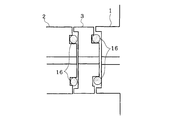
- the contact surface between the device interface unit 1 and the antenna interface unit 2 is provided with a ring-shaped gasket 16 or the like at a position away from the notch 11 in order to ensure the airtightness of the radio device or antenna device installed outdoors. It is sealed using. Since other configurations are the same as those of the wireless system of the background art shown in FIG. In such a configuration, as shown in FIG. 6B, the rotation angle of the polarization conversion circuit 3 can be confirmed by the direction of the convex portion 12 or the concave portion 13 provided on the outer periphery of the polarization conversion circuit 3.
- a label or a stamp for identifying the rotation angle of the polarization conversion circuit 3 or the vibration direction of the polarization after conversion may be provided at both ends of the notch 11. Therefore, also in the wireless system of the fifth embodiment, the rotation angle of the polarization conversion circuit 3 can be confirmed from the outside of the wireless device, and the same effect as in the first embodiment can be obtained. it can. Further, in the wireless system of the fifth embodiment, if the polarization conversion circuit 3 is rotatably held by the storage unit 15, the polarization conversion circuit 3 can be connected even when the antenna device is connected to the wireless device. Can be rotated. Therefore, switching of the vibration direction of the polarization of the RF signal by the polarization conversion circuit 3 can be easily performed from the outside.
- FIG. 7 is a side sectional view showing a configuration example of the wireless system according to the sixth embodiment.
- the radio system according to the sixth embodiment has a configuration in which the polarization conversion circuit 3 is fixed between the device interface unit 1 and the antenna interface unit 2.
- the contact surface with the radio device in the polarization conversion circuit 3 has the same shape as the antenna interface unit 2
- the contact surface with the antenna device in the polarization conversion circuit 3 has the same shape as the device interface unit 1.
- the polarization conversion circuit 3 can be fixed between the wireless device and the antenna device without changing the existing device interface unit 1 and antenna interface unit 2.
- the portions where the polarization conversion circuit 3 is in contact with the device interface unit 1 and the antenna interface unit 2 are sealed using, for example, a ring-shaped gasket 16 to ensure the airtightness of the wireless device and the antenna device.
- a label (or engraving) 7 indicating the polarization vibration direction as in the second embodiment, or the polarization vibration direction as in the third embodiment.
- the application part 8 to which a different color is applied is provided. Since other configurations are the same as those of the wireless system of the background art shown in FIG.
- the rotation angle of the polarization conversion circuit 3 can be confirmed by whether or not the label (V or H) 7 provided on the outer periphery of the polarization conversion circuit 3 is at a predetermined position.
- the rotation angle of the polarization conversion circuit 3 can be confirmed by the color of the application unit 8 at a predetermined position. Therefore, also in the wireless system of the sixth embodiment, the rotation angle of the polarization conversion circuit 3 can be confirmed from the outside of the wireless device, and the same effect as that of the first embodiment can be obtained. it can.
Landscapes
- Engineering & Computer Science (AREA)
- Computer Networks & Wireless Communication (AREA)
- Variable-Direction Aerials And Aerial Arrays (AREA)
- Support Of Aerials (AREA)
- Arrangements For Transmission Of Measured Signals (AREA)
- Transceivers (AREA)
Abstract
L'invention concerne un système radio comprenant un appareil radio, un appareil formant antenne et un circuit de conversion de polarisation qui est inséré dans une partie reliant l'appareil radio à l'appareil formant antenne et qui change la direction d'oscillation d'ondes polarisées. Le circuit de conversion de polarisation est placé dans une partie boîtier réalisée sur une partie formant interface d'appareil. La partie formant interface d'appareil possède un trou traversant qui est utilisé pour reconnaître un angle de rotation du circuit de conversion de polarisation dans la partie boîtier et qui s'étend d'une paroi externe de la partie formant interface d'appareil à la périphérie du circuit de conversion de polarisation.
Priority Applications (1)
| Application Number | Priority Date | Filing Date | Title |
|---|---|---|---|
| US15/303,854 US10177458B2 (en) | 2014-04-24 | 2015-03-13 | Radio system |
Applications Claiming Priority (2)
| Application Number | Priority Date | Filing Date | Title |
|---|---|---|---|
| JP2014-089939 | 2014-04-24 | ||
| JP2014089939 | 2014-04-24 |
Publications (1)
| Publication Number | Publication Date |
|---|---|
| WO2015163033A1 true WO2015163033A1 (fr) | 2015-10-29 |
Family
ID=54332204
Family Applications (1)
| Application Number | Title | Priority Date | Filing Date |
|---|---|---|---|
| PCT/JP2015/057518 Ceased WO2015163033A1 (fr) | 2014-04-24 | 2015-03-13 | Système radio |
Country Status (2)
| Country | Link |
|---|---|
| US (1) | US10177458B2 (fr) |
| WO (1) | WO2015163033A1 (fr) |
Families Citing this family (2)
| Publication number | Priority date | Publication date | Assignee | Title |
|---|---|---|---|---|
| US10756417B2 (en) * | 2017-12-14 | 2020-08-25 | Waymo Llc | Adaptive polarimetric radar architecture for autonomous driving |
| JP7413672B2 (ja) * | 2019-07-25 | 2024-01-16 | 日本電気株式会社 | アンテナ装置、無線送信機、無線受信機、及び無線通信システム |
Citations (6)
| Publication number | Priority date | Publication date | Assignee | Title |
|---|---|---|---|---|
| JPS52147047A (en) * | 1976-06-01 | 1977-12-07 | Mitsubishi Electric Corp | Arbitrary angle torsion wave guide for electromagnetic wave |
| JPS645501U (fr) * | 1987-06-29 | 1989-01-12 | ||
| JPH0575576U (ja) * | 1992-03-13 | 1993-10-15 | 株式会社大東バルブ製作所 | バルブ |
| JPH0629722A (ja) * | 1992-07-09 | 1994-02-04 | Nec Corp | 偏波切替構造 |
| JP2004076857A (ja) * | 2002-08-19 | 2004-03-11 | Daishowa Seiki Co Ltd | 部材の接続構造及び接続装置 |
| JP2008078743A (ja) * | 2006-09-19 | 2008-04-03 | Nec Corp | 導波管装置 |
Family Cites Families (8)
| Publication number | Priority date | Publication date | Assignee | Title |
|---|---|---|---|---|
| US4353041A (en) * | 1979-12-05 | 1982-10-05 | Ford Aerospace & Communications Corp. | Selectable linear or circular polarization network |
| JPS6258901U (fr) | 1985-09-30 | 1987-04-11 | ||
| JPS6399407U (fr) | 1986-12-19 | 1988-06-28 | ||
| JPH03243002A (ja) | 1990-02-21 | 1991-10-30 | Fujitsu General Ltd | 円偏波/直線偏波変換器 |
| JP3899256B2 (ja) | 2001-12-10 | 2007-03-28 | シャープ株式会社 | 衛星放送用アンテナの円偏波受信用コンバータ |
| JP2004297532A (ja) | 2003-03-27 | 2004-10-21 | Alps Electric Co Ltd | 一次放射器 |
| JP2004320583A (ja) | 2003-04-18 | 2004-11-11 | Japan Radio Co Ltd | 偏波切替アンテナおよびレーダ装置 |
| JP3884725B2 (ja) | 2003-06-03 | 2007-02-21 | 三菱電機株式会社 | 導波管装置 |
-
2015
- 2015-03-13 US US15/303,854 patent/US10177458B2/en not_active Expired - Fee Related
- 2015-03-13 WO PCT/JP2015/057518 patent/WO2015163033A1/fr not_active Ceased
Patent Citations (6)
| Publication number | Priority date | Publication date | Assignee | Title |
|---|---|---|---|---|
| JPS52147047A (en) * | 1976-06-01 | 1977-12-07 | Mitsubishi Electric Corp | Arbitrary angle torsion wave guide for electromagnetic wave |
| JPS645501U (fr) * | 1987-06-29 | 1989-01-12 | ||
| JPH0575576U (ja) * | 1992-03-13 | 1993-10-15 | 株式会社大東バルブ製作所 | バルブ |
| JPH0629722A (ja) * | 1992-07-09 | 1994-02-04 | Nec Corp | 偏波切替構造 |
| JP2004076857A (ja) * | 2002-08-19 | 2004-03-11 | Daishowa Seiki Co Ltd | 部材の接続構造及び接続装置 |
| JP2008078743A (ja) * | 2006-09-19 | 2008-04-03 | Nec Corp | 導波管装置 |
Also Published As
| Publication number | Publication date |
|---|---|
| US20170040708A1 (en) | 2017-02-09 |
| US10177458B2 (en) | 2019-01-08 |
Similar Documents
| Publication | Publication Date | Title |
|---|---|---|
| US9462094B2 (en) | Device housing and portable electronic device using same | |
| CN107004941B (zh) | 用于从金属壳体传送信号的装置 | |
| US10367309B2 (en) | Electrical receptacle connector | |
| US10264336B2 (en) | Electronic device and conductive structure | |
| JP4835850B2 (ja) | 導波管装置 | |
| JP6565990B2 (ja) | 電気コネクタ | |
| TW201340507A (zh) | 固線裝置 | |
| WO2015163033A1 (fr) | Système radio | |
| JP5219750B2 (ja) | 同軸導波管変換器およびレーダ機器 | |
| JP2017527944A (ja) | ワイヤレス・モジュールとアンテナとを接続するための、組込型の容量性バリヤを伴う本質的安全インライン・アダプター | |
| CN101432676B (zh) | 计算装置天线识别系统 | |
| JP2009015298A (ja) | 光学機械装置及びその光伝送素子 | |
| RU2016149622A (ru) | Оптическое устройство передачи, оптическое устройство приема, оптический кабель и способ передачи света | |
| JP2011175894A (ja) | コネクタ | |
| JP2021196250A (ja) | 位置決め装置 | |
| JP5940415B2 (ja) | マイクロ波濃度計 | |
| US20070002543A1 (en) | Mechanical rotation and electrical interface combination | |
| CN104954084B (zh) | 一种卫星通信天线动态指向通用测试系统及方法 | |
| JP2005117604A (ja) | 携帯電話 | |
| CN204011884U (zh) | 多轴式端子固定装置 | |
| WO2005069787A3 (fr) | Systeme d'antenne d'auto-identification | |
| CN108134636B (zh) | Ota测试暗室及测试系统 | |
| CN111372800B (zh) | 门锁装置对 | |
| US20140154976A1 (en) | Systems and methods for communicating between information handling systems using short-range wireless communication | |
| US9786972B2 (en) | Millimeter waveband filter |
Legal Events
| Date | Code | Title | Description |
|---|---|---|---|
| 121 | Ep: the epo has been informed by wipo that ep was designated in this application |
Ref document number: 15782648 Country of ref document: EP Kind code of ref document: A1 |
|
| WWE | Wipo information: entry into national phase |
Ref document number: 15303854 Country of ref document: US |
|
| NENP | Non-entry into the national phase |
Ref country code: DE |
|
| 122 | Ep: pct application non-entry in european phase |
Ref document number: 15782648 Country of ref document: EP Kind code of ref document: A1 |
|
| NENP | Non-entry into the national phase |
Ref country code: JP |