WO2015174462A1 - 熱電変換素子及び熱電変換モジュール - Google Patents
熱電変換素子及び熱電変換モジュール Download PDFInfo
- Publication number
- WO2015174462A1 WO2015174462A1 PCT/JP2015/063791 JP2015063791W WO2015174462A1 WO 2015174462 A1 WO2015174462 A1 WO 2015174462A1 JP 2015063791 W JP2015063791 W JP 2015063791W WO 2015174462 A1 WO2015174462 A1 WO 2015174462A1
- Authority
- WO
- WIPO (PCT)
- Prior art keywords
- thermoelectric conversion
- conductive
- silver
- conversion material
- conversion module
- Prior art date
- Legal status (The legal status is an assumption and is not a legal conclusion. Google has not performed a legal analysis and makes no representation as to the accuracy of the status listed.)
- Ceased
Links
Images

Classifications
-
- B—PERFORMING OPERATIONS; TRANSPORTING
- B23—MACHINE TOOLS; METAL-WORKING NOT OTHERWISE PROVIDED FOR
- B23K—SOLDERING OR UNSOLDERING; WELDING; CLADDING OR PLATING BY SOLDERING OR WELDING; CUTTING BY APPLYING HEAT LOCALLY, e.g. FLAME CUTTING; WORKING BY LASER BEAM
- B23K35/00—Rods, electrodes, materials, or media, for use in soldering, welding, or cutting
- B23K35/02—Rods, electrodes, materials, or media, for use in soldering, welding, or cutting characterised by mechanical features, e.g. shape
- B23K35/0222—Rods, electrodes, materials, or media, for use in soldering, welding, or cutting characterised by mechanical features, e.g. shape for use in soldering or brazing
- B23K35/0244—Powders, particles or spheres; Preforms made therefrom
- B23K35/025—Pastes, creams or slurries
-
- B—PERFORMING OPERATIONS; TRANSPORTING
- B23—MACHINE TOOLS; METAL-WORKING NOT OTHERWISE PROVIDED FOR
- B23K—SOLDERING OR UNSOLDERING; WELDING; CLADDING OR PLATING BY SOLDERING OR WELDING; CUTTING BY APPLYING HEAT LOCALLY, e.g. FLAME CUTTING; WORKING BY LASER BEAM
- B23K35/00—Rods, electrodes, materials, or media, for use in soldering, welding, or cutting
- B23K35/22—Rods, electrodes, materials, or media, for use in soldering, welding, or cutting characterised by the composition or nature of the material
- B23K35/24—Selection of soldering or welding materials proper
- B23K35/30—Selection of soldering or welding materials proper with the principal constituent melting at less than 1550°C
- B23K35/3006—Ag as the principal constituent
-
- B—PERFORMING OPERATIONS; TRANSPORTING
- B23—MACHINE TOOLS; METAL-WORKING NOT OTHERWISE PROVIDED FOR
- B23K—SOLDERING OR UNSOLDERING; WELDING; CLADDING OR PLATING BY SOLDERING OR WELDING; CUTTING BY APPLYING HEAT LOCALLY, e.g. FLAME CUTTING; WORKING BY LASER BEAM
- B23K35/00—Rods, electrodes, materials, or media, for use in soldering, welding, or cutting
- B23K35/22—Rods, electrodes, materials, or media, for use in soldering, welding, or cutting characterised by the composition or nature of the material
- B23K35/36—Selection of non-metallic compositions, e.g. coatings or fluxes; Selection of soldering or welding materials, conjoint with selection of non-metallic compositions, both selections being of interest
- B23K35/3601—Selection of non-metallic compositions, e.g. coatings or fluxes; Selection of soldering or welding materials, conjoint with selection of non-metallic compositions, both selections being of interest with inorganic compounds as principal constituents
-
- B—PERFORMING OPERATIONS; TRANSPORTING
- B23—MACHINE TOOLS; METAL-WORKING NOT OTHERWISE PROVIDED FOR
- B23K—SOLDERING OR UNSOLDERING; WELDING; CLADDING OR PLATING BY SOLDERING OR WELDING; CUTTING BY APPLYING HEAT LOCALLY, e.g. FLAME CUTTING; WORKING BY LASER BEAM
- B23K35/00—Rods, electrodes, materials, or media, for use in soldering, welding, or cutting
- B23K35/22—Rods, electrodes, materials, or media, for use in soldering, welding, or cutting characterised by the composition or nature of the material
- B23K35/36—Selection of non-metallic compositions, e.g. coatings or fluxes; Selection of soldering or welding materials, conjoint with selection of non-metallic compositions, both selections being of interest
- B23K35/3612—Selection of non-metallic compositions, e.g. coatings or fluxes; Selection of soldering or welding materials, conjoint with selection of non-metallic compositions, both selections being of interest with organic compounds as principal constituents
- B23K35/3613—Polymers, e.g. resins
-
- C—CHEMISTRY; METALLURGY
- C01—INORGANIC CHEMISTRY
- C01B—NON-METALLIC ELEMENTS; COMPOUNDS THEREOF; METALLOIDS OR COMPOUNDS THEREOF NOT COVERED BY SUBCLASS C01C
- C01B33/00—Silicon; Compounds thereof
- C01B33/06—Metal silicides
-
- C—CHEMISTRY; METALLURGY
- C22—METALLURGY; FERROUS OR NON-FERROUS ALLOYS; TREATMENT OF ALLOYS OR NON-FERROUS METALS
- C22C—ALLOYS
- C22C29/00—Alloys based on carbides, oxides, nitrides, borides, or silicides, e.g. cermets, or other metal compounds, e.g. oxynitrides, sulfides
- C22C29/18—Alloys based on carbides, oxides, nitrides, borides, or silicides, e.g. cermets, or other metal compounds, e.g. oxynitrides, sulfides based on silicides
-
- C—CHEMISTRY; METALLURGY
- C22—METALLURGY; FERROUS OR NON-FERROUS ALLOYS; TREATMENT OF ALLOYS OR NON-FERROUS METALS
- C22C—ALLOYS
- C22C5/00—Alloys based on noble metals
- C22C5/06—Alloys based on silver
-
- H—ELECTRICITY
- H01—ELECTRIC ELEMENTS
- H01B—CABLES; CONDUCTORS; INSULATORS; SELECTION OF MATERIALS FOR THEIR CONDUCTIVE, INSULATING OR DIELECTRIC PROPERTIES
- H01B1/00—Conductors or conductive bodies characterised by the conductive materials; Selection of materials as conductors
- H01B1/20—Conductive material dispersed in non-conductive organic material
- H01B1/22—Conductive material dispersed in non-conductive organic material the conductive material comprising metals or alloys
-
- H—ELECTRICITY
- H02—GENERATION; CONVERSION OR DISTRIBUTION OF ELECTRIC POWER
- H02N—ELECTRIC MACHINES NOT OTHERWISE PROVIDED FOR
- H02N11/00—Generators or motors not provided for elsewhere; Alleged perpetua mobilia obtained by electric or magnetic means
-
- H—ELECTRICITY
- H10—SEMICONDUCTOR DEVICES; ELECTRIC SOLID-STATE DEVICES NOT OTHERWISE PROVIDED FOR
- H10N—ELECTRIC SOLID-STATE DEVICES NOT OTHERWISE PROVIDED FOR
- H10N10/00—Thermoelectric devices comprising a junction of dissimilar materials, i.e. devices exhibiting Seebeck or Peltier effects
- H10N10/01—Manufacture or treatment
-
- H—ELECTRICITY
- H10—SEMICONDUCTOR DEVICES; ELECTRIC SOLID-STATE DEVICES NOT OTHERWISE PROVIDED FOR
- H10N—ELECTRIC SOLID-STATE DEVICES NOT OTHERWISE PROVIDED FOR
- H10N10/00—Thermoelectric devices comprising a junction of dissimilar materials, i.e. devices exhibiting Seebeck or Peltier effects
- H10N10/80—Constructional details
- H10N10/81—Structural details of the junction
- H10N10/817—Structural details of the junction the junction being non-separable, e.g. being cemented, sintered or soldered
-
- H—ELECTRICITY
- H10—SEMICONDUCTOR DEVICES; ELECTRIC SOLID-STATE DEVICES NOT OTHERWISE PROVIDED FOR
- H10N—ELECTRIC SOLID-STATE DEVICES NOT OTHERWISE PROVIDED FOR
- H10N10/00—Thermoelectric devices comprising a junction of dissimilar materials, i.e. devices exhibiting Seebeck or Peltier effects
- H10N10/80—Constructional details
- H10N10/85—Thermoelectric active materials
- H10N10/851—Thermoelectric active materials comprising inorganic compositions
-
- C—CHEMISTRY; METALLURGY
- C01—INORGANIC CHEMISTRY
- C01P—INDEXING SCHEME RELATING TO STRUCTURAL AND PHYSICAL ASPECTS OF SOLID INORGANIC COMPOUNDS
- C01P2006/00—Physical properties of inorganic compounds
- C01P2006/32—Thermal properties
-
- C—CHEMISTRY; METALLURGY
- C01—INORGANIC CHEMISTRY
- C01P—INDEXING SCHEME RELATING TO STRUCTURAL AND PHYSICAL ASPECTS OF SOLID INORGANIC COMPOUNDS
- C01P2006/00—Physical properties of inorganic compounds
- C01P2006/40—Electric properties
Definitions
- the present invention relates to a thermoelectric conversion element and a thermoelectric conversion module.
- the effective energy yield from the primary supply energy is about 30%, and about 70% of the energy is discarded as heat into the atmosphere.
- heat generated by combustion in factories, garbage incinerators, and the like is discarded into the atmosphere without being converted into other energy. In this way, we humans are wasting a great deal of thermal energy, and have gained little energy from actions such as burning fossil energy.
- thermoelectric conversion that directly converts thermal energy into electrical energy is considered an effective means.
- Thermoelectric conversion uses the Seebeck effect and is an energy conversion method in which a potential difference is generated by creating a temperature difference at both ends of a thermoelectric conversion material to generate power.
- thermoelectric power generation In power generation using such thermoelectric conversion, that is, thermoelectric power generation, one end of the thermoelectric conversion material is arranged in a high temperature part generated by waste heat, and the other end is arranged in the air or in a low temperature part cooled with water, and both ends are arranged. Electricity can be obtained simply by connecting an external resistor, and there is no need for movable devices such as motors and turbines necessary for general power generation. For this reason, thermoelectric power generation is low in cost, can be used for a long time, does not discharge gas due to combustion, and can continuously generate power until the thermoelectric conversion module deteriorates. In addition, since thermoelectric power generation can generate power with a high output density, the generator (module) itself can be reduced in size and weight, and can also be used as a mobile power source for mobile phones, laptop computers, and the like.
- thermoelectric power generation is expected to play a part in solving energy problems that are a concern in the future.
- a thermoelectric conversion module configured with a thermoelectric conversion material having high conversion efficiency and excellent heat resistance, chemical durability, and the like is required.
- CoO 2 -based layered oxides such as Ca 3 Co 4 O 9 have been reported as substances exhibiting excellent thermoelectric performance in high-temperature air (see, for example, Non-Patent Document 1). Furthermore, silicides such as Mn 3 Si 4 Al 2 (for example, Patent Document 1, Patent Document 2 etc.) has been reported. As described above, development of thermoelectric conversion materials is progressing.
- thermoelectric conversion material In order to realize efficient thermoelectric power generation using such a thermoelectric conversion material, a pair of p-type thermoelectric conversion materials (for example, see Non-Patent Document 2) and an n-type thermoelectric conversion material (for example, Non-Patent Document 3). And a thermoelectric power generation module in which the thermoelectric conversion elements are integrated, that is, a power generator.
- thermoelectric conversion elements and thermoelectric power generation modules are currently delayed compared to the development of thermoelectric conversion materials themselves.
- thermoelectric conversion material made of silicide is a material that exhibits good thermoelectric conversion performance in the middle temperature range of room temperature to 700 ° C., and a thermoelectric power generation module is put to practical use by using this material.
- Solder is known as a typical bonding agent.
- thermoelectric power generation is performed using high-temperature waste heat of 400 ° C. or higher, joining the thermoelectric conversion material using solder causes oxidation, melting, and the like. .
- silver paste is mainly used as a bonding material (see, for example, Non-Patent Document 4).
- thermoelectric conversion material made of silicide when bonding a thermoelectric conversion material made of silicide to a conductive substrate, power generation is performed. By repeating the above, there is a problem that elemental diffusion of silver occurs in the thermoelectric conversion material, and the power generation performance decreases with time.
- thermoelectric-power-generating module composed of oxide devices, R. Funahashi, M. Mikami, T. Mihara, S. Urata, and N. Ando, Journal of Applied Physics, Vol.99, No.6, 066117 (2006 )
- the present invention has been made in view of the current state of the prior art described above, and its main purpose is that it can exhibit good thermoelectric conversion performance in the middle temperature range from room temperature to 700 ° C. and repeats power generation. However, it is to provide a novel thermoelectric conversion element and thermoelectric conversion module capable of maintaining excellent performance for a long period of time with almost no deterioration in performance.
- the present inventor has intensively studied to achieve the above-mentioned purpose. As a result, the present inventor selects specific silicides that can exhibit excellent performance in the middle temperature range as the p-type thermoelectric conversion material and the n-type thermoelectric conversion material, respectively, and uses these thermoelectric conversion materials as conductive substrates.
- a paste containing at least one noble metal selected from the group consisting of gold, platinum and palladium and a conductive metal containing silver as a conductive metal is used as a bonding agent to be bonded, appropriate conductivity is imparted to the bonding portion of the thermoelectric conversion material. I found out that I can do it.
- the present inventor can maintain good bonding strength even when power generation is repeated in the intermediate temperature range, and silver contained in the conductive paste does not diffuse into the thermoelectric conversion material, and has good thermoelectric conversion performance. Has been found to be able to be maintained for a long time. The present invention has been completed based on such findings.
- thermoelectric conversion element formed by connecting one end of an n-type thermoelectric conversion material and one end of a p-type thermoelectric conversion material to a conductive substrate using a bonding agent, (1)
- the n-type thermoelectric conversion material is a silicide described in the following item (a) or (b): (A) Composition formula: Mn 3-x1 M 1 x1 Si y1 Al z1 M 2 a1 (wherein M 1 is at least one selected from the group consisting of Ti, V, Cr, Fe, Co, Ni, and Cu) M 2 is at least one element selected from the group consisting of B, P, Ga, Ge, Sn, and Bi, and 0 ⁇ x1 ⁇ 3.0, 3.5 ⁇ y1 ⁇ 4.
- the p-type thermoelectric conversion material has a composition formula: Mn m3 M 4 n3 Si p3 (wherein M 4 is at least one element selected from the group consisting of Ti, V, Cr, Fe, Co, Ni, and Cu) And 0.8 ⁇ m3 ⁇ 1.2, 0 ⁇ n3 ⁇ 0.4, 1.5 ⁇ p3 ⁇ 2.0), and has a positive Seebeck coefficient at a temperature of 25 ° C. or higher.
- the bonding agent is a conductive paste containing at least one noble metal selected from the group consisting of gold, platinum and palladium, and a conductive metal consisting of silver.
- thermoelectric element according to Item 1 wherein the total amount of at least one noble metal selected from the group consisting of gold, platinum and palladium in the conductive paste is 0.5 to 95 parts by weight with respect to 100 parts by weight of silver. Conversion element. Item 3. Item 3. The thermoelectric conversion element according to Item 1 or 2, wherein the conductive paste further contains a glass powder component, a resin component, and a solvent component. Item 4. Item 4. The thermoelectric conversion element according to any one of Items 1 to 3, wherein the conductive substrate is a sheet-like conductive metal, a conductive ceramic, or an insulating ceramic formed with a conductive metal coating. Item 5. Item 5.
- thermoelectric conversion element wherein the conductive substrate is a silver sheet having a thickness of 0.05 to 3 mm.
- Item 6 A plurality of the thermoelectric conversion elements according to any one of the above items 1 to 5, wherein an unjoined end of the p-type thermoelectric conversion material of one thermoelectric conversion element and an n-type thermoelectric conversion material of another thermoelectric conversion element
- a thermoelectric conversion module in which a plurality of thermoelectric conversion elements are connected in series by a method of connecting unjoined ends on a conductive substrate using a bonding agent, and the bonding agent is made of gold, platinum and palladium.
- a thermoelectric conversion module which is a conductive paste containing a conductive metal composed of at least one kind of noble metal selected from the group and silver.
- Item 7. The thermoelectric element according to Item 6, wherein the total amount of at least one noble metal selected from the group consisting of gold, platinum and palladium in the conductive paste is 0.5 to 95 parts by weight with respect to 100 parts by weight of silver. Conversion module.
- Item 8. The thermoelectric conversion module according to Item 6 or 7, wherein the conductive paste further contains a glass powder component, a resin component, and a solvent component.
- Item 9. The thermoelectric conversion module according to any one of Items 6 to 8, wherein the conductive substrate is a sheet-like conductive metal, a conductive ceramic, or an insulating ceramic formed with a conductive metal coating.
- Item 10. Item 10.
- thermoelectric conversion module according to Item 9, wherein the conductive substrate is a silver sheet having a thickness of 0.05 to 3 mm.
- Item 11. 11 A thermoelectric conversion module, wherein an electrically insulating substrate is disposed on a conductive substrate on one or both sides of the thermoelectric conversion module according to any one of items 6 to 10.
- Item 12. Item 12.
- a thermoelectric power generation method comprising a step of disposing one conductive substrate surface side of the thermoelectric conversion module according to any one of Items 6 to 11 in a high temperature portion and disposing the other conductive substrate surface side in a low temperature portion. .
- thermoelectric conversion element of the present invention each material constituting the thermoelectric conversion element of the present invention will be described first.
- Thermoelectric Conversion Material (1) n-Type Thermoelectric Conversion Material
- the silicide described in the following item (a) or (b) is used as the n-type thermoelectric conversion material.
- the metal material has good heat resistance, oxidation resistance, etc., for example, even when it is used for a long time in a temperature range of about 25 ° C. to 700 ° C., the thermoelectric conversion performance hardly deteriorates. .
- the method for producing the silicide described in the items (a) and (b) is not particularly limited. For example, first, raw materials are blended so as to have the same element ratio as that of the target alloy. Then, it is melted under high temperature and then cooled.
- a raw material an intermetallic compound composed of a plurality of component elements, a solid solution, and a complex (alloy, etc.) thereof can be used in addition to a simple metal.
- the method for melting the raw material is also not particularly limited, and for example, by applying a method such as arc melting or induction heating, the material can be heated to a temperature exceeding the melting point of the raw material phase or the generated phase.
- the atmosphere during melting is preferably an inert gas atmosphere such as helium or argon or a non-oxidizing atmosphere such as a reduced pressure atmosphere in order to avoid oxidation of the raw material.
- a silicide represented by the above composition formula can be obtained.
- the obtained silicide can be heat-treated to obtain a more uniform silicide, and the performance as a thermoelectric conversion material can be improved.
- the heat treatment conditions vary depending on the type and amount of metal elements contained.
- the heat treatment is preferably performed at a temperature of about 1450 to 1900 ° C.
- the atmosphere in this case in order to avoid the oxidation of silicide, it is preferable to use a non-oxidizing atmosphere as in the case of melting.
- the p-type thermoelectric conversion material includes a composition formula: Mn m3 M 4 n3 Si p3 (wherein M 4 is Ti, V, Cr, Fe, Co, Ni and Cu). At least one element selected from the group consisting of 0.8 ⁇ m3 ⁇ 1.2, especially 0.9 ⁇ m3 ⁇ 1.1; 0 ⁇ n3 ⁇ 0.4, especially 0.1 ⁇ n3 ⁇ 0. .3; 1.5 ⁇ p3 ⁇ 2.0, particularly 1.5 ⁇ p3 ⁇ 1.9, particularly 1.6 ⁇ p3 ⁇ 1.8), and positive Seebeck at a temperature of 25 ° C. or higher.
- This material is generally an alloy having a chimney-ladder structure in which a void in a square column formed by Mn is occupied by a spiral Si.
- the silicide represented by the above composition formula has a positive Seebeck coefficient in the temperature range of 25 ° C to 700 ° C. Further, the silicide material has a low electrical resistivity of 10 m ⁇ ⁇ cm or less in a temperature range of 25 ° C. to 700 ° C. Therefore, the silicide can exhibit excellent thermoelectric conversion performance as a p-type thermoelectric conversion material in the above temperature range. Further, the silicide material has good heat resistance, oxidation resistance, etc., and for example, even when used for a long time in a temperature range of about 25 ° C. to 700 ° C., the thermoelectric conversion performance is hardly deteriorated. Absent.
- the method for producing the silicide is not particularly limited.
- the target silicide in the same manner as the silicide used as the n-type thermoelectric conversion material, can be obtained by melting the raw material, cooling it, and performing heat treatment as necessary.
- thermoelectric conversion material and p-type thermoelectric conversion material are both used as thermoelectric conversion materials, they are usually used as sintered compacts having a shape corresponding to the intended application. .
- the silicide represented by the above composition formula is pulverized into a powder, and then molded into a desired shape.
- the degree of pulverization particle size, particle size distribution, particle shape, etc.
- the next step, sintering is facilitated by making the powder as fine as possible.
- a pulverizing means such as a ball mill, the silicide can be pulverized and mixed simultaneously.
- any heating means such as a normal electric heating furnace or gas heating furnace can be applied.
- the heating temperature and heating time can be set as appropriate so that a sintered body with sufficient strength can be formed.
- an electric current sintering method in which a conductive mold is filled with a pulverized product and subjected to pressure molding, and then a DC pulse current is applied to the mold for sintering, a dense firing is performed in a short time. A ligation can be obtained.
- heating can be performed at about 600 to 850 ° C.
- the atmosphere during heating is preferably a non-oxidizing atmosphere such as an inert gas atmosphere such as nitrogen or argon, a reducing atmosphere, or a reduced pressure atmosphere in order to avoid oxidation of the raw material.
- a hot press sintering method in which firing is performed in an electric furnace under uniaxial pressure can also be used. There is no particular limitation on the hot press sintering conditions. Heating can be performed at about 700 to 950 ° C. for about 1 to 20 hours under a pressure of about 5 to 50 MPa.
- the atmosphere during heating is preferably a non-oxidizing atmosphere such as an inert gas atmosphere such as nitrogen or argon, a reducing atmosphere, or a reduced pressure atmosphere in order to avoid oxidation of the raw material.
- the bonding agent for bonding the n-type thermoelectric conversion material and the p-type thermoelectric conversion material made of the above-described silicide to the conductive substrate was selected from the group consisting of gold, platinum and palladium.
- a conductive paste containing at least one kind of noble metal and a conductive metal made of silver is used.
- thermoelectric conversion material When the above-described conductive paste is used, good conductivity can be imparted between the thermoelectric conversion material and the conductive substrate, and a bonded portion having sufficient bonding strength can be formed. Furthermore, even when power generation is repeated, peeling of the connection portion is unlikely to occur, and silver can diffuse into the thermoelectric conversion material even when used continuously in a temperature range from room temperature to about 600 ° C. It can be prevented and can be used continuously for a long time without deterioration of thermoelectric conversion performance.
- the conductive metal to be blended in the conductive paste at least one noble metal selected from the group consisting of gold, platinum and palladium, and silver can be blended as a mixture comprising each component, or the conductive metal A part or all of can be blended as an alloy.
- the total amount of at least one noble metal selected from the group consisting of gold, platinum and palladium is based on 100 parts by weight of silver. About 0.5 to 95 parts by weight, preferably about 1 to 20 parts by weight.
- the above-described at least one noble metal selected from the group consisting of gold, platinum and palladium and a conductive metal composed of silver are usually blended into the conductive paste as a powder.
- the particle size of the metal powder is not particularly limited. Usually, the 50% average particle size by particle size distribution is preferably in the range of about 0.05 to 50 ⁇ m, more preferably in the range of about 0.2 to 15 ⁇ m.
- the conductive paste contains a glass powder (frit) component, a resin component, a solvent component, and the like in addition to at least one kind of noble metal selected from the group consisting of gold, platinum and palladium, and a conductive metal composed of silver. be able to.
- glass powder is a component that mainly exerts a binding force when the paste is applied to a connecting portion and heated.
- the glass powder it is possible to melt and exhibit a bonding force when heated and bonded, and when used for thermoelectric power generation, a component capable of maintaining a sufficient bonding force without melting can be used.
- a glass powder it can select from the glass component currently mix
- bismuth borosilicate glass, lead borosilicate glass, or the like can be used.
- Resin component imparts appropriate dispersibility, thixotropy, viscosity characteristics, etc. to the paste.
- the resin component that can be used include ethyl cellulose, hydroxyethyl cellulose, methyl cellulose, nitrocellulose, ethyl cellulose derivatives, acrylic resins, petital resins, alkydphenol resins, epoxy resins, and wood rosins.
- the solvent component is a liquid substance at room temperature that can uniformly disperse all of the above components, has no appropriate sag after application, has no dripping after application, and decomposes and dissipates by heating.
- Known solvents can be widely used.
- organic solvents such as toluene, cyclohexane, isopropyl alcohol, acetic acid diethylene glycol monobutyl ether (butyl acetate carbitol), terpineol, and the like can be used.
- the blending ratio of these components is not particularly limited, and can be appropriately determined according to the target conductivity, thermal expansion coefficient, bonding strength, viscosity characteristics, and the like.
- the content of the glass component is usually about 0.5 to 10 parts by weight with respect to 100 parts by weight of at least one noble metal component selected from the group consisting of gold, platinum and palladium and a conductive metal consisting of silver, Preferably, about 1 to 7 parts by weight are used. In the present invention, it is also possible to use the glass component outside this range.
- the content of the resin component is not particularly limited, and can be appropriately determined within a range in which appropriate workability and adhesiveness can be expressed.
- 100 parts by weight of at least one noble metal component selected from the group consisting of gold, platinum and palladium and 100 parts by weight of conductive metal made of silver usually about 0.5 to 20 parts by weight, preferably 1 to 10 parts by weight. About 1 to 5 parts by weight is more preferable.
- the resin component can be used outside this range.
- the solvent component is usually about 3 to 30 parts by weight, preferably 5 to 20 parts by weight with respect to 100 parts by weight of at least one noble metal component selected from the group consisting of gold, platinum and palladium and a conductive metal made of silver. It is preferable to use about parts. In the present invention, it is also possible to use the solvent component outside this range.
- additives such as plasticizers, lubricants, antioxidants, viscosity modifiers and the like blended in known conductive pastes can be added to the conductive paste.
- the blending amount of the conductive metal composed of at least one noble metal selected from the group consisting of gold, platinum and palladium and the conductive metal composed of silver is within the range satisfying the above conditions, and is based on the entire conductive paste. Is preferably about 30% by weight or more, more preferably about 70% by weight or more, and still more preferably about 85 to 90% by weight.
- the method for preparing the conductive paste is not particularly limited. For example, after mixing conductive metals, other components can be added and kneaded, or a commercially available paste containing conductive metals is obtained, or pastes containing conductive metals are prepared and then paste They can be kneaded together.
- the above-described conductive paste can be used when any of the above-described silicide p-type thermoelectric conversion materials and n-type thermoelectric conversion materials is connected to a conductive substrate.
- a conductive substrate By connecting the thermoelectric conversion material to the conductive substrate using the conductive paste, moderate electrical conductivity can be imparted to the joint portion of the thermoelectric conversion material, and sufficient joint strength can be imparted.
- silver contained in the conductive paste does not diffuse into the thermoelectric conversion material, and good thermoelectric conversion performance can be maintained for a long time.
- Conductive substrate As a conductive substrate that joins one end of the n-type thermoelectric conversion material and one end of the p-type thermoelectric conversion material, a material that can be connected to the thermoelectric conversion material and has sufficient electrical conductivity Is mentioned.
- a substrate made of a sheet-like conductive metal, a conductive ceramic substrate, an insulating ceramic substrate formed with a conductive metal coating, or the like can be used.
- the conductive metal it is necessary to use a metal that does not oxidize or melt at the use temperature of the thermoelectric conversion module.
- a metal made of a noble metal such as silver, gold, platinum, palladium, or a noble metal alloy containing these noble metals at about 30 wt% or more, preferably about 70 wt% or more.
- base metals such as copper, iron, titanium, and aluminum can be used in addition to the above-described noble metals.
- the conductive ceramic is preferably made of a material that does not deteriorate even in a high-temperature air of about 800 ° C. and can maintain a low electric resistance over a long period of time.
- an oxide sintered body having a low electrical resistivity such as LaNiO 3 which is an n-type thermoelectric conversion material, can be used.
- the insulating ceramic it is preferable to use a material that is not oxidized even in air at a high temperature of about 800 ° C.
- a substrate made of an oxide ceramic such as alumina can be used.
- the metal coating formed on the insulating ceramic include those that are not oxidized in high-temperature air and have a low electric resistance.
- a coating of a noble metal such as silver, gold, platinum, or an alloy thereof can be formed by a vapor deposition method, a method of applying a paste containing them, or the like.
- the conductive substrate is preferably made of a material having a low electrical resistivity in order to increase the output from the thermoelectric conversion module.
- a substrate made of a sheet-like conductive metal that is flexible and hard to break from the viewpoint of workability is more preferable, and a conductive substrate made of a silver sheet from the viewpoint of price, electrical resistivity, thermal conductivity, etc. Is particularly preferred.
- the length, width, thickness, etc. of the conductive substrate can be appropriately set according to the size, electric resistivity, thermal conductivity, etc. of the thermoelectric conversion material. Also, in order to efficiently transfer heat from the heat source to the high temperature part of the thermoelectric conversion element, and to dissipate heat efficiently from the low temperature part, select an electrode material with a high thermal conductivity and thin the substrate It is desirable.
- a silver sheet having a thickness of about 0.05 to 3 mm.
- thermoelectric conversion element of the present invention one end of an n-type thermoelectric conversion material and one end of a p-type thermoelectric conversion material are each connected to a conductive substrate using a conductive paste.
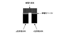
- FIG. 1 is a drawing schematically showing an example of the thermoelectric conversion element having the above-described structure.
- thermoelectric conversion element of the present invention has a composition formula: Mn 3-x1 M 1 x1 Si y1 Al z1 M 2 a1 (wherein M 1 , M 1 2 , x1, y1, z1, and a1 are the same as above, or a composition formula: Mn x2 M 3 y2 Si m2 Al n2 (wherein M 3 , x2, y2, m2, and n2 Is the same as above), and as a p-type thermoelectric conversion material, a composition formula: Mn m3 M 4 n3 Si p3 (wherein M 4 , m3, n3, and p3 are the same as above) N-type thermoelectric conversion using a conductive paste containing at least one noble metal selected from the group consisting of gold, platinum and palladium and a conductive metal consisting of silver as a bonding agent One end of material and p-type thermoelectric transformation One end of the replacement material is connected
- thermoelectric conversion element having such characteristics can effectively utilize the excellent thermoelectric power generation performance in the middle temperature range of the silicide used as the n-type thermoelectric conversion material and the p-type thermoelectric conversion material, and at the junction of the thermoelectric conversion material.
- Appropriate conductivity and sufficient bonding strength can be imparted, and even when power generation is repeated, the silver contained in the conductive paste does not diffuse into the thermoelectric conversion material, resulting in excellent thermoelectric conversion performance. The period can be maintained.
- N-type thermoelectric conversion material and p-type thermoelectric conversion material are usually formed into a sintered compact by the above-described method, and then can be processed into a shape suitable for manufacturing a thermoelectric conversion element, if necessary.
- a thermoelectric conversion material it can determine suitably with the magnitude
- a rectangular column having a length of 1 to 10 mm, a width of 1 to 10 mm, and a length of about 2 to 20 mm can be given.
- thermoelectric conversion material As a method for bonding the n-type thermoelectric conversion material and the p-type thermoelectric conversion material to the conductive substrate, for example, first, a conductive paste is applied to the surface of each thermoelectric conversion material to be bonded to the conductive substrate, The bonding surface of the conductive substrate is brought into contact with the substrate.
- the amount of the conductive paste applied is not particularly limited, and can be appropriately determined so that the thermoelectric conversion material can be connected with sufficient strength according to the specific blend composition of the paste.
- the paste is uniformly applied to the joint portion so that the thickness of the paste before solidification is about 10 ⁇ m to 500 ⁇ m and the thickness of the paste layer after solidification is about 1 ⁇ m to 200 ⁇ m.
- a conductive paste having the same composition may be used, but each of the p-type thermoelectric conversion material and the n-type thermoelectric conversion material. It is also possible to use conductive pastes having different compositions so as to optimize the bonding force and bonding electric resistance.
- the size of the conductive substrate there is no particular limitation on the size of the conductive substrate, and it is sufficient that there is a sufficient area for stably bonding the n-type thermoelectric conversion material and the p-type thermoelectric conversion material, and in particular, covers the entire bonding surface of the thermoelectric conversion material. It is preferable that the size be able to.
- the joining surface of the thermoelectric conversion material is preferably polished flat to increase the contact area with the conductive substrate. Furthermore, it is preferable to form a metal layer on the joint surface of the thermoelectric conversion material in order to strengthen the joint with the conductive paste and reduce the connection electrical resistance.
- a metal layer can be formed on the joint surface of the thermoelectric conversion material by an electroless plating method such as Ni—B plating.
- thermoelectric conversion material After bringing the joint surface of the conductive substrate into contact with the thermoelectric conversion material through the conductive paste, the solvent contained in the conductive paste is dried, and then the conductive paste is solidified, thereby forming the n-type thermoelectric conversion material.
- One end and one end of the p-type thermoelectric conversion material can be connected to the conductive substrate.
- organic components such as a solvent and an organic binder contained in the conductive paste are decomposed and removed, and then heated to a temperature equal to or higher than the softening temperature of the glass component contained in the paste, and the thermoelectric conversion material and the conductive substrate Can be made strong.
- the atmosphere during heating is not particularly limited, and can be any atmosphere such as air, vacuum, reducing gas atmosphere, inert gas atmosphere, and the like.
- heat treatment is preferably performed under an appropriate oxygen partial pressure.
- heat treatment can be performed in air at 300 to 500 ° C. for about 1 to 10 hours.
- the stage of the heat treatment at a temperature higher than the softening temperature of the glass component is preferably performed in a vacuum, reduced pressure, inert atmosphere, reducing atmosphere or the like to prevent oxidation of the thermoelectric conversion material.
- the heating temperature varies depending on the composition of the glass component, and for example, it is preferable to perform the heat treatment at 500 to 900 ° C. for about 1 to 10 hours.
- the pressure at this time is such that the thermoelectric conversion material and the conductive substrate are not damaged or deformed, and is, for example, about 1 to 20 MPa.
- thermoelectric conversion material when joining a thermoelectric conversion material to a conductive substrate using the above-described conductive paste, a sintered body containing a glass component in addition to a conductive metal is formed at the joint, thereby increasing the joint strength. Yes.
- thermoelectric power generation module of the present invention uses a plurality of the above-described thermoelectric conversion elements, an unjoined end of a p-type thermoelectric conversion material of one thermoelectric conversion element, and an n-type thermoelectric conversion of another thermoelectric conversion element.
- a plurality of thermoelectric conversion elements are connected in series by a method of connecting an unjoined end of a material onto a conductive substrate using a bonding agent.
- a conductive paste containing at least one kind of noble metal selected from the group consisting of gold, platinum and palladium and a conductive metal consisting of silver is used as the bonding agent.
- the conductive substrate used when manufacturing the thermoelectric conversion module is made of conductive metal, conductive ceramics, insulating ceramics with a metal coating, etc., as with the conductive substrate used when manufacturing the thermoelectric conversion elements.
- a substrate can be used.
- a substrate made of a conductive metal is preferable, and a sheet-like substrate made of silver is preferable from the viewpoint of price, electrical resistivity, thermal conductivity, and the like.
- thermoelectric conversion material of the thermoelectric conversion element can be the same as the bonding method used when the thermoelectric conversion element is manufactured.
- thermoelectric conversion elements used in one module is not limited and can be arbitrarily selected according to the required power.
- thermoelectric conversion module of the present invention when a conductive metal substrate, conductive ceramic substrate, or the like is used as the conductive substrate, an electrically insulating substrate can be further provided on the conductive substrate. As a result, the electrical insulation of the conductive substrate is maintained, and it is possible to prevent the thermoelectric elements from being short-circuited due to contact with a conductive portion such as a heat source, and to improve the thermal uniformity and mechanical strength. .
- the material of the electrically insulating substrate is not particularly limited.
- an insulating material having a high thermal conductivity that is chemically stable and does not react with a thermoelectric conversion material, a bonding agent or the like at a high temperature of about 1000 ° C. does not cause melting or breakage. It is preferable to use it.
- the temperature of the high temperature portion of the element can be brought close to the temperature of the high temperature heat source, and the generated voltage can be increased.
- oxide ceramics or nitride ceramics can be used as the electrically insulating substrate having such conditions. Specific examples include aluminum oxide, zirconium oxide, titanium oxide, magnesium oxide, silicon oxide, silicon nitride, and nitride. Aluminum, titanium nitride, silicon carbide, etc. can be mentioned.
- the shape of the electrically insulating substrate is not particularly limited, and can be determined according to the shape and size of the high temperature portion and the low temperature portion. Considering heat transfer in the high temperature part and heat dissipation in the low temperature part, the thickness of the electrically insulating substrate is preferably as thin as possible, more preferably about 0.1 to 5 mm.
- the electrically insulating substrate can be installed on both surfaces of the high temperature portion and the low temperature portion of the conductive substrate, or on either one of them depending on the usage pattern of the thermoelectric conversion module.
- the method for installing the electrically insulating substrate is not particularly limited.
- a material in which a conductive substrate is previously attached to an electrically insulating substrate can be used, and a thermoelectric conversion material can be bonded onto the conductive substrate. Further, after the thermoelectric conversion material is bonded to the conductive substrate, the electrically insulating substrate can be attached on the conductive substrate.
- the means for attaching the electrically insulating substrate is not particularly limited, and means capable of forming a bond having such a strength that does not cause peeling or the like during the manufacture and use of the thermoelectric conversion module can be employed. For example, a method of sintering a conductive substrate and an electrically insulating substrate by heat treatment, a method of bonding using a paste material, or the like can be applied.
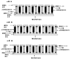
- FIG. 2 is a drawing showing a schematic structure of a (a) side surface, (b) front surface, and (c) back surface of a thermoelectric conversion module using 84 pairs of thermoelectric conversion elements.
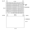
- FIG. 3 is a drawing showing a schematic structure of the upper surface and the back surface of the module.
- a plating layer is formed on each joint surface of the n-type thermoelectric conversion material and the p-type thermoelectric conversion material in order to improve the bondability with the conductive substrate.
- the electrically insulating substrate is installed only on one surface of the conductive substrate.
- thermoelectric power generation module of the present invention can generate a voltage by arranging one surface of the conductive substrate so as to be in contact with a high temperature heat source and arranging the other surface so as to be in contact with a low temperature part.
- the conductive substrate side on which the electrically insulating substrate is installed is arranged in the high temperature part, and the other surface is arranged in the low temperature part.
- the thermoelectric conversion module of this invention is not limited to such an installation method, Either one side can be arrange
- the module of FIG. 2 can be installed with the high temperature part side and the low temperature part side opposite.
- thermoelectric conversion material to be used is a metal material that can exhibit excellent thermoelectric conversion performance in the middle temperature range of room temperature to about 700 ° C., and air that has been difficult with conventionally known metal materials It is a material that can be used effectively even inside. Therefore, the thermoelectric conversion module of the present invention can be used for thermoelectric power generation using heat of about 400 ° C. to 600 ° C. from a factory, a garbage incinerator, a thermal power plant, a nuclear power plant, a micro turbine, or the like. Furthermore, it can also be used as a power source for automobiles where the temperature changes drastically.
- thermoelectric conversion element and thermoelectric conversion module of the present invention a specific silicide capable of exhibiting excellent performance in a middle temperature range from room temperature to about 700 ° C. is selected as a thermoelectric conversion material, and these thermoelectric conversion materials are bonded to a conductive substrate.
- a bonding agent to be used a paste containing at least one kind of noble metal selected from the group consisting of gold, platinum and palladium and silver as a conductive metal is used. Thereby, moderate electroconductivity can be provided to the junction part of a thermoelectric conversion material. Furthermore, even when power generation is repeated in the middle temperature range, good bonding strength can be maintained, and silver contained in the conductive paste does not diffuse into the thermoelectric conversion material, and good thermoelectric conversion performance is maintained for a long time. be able to.
- thermoelectric conversion module of the present invention it is possible to effectively use a heat source in the middle temperature range from room temperature to 700 ° C., and to perform efficient thermoelectric power generation for a long period of time.
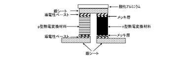
- thermoelectric conversion element shows typically an example of the thermoelectric conversion element of this invention. It is drawing which shows schematic structure of (a) side surface, (b) front surface, and (c) back surface of an example of the thermoelectric conversion module of this invention. It is drawing which shows the schematic structure of the upper surface of an example of the thermoelectric conversion module of this invention, and a back surface. It is the schematic of the thermoelectric conversion element which has distribute
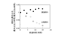
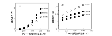
- FIG. 5A is a graph showing the maximum output of each thermoelectric conversion element of Example 1 and Comparative Example 1 with respect to the temperature of the plate-type electric furnace
- FIG. 6 is a graph showing the internal resistance of each thermoelectric conversion element of Example 1 and Comparative Example 1.
- FIG. 6 is a graph showing a time-dependent change in normalized maximum output for the thermoelectric conversion elements of Example 1 and Comparative Example 1.
- FIG. 7A is a graph showing the maximum output of each thermoelectric conversion module of Example 88 and Comparative Example 2 with respect to the temperature of the plate-type electric furnace, and FIG. It is a graph which shows the internal resistance of each thermoelectric conversion module of Example 88 and Comparative Example 2. It is a graph which shows the time-dependent change of the standardized maximum output about the thermoelectric conversion module of Example 88 and Comparative Example 2.
- FIG. 7A is a graph showing the maximum output of each thermoelectric conversion module of Example 88 and Comparative Example 2 with respect to the temperature of the plate-type electric furnace
- FIG. It is a graph which shows the internal resistance of each thermoelectric conversion module of Example 88 and Comparative Example 2.
- It is a graph which shows the time-dependent change of the standardized maximum output about the thermoelectric conversion module of Example 88 and Comparative Example 2.
- FIG. 7A is a graph showing the maximum
- Example 1 Production composition of p-type thermoelectric conversion material : A p-type thermoelectric conversion material represented by MnSi 1.75 was produced by the following method.
- the disc was placed in a carbon mold and subjected to hot press sintering at 920 ° C. for 7 hours under a uniaxial pressure of 11 MPa.
- the atmosphere was a vacuum.
- the hot-press sintered body was cut so as to have a prismatic shape with a cross section of 3.5 mm square and a length of 10 mm.
- Ni-B electroless plating was applied to the surface of this processed product. The thickness of the plating was about 5 ⁇ m.
- the plating on the surface other than the joint surface was removed by polishing with sandpaper to obtain a p-type thermoelectric conversion material used for the thermoelectric conversion module.
- the obtained alloy was pulverized with an agate mortar and pestle and sieved to obtain a powder having a particle size of 38 ⁇ m or less.
- the obtained powder was pressure-molded into a disc having a diameter of 40 mm and a thickness of about 5 mm. This is put in a carbon mold, applied with a direct current pulse current (pulse width 2.5 milliseconds, frequency 29 Hz) of about 2700 A, heated to 780 ° C., held at that temperature for 15 minutes, and energized. After ligation, the applied current and pressurization were stopped and allowed to cool naturally to obtain a sintered body.
- a direct current pulse current pulse width 2.5 milliseconds, frequency 29 Hz
- the sintered body was cut so as to be a prism having a cross section of 3.5 mm square and a length of 10 mm.
- Ni-B electroless plating was applied to the surface of this processed product.
- the thickness of the plating was about 5 ⁇ m.
- the plating on the surface other than the joint surface was removed by polishing with sandpaper to obtain an n-type thermoelectric conversion material used for the thermoelectric conversion module.
- the silver paste used is composed of 85% by weight of silver powder (particle size of about 0.1 to 5 ⁇ m), 1% by weight of bismuth borosilicate glass, 5% by weight of ethyl cellulose, 4% by weight of terpineol and 5% by weight of butyl carbitol acetate.
- the platinum paste is composed of 85% by weight of platinum powder (particle size of about 0.1 to 5 ⁇ m), 1% by weight of bismuth borosilicate glass, 5% by weight of ethyl cellulose, 4% by weight of terpineol and 5% by weight of butyl carbitol acetate. It is.
- thermoelectric conversion element A silver sheet having a width of 3.5 mm, a length of 7 mm and a thickness of 0.5 mm was prepared as a conductive substrate, and Ni—B plating of the above-described p-type thermoelectric conversion material and n-type thermoelectric conversion material was performed. A conductive paste containing silver and platinum powder is applied to a surface of 3.5 mm ⁇ 3.5 mm subjected to, and a silver sheet is connected to the p-type thermoelectric conversion material and the n-type thermoelectric conversion material thereon. It was put on.
- an aluminum oxide electrically insulating substrate having a width of 5 mm, a length of 8 mm, and a thickness of 0.5 mm was placed on the silver sheet so as to cover the entire silver sheet.
- the amount of paste applied was such that the thickness before solidification was about 100 ⁇ m.
- thermoelectric conversion element is inverted, and a conductive paste is similarly applied to the opposite cross section of the thermoelectric conversion material.
- Two silver sheets are placed on each of the n-type thermoelectric material and the p-type thermoelectric material, and the current is applied. The lead wire was taken out.
- thermoelectric conversion element After drying at about 100 ° C. for about 30 minutes, the organic components were thermally decomposed by heating in air at 350 ° C. for 5 hours. Next, this thermoelectric conversion element was heat-treated in vacuum at 600 ° C. with a uniaxial pressure of 6.5 MPa perpendicular to the bonding surface for 7 hours to solidify the conductive paste.
- thermoelectric conversion element which arranged the electrically insulating board
- the schematic diagram of the obtained thermoelectric conversion element is shown in FIG.
- thermoelectric conversion element was produced in the same manner as in Example 1 except that a commercially available silver paste (trade name: MH-108A, manufactured by Tanaka Kikinzoku Co., Ltd., silver content: 85% by weight) was used as the conductive paste.
- a commercially available silver paste (trade name: MH-108A, manufactured by Tanaka Kikinzoku Co., Ltd., silver content: 85% by weight) was used as the conductive paste.
- Test example 1 About each thermoelectric conversion element obtained in Example 1 and Comparative Example 1, the aluminum oxide substrate surface was heated in air at 100 to 600 ° C. using a plate-type electric furnace, and water at 20 ° C. was circulated at the opposite end. A temperature difference was generated by cooling with a copper jacket.
- the lead wire (silver sheet) placed on the low temperature side of the p-type thermoelectric conversion material and n-type thermoelectric conversion material is connected to the electronic load device, and the current-voltage characteristics are measured while changing the external load resistance. Resistance and output were obtained.
- the current-voltage characteristic is obtained as a straight line, but the absolute value of the slope (obtained as a negative value) of this straight line becomes the internal resistance of the thermoelectric conversion element.
- the output is a product of current and voltage, and is a quadratic function. The measured value was regressed to a quadratic function, and the maximum value of the quadratic curve obtained from the function was taken as the maximum output.
- the thermoelectric conversion element shows the maximum output when the external load resistance matches the internal resistance, but the maximum output was obtained at the point where they matched even when determined by the regression curve.
- FIG. 5A is a graph showing the maximum output of the thermoelectric conversion elements of Example 1 and Comparative Example 1 with respect to the temperature of the plate-type electric furnace
- FIG. 5 is a graph showing internal resistances of thermoelectric conversion elements of Example 1 and Comparative Example 1.
- the thermoelectric conversion element obtained in Example 1 had a lower internal resistance value, resulting in a higher maximum output.
- Example 1 by bonding the thermoelectric conversion material to the silver sheet using a paste containing silver and platinum, silver diffuses into the thermoelectric conversion material by heating during device fabrication and testing. Was suppressed and good thermoelectric power generation performance was demonstrated.
- Comparative Example 1 it is considered that the silver paste was used as the bonding agent, so that silver diffused into the thermoelectric conversion element during the heating, thereby reducing the thermoelectric power generation performance.
- FIG. 6 is a graph showing the change with time of the maximum output when the long-time test is performed with the temperature of the plate-type electric furnace set at 600 ° C.
- the vertical axis represents the maximum output value normalized by the maximum output measured immediately after the temperature of the plate-type electric furnace reaches 600 ° C.
- the maximum output was greatly decreased with time, but in Example 1, almost no change was observed. From these results, it was confirmed that durability in high-temperature air was improved by bonding the thermoelectric conversion material to the silver sheet using a paste containing silver and platinum.
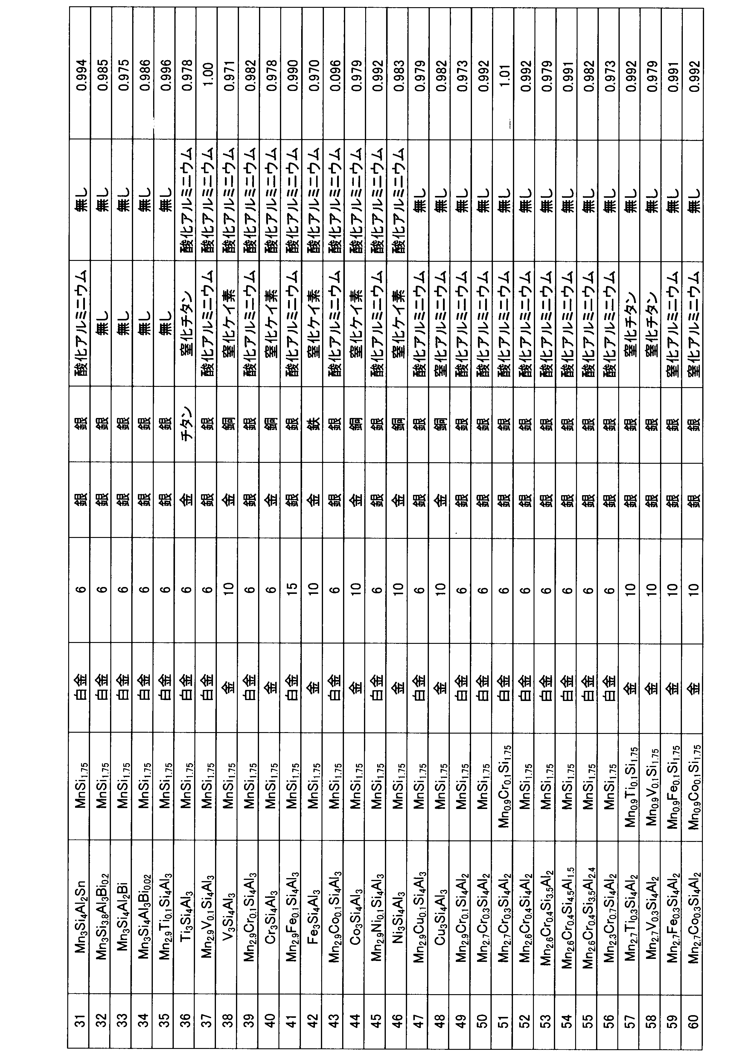
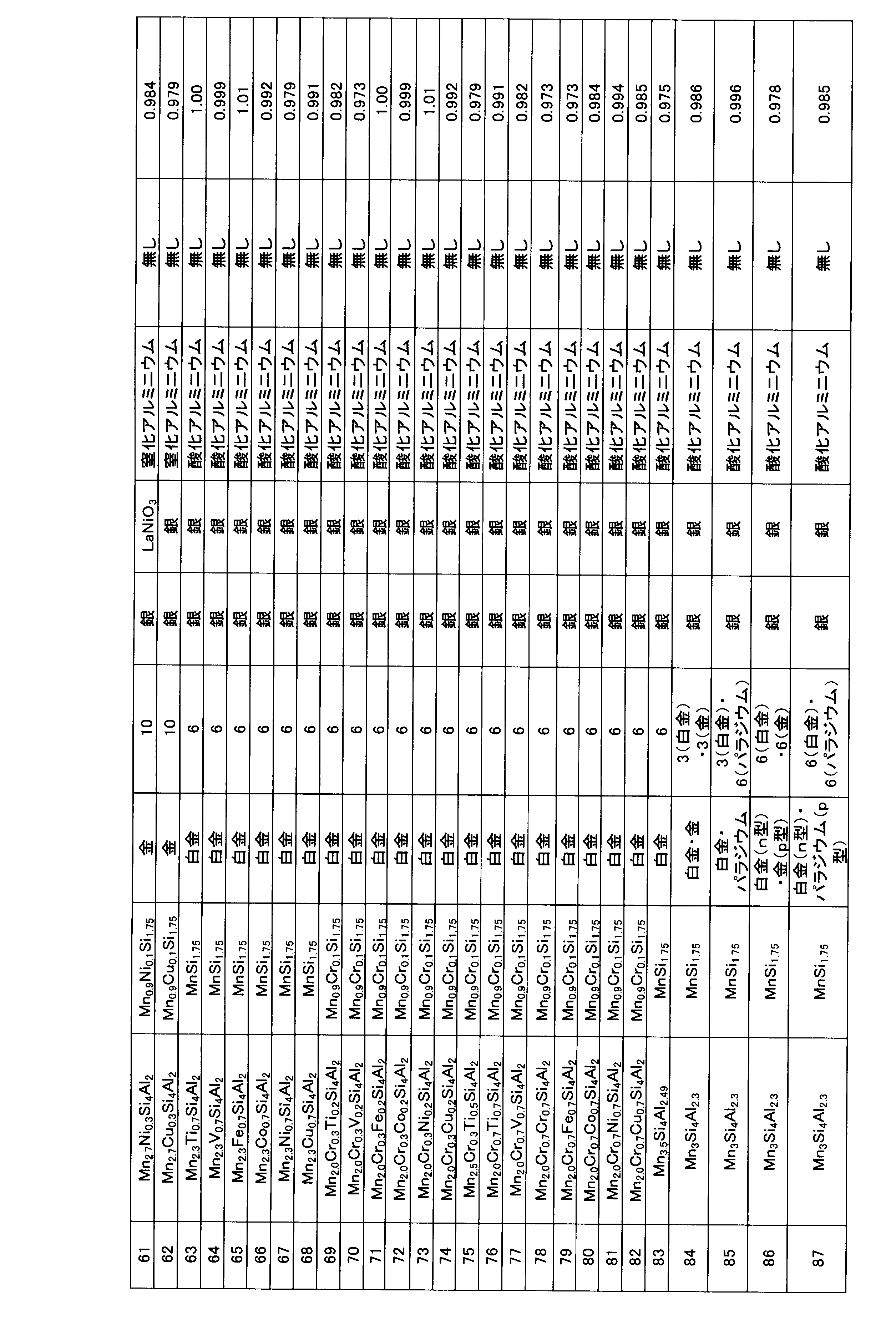
- Examples 2 to 87 Thermoelectric conversion elements were produced in the same manner as in Example 1 using the materials listed in Table 1 as the p-type thermoelectric conversion material, n-type thermoelectric conversion material, conductive substrate, and electrically insulating substrate.
- the installation method when installing the high temperature side insulating substrate and the low temperature side insulating substrate is the same as the installation method of the aluminum oxide substrate in the first embodiment.
- the mixed precious metal term describes the type of precious metal compounded in the conductive paste in addition to silver, and the precious metal compounding amount and silver amount of 100% by weight in the mixed silver term. It is described as weight%.
- the conductive substrates used on the high temperature side and the low temperature side are referred to as a high temperature side electrode material and a low temperature side electrode material, respectively.
- thermoelectric conversion elements obtained in Examples 2 to 87 the maximum output and the internal resistance differ depending on the composition of the thermoelectric conversion material, the material of the conductive substrate, the noble metal composition of the conductive paste, and the like.
- the change in the maximum output was smaller than that of the thermoelectric conversion element obtained in Comparative Example 1, and was almost the same as that of Example 1. From this result, it was confirmed that the durability in high-temperature air was improved by bonding the thermoelectric conversion material to the silver sheet using a paste containing silver and platinum.
- thermoelectric conversion module On a 3 cm square and 0.8 mm thick aluminum oxide substrate, seven silver sheets with a width of 7 mm, a length of 7 mm, and a thickness of 0.5 mm, and appropriate intervals to connect thermoelectric conversion materials Arranged by.
- thermoelectric conversion material As the p-type thermoelectric conversion material and the n-type thermoelectric conversion material, a prismatic material having a cross section of 3.5 mm ⁇ 7 mm and a length of 10 mm, respectively, produced by the same method as in Example 1 was used.
- thermoelectric conversion materials The same conductive paste as that used in Example 1 was applied to both sides of 3.5 mm ⁇ 7 mm of these thermoelectric conversion materials, and p-type thermoelectric conversion materials and n were placed on the silver sheets arranged on the aluminum oxide substrate.
- the p-type thermoelectric conversion material was placed as a whole, and 14 p-type thermoelectric conversion materials and n-type thermoelectric conversion materials were alternately arranged.
- the amount of paste applied was such that the thickness before solidification was about 100 ⁇ m.
- thermoelectric conversion module precursor comprised by 14 pairs of thermoelectric conversion elements was manufactured.
- the precursor was dried at about 100 ° C. for about 30 minutes and then heated in air at 350 ° C. for 5 hours to thermally decompose the organic components.
- heat treatment was performed at 600 ° C. for 7 hours in a vacuum to solidify the conductive paste.
- the thickness of the paste layer after solidification was about 20 ⁇ m.
- the aluminum oxide substrate was burned with the silver sheet during the heat treatment, and a thermoelectric conversion module in which 14 pairs of thermoelectric conversion elements were connected in series and an electrically insulating substrate was disposed on one side was obtained.
- Example 89 As the p-type thermoelectric conversion material and the n-type thermoelectric conversion material, prismatic materials having a cross section of 3.5 mm ⁇ 7 mm and a length of 10 mm, respectively, produced by the same method as in Example 1 were used. However, both the p-type thermoelectric conversion material and the n-type thermoelectric conversion material were used without forming a Ni—B electroless plating film on the surface.
- thermoelectric conversion module in which 14 pairs of thermoelectric conversion elements are connected in series and an electrically insulating substrate is disposed on one side in the same manner as in Example 88. was made.
- thermoelectric conversion elements As a conductive paste, 14 pairs of thermoelectric conversion elements were prepared in the same manner as in Example 88, except that a commercially available silver paste (trade name: MH-108A, manufactured by Tanaka Kikinzoku Co., Ltd., silver content: 85 wt%) was used. A thermoelectric conversion module connected in series and having an electrically insulating substrate disposed on one side was produced.
- Test example 2 For each of the thermoelectric conversion modules of Example 88, Example 89, and Comparative Example 2 obtained by the above method, the aluminum oxide substrate portion was heated to 100 to 600 ° C. in air using a plate-type electric furnace, The surface was cooled with a copper jacket in which water at 20 ° C. was circulated to produce a temperature difference.
- thermoelectric conversion module Connect the lead wires arranged on the low temperature side of the p-type thermoelectric conversion material and the low temperature side of the n-type thermoelectric conversion material to the electronic load device, measure the current-voltage characteristics while changing the external load resistance, Got the output.
- the current-voltage characteristic is obtained as a straight line
- the absolute value of the slope (obtained as a negative value) of this straight line is the internal resistance of the thermoelectric conversion module.
- the output is a product of current and voltage and is a quadratic function. The measured value was regressed to a quadratic function, and the maximum value of the quadratic curve obtained from the function was taken as the maximum output.
- the thermoelectric conversion module shows the maximum output when the external load resistance coincides with the internal resistance, but the maximum output was obtained at the point where they matched even when determined by the regression curve.
- FIG. 7A is a graph showing the maximum output of each thermoelectric conversion module of Example 88, Example 89 and Comparative Example 2 with respect to the temperature of the plate-type electric furnace
- FIG. 7B is a plate-type electric furnace. It is a graph which shows the internal resistance of each thermoelectric conversion module of Example 88, Example 89, and the comparative example 2 with respect to this temperature.
- thermoelectric conversion modules obtained in Example 88 and Example 89 had lower internal resistance values, resulting in higher maximum output.
- the thermoelectric conversion module of Example 88 on which the nickel plating film was formed had a low internal resistance, but the thermoelectric conversion module of Example 89 also had a sufficiently low internal resistance value.
- the thermoelectric conversion material was bonded to the silver sheet using a paste containing silver and platinum, so that the silver was thermoelectrically converted by heating during the production of the module and during the test. Diffusion into the material was suppressed and good thermoelectric power generation performance was demonstrated.
- Comparative Example 2 it is considered that the silver paste was used as the bonding agent, so that silver diffused into the thermoelectric conversion element during heating, thereby reducing the thermoelectric power generation performance.
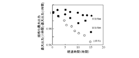
- FIG. 8 shows the change over time in the maximum output when the temperature of the plate-type electric furnace is 600 ° C. and the test is performed for a long time.
- the vertical axis represents the maximum output value normalized by the maximum output measured immediately after the temperature of the plate-type electric furnace reaches 600 ° C.
- Example 88 a large decrease in the maximum output was observed, but almost no change was observed in Example 88.
- Example 89 the decrease in the maximum output was small as compared with Comparative Example 2. From these results, it was confirmed that durability in high-temperature air was improved by bonding the thermoelectric conversion material to the silver sheet using a paste containing silver and platinum.
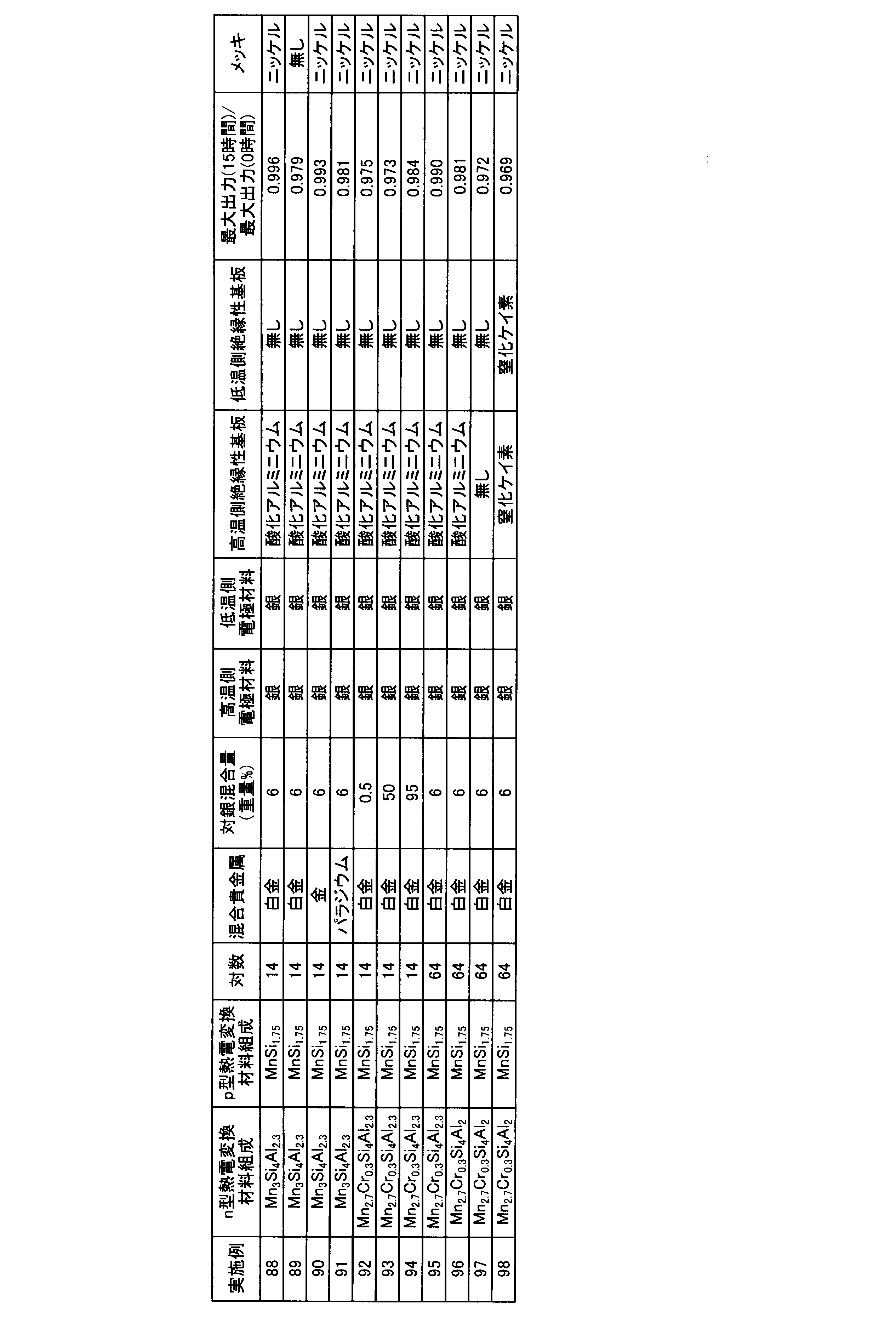
- thermoelectric conversion module was produced in the same manner as in Example 88 using the materials shown in Table 2 as the p-type thermoelectric conversion material, the n-type thermoelectric conversion material, the conductive substrate, and the electrically insulating substrate.
- the method for installing the high temperature side insulating substrate and the low temperature side insulating substrate is the same as the method for installing the aluminum oxide substrate in Example 88.
- the mixed precious metal term describes the type of precious metal blended in the conductive paste in addition to silver, and the mixed precious metal term shows the precious metal blending amount and the silver amount of 100% by weight. It is described as weight%.
- the conductive substrates used on the high temperature side and the low temperature side are referred to as a high temperature side electrode material and a low temperature side electrode material, respectively.
- thermoelectric conversion modules of Examples 90 to 98 the maximum output and internal resistance differ depending on the composition of the thermoelectric conversion material, the material of the conductive substrate, the precious metal composition of the conductive paste, etc., but the maximum output for all thermoelectric conversion modules The change was smaller than that of the thermoelectric conversion module obtained in Comparative Example 2, and almost the same as that of Example 88. From this result, it was confirmed that the durability in high-temperature air was improved by bonding the thermoelectric conversion material to the silver sheet using a paste containing silver and platinum.
Landscapes
- Chemical & Material Sciences (AREA)
- Engineering & Computer Science (AREA)
- Mechanical Engineering (AREA)
- Organic Chemistry (AREA)
- Inorganic Chemistry (AREA)
- Metallurgy (AREA)
- Materials Engineering (AREA)
- Physics & Mathematics (AREA)
- Dispersion Chemistry (AREA)
- Spectroscopy & Molecular Physics (AREA)
- Manufacturing & Machinery (AREA)
- Conductive Materials (AREA)
- Silicon Compounds (AREA)
- Powder Metallurgy (AREA)
- Ceramic Products (AREA)
Abstract
Description
項1. n型熱電変換材料の一端とp型熱電変換材料との一端を、それぞれ接合剤を用いて導電性基板に接続してなる熱電変換素子であって、
(1)n型熱電変換材料が、下記(a)項又は(b)項に記載したケイ化物であり、
(a)組成式:Mn3-x1M1 x1Siy1Alz1M2 a1 (式中、M1は、Ti、V、Cr、Fe、Co、Ni、及びCuからなる群から選ばれる少なくとも一種の元素であり、M2は、B、P、Ga、Ge、Sn、及びBiからなる群から選ばれる少なくとも一種の元素であり、0≦x1≦3.0、3.5≦y1≦4.5、2.0≦z1≦3.5、0≦a1≦1である)で表され、25℃以上の温度で負のゼーベック係数を有するケイ化物、
(b)組成式:Mnx2M3 y2Sim2Aln2 (式中、M3は、Ti、V、Cr、Fe、Co、Ni、及びCuからなる群から選ばれる少なくとも一種の元素であり、2.0≦x2≦3.5、0≦y2≦1.4であって、2.5≦x2+y2≦3.5であり、3.5≦m2≦4.5、1.5≦n2≦2.49である)で表され、25℃以上の温度で負のゼーベック係数を有するケイ化物、
(2)p型熱電変換材料が、組成式:Mnm3M4 n3Sip3(式中、M4はTi、V、Cr、Fe、Co、Ni及びCuからなる群から選ばれる少なくとも一種の元素であり0.8≦m3≦1.2、0≦n3≦0.4、1.5≦p3≦2.0である)で表され、25℃以上の温度で正のゼーベック係数を有するケイ化物であり、
(3)接合剤が、金、白金及びパラジウムからなる群から選ばれた少なくとも一種の貴金属並びに銀からなる導電性金属を含む導電性ペーストである、熱電変換素子。
項2. 導電性ペースト中の金、白金及びパラジウムからなる群から選ばれた少なくとも一種の貴金属の総量が、銀100重量部に対して、0.5~95重量部である、上記項1に記載の熱電変換素子。
項3. 導電性ペーストが、更に、ガラス粉末成分、樹脂成分、及び溶剤成分を含有する、上記項1又は2に記載の熱電変換素子。
項4. 導電性基板が、シート状導電性金属、導電性セラミックス、又は導電性金属被覆を形成した絶縁性セラミックスである、上記項1~3のいずれかに記載の熱電変換素子。
項5. 導電性基板が、厚さ0.05~3mmの銀製シートである、上記項4に記載の熱電変換素子。
項6. 上記項1~5のいずれかに記載の熱電変換素子を複数個用い、一つの熱電変換素子のp型熱電変換材料の未接合の端部と、他の熱電変換素子のn型熱電変換材料の未接合の端部を、接合剤を用いて導電性基板上に接続する方法で、複数の熱電変換素子を直列に接続した熱電変換モジュールであって、接合剤が、金、白金及びパラジウムからなる群から選ばれた少なくとも一種の貴金属と銀とからなる導電性金属を含む導電性ペーストであることを特徴とする、熱電変換モジュール。
項7. 導電性ペースト中の金、白金及びパラジウムからなる群から選ばれた少なくとも一種の貴金属の総量が、銀100重量部に対して、0.5~95重量部である、上記項6に記載の熱電変換モジュール。
項8. 導電性ペーストが、更に、ガラス粉末成分、樹脂成分、及び溶剤成分を含有する、上記項6又は7に記載の熱電変換モジュール。
項9. 導電性基板が、シート状導電性金属、導電性セラミックス、又は導電性金属被覆を形成した絶縁性セラミックスである、上記項6~8のいずれかに記載の熱電変換モジュール。
項10. 導電性基板が、厚さ0.05~3mmの銀製シートである、上記項9に記載の熱電変換モジュール。
項11. 上記項6~10のいずれかの熱電変換モジュールの両面又は片面の導電性基板上に電気絶縁性基板が配置されている、熱電変換モジュール。
項12. 電気絶縁性基板が、酸化物セラミックス又は窒化物セラミックスである、上記項11に記載の熱電変換モジュール。
項13. 上記項6~11のいずれかに記載の熱電変換モジュールの一方の導電性基板面側を高温部に配置し、他方の導電性基板面側を低温部に配置する工程を備えた、熱電発電方法。
(1)n型熱電変換材料
本発明では、n型熱電変換材料として、下記(a)又は(b)項に記載したケイ化物を用いる。
(a)組成式:Mn3-x1M1 x1Siy1Alz1M2 a1 (式中、M1は、Ti、V、Cr、Fe、Co、Ni、及びCuからなる群から選ばれる少なくとも一種の元素であり、M2は、B、P、Ga、Ge、Sn、及びBiからなる群から選ばれる少なくとも一種の元素であり、0≦x1≦3.0、特に0.1≦x1≦2.9;3.5≦y1≦4.5、特に3.7≦y1≦4.3;2.0≦z1≦3.5、特に2.5≦z1≦3.5、さらには2.7≦z1≦3.3;0≦a1≦1、特に0.01≦a1≦0.99である)で表され、25℃以上の温度で負のゼーベック係数を有するケイ化物。
(b)組成式:Mnx2M3 y2Sim2Aln2 (式中、M3は、Ti、V、Cr、Fe、Co、Ni、及びCuからなる群から選ばれる少なくとも一種の元素であり、2.0≦x2≦3.5、特に2.2≦x2≦3.3;0≦y2≦1.4、特に0.1≦y2≦1.3であって;2.5≦x2+y2≦3.5、特に2.7≦x2+y2≦3.3であり;3.5≦m2≦4.5、特に3.7≦m2≦4.3;1.5≦n2≦2.49、特に1.6≦n2≦2.4である)で表され、25℃以上の温度で負のゼーベック係数を有するケイ化物。
本発明では、p型熱電変換材料としては、組成式:Mnm3M4 n3Sip3(式中、M4はTi、V、Cr、Fe、Co、Ni及びCuからなる群から選ばれる少なくとも一種の元素であり、0.8≦m3≦1.2、特に0.9≦m3≦1.1;0≦n3≦0.4、特に0.1≦n3≦0.3;1.5≦p3≦2.0、特に1.5≦p3≦1.9、特に1.6≦p3≦1.8である)で表され、25℃以上の温度で正のゼーベック係数を有するケイ化物を用いる。この材料は、一般的に、Mnが形成する四角柱内の空隙をらせん構造のSiが占有するチムニー・ラダー型構造を有する合金である。
上記したn型熱電変換材料及びp型熱電変換材料は、いずれも、熱電変換材料として用いる場合には、通常、目的とする用途に応じた形状の焼結成形体として用いられる。焼結成形体を作製するには、まず、上記した組成式で表されるケイ化物を粉砕して粉末とした後、目的とする形状に成形する。粉砕の程度(粒径、粒度分布、粒子形状等)については特に限定は無いが、できるだけ微細な粉末とすることによって、次の工程である焼結が容易となる。例えば、ボールミル等の粉砕手段を適用することによって、ケイ化物の粉砕と混合とを同時に行うことができる。粉砕物を焼結させる方法についても特に限定はない。例えば、通常の電気加熱炉、ガス加熱炉等の任意の加熱手段を適用できる。加熱温度、加熱時間についても特に限定はなく、十分な強度の焼結体が形成されるようにこれらの条件を適宜設定することができる。特に、導電性を有する型に粉砕物を充填し、加圧成形した後、該型に直流パルス電流を通電して焼結させる通電焼結法を適用する場合には、短時間で緻密な焼結体を得ることができる。通電焼結の条件についても特に制限はなく、例えば、必要に応じて、5~30MPa程度の圧力で加圧した状態で、600~850℃程度で5~30分程度加熱することができる。加熱時の雰囲気については、原料の酸化を避けるために、窒素、アルゴン等の不活性ガス雰囲気、還元性雰囲気、減圧雰囲気等の非酸化性雰囲気とすることが好ましい。また一軸加圧下で電気炉により焼成するホットプレス焼結法も利用できる。ホットプレス焼結の条件についても特に制限はない。5~50MPa程度の圧力で加圧した状態で、700~950℃程度で1~20時間程度加熱することができる。加熱時の雰囲気については、原料の酸化を避けるために、窒素、アルゴン等の不活性ガス雰囲気、還元性雰囲気、減圧雰囲気等の非酸化性雰囲気とすることが好ましい。
本発明では、上記したケイ化物からなるn型熱電変換材料とp型熱電変換材料とを導電性基板に接合するための接合剤として、金、白金及びパラジウムからなる群から選ばれた少なくとも一種の貴金属並びに銀からなる導電性金属を含む導電性ペーストを用いる。
上記したn型熱電変換材料の一端とp型熱電変換材料との一端を結合する導電性基板としては、上記した熱電変換材料を接続可能であって、十分な電気伝導性を有する材料が挙げられる。例えば、シート状の導電性金属からなる基板、導電性セラミックス基板、導電性金属被覆を形成した絶縁性セラミックス基板等を用いることができる。
本発明の熱電変換素子は、n型熱電変換材料の一端とp型熱電変換材料との一端を、それぞれ、導電性ペーストを用いて導電性基板に接続したものである。
本発明の熱電発電モジュールは、上記した熱電変換素子を複数個用い、一つの熱電変換素子のp型熱電変換材料の未接合の端部と、他の熱電変換素子のn型熱電変換材料の未接合の端部とを、接合剤を用いて導電性基板上に接続する方法で、複数の熱電変換素子を直列に接続したものである。本発明の熱電変換モジュールにおいて、接合剤として、上記した金、白金及びパラジウムからなる群から選ばれた少なくとも一種の貴金属並びに銀からなる導電性金属を含む導電性ペーストを用いる。
p型熱電変換材料の製造
組成式:MnSi1.75で表されるp型熱電変換材料を下記の方法で製造した。
マンガン(Mn)、シリコン(Si)及びアルミニウム(Al)をの小片を用い、Mn:Si:Al(元素比)=3.0:4.0:2.3となるように秤量後、アーク熔解法により約35kPaの減圧アルゴン雰囲気中で熔融させ、融液を十分に混合した後、室温まで冷却して、上記した原料成分からなる熔解固化物を得た。
市販の銀ペースト(商標名:MH-108A 、田中貴金属社製、銀含有量85重量%)100重量部に対して白金ペースト(商標名:TR-7905 田中貴金属社製、白金含有量85重量%)を6重量部秤取り、銀ペーストと白金ペーストとを十分に混練して、導電性ペーストを調製した。使用した銀ペーストは、銀粉末(粒径0.1~5μm程度)85重量%、ホウケイ酸ビスマスガラス1重量%、エチルセルロース5重量%、テルピネオール4重量%及びブチルカルビトールアセテート5重量%からなるものであり、白金ペーストは白金粉末(粒径0.1~5μm程度)85重量%、ホウケイ酸ビスマスガラス1重量%、エチルセルロース5重量%、テルピネオール4重量%及びブチルカルビトールアセテート5重量%からなるものである。
導電性基板として、幅3.5mm、長さ7mm、厚さ0.5mmの銀シートを準備し、上記したp型熱電変換材料とn型熱電変換材料とのNi-Bメッキを施した3.5mm×3.5mmの面に、銀と白金粉末とを含む導電性ペーストを塗布し、その上に銀シートをp型熱電変換材料とn型熱電変換材料とを接続するように載せた。さらに、銀シートの上に幅5mm、長さ8mm、及び厚さ0.5mmの酸化アルミニウムの電気絶縁性基板を銀シート全体を覆うように載せた。ペーストの塗布量は固化前の厚さが、約100μmとなるようにした。
導電性ペーストとして、市販の銀ペースト(商標名:MH-108A 、田中貴金属社製、銀含有量85重量%)を用いること以外は、実施例1と同様にして、熱電変換素子を作製した。
実施例1及び比較例1で得られた各熱電変換素子について、プレート型の電気炉を用いて酸化アルミニウム基板面を空気中で100~600℃で加熱し、反対端を20℃の水が循環している銅製ジャケットで冷却して温度差を生じさせた。
p型熱電変換材料、n型熱電変換材料、導電性基板、及び電気絶縁性基板として、表1に記載した材料を用いて、実施例1と同様にして熱電変換素子を作製した。高温側絶縁性基板及び低温側絶縁性基板を設置する場合の設置方法は、実施例1における酸化アルミニウム基板の設置方法と同様である。

熱電変換モジュールの作製
3cm角及び厚さ0.8mmの酸化アルミニウム基板上に、幅7mm、長さ7mm、及び厚さ0.5mmの銀シートを7枚、熱電変換材料を接続できるよう適当な間隔で配列した。
p型熱電変換材料及びn型熱電変換材料は、それぞれ実施例1と同様の方法で作製した断面が3.5mmx7mm、及び長さが10mmの角柱状の材料を用いた。但し、p型熱電変換材料及びn型熱電変換材料は、いずれも表面にNi-B無電解メッキ皮膜を形成することなく用いた。
導電性ペーストとして、市販の銀ペースト(商標名:MH-108A 、田中貴金属社製、銀含有量85重量%)を用いること以外は、実施例88と同様にして、14対の熱電変換素子を直列に接続し、片面に電気絶縁基板を配置した熱電変換モジュールを作製した。
上記した方法で得られた実施例88、実施例89及び比較例2の各熱電変換モジュールについて、プレート型の電気炉を用いて酸化アルミニウム基板部を空気中で100~600℃に加熱し、反対面を20℃の水が循環している銅製ジャケットで冷却して温度差を生じさせた。
p型熱電変換材料、n型熱電変換材料、導電性基板、及び電気絶縁性基板として、表2に記載した材料を用いて、実施例88と同様にして熱電変換モジュールを作製した。高温側絶縁性基板と低温側絶縁性基板とを設置する場合の設置方法は、実施例88における酸化アルミニウム基板の設置方法と同様である。
Claims (13)
- n型熱電変換材料の一端とp型熱電変換材料との一端を、それぞれ接合剤を用いて導電性基板に接続してなる熱電変換素子であって、
(1)n型熱電変換材料が、下記(a)項又は(b)項に記載したケイ化物であり、
(a)組成式:Mn3-x1M1 x1Siy1Alz1M2 a1 (式中、M1は、Ti、V、Cr、Fe、Co、Ni、及びCuからなる群から選ばれる少なくとも一種の元素であり、M2は、B、P、Ga、Ge、Sn、及びBiからなる群から選ばれる少なくとも一種の元素であり、0≦x1≦3.0、3.5≦y1≦4.5、2.0≦z1≦3.5、0≦a1≦1である)で表され、25℃以上の温度で負のゼーベック係数を有するケイ化物、
(b)組成式:Mnx2M3 y2Sim2Aln2 (式中、M3は、Ti、V、Cr、Fe、Co、Ni、及びCuからなる群から選ばれる少なくとも一種の元素であり、2.0≦x2≦3.5、0≦y2≦1.4であって、2.5≦x2+y2≦3.5であり、3.5≦m2≦4.5、1.5≦n2≦2.49である)で表され、25℃以上の温度で負のゼーベック係数を有するケイ化物、
(2)p型熱電変換材料が、組成式:Mnm3M4 n3Sip3(式中、M4はTi、V、Cr、Fe、Co、Ni及びCuからなる群から選ばれる少なくとも一種の元素であり0.8≦m3≦1.2、0≦n3≦0.4、1.5≦p3≦2.0である)で表され、25℃以上の温度で正のゼーベック係数を有するケイ化物であり、
(3)接合剤が、金、白金及びパラジウムからなる群から選ばれた少なくとも一種の貴金属並びに銀からなる導電性金属を含む導電性ペーストである、熱電変換素子。 - 導電性ペースト中の金、白金及びパラジウムからなる群から選ばれた少なくとも一種の貴金属の総量が、銀100重量部に対して、0.5~95重量部である、請求項1に記載の熱電変換素子。
- 導電性ペーストが、更に、ガラス粉末成分、樹脂成分、及び溶剤成分を含有する、請求項1又は2に記載の熱電変換素子。
- 導電性基板が、シート状導電性金属、導電性セラミックス、又は導電性金属被覆を形成した絶縁性セラミックスである、請求項1~3のいずれかに記載の熱電変換素子。
- 導電性基板が、厚さ0.05~3mmの銀製シートである、請求項4に記載の熱電変換素子。
- 請求項1~5のいずれかに記載の熱電変換素子を複数個用い、一つの熱電変換素子のp型熱電変換材料の未接合の端部と、他の熱電変換素子のn型熱電変換材料の未接合の端部を、接合剤を用いて導電性基板上に接続する方法で、複数の熱電変換素子を直列に接続した熱電変換モジュールであって、接合剤が、金、白金及びパラジウムからなる群から選ばれた少なくとも一種の貴金属並びに銀からなる導電性金属を含む導電性ペーストであることを特徴とする、熱電変換モジュール。
- 導電性ペースト中の金、白金及びパラジウムからなる群から選ばれた少なくとも一種の貴金属の総量が、銀100重量部に対して、0.5~95重量部である、請求項6に記載の熱電変換モジュール。
- 導電性ペーストが、更に、ガラス粉末成分、樹脂成分、及び溶剤成分を含有する、請求項6又は7に記載の熱電変換モジュール。
- 導電性基板が、シート状導電性金属、導電性セラミックス、又は導電性金属被覆を形成した絶縁性セラミックスである、請求項6~8のいずれかに記載の熱電変換モジュール。
- 導電性基板が、厚さ0.05~3mmの銀製シートである、請求項9に記載の熱電変換モジュール。
- 請求項6~10のいずれかの熱電変換モジュールの両面又は片面の導電性基板上に電気絶縁性基板が配置されている、熱電変換モジュール。
- 電気絶縁性基板が、酸化物セラミックス又は窒化物セラミックスである、請求項11に記載の熱電変換モジュール。
- 請求項6~11のいずれかに記載の熱電変換モジュールの一方の導電性基板面側を高温部に配置し、他方の導電性基板面側を低温部に配置する工程を備えた、熱電発電方法。
Priority Applications (4)
| Application Number | Priority Date | Filing Date | Title |
|---|---|---|---|
| JP2016519290A JP6249382B2 (ja) | 2014-05-16 | 2015-05-13 | 熱電変換素子及び熱電変換モジュール |
| US15/311,658 US20170125658A1 (en) | 2014-05-16 | 2015-05-13 | Thermoelectric Conversion Element and Thermoelectric Conversion Module |
| CN201580023910.4A CN106463600A (zh) | 2014-05-16 | 2015-05-13 | 热电转换元件及热电转换模块 |
| EP15792483.8A EP3144986A4 (en) | 2014-05-16 | 2015-05-13 | Thermoelectric conversion element and thermoelectric conversion module |
Applications Claiming Priority (2)
| Application Number | Priority Date | Filing Date | Title |
|---|---|---|---|
| JP2014-102234 | 2014-05-16 | ||
| JP2014102234 | 2014-05-16 |
Publications (1)
| Publication Number | Publication Date |
|---|---|
| WO2015174462A1 true WO2015174462A1 (ja) | 2015-11-19 |
Family
ID=54479999
Family Applications (1)
| Application Number | Title | Priority Date | Filing Date |
|---|---|---|---|
| PCT/JP2015/063791 Ceased WO2015174462A1 (ja) | 2014-05-16 | 2015-05-13 | 熱電変換素子及び熱電変換モジュール |
Country Status (5)
| Country | Link |
|---|---|
| US (1) | US20170125658A1 (ja) |
| EP (1) | EP3144986A4 (ja) |
| JP (1) | JP6249382B2 (ja) |
| CN (1) | CN106463600A (ja) |
| WO (1) | WO2015174462A1 (ja) |
Cited By (7)
| Publication number | Priority date | Publication date | Assignee | Title |
|---|---|---|---|---|
| JP2017191816A (ja) * | 2016-04-11 | 2017-10-19 | 学校法人東京理科大学 | 導電膜付き柱状インゴット基板及びその製造方法、シリサイド系熱電変換素子及びその製造方法、熱電変換モジュール、並びにシリサイド系熱電変換素子の電極層形成用組成物 |
| WO2019004429A1 (ja) * | 2017-06-29 | 2019-01-03 | 三菱マテリアル株式会社 | 熱電変換モジュール、及び、熱電変換モジュールの製造方法 |
| JP2019012829A (ja) * | 2017-06-29 | 2019-01-24 | 三菱マテリアル株式会社 | 熱電変換モジュール、及び、熱電変換モジュールの製造方法 |
| JP2019067987A (ja) * | 2017-10-04 | 2019-04-25 | 直江津電子工業株式会社 | 熱電変換素子及びその製造方法並びに熱電変換モジュール |
| WO2021153550A1 (ja) | 2020-01-31 | 2021-08-05 | 国立研究開発法人産業技術総合研究所 | 熱電変換モジュール |
| JP2022119182A (ja) * | 2021-02-03 | 2022-08-16 | 三菱マテリアル株式会社 | 熱電変換モジュール、および、熱電変換モジュールの製造方法 |
| JP2022144073A (ja) * | 2021-03-18 | 2022-10-03 | 国立研究開発法人産業技術総合研究所 | 熱電変換層を有する積層体とその製造方法、及び発電モジュール |
Families Citing this family (8)
| Publication number | Priority date | Publication date | Assignee | Title |
|---|---|---|---|---|
| WO2018028772A1 (en) * | 2016-08-10 | 2018-02-15 | Politecnico Di Milano | Active material and electric power generator containing it |
| CN106907049A (zh) * | 2017-04-19 | 2017-06-30 | 南华大学 | 一种利用余热发电的烟气净化烟囱 |
| US20180366354A1 (en) | 2017-06-19 | 2018-12-20 | Applied Materials, Inc. | In-situ semiconductor processing chamber temperature apparatus |
| IT201800002541A1 (it) * | 2018-02-09 | 2019-08-09 | Termo Ind Sa | Materiale attivo e generatore di potenza elettrica contenente lo stesso |
| IT201800002547A1 (it) * | 2018-02-09 | 2019-08-09 | Termo Ind Sa | Batteria semi-solida con capacita’ di ricarica |
| CN114258596B (zh) * | 2019-09-05 | 2026-03-24 | 株式会社博迈立铖 | 热电转换模块的制造方法 |
| CN112621116B (zh) * | 2020-12-07 | 2022-07-01 | 哈尔滨工业大学 | 一种用于方钴矿热电材料与Cu基电极的低温纳米连接方法 |
| CN117245233B (zh) * | 2023-10-18 | 2024-07-26 | 江苏智疆航空科技发展有限公司 | 一种负压稳固式特种陶瓷基板激光切割装置及其切割方法 |
Citations (6)
| Publication number | Priority date | Publication date | Assignee | Title |
|---|---|---|---|---|
| JPH04246106A (ja) * | 1991-01-26 | 1992-09-02 | Tanaka Kikinzoku Kogyo Kk | 銀−パラジウム−白金複合微粉末とその製造方法 |
| JPH0580902A (ja) * | 1991-09-18 | 1993-04-02 | Canon Inc | 情報処理装置 |
| JP2011198831A (ja) * | 2010-03-17 | 2011-10-06 | Fujitsu Ltd | 熱電変換モジュールおよび複合熱電変換素子 |
| JP2013042862A (ja) * | 2011-08-23 | 2013-03-04 | National Institute Of Advanced Industrial Science & Technology | 発電機能を有する調理器具 |
| JP2013229457A (ja) * | 2012-04-26 | 2013-11-07 | Mitsubishi Electric Corp | 半導体装置および半導体装置の製造方法 |
| JP2014049737A (ja) * | 2012-09-04 | 2014-03-17 | National Institute Of Advanced Industrial & Technology | n型熱電変換性能を有する金属材料 |
Family Cites Families (9)
| Publication number | Priority date | Publication date | Assignee | Title |
|---|---|---|---|---|
| JPH04246105A (ja) * | 1991-01-26 | 1992-09-02 | Tanaka Kikinzoku Kogyo Kk | 銀−白金複合微粉末とその製造方法 |
| JPH0533547U (ja) * | 1991-10-04 | 1993-04-30 | 三洋電機株式会社 | 光起電力装置 |
| JPH07153866A (ja) * | 1993-10-04 | 1995-06-16 | Tokuyama Corp | セラミック回路基板 |
| JPH09186368A (ja) * | 1995-10-31 | 1997-07-15 | Technova:Kk | 厚膜熱電素子 |
| DE602004027152D1 (de) * | 2003-10-08 | 2010-06-24 | Nat Inst Of Advanced Ind Scien | Ischen umwandlungsmaterials |
| JP4141415B2 (ja) * | 2004-06-30 | 2008-08-27 | 義臣 近藤 | 集積並列ペルチェ・ゼーベック素子チップとその製造方法、及び集積ペルチェ・ゼーベック素子パネル又はシート、並びにエネルギー直接変換システム及びエネルギー転送システム |
| US7612435B2 (en) * | 2007-12-21 | 2009-11-03 | National Semiconductor Corporation | Method of packaging integrated circuits |
| EP2417607A1 (en) * | 2009-04-08 | 2012-02-15 | E. I. du Pont de Nemours and Company | Solar cell electrode |
| CN103117105B (zh) * | 2012-12-07 | 2016-08-03 | 蚌埠市智峰科技有限公司 | 一种导电浆料 |
-
2015
- 2015-05-13 EP EP15792483.8A patent/EP3144986A4/en not_active Withdrawn
- 2015-05-13 US US15/311,658 patent/US20170125658A1/en not_active Abandoned
- 2015-05-13 CN CN201580023910.4A patent/CN106463600A/zh active Pending
- 2015-05-13 WO PCT/JP2015/063791 patent/WO2015174462A1/ja not_active Ceased
- 2015-05-13 JP JP2016519290A patent/JP6249382B2/ja not_active Expired - Fee Related
Patent Citations (6)
| Publication number | Priority date | Publication date | Assignee | Title |
|---|---|---|---|---|
| JPH04246106A (ja) * | 1991-01-26 | 1992-09-02 | Tanaka Kikinzoku Kogyo Kk | 銀−パラジウム−白金複合微粉末とその製造方法 |
| JPH0580902A (ja) * | 1991-09-18 | 1993-04-02 | Canon Inc | 情報処理装置 |
| JP2011198831A (ja) * | 2010-03-17 | 2011-10-06 | Fujitsu Ltd | 熱電変換モジュールおよび複合熱電変換素子 |
| JP2013042862A (ja) * | 2011-08-23 | 2013-03-04 | National Institute Of Advanced Industrial Science & Technology | 発電機能を有する調理器具 |
| JP2013229457A (ja) * | 2012-04-26 | 2013-11-07 | Mitsubishi Electric Corp | 半導体装置および半導体装置の製造方法 |
| JP2014049737A (ja) * | 2012-09-04 | 2014-03-17 | National Institute Of Advanced Industrial & Technology | n型熱電変換性能を有する金属材料 |
Non-Patent Citations (1)
| Title |
|---|
| See also references of EP3144986A4 * |
Cited By (16)
| Publication number | Priority date | Publication date | Assignee | Title |
|---|---|---|---|---|
| JP2017191816A (ja) * | 2016-04-11 | 2017-10-19 | 学校法人東京理科大学 | 導電膜付き柱状インゴット基板及びその製造方法、シリサイド系熱電変換素子及びその製造方法、熱電変換モジュール、並びにシリサイド系熱電変換素子の電極層形成用組成物 |
| CN110770924B (zh) * | 2017-06-29 | 2023-11-14 | 三菱综合材料株式会社 | 热电转换模块及热电转换模块的制造方法 |
| WO2019004429A1 (ja) * | 2017-06-29 | 2019-01-03 | 三菱マテリアル株式会社 | 熱電変換モジュール、及び、熱電変換モジュールの製造方法 |
| CN110770924A (zh) * | 2017-06-29 | 2020-02-07 | 三菱综合材料株式会社 | 热电转换模块及热电转换模块的制造方法 |
| JP2019012829A (ja) * | 2017-06-29 | 2019-01-24 | 三菱マテリアル株式会社 | 熱電変換モジュール、及び、熱電変換モジュールの製造方法 |
| US11380832B2 (en) | 2017-06-29 | 2022-07-05 | Mitsubishi Materials Corporation | Thermoelectric conversion module and method for producing thermoelectric conversion module |
| JP7196432B2 (ja) | 2017-06-29 | 2022-12-27 | 三菱マテリアル株式会社 | 熱電変換モジュール、及び、熱電変換モジュールの製造方法 |
| JP2019067987A (ja) * | 2017-10-04 | 2019-04-25 | 直江津電子工業株式会社 | 熱電変換素子及びその製造方法並びに熱電変換モジュール |
| WO2021153550A1 (ja) | 2020-01-31 | 2021-08-05 | 国立研究開発法人産業技術総合研究所 | 熱電変換モジュール |
| JPWO2021153550A1 (ja) * | 2020-01-31 | 2021-08-05 | ||
| JP7733911B2 (ja) | 2020-01-31 | 2025-09-04 | 国立研究開発法人産業技術総合研究所 | 熱電変換モジュール |
| US12102007B2 (en) | 2020-01-31 | 2024-09-24 | National Institute Of Advanced Industrial Science And Technology | Thermoelectric conversion module |
| JP7248091B2 (ja) | 2021-02-03 | 2023-03-29 | 三菱マテリアル株式会社 | 熱電変換モジュール、および、熱電変換モジュールの製造方法 |
| JP2022119182A (ja) * | 2021-02-03 | 2022-08-16 | 三菱マテリアル株式会社 | 熱電変換モジュール、および、熱電変換モジュールの製造方法 |
| JP7627940B2 (ja) | 2021-03-18 | 2025-02-07 | 国立研究開発法人産業技術総合研究所 | 熱電変換層を有する積層体とその製造方法、及び発電モジュール |
| JP2022144073A (ja) * | 2021-03-18 | 2022-10-03 | 国立研究開発法人産業技術総合研究所 | 熱電変換層を有する積層体とその製造方法、及び発電モジュール |
Also Published As
| Publication number | Publication date |
|---|---|
| EP3144986A4 (en) | 2017-11-22 |
| JP6249382B2 (ja) | 2017-12-20 |
| EP3144986A1 (en) | 2017-03-22 |
| JPWO2015174462A1 (ja) | 2017-05-25 |
| US20170125658A1 (en) | 2017-05-04 |
| CN106463600A (zh) | 2017-02-22 |
Similar Documents
| Publication | Publication Date | Title |
|---|---|---|
| JP6249382B2 (ja) | 熱電変換素子及び熱電変換モジュール | |
| JP4797148B2 (ja) | 熱電変換材料接続用導電性ペースト | |
| JP2009117792A (ja) | 熱電変換モジュール及びその製造方法 | |
| WO2009150908A1 (ja) | 熱電変換素子及び熱電変換素子用導電性部材 | |
| US12102007B2 (en) | Thermoelectric conversion module | |
| WO2011148686A1 (ja) | 熱電変換モジュールの製造方法及び熱電変換モジュール | |
| JP2013197265A (ja) | 熱電変換モジュール | |
| CN103262272B (zh) | 具有n型热电转换性能的金属材料 | |
| JP4584035B2 (ja) | 熱電モジュール | |
| EP2894681B1 (en) | METAL MATERIAL HAVING n-TYPE THERMOELECTRIC CONVERSION PERFORMANCE | |
| JP2009081252A (ja) | 熱電変換素子及びその電極形成方法 | |
| JP4584034B2 (ja) | 熱電モジュール | |
| JPH09307146A (ja) | 熱電変換素子の製造方法 | |
| JP6809852B2 (ja) | 熱電変換素子および熱電変換モジュール | |
| JP4882855B2 (ja) | 熱電変換モジュールとその製造方法 | |
| JP2008227321A (ja) | 熱電変換材料及びこれを用いた熱電変換モジュール | |
| JP5061706B2 (ja) | 熱電素子とその製造方法および熱電変換モジュール | |
| WO2014162726A1 (ja) | 熱電変換材料 | |
| JP4643371B2 (ja) | 熱電モジュール | |
| JP7627940B2 (ja) | 熱電変換層を有する積層体とその製造方法、及び発電モジュール |
Legal Events
| Date | Code | Title | Description |
|---|---|---|---|
| 121 | Ep: the epo has been informed by wipo that ep was designated in this application |
Ref document number: 15792483 Country of ref document: EP Kind code of ref document: A1 |
|
| ENP | Entry into the national phase |
Ref document number: 2016519290 Country of ref document: JP Kind code of ref document: A |
|
| NENP | Non-entry into the national phase |
Ref country code: DE |
|
| WWE | Wipo information: entry into national phase |
Ref document number: 15311658 Country of ref document: US |
|
| REEP | Request for entry into the european phase |
Ref document number: 2015792483 Country of ref document: EP |
|
| WWE | Wipo information: entry into national phase |
Ref document number: 2015792483 Country of ref document: EP |