WO2015178292A1 - 密封装置 - Google Patents
密封装置 Download PDFInfo
- Publication number
- WO2015178292A1 WO2015178292A1 PCT/JP2015/063971 JP2015063971W WO2015178292A1 WO 2015178292 A1 WO2015178292 A1 WO 2015178292A1 JP 2015063971 W JP2015063971 W JP 2015063971W WO 2015178292 A1 WO2015178292 A1 WO 2015178292A1
- Authority
- WO
- WIPO (PCT)
- Prior art keywords
- shaft
- sealing device
- lip
- bumper
- dust
- Prior art date
- Legal status (The legal status is an assumption and is not a legal conclusion. Google has not performed a legal analysis and makes no representation as to the accuracy of the status listed.)
- Ceased
Links
Images


Classifications
-
- F—MECHANICAL ENGINEERING; LIGHTING; HEATING; WEAPONS; BLASTING
- F16—ENGINEERING ELEMENTS AND UNITS; GENERAL MEASURES FOR PRODUCING AND MAINTAINING EFFECTIVE FUNCTIONING OF MACHINES OR INSTALLATIONS; THERMAL INSULATION IN GENERAL
- F16J—PISTONS; CYLINDERS; SEALINGS
- F16J15/00—Sealings
- F16J15/16—Sealings between relatively-moving surfaces
- F16J15/32—Sealings between relatively-moving surfaces with elastic sealings, e.g. O-rings
- F16J15/3204—Sealings between relatively-moving surfaces with elastic sealings, e.g. O-rings with at least one lip
- F16J15/3232—Sealings between relatively-moving surfaces with elastic sealings, e.g. O-rings with at least one lip having two or more lips
-
- F—MECHANICAL ENGINEERING; LIGHTING; HEATING; WEAPONS; BLASTING
- F16—ENGINEERING ELEMENTS AND UNITS; GENERAL MEASURES FOR PRODUCING AND MAINTAINING EFFECTIVE FUNCTIONING OF MACHINES OR INSTALLATIONS; THERMAL INSULATION IN GENERAL
- F16J—PISTONS; CYLINDERS; SEALINGS
- F16J15/00—Sealings
- F16J15/16—Sealings between relatively-moving surfaces
- F16J15/32—Sealings between relatively-moving surfaces with elastic sealings, e.g. O-rings
- F16J15/3204—Sealings between relatively-moving surfaces with elastic sealings, e.g. O-rings with at least one lip
- F16J15/322—Sealings between relatively-moving surfaces with elastic sealings, e.g. O-rings with at least one lip supported in a direction perpendicular to the surfaces
-
- F—MECHANICAL ENGINEERING; LIGHTING; HEATING; WEAPONS; BLASTING
- F16—ENGINEERING ELEMENTS AND UNITS; GENERAL MEASURES FOR PRODUCING AND MAINTAINING EFFECTIVE FUNCTIONING OF MACHINES OR INSTALLATIONS; THERMAL INSULATION IN GENERAL
- F16J—PISTONS; CYLINDERS; SEALINGS
- F16J15/00—Sealings
- F16J15/16—Sealings between relatively-moving surfaces
- F16J15/32—Sealings between relatively-moving surfaces with elastic sealings, e.g. O-rings
- F16J15/3204—Sealings between relatively-moving surfaces with elastic sealings, e.g. O-rings with at least one lip
- F16J15/3224—Sealings between relatively-moving surfaces with elastic sealings, e.g. O-rings with at least one lip capable of accommodating changes in distances or misalignment between the surfaces, e.g. able to compensate for defaults of eccentricity or angular deviations
-
- F—MECHANICAL ENGINEERING; LIGHTING; HEATING; WEAPONS; BLASTING
- F16—ENGINEERING ELEMENTS AND UNITS; GENERAL MEASURES FOR PRODUCING AND MAINTAINING EFFECTIVE FUNCTIONING OF MACHINES OR INSTALLATIONS; THERMAL INSULATION IN GENERAL
- F16J—PISTONS; CYLINDERS; SEALINGS
- F16J15/00—Sealings
- F16J15/16—Sealings between relatively-moving surfaces
- F16J15/32—Sealings between relatively-moving surfaces with elastic sealings, e.g. O-rings
- F16J15/3244—Sealings between relatively-moving surfaces with elastic sealings, e.g. O-rings with hydrodynamic pumping action
-
- F—MECHANICAL ENGINEERING; LIGHTING; HEATING; WEAPONS; BLASTING
- F16—ENGINEERING ELEMENTS AND UNITS; GENERAL MEASURES FOR PRODUCING AND MAINTAINING EFFECTIVE FUNCTIONING OF MACHINES OR INSTALLATIONS; THERMAL INSULATION IN GENERAL
- F16J—PISTONS; CYLINDERS; SEALINGS
- F16J15/00—Sealings
- F16J15/16—Sealings between relatively-moving surfaces
- F16J15/32—Sealings between relatively-moving surfaces with elastic sealings, e.g. O-rings
- F16J15/3248—Sealings between relatively-moving surfaces with elastic sealings, e.g. O-rings provided with casings or supports
- F16J15/3252—Sealings between relatively-moving surfaces with elastic sealings, e.g. O-rings provided with casings or supports with rigid casings or supports
-
- F—MECHANICAL ENGINEERING; LIGHTING; HEATING; WEAPONS; BLASTING
- F16—ENGINEERING ELEMENTS AND UNITS; GENERAL MEASURES FOR PRODUCING AND MAINTAINING EFFECTIVE FUNCTIONING OF MACHINES OR INSTALLATIONS; THERMAL INSULATION IN GENERAL
- F16J—PISTONS; CYLINDERS; SEALINGS
- F16J15/00—Sealings
- F16J15/16—Sealings between relatively-moving surfaces
- F16J15/32—Sealings between relatively-moving surfaces with elastic sealings, e.g. O-rings
- F16J15/3268—Mounting of sealing rings
- F16J15/3276—Mounting of sealing rings with additional static sealing between the sealing, or its casing or support, and the surface on which it is mounted
-
- Y—GENERAL TAGGING OF NEW TECHNOLOGICAL DEVELOPMENTS; GENERAL TAGGING OF CROSS-SECTIONAL TECHNOLOGIES SPANNING OVER SEVERAL SECTIONS OF THE IPC; TECHNICAL SUBJECTS COVERED BY FORMER USPC CROSS-REFERENCE ART COLLECTIONS [XRACs] AND DIGESTS
- Y10—TECHNICAL SUBJECTS COVERED BY FORMER USPC
- Y10S—TECHNICAL SUBJECTS COVERED BY FORMER USPC CROSS-REFERENCE ART COLLECTIONS [XRACs] AND DIGESTS
- Y10S277/00—Seal for a joint or juncture
- Y10S277/91—O-ring seal
Definitions
- the present invention relates to a sealing device that seals an annular gap between a shaft and a housing.
- a sealing device such as an oil seal provided with a main lip that suppresses leakage of a fluid to be sealed such as oil and a dust lip that suppresses entry of foreign matter such as dust from the outside into a sealed region is known.
- this sealing device the annular gap between the shaft and the housing can be sealed.
- FIG. 14 is a schematic cross-sectional view of a conventional sealing device.
- FIG. 14 shows a state where the shaft is inserted into the sealing device.
- the illustrated sealing device 500 includes a reinforcing ring 510 and a seal body 520 made of a rubber-like elastic body provided integrally with the reinforcing ring 510.
- the seal body 520 is integrally provided with a main lip 521, a dust lip 522, a side lip 523, and an outer peripheral seal portion 524.
- the main lip 521 can suppress the leakage target fluid from leaking to the dust lip 522 side, and the dust 522 can prevent foreign matter from entering the main lip 521 side.
- the shaft 200 is inserted from the dust 522 side to the main lip 521 side (in the direction of arrow A in the figure). At this time, the tip of the shaft 200 abuts against the dust 522, so that the dust 522 may be reversed or damaged.
- Patent Documents 1 to 4 techniques for solving such problems are also known (see Patent Documents 1 to 4).
- the protector for protecting the dust lip is made of metal, the shaft itself may be damaged.
- the guide ring disclosed in Patent Document 2 when the shaft abuts against the guide ring, the base of the dust lip is pushed by the guide ring, so that the dust lip may be greatly deformed.
- the guide ring disclosed in Patent Document 2 is not provided in order to prevent the shaft from striking the dust lip when the shaft is inserted.
- the inner diameter of the protective member (guide member, protector) for protecting the dust lip is smaller than the outer diameter of the shaft, and the protective member is against the shaft. It is comprised so that it may contact. For this reason, there is a possibility that the insertion force necessary for inserting the shaft may increase or the deformation of the protective member itself may cause a problem. As described above, there is still room for improvement.
- An object of the present invention is to provide a sealing device that can suppress that a dust lip is inverted or damaged by inserting a shaft.
- the present invention employs the following means in order to solve the above problems.
- the sealing device of the present invention is A sealing device for sealing an annular gap between a shaft and a housing, A reinforcing ring having an inward flange portion; A seal body made of a rubber-like elastic body provided integrally with the reinforcing ring, extends from the vicinity of the tip of the inward flange portion toward the sealing region, and slidably contacts the outer peripheral surface of the shaft.
- a seal body having a main lip and a dust lip extending from the vicinity of the tip of the inward flange portion toward the opposite side of the sealing region and slidably contacting the outer peripheral surface of the shaft;
- a sealing device comprising: A rubber-like elastic bumper portion is provided on the opposite side of the dust strip from the sealing region to relieve the impact that the dust strip receives from the shaft when the shaft is inserted into a sealing device.
- the inner diameter of the tip on the inner peripheral side of the bumper portion is larger than the outer diameter of the portion where the main lip and dust lip slide on the shaft, and is the largest inner diameter at the portion connecting the main lip and dust lip. It is characterized by being set smaller than the inner diameter of the large part.
- the bumper portion since the bumper portion is provided, it is possible to prevent the tip of the shaft from striking the dust lip when the shaft is inserted into the sealing device. Moreover, since the bumper portion is made of a rubber-like elastic body, even if the shaft hits the bumper portion, the shaft is prevented from being damaged. Further, since the main lip and the dust lip extend from the vicinity of the tip of the inward flange portion of the reinforcing ring, even if the tip of the shaft hits the bumper portion and the bumper portion is pushed, the main lip and dust lip are large. There is no deformation.
- the inner diameter of the tip on the inner circumference side of the bumper part is larger than the outer diameter of the part where the main lip and dust lip slide on the shaft, so the insertion force required to insert the shaft becomes larger.
- the bumper part can be prevented from being deformed.
- the inner diameter of the tip on the inner peripheral side of the bumper portion is smaller than the inner diameter of the portion with the largest inner diameter at the portion connecting the main lip and the dust lip, the tip of the shaft hits the bumper portion and the bumper portion is pushed. However, it is possible to effectively suppress the dust lip from being greatly deformed.
- another sealing device of the present invention is A sealing device for sealing an annular gap between a shaft and a housing, A reinforcing ring having an inward flange portion; A seal body made of a rubber-like elastic body provided integrally with the reinforcing ring, extends from the vicinity of the tip of the inward flange portion toward the sealing region, and slidably contacts the outer peripheral surface of the shaft.
- a seal body having a main lip and a dust lip extending from the vicinity of the tip of the inward flange portion toward the opposite side of the sealing region and slidably contacting the outer peripheral surface of the shaft;
- a sealing device comprising: Provided on the opposite side of the dust strip from the dust strip is a rubber-like elastic bumper portion that alleviates the impact that the dust strip receives from the shaft when the shaft is inserted into a sealing device.
- a resin guide for guiding the shaft into the sealing device is provided on the inner peripheral side of the bumper portion and on the side opposite to the sealing region, and the inner diameter of the tip on the inner peripheral side of the guide is the shaft In which the main lip and the dust lip are set to be larger than the outer diameter of the sliding portion, and smaller than the inner diameter of the portion having the largest inner diameter in the portion connecting the main lip and the dust lip. .
- the bumper portion since the bumper portion is provided, it is possible to prevent the tip of the shaft from striking the dust lip when the shaft is inserted into the sealing device. And since the resin-made guide is provided in the inner peripheral side in a bumper part, and the opposite side to a sealing area
- the guide is made of resin, even if the shaft hits the guide, the shaft is prevented from being damaged.
- the main lip and the dust lip extend from the vicinity of the tip of the inward flange portion in the reinforcing ring, even if the tip of the shaft hits the guide and the bumper portion is pushed together with the guide, the main lip and the dust lip are There is no major deformation.
- the inner diameter of the tip on the inner peripheral side of the guide is larger than the outer diameter of the portion where the main lip and dust lip slide on the shaft, so the insertion force required for inserting the shaft becomes larger. It can suppress that a guide and a bumper part change.
- the inner diameter of the tip on the inner peripheral side of the guide is smaller than the inner diameter of the portion with the largest inner diameter in the portion connecting the main lip and the dust lip, so even if the guide is pushed by the end of the shaft hitting the guide The dust lip can be effectively prevented from being greatly deformed.
- the bumper part may be constituted by a part of the seal body.
- the seal body may be provided with a thick portion on the opposite side to the sealing region of the inward flange portion, and the inner peripheral side of the thick portion may be constituted by a bumper portion.
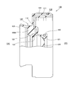
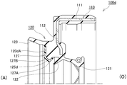
- FIG. 1 is a partially broken cross-sectional view of a sealing device according to Embodiment 1 of the present invention.
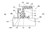
- FIG. 2 is a schematic cross-sectional view showing a state when the shaft of the sealing device according to Embodiment 1 of the present invention is inserted.
- FIG. 3 is a schematic cross-sectional view showing a state in use of the sealing device according to Embodiment 1 of the present invention.
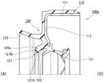
- FIG. 4 is a schematic cross-sectional view of a sealing device according to Embodiment 2 of the present invention.
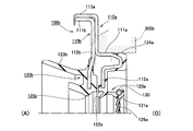
- FIG. 5 is a schematic cross-sectional view of a sealing device according to Embodiment 3 of the present invention.
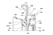
- FIG. 6 is a schematic cross-sectional view of a sealing device according to Embodiment 4 of the present invention.
- FIG. 1 is a partially broken cross-sectional view of a sealing device according to Embodiment 1 of the present invention.
- FIG. 2 is a schematic cross-sectional view showing a state when the shaft of the
- FIG. 7 is a schematic cross-sectional view of a sealing device according to Embodiment 5 of the present invention.
- FIG. 8 is a schematic cross-sectional view of a sealing device according to Embodiment 6 of the present invention.
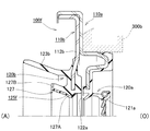
- FIG. 9 is a schematic cross-sectional view of a sealing device according to Embodiment 7 of the present invention.
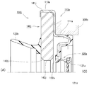
- FIG. 10 is a schematic cross-sectional view of a sealing device according to Embodiment 8 of the present invention.
- FIG. 11 is a schematic cross-sectional view of a sealing device according to Reference Example 1 of the present invention.
- FIG. 12 is a schematic cross-sectional view of a sealing device according to Reference Example 2 of the present invention.
- FIG. 13 is a schematic cross-sectional view of a sealing device according to Reference Example 3 of the present invention.
- FIG. 14 is a schematic cross-sectional view of a conventional sealing device.
- FIGS. 1 is a partially broken cross-sectional view of a sealing device according to Embodiment 1 of the present invention.
- the figure of the cross-section part in FIG. 1 is sectional drawing of the cross section cut
- FIG. 2 is a schematic cross-sectional view showing a state when the shaft of the sealing device according to Embodiment 1 of the present invention is inserted. In FIG. 2, for convenience of explanation, the depth line is appropriately omitted in the cross-sectional view of the sealing device.
- FIG. 3 is a schematic cross-sectional view showing a state in use of the sealing device according to Embodiment 1 of the present invention. 2 and 3 are cross-sectional views of the sealing device taken along a plane including the central axis in the sealing device.
- the sealing device 100 plays a role of sealing an annular gap between the shaft 200 and the housing 300 (see FIG. 3).
- the sealing device 100 includes a metal reinforcing ring 110 and a seal body 120 made of a rubber-like elastic body provided integrally with the reinforcing ring 110.
- the right side in the figure is the sealed region side (O) in which the fluid to be sealed is sealed, and the left side in the figure is the atmosphere side (A) opposite to the sealed region.
- the fluid to be sealed is oil.
- the reinforcing ring 110 includes a cylindrical portion 111 and an inward flange portion 112 that extends radially inward from an end portion on the atmosphere side (A) in the cylindrical portion 111.
- the seal body 120 integrally includes a main lip 121, a dust lip 122, a side lip 123, an outer peripheral seal portion 124, and a bumper portion 125.
- the seal body 120 can be obtained by insert molding using the reinforcing ring 110 as an insert part.
- the main lip 121 extends from the vicinity of the tip of the inward flange portion 112 toward the sealing region side (O), and is configured to slidably contact the outer peripheral surface of the shaft 200.
- a spring 130 is mounted on the outer periphery of the main lip 121 to press the main lip 121 radially inward.
- main lip 121 On the inner peripheral surface of the main lip 121, there is provided a screw portion 126 that exhibits a function of returning the fluid to be sealed to the sealed region side (O) by the rotation of the shaft 200.
- the main lip 121 configured as described above plays a role of suppressing the sealing target fluid from leaking to the atmosphere side (A).
- the dust lip 122 extends from the vicinity of the tip of the inward flange portion 112 toward the atmosphere side (A), and is configured to slidably contact the outer peripheral surface of the shaft 200.
- This dust lip 122 plays a role of suppressing entry of foreign matters such as dust from the outside (atmosphere side (A)) to the sealed region side (O).
- the seal body 120 is provided with a thick portion 120A on the atmosphere side (A) of the inward flange portion 112.
- the side lip 123 is provided so as to extend from the outer peripheral side of the thick portion 120A toward the atmosphere side (A).
- the outer peripheral seal portion 124 is provided so as to cover the outer peripheral surface of the cylindrical portion 111.
- the inner peripheral portion of the thick portion 120 ⁇ / b> A is configured by a bumper portion 125.
- the bumper portion 125 plays a role of mitigating the impact that the dust lip 122 receives from the shaft 200 when the shaft 200 is inserted into the sealing device 100.
- the shaft 200 is a spline shaft that rotates during use.
- the shaft 200 is a stepped shaft including a small diameter portion 210 in which a plurality of grooves are formed and a large diameter portion 220 having a larger outer diameter than the small diameter portion 210.
- the shaft 200 configured in this manner is inserted into the sealing device 100 from the small diameter portion 210 side.
- the shaft 200 is inserted from the atmosphere side (A) to the sealed region side (O), that is, from the dust lip 122 side toward the main lip 121 side (in the direction of arrow A in the figure).
- the inner diameter X of the tip on the inner peripheral side of the bumper portion 125 is larger than the outer diameter Y1 of the portion of the shaft 200 where the main lip 121 and the dust lip 122 slide (that is, the large diameter portion 220). Is set.
- the inner diameter X is set to be smaller than the inner diameter Y2 of the portion having the largest inner diameter in the portion connecting the main lip 121 and the dust lip 122. That is, the inner diameter X, the outer diameter Y1, and the inner diameter Y2 are set so as to satisfy Y1 ⁇ X ⁇ Y2.
- the portion having the largest inner diameter in the portion connecting the main lip 121 and the dust lip 122 corresponds to the root portion of the main lip 121 and also corresponds to the root portion of the dust lip 122.
- the inner diameter X of the tip on the inner peripheral side of the bumper portion 125 may be set larger than the outer diameter Y1 of the large diameter portion 220 by 0.2 mm or more and 2.0 mm or less. it can.
- the sealing device 100 according to the present embodiment plays a role of sealing the annular gap between the shaft 200 and the housing 300 as described above. That is, the outer peripheral seal portion 124 in the sealing device 100 is in close contact with the inner peripheral surface of the shaft hole of the housing 300, so that the gap between the sealing device 100 and the housing 300 is sealed. Further, the main lip 121 and the dust lip 122 in the sealing device 100 are slidably brought into contact with the outer peripheral surface of the large-diameter portion 220 of the shaft 200, so that the gap between the sealing device 100 and the shaft 200 is sealed. .
- a metal slinger 400 is attached to the shaft 200.
- the slinger 400 includes a cylindrical portion 410 fitted to the shaft 200 and an outward flange portion 420 that extends radially outward from an end of the cylindrical portion 410 on the sealing region side (O).
- the side lip 123 of the sealing device 100 is slidably brought into contact with the outward flange portion 420 of the slinger 400. Thereby, it can suppress that a foreign material penetrate
- the inner diameter X of the tip on the inner peripheral side of the bumper portion 125 is larger than the outer diameter Y1 of the portion of the shaft 200 where the main lip 121 and the dust lip 122 slide (that is, the large diameter portion 220). Therefore, it is possible to prevent the insertion force necessary for inserting the shaft 200 from increasing or the bumper portion 125 from being deformed. Further, the inner diameter X of the tip on the inner peripheral side of the bumper portion 125 is smaller than the inner diameter Y2 of the portion having the largest inner diameter in the portion connecting the main lip 121 and the dust lip 122. Therefore, even if the tip end of the shaft 200 hits the bumper portion 125 and the bumper portion 125 is pressed, the dust lip 122 can be effectively prevented from being greatly deformed.
- the tip end of the shaft 200 has a diameter larger than the root portion of the dust lip 122 with respect to the dust lip 122. It is suppressed that it hits the direction outside.
- the bumper portion 125 is constituted by a part of the seal body 120. Thereby, in order to provide the bumper part 125, it is not necessary to increase the number of parts.
- the seal body 120 is provided with a thick portion 120A on the atmosphere side (A) of the inward flange portion 112 in the reinforcing ring 110, and the inner peripheral side of the thick portion 120A is a bumper.
- the unit 125 is configured. Thereby, even if the axis
- FIG. 4 shows a second embodiment of the present invention.
- a configuration in the case where the shape of the bumper portion is different from that of the first embodiment is shown. Since other configurations and operations are the same as those in the first embodiment, the same components are denoted by the same reference numerals and description thereof is omitted.
- FIG. 4 is a schematic cross-sectional view of a sealing device according to Embodiment 2 of the present invention.
- FIG. 4 has shown the cross section cut
- the sealing device 100a according to the present embodiment is also composed of a metal reinforcing ring 110 and a rubber-like elastic seal body 120 provided integrally with the reinforcing ring 110, as in the case of the first embodiment.
- the in the sealing device 100a as in the case of the first embodiment, in use, the right side in the figure is the sealed area side (O) in which the fluid to be sealed is sealed, and the left side in the figure is the sealed area. Is the air side (A) on the opposite side.
- the atmosphere side (A) of the inward flange portion 112 in the seal body 120 is similar to the case of the first embodiment.
- a thick portion 120A is not provided.
- a lip-shaped bumper portion 125a is provided so as to extend from an intermediate portion between the dust lip 122 and the side lip 123 toward the atmosphere side (A) and radially inward.
- the inner diameter of the bumper portion 125a, the inner diameter of the tip on the inner circumference side, the outer diameter of the large diameter portion 220 of the shaft 200 shown in the first embodiment, and the portion having the largest inner diameter in the portion connecting the main lip 121 and the dust lip 122 The dimensional relationship with the inner diameter is the same as in the first embodiment.
- the inner peripheral portion of the thick portion 120A is configured by the bumper portion 125 in the first embodiment, whereas the lip-shaped bumper in the present embodiment. Only the point constituted by the portion 125a is different from the sealing device 100 according to the first embodiment. Also in the sealing device 100a configured as described above, the same effect as in the case of the first embodiment can be obtained. In the case of the present embodiment, since the bumper portion 125a has a lip shape, when the shaft 200 abuts against the bumper portion 125a, the bumper portion 125a is likely to be deformed as compared with the case of the first embodiment. However, the material for the rubber-like elastic body can be reduced as much as there is no thick portion 120A, and the weight can be reduced.
- FIG. 5 shows a third embodiment of the present invention.
- FIG. 5 is a schematic cross-sectional view of a sealing device according to Embodiment 3 of the present invention.
- FIG. 5 has shown the cross section cut
- the sealing device 100b also plays a role of sealing the annular gap between the shaft and the housing 300b.
- the right side in the drawing is the sealed region side (O) where the fluid to be sealed is sealed
- the left side in the drawing is the atmospheric side (A) opposite to the sealed region.
- the shaft is not shown, and the housing 300b is shown by a dotted line.
- the sealing device 100b includes a metal reinforcing ring 110a and a rubber-like elastic seal body 120a provided integrally with the reinforcing ring 110a.
- the reinforcing ring 110a includes a cylindrical portion 111a that is fitted to the inner peripheral surface of the shaft hole of the housing 300b, and an air side (A that is bent into a substantially U shape at the end of the sealed region side (O) of the cylindrical portion 111a. ) And an inward flange portion 112a extending radially inward.
- the seal body 120a integrally includes a main lip 121a, a dust lip 122a, and an outer peripheral seal portion 124a.
- the seal body 120a can be obtained by insert molding using the reinforcing ring 110a as an insert part.
- the main lip 121a extends from the vicinity of the tip of the inward flange portion 112a toward the sealing region side (O), and is configured to slidably contact the outer peripheral surface of the shaft.
- a spring 130 is mounted on the outer periphery of the main lip 121a to press the main lip 121a radially inward.
- a screw portion 126a that exhibits a function of returning the fluid to be sealed to the sealing region side (O) by rotating the shaft.
- the main lip 121a configured as described above plays a role of suppressing the sealing target fluid from leaking to the atmosphere side (A).
- the dust lip 122a extends from the vicinity of the tip of the inward flange portion 112a toward the atmosphere side (A) and is configured to slidably contact the outer peripheral surface of the shaft.
- the dust lip 122a plays a role of suppressing entry of foreign matters such as dust from the outside (atmosphere side (A)) into the sealed region side (O).
- the outer peripheral seal portion 124a is provided so as to cover the outer peripheral portion of the portion bent in a substantially U shape at the end of the cylindrical portion 111a on the sealing region side (O).
- the sealing device 100b which concerns on a present Example is provided with the auxiliary
- the auxiliary reinforcing ring 110b has a cylindrical portion 111b and an inward flange portion 112b extending radially inward from the end of the cylindrical portion 111b on the sealing region side (O).
- assistant reinforcement ring 110b is comprised with respect to the internal peripheral surface of the cylindrical fitting part 113a provided in the radial direction outer side in the reinforcement ring 110a.
- the rubber-like elastic body portion 120b is integrally provided on the auxiliary reinforcing ring 110b.
- the rubber-like elastic body portion 120b can be obtained by insert molding using the auxiliary reinforcing ring 110b as an insert part.
- the rubber-like elastic body portion 120b integrally includes a side lip 123b and a bumper portion 125b.
- the side lip 123b is provided on the atmosphere side (A) of the inward flange portion 112b of the auxiliary reinforcing ring 110b so as to extend toward the atmosphere side (A).
- a bumper portion 125b is provided near the tip of the inward flange portion 112b.
- the bumper portion 125b plays a role of mitigating the impact that the dust lip 122a receives from the shaft when the shaft is inserted into the sealing device 100b.
- the bumper portion 125b according to the present embodiment is configured by a lip-shaped portion extending from the position radially inward of the tip of the inward flange portion 112b toward the atmosphere side (A) and radially outward.
- the sealing device 100b plays a role of sealing the annular gap between the shaft and the housing 300b.
- the cylindrical portion 111a and the outer peripheral seal portion 124a of the reinforcing ring 110a in the sealing device 100b are in close contact with the inner peripheral surface of the shaft hole of the housing 300b, so that the gap between the sealing device 100b and the housing 300b is sealed. Stopped. Further, the main lip 121a and the dust lip 122a in the sealing device 100b slidably contact the outer peripheral surface of the large-diameter portion of the shaft so that the gap between the sealing device 100b and the shaft is sealed.
- a metal slinger is attached to the shaft, and the sealing device 100b against the outward flange portion of the slinger.
- the side lip 123b is configured to come into slidable contact. Thereby, it can suppress that a foreign material penetrate
- the inner diameter of the tip on the inner peripheral side of the bumper portion 125b, the outer diameter of the large diameter portion 220 of the shaft 200 shown in the first embodiment, and the main lip 121a and the dust lip 122a are connected.
- the dimensional relationship with the inner diameter of the portion having the largest inner diameter in the portion is the same as in the case of the first embodiment.
- the sealing device 100b configured as described above, it is possible to obtain the same effect as in the case of the first embodiment.
- an auxiliary reinforcing ring 110b is provided, and a side lip 123b and a bumper portion 125b are provided on the auxiliary reinforcing ring 110b. Therefore, the number of parts increases compared to the case of the first embodiment.
- the bumper portion 125b has a lip shape extending from the position radially inward from the tip of the inward flange portion 112b toward the atmosphere side (A) and radially outward. It is comprised by the site
- FIG. 6 shows a fourth embodiment of the present invention.
- a configuration in the case where the shape of the bumper portion is different from that in the third embodiment is shown. Since other configurations and operations are the same as those of the third embodiment, the same components are denoted by the same reference numerals and description thereof is omitted.
- FIG. 6 is a schematic cross-sectional view of a sealing device according to Example 4 of the present invention.
- FIG. 6 has shown the cross section cut
- the right side in the drawing is the sealed region side (O) in which the fluid to be sealed is sealed
- the left side in the drawing is the left side in the drawing, in the same manner as in the above embodiments. It becomes the atmosphere side (A) opposite to the sealed region.
- the sealing device 100c according to the present embodiment also includes a metal reinforcing ring 110a and a rubber-like elastic seal body 120a provided integrally with the reinforcing ring 110a, as in the third embodiment. I have. Since the configurations of the reinforcing ring 110a and the seal body 120a are the same as those in the third embodiment, the description thereof is omitted.
- the sealing device 100c also includes the auxiliary reinforcing ring 110b and the rubber-like elastic body portion 120c provided integrally with the auxiliary reinforcing ring 110b, as in the case of the third embodiment.
- assistant reinforcement ring 110b since it is the same structure as the case of the said Example 3, the description is abbreviate
- the structure of the rubber-like elastic body part 120c about the structure other than the structure regarding the bumper part 125c, it is the same as the case of the said Example 3.
- a thick portion 120cA is provided on the atmosphere side (A) of the inward flange portion 112b of the auxiliary reinforcing ring 110b. And the inner peripheral part of the thick part 120cA is comprised by the bumper part 125c.
- the inner diameter of the tip on the inner peripheral side of the bumper portion 125c, the outer diameter of the large diameter portion 220 of the shaft 200 shown in the first embodiment, and the main lip 121a and the dust lip 122a are connected.
- the dimensional relationship with the inner diameter of the portion having the largest inner diameter in the portion is the same as that in each of the above embodiments.
- the same effects as those of the third embodiment can be obtained.
- the bumper portion 125c since the inner peripheral portion of the thick portion 120cA is constituted by the bumper portion 125c, the bumper portion 125c can be compared with the case of the third embodiment even when the shaft hits the bumper portion 125c. There is an advantage that it is difficult to deform.
- FIG. 7 shows a fifth embodiment of the present invention.
- the configuration of the sealing device according to the present embodiment is the same as that of the sealing device 100 according to the first embodiment, except that a resin guide is provided in the bumper portion provided in the thick portion of the seal body 120. This is different from the case of the first embodiment. Therefore, only the configuration different from that of the first embodiment will be described below.
- symbol is attached
- FIG. 7 is a schematic cross-sectional view of a sealing device according to Example 5 of the present invention.
- FIG. 7 has shown the cross section cut
- the right side in the drawing is the sealed region side (O) in which the fluid to be sealed is sealed, and the left side in the drawing is the same as in the above embodiments. It becomes the atmosphere side (A) opposite to the sealed region.
- the sealing device 100d according to the present embodiment includes a metal reinforcing ring 110 and a rubber elastic body seal body 120 provided integrally with the reinforcing ring 110, as in the case of the first embodiment. Composed.
- the configuration of the reinforcing ring 110 is the same as that in the first embodiment.
- the configuration of the seal body 120 is basically the same as that in the first embodiment, but the configuration related to the bumper portion is different from that in the first embodiment.
- the thick portion 120dA is provided on the atmosphere side (A) of the inward flange portion 112 of the reinforcing ring 110, and the thick portion 120dA has an inner peripheral portion. It is configured by a bumper portion 125d.
- the annular guide 127 is bonded to the thick portion 120dA and the bumper portion 125d, and the radial direction covers the inner peripheral portion 127A that covers the inner peripheral side of the bumper portion 125d and the atmospheric side (A) of the bumper portion 125d. Part 127B.
- the radial direction portion 127B also covers the atmosphere side (A) of the thick portion 120dA.
- tip of the inner periphery side of the guide 127 which concerns on a present Example is from the site
- the tip of the shaft 200 may abut against the dust lip 122 when the shaft 200 is inserted into the sealing device 100d. It is suppressed.
- an inner peripheral portion 127A of the guide 127 is provided on the inner peripheral side of the bumper portion 125d.
- the guide 127 is made of PTFE having a low frictional resistance. Therefore, since the insertability (slipperiness) of the shaft 200 is improved, it is possible to prevent the insertion force necessary for inserting the shaft 200 from increasing or the bumper portion 125d from being deformed. .
- a radial direction portion 127B of the guide 127 is provided on the atmosphere side (A) of the bumper portion 125d. Therefore, even if the position of the shaft 200 is displaced in the radial direction when the shaft 200 is inserted (even if misalignment occurs), the tip of the shaft 200 abuts against the radial portion 127B, so the bumper portion 125d or the thick portion 120dA. Is prevented from being damaged. Further, since the guide 127 is made of PTFE, even if the shaft 200 hits the guide 127, the shaft 200 is prevented from being damaged.
- the main lip 121 and the dust lip 122 are configured to extend from the vicinity of the tip of the inward flange portion 112 in the reinforcing ring 110. Therefore, even if the tip of the shaft 200 hits the guide 127 and the bumper portion 125d is pushed together with the guide 127, the inward flange portion 112 is hardly deformed, so that the main lip 121 and the dust lip 122 may be greatly deformed. Absent.
- the inner diameter of the tip on the inner peripheral side of the guide 127 is larger than the outer diameter of the large diameter portion 220 of the shaft 200. Therefore, it is possible to prevent the insertion force necessary for the insertion of the shaft 200 from becoming large or the guide 127 and the bumper portion 125d from being deformed. Further, the inner diameter of the tip on the inner peripheral side of the guide 127 is smaller than the inner diameter of the portion having the largest inner diameter in the portion connecting the main lip 121 and the dust lip 122. Therefore, even if the guide 127 is pushed by the end of the shaft 200 abutting against the guide 127, the dust lip 122 can be effectively prevented from being greatly deformed.
- FIG. 8 shows a sixth embodiment of the present invention.
- the configuration of the sealing device according to the present embodiment is the same as that of the sealing device 100a according to the second embodiment, but the second embodiment is that a resin guide is provided in the bumper portion provided in the seal body 120. It is different from the case of. Therefore, only the configuration different from that of the second embodiment will be described below.
- symbol is attached
- FIG. 8 is a schematic cross-sectional view of a sealing device according to Example 6 of the present invention.
- FIG. 8 has shown the cross section cut
- the right side in the drawing is the sealing region side (O) in which the fluid to be sealed is sealed, and the left side in the drawing is opposite to the sealing region. It becomes the atmosphere side (A) of the side.
- the sealing device 100e according to the present embodiment is similar to the sealing device 100a according to the second embodiment, and is made of a metal reinforcing ring 110 and a rubber-like elastic seal body provided integrally with the reinforcing ring 110. 120.
- the configuration of the reinforcing ring 110 is the same as that in the second embodiment.
- the configuration of the seal body 120 is basically the same as that in the second embodiment, but the configuration related to the bumper portion is different from that in the second embodiment. Accordingly, only the configuration related to the bumper portion 125e will be described below.
- the intermediate portion between the dust lip 122 and the side lip 123 faces the atmosphere side (A) and radially inward.
- a lip-shaped bumper portion 125e is provided so as to extend.
- the guide 127 made from PTFE is provided in the inner peripheral side of the bumper part 125e, and the atmosphere side (A).
- the guide 127 is bonded to the bumper portion 125e, and includes an inner peripheral portion 127A that covers the inner peripheral side of the bumper portion 125e, and a radial direction portion 127B that covers the atmosphere side (A) of the bumper portion 125e. .
- the dimensional relationship between the inner diameter of the distal end on the inner peripheral side of the guide 127, the outer diameter of the large-diameter portion 220 of the shaft 200, and the inner diameter of the portion having the largest inner diameter in the portion connecting the main lip 121 and the dust lip 122. is the same as in the case of the fifth embodiment.
- the same effect as in the case of the fifth embodiment can be obtained.
- the material for the rubber-like elastic body can be reduced as in the second embodiment, so that the weight can be reduced.
- FIG. 9 shows a seventh embodiment of the present invention.
- the configuration of the sealing device according to the present embodiment is the same as that of the sealing device 100b according to the third embodiment, except that a resin guide is provided in the bumper portion provided in the rubber-like elastic body portion 120b. This is different from the case of the third embodiment. Therefore, only the configuration different from that in the third embodiment will be described below.
- symbol is attached
- FIG. 9 is a schematic cross-sectional view of a sealing device according to Example 7 of the present invention.
- FIG. 9 has shown the cross section cut
- the sealing device 100f according to the present embodiment also plays a role of sealing the annular gap between the shaft and the housing 300b.
- the right side in the figure is the sealed region side (O) in which the fluid to be sealed is sealed
- the left side in the figure is the atmosphere side (A) opposite to the sealed region.
- the shaft is not shown, and the housing 300b is shown by a dotted line.
- the sealing device 100f according to the present embodiment is similar to the sealing device 100b according to the third embodiment, and is made of a metal reinforcing ring 110a and a rubber-like elastic seal body provided integrally with the reinforcing ring 110a. 120a and an auxiliary reinforcing ring 110b fixed to the reinforcing ring 110a by fitting.
- the configurations of the reinforcing ring 110a and the seal body 120a are the same as those in the third embodiment.
- the configuration of the auxiliary reinforcing ring 110b is basically the same as that of the third embodiment, but the configuration related to the bumper portion of the rubber-like elastic body portion 120b is different from that of the third embodiment. Therefore, only the configuration different from that in the third embodiment will be described below.
- the rubber-like elastic body portion 120b integrally includes a side lip 123b and a bumper portion 125f.
- the bumper portion 125f is provided in the vicinity of the tip of the inward flange portion 112b, similarly to the bumper portion 125b of the sealing device 100b according to the third embodiment, and the dust lip 122a is inserted when the shaft is inserted into the sealing device 100f. It plays a role to alleviate the impact received from the shaft.
- the bumper portion 125f is formed by a lip-shaped portion extending from the position radially inward from the tip of the inward flange portion 112b toward the atmosphere side (A) and radially outward. It is configured.
- the guide 127 made from PTFE is provided in the inner peripheral side of the bumper part 125f, and the air
- the guide 127 is bonded to the bumper portion 125f, and an inner peripheral portion 127A that covers the inner peripheral side of the bumper portion 125f, and the air side (A) of the bumper portion 125f (the air side (A) in the lip-shaped part) ) In the radial direction 127B.
- the same effect as in the case of the fifth embodiment can be obtained.
- the inner peripheral side of the lip-shaped portion extending toward the atmosphere side (A) and radially outward in the bumper portion 125f is covered with the inner peripheral portion 127A of the guide 127, and
- the air side (A) of the lip-shaped part is covered with the radial part 127B of the guide 127.
- FIG. 10 shows an eighth embodiment of the present invention.
- the configuration of the sealing device according to the present embodiment is the same as that of the sealing device 100c according to the fourth embodiment, except that a resin guide is provided in the bumper portion provided in the rubber-like elastic body portion 120c. This is different from the case of the fourth embodiment. Therefore, only the configuration different from that of the fourth embodiment will be described below.
- symbol is attached
- FIG. 10 is a schematic cross-sectional view of a sealing device according to Example 8 of the present invention.
- FIG. 10 has shown the cross section cut
- the sealing device 100g according to the present embodiment also plays a role of sealing the annular gap between the shaft and the housing 300b.
- the right side in the figure is the sealed area side (O) where the fluid to be sealed is sealed
- the left side in the figure is the atmosphere side (A) opposite to the sealed area.
- the shaft is not shown, and the housing 300b is shown by a dotted line.
- the sealing device 100g according to the present embodiment is provided on the metal reinforcing ring 110a, the seal body 120a, the auxiliary reinforcing ring 110b, and the auxiliary reinforcing ring 110b, similarly to the sealing device 100c according to the fourth embodiment.
- the rubber-like elastic body portion 120g is provided.
- the configurations of the reinforcing ring 110a, the seal body 120a, and the auxiliary reinforcing ring 110b are the same as those in the fourth embodiment.
- the configuration of the rubber-like elastic body portion 120g is basically the same as that of the rubber-like elastic body portion 120c of the fourth embodiment, but the configuration relating to the bumper portion is different from that of the fourth embodiment. Therefore, only the configuration different from that of the fourth embodiment will be described below.
- a thick portion 120gA is provided on the atmosphere side (A) of the inward flange portion 112b.
- the inner peripheral part of the thick part 120gA is comprised by the bumper part 125g,
- the guide 127 made from PTFE is provided in the inner peripheral side of the bumper part 125g, and the air
- the guide 127 is bonded to the rubber-like elastic body portion 120g, and an inner peripheral portion 127A that covers the inner peripheral side of the bumper portion 125g and a radial direction portion 127B that covers the atmosphere side (A) of the bumper portion 125g. It consists of.
- the radial portion 127B also covers the atmosphere side (A) of the thick portion 120gA of the rubber-like elastic body portion 120g.
- the dimensional relationship between the inner diameter of the distal end on the inner peripheral side of the guide 127, the outer diameter of the large-diameter portion 220 of the shaft 200, and the inner diameter of the largest inner diameter portion in the portion connecting the main lip 121a and the dust lip 122a. is the same as in the case of Examples 5 to 7.
- the same effect as in the case of Example 5 can be obtained.
- the atmospheric side (A) of the thick portion 120gA of the rubber-like elastic body portion 120g is also covered with the radial portion 127B of the guide 127. Accordingly, when the shaft is inserted into the sealing device 100g, even if the position of the shaft is greatly displaced in the radial direction (even if a large misalignment occurs), the tip of the shaft abuts against the radial portion 127B. It is suppressed that the bumper part 125g and the thick part 120gA are damaged.
- a metal slinger is attached to the shaft, and each sealing device is attached to the outward flange portion of the slinger.
- the side lip 123b may be slidably contacted. Thereby, it can suppress that a foreign material penetrate
- a bumper portion for reducing the impact received by the dust lip from the inserted shaft is provided.
- a guide is provided for guiding the inserted shaft in a direction in which the central axis line coincides with the central axis line of the sealing device. This prevents the tip of the shaft from striking against the dust lip or main lip even when the shaft is displaced in the radial direction when the shaft is inserted. Is suppressed.
- FIG. 12 and FIG. 13 are schematic cross-sectional views of sealing devices according to Reference Example 1, Reference Example 2 and Reference Example 3 of the present invention, respectively.
- 11 to 13 show a cross section of the sealing device taken along a plane including the central axis of the sealing device.
- the right side in the drawing is a sealed region in which the fluid to be sealed is sealed in use.
- the left side in the figure is the atmosphere side (A) opposite to the sealed region.
- each reference example also includes a metal reinforcing ring 110a and a rubber-like elastic seal body 120a provided integrally with the reinforcing ring 110a, as in the case of the third embodiment. ing.
- each reference example unlike the third embodiment, includes a guide for guiding the inserted shaft instead of the bumper portion.
- each reference example will be described in order.
- symbol is attached
- the sealing device 100h according to Reference Example 1 includes an auxiliary reinforcing ring 110h that is fixed to the reinforcing ring 110a by fitting.
- the auxiliary reinforcing ring 110h extends inward in the radial direction from the cylindrical portion 111h fitted to the inner peripheral surface of the fitting portion 113a of the reinforcing ring 110a and the end of the cylindrical portion 111h on the sealing region side (O).
- a flange portion 112h is integrally provided with a side lip 123b extending from the front end of the flange portion 112h toward the atmosphere side (A).
- the sealing device 100h includes a guide 140h that is fixed to the reinforcing ring 110a by fitting.
- the annular guide 140h includes a cylindrical portion 141h that is fitted to the inner peripheral surface of the cylindrical portion 111a of the reinforcing ring 110a, and a flange portion that extends radially inward from the atmosphere side (A) end of the cylindrical portion 141h. 142h.
- the guide 140h extends from the tip on the inner peripheral side of the flange portion 142h toward the atmosphere side (A), and from the atmosphere side (A) end of the cylinder portion 143h toward the atmosphere side (A).
- an enlarged-diameter portion 144h that expands while expanding.
- the inner diameter of the cylindrical portion 143h is set larger than the outer diameter Y1 (see FIG. 2) of the large-diameter portion 220 of the shaft 200.
- the taper surface 145h which diameter-expands toward the atmosphere side (A) is formed in the edge part of the atmosphere side (A) of the diameter expansion part 144h.
- the tip end of the shaft 200 is the enlarged-diameter portion 144h. It hits the inner peripheral surface.
- the inserted shaft 200 is guided in a direction in which the central axis thereof coincides with the central axis of the sealing device 100h.
- the tip of the shaft 200 is prevented from striking against the dust lip 122a and the main lip 121a, so that the inversion of the dust lip 122a and the damage to the dust lip 122a and the main lip 121a are suppressed.
- the tapered surface 145h that expands toward the atmosphere side (A) is formed at the end of the diameter expansion portion 144h on the atmosphere side (A). However, it is smoothly guided in the direction in which the central axis coincides with the central axis of the sealing device 100h.
- FIG. 12 shows a sealing device 100i according to Reference Example 2 of the present invention.
- the shape of the guide is different from that of the reference example 1.
- the sealing device 100i includes a guide 140i that is fixed to the reinforcing ring 110a by an auxiliary reinforcing ring 110h.
- the annular guide 140i includes a radial portion 141i having an outer diameter that is substantially equal to the inner diameter of the fitting portion 113a of the reinforcing ring 110a.
- the guide 140i is curved from the tip on the inner peripheral side of the radial portion 141i toward the atmosphere side (A) and from the end on the atmosphere side (A) of the bending portion 142i toward the radially inner side. And a radial portion 143i extending.
- the inner diameter of the radial portion 143i is set larger than the outer diameter Y1 (see FIG. 2) of the large diameter portion 220 of the shaft 200. Accordingly, when the shaft 200 is inserted into the sealing device 100i, even if the position of the shaft 200 is displaced in the radial direction, the tip of the shaft 200 contacts the radial portion 143i.
- the inserted shaft 200 is guided in a direction in which the central axis thereof coincides with the central axis of the sealing device 100i.
- the same effect as in the case of the reference example 1 can be obtained.
- atmosphere side (A) may be formed in the edge part of the inner peripheral side of the radial direction part 143i.
- FIG. 13 shows a sealing device 100j according to Reference Example 3 of the present invention.
- the shape of the guide is different from the above-described reference examples, and no auxiliary reinforcing ring is provided.
- the sealing device 100j includes a guide 140j that is fixed to the reinforcing ring 110a by fitting.
- the annular guide 140j includes an outer peripheral surface 141j that is fitted to the inner peripheral surface of the fitting portion 113a of the reinforcing ring 110a.
- the guide 140j includes an inner peripheral surface 142j having an inner diameter larger than the outer diameter Y1 (see FIG.
- a tapered surface 143j whose diameter increases toward the side (A) is formed. Accordingly, when the shaft 200 is inserted into the sealing device 100j, even if the position of the shaft 200 is displaced in the radial direction, the tip of the shaft 200 contacts the tapered surface 143j of the guide 140j. As a result, the inserted shaft 200 is guided in a direction in which the central axis thereof coincides with the central axis of the sealing device 100j. As a result, also in the sealing device 100j, it is possible to obtain the same effect as in the case of each of the above reference examples.
- a side lip 123b extending toward the atmosphere side (A) is integrally provided on the end surface of the guide 140j on the atmosphere side (A).
- a metal slinger is attached to the shaft in the same manner as in the first embodiment, and the side of each sealing device is opposed to the outward flange portion of the slinger.
- the lip 123b may be configured to come into slidable contact. Thereby, it can suppress that a foreign material penetrate
Landscapes
- Engineering & Computer Science (AREA)
- General Engineering & Computer Science (AREA)
- Mechanical Engineering (AREA)
- Physics & Mathematics (AREA)
- Fluid Mechanics (AREA)
- Sealing With Elastic Sealing Lips (AREA)
- Sealing Devices (AREA)
Abstract
Description
軸とハウジングとの間の環状隙間を密封する密封装置であって、
内向きフランジ部を有する補強環と、
該補強環に一体的に設けられるゴム状弾性体製のシール本体であって、前記内向きフランジ部の先端付近から密封領域側に向かって伸び、前記軸の外周表面に摺動自在に接触するメインリップと、前記内向きフランジ部の先端付近から密封領域とは反対側に向かって伸び、前記軸の外周表面に摺動自在に接触するダストリップと、を有するシール本体と、
を備える密封装置において、
前記ダストリップよりも密封領域とは反対側に、前記軸が密封装置内に挿入される際に前記ダストリップが前記軸から受ける衝撃を緩和するゴム状弾性体製のバンパー部が設けられており、該バンパー部の内周側の先端の内径は、前記軸における前記メインリップ及びダストリップが摺動する部位の外径よりも大きく、かつ前記メインリップとダストリップとを繋ぐ部分における最も内径の大きな部位の内径よりも小さく設定されていることを特徴とする。
軸とハウジングとの間の環状隙間を密封する密封装置であって、
内向きフランジ部を有する補強環と、
該補強環に一体的に設けられるゴム状弾性体製のシール本体であって、前記内向きフランジ部の先端付近から密封領域側に向かって伸び、前記軸の外周表面に摺動自在に接触するメインリップと、前記内向きフランジ部の先端付近から密封領域とは反対側に向かって伸び、前記軸の外周表面に摺動自在に接触するダストリップと、を有するシール本体と、
を備える密封装置において、
前記ダストリップよりも密封領域とは反対側に、前記軸が密封装置内に挿入される際に前記ダストリップが前記軸から受ける衝撃を緩和するゴム状弾性体製のバンパー部が設けられると共に、前記バンパー部における内周側と、密封領域とは反対側とに、前記軸を密封装置内に導く樹脂製のガイドが設けられており、該ガイドの内周側の先端の内径は、前記軸における前記メインリップ及びダストリップが摺動する部位の外径よりも大きく、かつ前記メインリップとダストリップとを繋ぐ部分における最も内径の大きな部位の内径よりも小さく設定されていることを特徴とする。
図1~図3を参照して、本発明の実施例1に係る密封装置について説明する。図1は本発明の実施例1に係る密封装置の一部破断断面図である。なお、図1における断面部分の図は、密封装置における中心軸線を含む面で切断した断面の断面図である。図2は本発明の実施例1に係る密封装置の軸挿入時の様子を示す模式的断面図である。なお、図2においては、説明の便宜上、密封装置の断面図において、奥行き線を適宜省略している。図3は本発明の実施例1に係る密封装置の使用時の状態を示す模式的断面図である。図2及び図3における密封装置の断面図は、密封装置における中心軸線を含む面で切断した断面を示す図である。
特に、図1を参照して、本実施例に係る密封装置100の構成について説明する。なお、本実施例に係る密封装置100は、軸200とハウジング300との間の環状隙間を密封する役割を担っている(図3参照)。密封装置100は、金属製の補強環110と、補強環110に一体的に設けられるゴム状弾性体製のシール本体120とから構成される。この密封装置100は、使用時においては、図中右側が、密封対象流体が密封されている密封領域側(O)となり、図中左側が密封領域とは反対側の大気側(A)となる。なお、本実施例においては、密封対象流体はオイルである。
特に、図2を参照して、バンパー部125について、より詳しく説明する。本実施例に係る軸200は、使用時に回転するスプライン軸である。この軸200は、複数の溝が形成されている小径部210と、小径部210よりも外径が大きな大径部220とを備える段付きの軸である。なお、使用時においては、メインリップ121及びダストリップ122は、大径部220に対して摺動する。このように構成される軸200は、小径部210側から密封装置100内に挿入される。また、軸200は、大気側(A)から密封領域側(O)、つまりダストリップ122側からメインリップ121側(図中、矢印A方向)に向かって挿入される。
特に、図3を参照して、本実施例に係る密封装置100の使用状態について説明する。本実施例に係る密封装置100は、上記の通り、軸200とハウジング300との間の環状隙間を密封する役割を担っている。すなわち、密封装置100における外周シール部124がハウジング300の軸孔内周面に密着することで、密封装置100とハウジング300との間の隙間が封止される。また、密封装置100におけるメインリップ121とダストリップ122が軸200の大径部220の外周表面に摺動自在に接触することで、密封装置100と軸200との間の隙間が封止される。
以上のように構成された本実施例に係る密封装置100によれば、バンパー部125が設けられているので、軸200を密封装置100内に挿入する際に軸200の先端がダストリップ122に突き当たってしまうことが抑制される。また、バンパー部125はゴム状弾性体製であるので、軸200がバンパー部125に突き当たっても、軸200が損傷してしまうことは抑制される。また、メインリップ121及びダストリップ122は、補強環110における内向きフランジ部112の先端付近から伸びる構成である。従って、軸200の先端がバンパー部125に突き当たり、バンパー部125が押されても、内向きフランジ部112は殆ど変形しないので、メインリップ121及びダストリップ122が大きく変形してしまうこともない。
図4には、本発明の実施例2が示されている。本実施例においては、バンパー部の形状が、上記実施例1とは異なる場合の構成を示す。その他の構成および作用については実施例1と同一なので、同一の構成部分については同一の符号を付して、その説明は省略する。
図5には、本発明の実施例3が示されている。図5は本発明の実施例3に係る密封装置の模式的断面図である。なお、図5は、密封装置について、密封装置における中心軸線を含む面で切断した断面を示している。
図6には、本発明の実施例4が示されている。本実施例においては、バンパー部の形状が、上記実施例3とは異なる場合の構成を示す。その他の構成および作用については実施例3と同一なので、同一の構成部分については同一の符号を付して、その説明は省略する。
図7には、本発明の実施例5が示されている。本実施例に係る密封装置の構成は、上記実施例1に係る密封装置100と同様であるが、シール本体120の肉厚部分に設けられたバンパー部に樹脂製のガイドが設けられている点で実施例1の場合と異なる。従って、以下、実施例1の場合と異なる構成についてのみ説明する。なお、実施例1に係る密封装置100と同一の構成部分については同一の符号を付して、その説明は省略する。
図8には、本発明の実施例6が示されている。本実施例に係る密封装置の構成は、上記実施例2に係る密封装置100aと同様であるが、シール本体120に設けられたバンパー部に樹脂製のガイドが設けられている点で実施例2の場合と異なる。従って、以下、実施例2の場合と異なる構成についてのみ説明する。なお、実施例2に係る密封装置100aと同一の構成部分については同一の符号を付して、その説明は省略する。
図9には、本発明の実施例7が示されている。本実施例に係る密封装置の構成は、上記実施例3に係る密封装置100bと同様であるが、ゴム状弾性体部120bに設けられたバンパー部に樹脂製のガイドが設けられている点で実施例3の場合と異なる。従って、以下、実施例3の場合と異なる構成についてのみ説明する。なお、実施例3に係る密封装置100bと同一の構成部分については同一の符号を付して、その説明は省略する。
図10には、本発明の実施例8が示されている。本実施例に係る密封装置の構成は、上記実施例4に係る密封装置100cと同様であるが、ゴム状弾性体部120cに設けられたバンパー部に樹脂製のガイドが設けられている点で実施例4の場合と異なる。従って、以下、実施例4の場合と異なる構成についてのみ説明する。なお、実施例4に係る密封装置100cと同一の構成部分については同一の符号を付して、その説明は省略する。
上記の各実施例においては、挿入される軸からダストリップが受ける衝撃を緩和させるためのバンパー部が設けられていた。これに対し、以下に説明する参考例においては、バンパー部に替えて、挿入される軸を、その中心軸線と密封装置の中心軸線とが一致する方向に導くためのガイドが設けられている。これにより、軸の挿入時に軸の位置が径方向にずれたとしても、軸の先端がダストリップやメインリップに突き当たることが抑制されるため、ダストリップの反転や、ダストリップやメインリップの損傷が抑制される。
110,110a 補強環
110b 補助補強環
111,111a,111b 円筒部
112,112a,112b 内向きフランジ部
113a 嵌合部
120,120a シール本体
120A 肉厚部分
120b,120c,120d ゴム状弾性体部
120cA,120dA 肉厚部分
121,121a メインリップ
122,122a ダストリップ
123,123b サイドリップ
124,124a 外周シール部
125,125a,125b,125c,125d バンパー部
126,126a ネジ部
127 ガイド
130 スプリング
140h,140i,140j ガイド
200 軸
210 小径部
220 大径部
300,300b ハウジング
400 スリンガー
410 円筒部
420 フランジ部
Claims (4)
- 軸とハウジングとの間の環状隙間を密封する密封装置であって、
内向きフランジ部を有する補強環と、
該補強環に一体的に設けられるゴム状弾性体製のシール本体であって、前記内向きフランジ部の先端付近から密封領域側に向かって伸び、前記軸の外周表面に摺動自在に接触するメインリップと、前記内向きフランジ部の先端付近から密封領域とは反対側に向かって伸び、前記軸の外周表面に摺動自在に接触するダストリップと、を有するシール本体と、
を備える密封装置において、
前記ダストリップよりも密封領域とは反対側に、前記軸が密封装置内に挿入される際に前記ダストリップが前記軸から受ける衝撃を緩和するゴム状弾性体製のバンパー部が設けられており、該バンパー部の内周側の先端の内径は、前記軸における前記メインリップ及びダストリップが摺動する部位の外径よりも大きく、かつ前記メインリップとダストリップとを繋ぐ部分における最も内径の大きな部位の内径よりも小さく設定されていることを特徴とする密封装置。 - 軸とハウジングとの間の環状隙間を密封する密封装置であって、
内向きフランジ部を有する補強環と、
該補強環に一体的に設けられるゴム状弾性体製のシール本体であって、前記内向きフランジ部の先端付近から密封領域側に向かって伸び、前記軸の外周表面に摺動自在に接触するメインリップと、前記内向きフランジ部の先端付近から密封領域とは反対側に向かって伸び、前記軸の外周表面に摺動自在に接触するダストリップと、を有するシール本体と、
を備える密封装置において、
前記ダストリップよりも密封領域とは反対側に、前記軸が密封装置内に挿入される際に前記ダストリップが前記軸から受ける衝撃を緩和するゴム状弾性体製のバンパー部が設けられると共に、前記バンパー部における内周側と、密封領域とは反対側とに、前記軸を密封装置内に導く樹脂製のガイドが設けられており、該ガイドの内周側の先端の内径は、前記軸における前記メインリップ及びダストリップが摺動する部位の外径よりも大きく、かつ前記メインリップとダストリップとを繋ぐ部分における最も内径の大きな部位の内径よりも小さく設定されていることを特徴とする密封装置。 - 前記バンパー部は、前記シール本体の一部により構成されることを特徴とする請求項1または2に記載の密封装置。
- 前記シール本体には、前記内向きフランジ部の密封領域とは反対側に肉厚部分が設けられており、該肉厚部分の内周側がバンパー部により構成されていることを特徴とする請求項3に記載の密封装置。
Priority Applications (5)
| Application Number | Priority Date | Filing Date | Title |
|---|---|---|---|
| KR1020167031799A KR101861470B1 (ko) | 2014-05-20 | 2015-05-15 | 밀봉장치 |
| EP15796984.1A EP3147544B1 (en) | 2014-05-20 | 2015-05-15 | Sealing device |
| CN201580025477.8A CN106461085B (zh) | 2014-05-20 | 2015-05-15 | 密封装置 |
| US15/311,926 US10208861B2 (en) | 2014-05-20 | 2015-05-15 | Sealing device |
| JP2016521066A JP5971450B2 (ja) | 2014-05-20 | 2015-05-15 | 密封装置 |
Applications Claiming Priority (4)
| Application Number | Priority Date | Filing Date | Title |
|---|---|---|---|
| JP2014104302 | 2014-05-20 | ||
| JP2014-104302 | 2014-05-20 | ||
| JP2014171784 | 2014-08-26 | ||
| JP2014-171784 | 2014-08-26 |
Publications (1)
| Publication Number | Publication Date |
|---|---|
| WO2015178292A1 true WO2015178292A1 (ja) | 2015-11-26 |
Family
ID=54553964
Family Applications (1)
| Application Number | Title | Priority Date | Filing Date |
|---|---|---|---|
| PCT/JP2015/063971 Ceased WO2015178292A1 (ja) | 2014-05-20 | 2015-05-15 | 密封装置 |
Country Status (6)
| Country | Link |
|---|---|
| US (1) | US10208861B2 (ja) |
| EP (1) | EP3147544B1 (ja) |
| JP (1) | JP5971450B2 (ja) |
| KR (1) | KR101861470B1 (ja) |
| CN (1) | CN106461085B (ja) |
| WO (1) | WO2015178292A1 (ja) |
Cited By (1)
| Publication number | Priority date | Publication date | Assignee | Title |
|---|---|---|---|---|
| CN117030256A (zh) * | 2023-08-18 | 2023-11-10 | 南通市嘉诚机械有限公司 | 一种汽车轴承部件用密封式测试装置 |
Families Citing this family (12)
| Publication number | Priority date | Publication date | Assignee | Title |
|---|---|---|---|---|
| CN106461086B (zh) * | 2014-06-10 | 2019-01-15 | Nok株式会社 | 密封装置 |
| CN107923536B (zh) * | 2015-09-03 | 2018-11-20 | Nok株式会社 | 密封结构 |
| USD802104S1 (en) * | 2015-09-25 | 2017-11-07 | Nok Corporation | Seal |
| JP6921491B2 (ja) * | 2016-09-20 | 2021-08-18 | Nok株式会社 | 密封装置 |
| JP2020513096A (ja) * | 2017-04-07 | 2020-04-30 | デーナ、オータモウティヴ、システィムズ、グループ、エルエルシー | 一体的に形成されたリブを有するシーリング部材 |
| US20190226584A1 (en) * | 2018-01-19 | 2019-07-25 | American Axle & Manufacturing, Inc. | Lip seal with air-side spring |
| US11781653B2 (en) | 2018-07-09 | 2023-10-10 | Nok Corporation | Sealing device |
| US12044314B2 (en) * | 2019-09-30 | 2024-07-23 | Nok Corporation | Sealing device |
| US11454259B2 (en) * | 2020-01-23 | 2022-09-27 | DRiV Automotive Inc. | Hydraulic assembly |
| CN112483740A (zh) * | 2020-11-26 | 2021-03-12 | 江西爱森德实业有限公司 | 一种节流承插式无垫连接管材 |
| US12578018B2 (en) | 2021-10-26 | 2026-03-17 | Nok Corporation | Steering dust seal and sealing device |
| US20240421659A1 (en) * | 2023-06-14 | 2024-12-19 | Borgwarner Inc. | Rotating machine and drive module assembly including the same |
Citations (2)
| Publication number | Priority date | Publication date | Assignee | Title |
|---|---|---|---|---|
| JPS5751870U (ja) * | 1980-09-09 | 1982-03-25 | ||
| JP2005233218A (ja) * | 2004-02-17 | 2005-09-02 | Nok Corp | 密封装置 |
Family Cites Families (22)
| Publication number | Priority date | Publication date | Assignee | Title |
|---|---|---|---|---|
| JPS60184461U (ja) * | 1984-05-17 | 1985-12-06 | エヌオーケー株式会社 | オイルシ−ル |
| JPH0511405Y2 (ja) * | 1986-02-21 | 1993-03-22 | ||
| JPH04128576A (ja) | 1990-09-17 | 1992-04-30 | Matsushita Refrig Co Ltd | 密閉型電動圧縮機の電装部品保護装置 |
| JPH04128576U (ja) | 1991-05-20 | 1992-11-24 | エヌオーケー株式会社 | オイルシール |
| CA2114818A1 (en) | 1993-07-19 | 1995-01-20 | David E. Beth | Oscillating spindle sander |
| JP2599517Y2 (ja) | 1993-11-17 | 1999-09-13 | エヌオーケー株式会社 | 密封装置 |
| JP3359462B2 (ja) | 1995-03-14 | 2002-12-24 | エヌオーケー株式会社 | 密封装置 |
| JP3581969B2 (ja) * | 1995-06-16 | 2004-10-27 | Nok株式会社 | 密封装置 |
| US5577741A (en) * | 1995-07-17 | 1996-11-26 | Brenco Incorporated | Combination lip and sleeve seal and its method of manufacture |
| JP3893761B2 (ja) * | 1998-07-22 | 2007-03-14 | Nok株式会社 | 密封装置 |
| US6325187B1 (en) * | 1999-05-12 | 2001-12-04 | Tenneco Automotive Inc. | Dirt wiper system for suspension damper |
| JP4399930B2 (ja) * | 1999-12-06 | 2010-01-20 | Nok株式会社 | 密封装置 |
| JP2002188730A (ja) * | 2000-12-25 | 2002-07-05 | Showa Corp | 往復動用オイルシールのダストリップ構造 |
| JP2003014135A (ja) | 2001-06-29 | 2003-01-15 | Nok Corp | 密封装置 |
| JP2004301161A (ja) * | 2003-03-28 | 2004-10-28 | Kayaba Ind Co Ltd | ストラット型ショックアブソーバ |
| JP2008111509A (ja) | 2006-10-31 | 2008-05-15 | Nok Corp | オイルシール |
| JP5209940B2 (ja) * | 2007-11-13 | 2013-06-12 | カヤバ工業株式会社 | 高摩擦流体シール及び緩衝器 |
| JP5263869B2 (ja) * | 2008-02-05 | 2013-08-14 | Ntn株式会社 | 軸受シールおよびその軸受シール成形用金型 |
| CN201884661U (zh) * | 2010-12-19 | 2011-06-29 | 揭阳市天诚密封件有限公司 | 后端盖组合式油封 |
| JP5702676B2 (ja) * | 2011-06-22 | 2015-04-15 | カヤバ工業株式会社 | オイルシール |
| DE102012016559A1 (de) * | 2012-08-22 | 2014-02-27 | Carl Freudenberg Kg | Dichtungsanordnung und Protektorring |
| EP3211278B1 (en) * | 2014-10-22 | 2019-09-18 | Nok Corporation | Dust cover |
-
2015
- 2015-05-15 CN CN201580025477.8A patent/CN106461085B/zh active Active
- 2015-05-15 JP JP2016521066A patent/JP5971450B2/ja active Active
- 2015-05-15 KR KR1020167031799A patent/KR101861470B1/ko active Active
- 2015-05-15 EP EP15796984.1A patent/EP3147544B1/en active Active
- 2015-05-15 US US15/311,926 patent/US10208861B2/en active Active
- 2015-05-15 WO PCT/JP2015/063971 patent/WO2015178292A1/ja not_active Ceased
Patent Citations (2)
| Publication number | Priority date | Publication date | Assignee | Title |
|---|---|---|---|---|
| JPS5751870U (ja) * | 1980-09-09 | 1982-03-25 | ||
| JP2005233218A (ja) * | 2004-02-17 | 2005-09-02 | Nok Corp | 密封装置 |
Non-Patent Citations (1)
| Title |
|---|
| See also references of EP3147544A4 * |
Cited By (2)
| Publication number | Priority date | Publication date | Assignee | Title |
|---|---|---|---|---|
| CN117030256A (zh) * | 2023-08-18 | 2023-11-10 | 南通市嘉诚机械有限公司 | 一种汽车轴承部件用密封式测试装置 |
| CN117030256B (zh) * | 2023-08-18 | 2024-04-19 | 南通市嘉诚机械有限公司 | 一种汽车轴承部件用密封式测试装置 |
Also Published As
| Publication number | Publication date |
|---|---|
| KR20160145136A (ko) | 2016-12-19 |
| US10208861B2 (en) | 2019-02-19 |
| JP5971450B2 (ja) | 2016-08-17 |
| EP3147544A4 (en) | 2018-02-28 |
| EP3147544A1 (en) | 2017-03-29 |
| KR101861470B1 (ko) | 2018-05-28 |
| EP3147544B1 (en) | 2024-10-23 |
| CN106461085A (zh) | 2017-02-22 |
| US20170122438A1 (en) | 2017-05-04 |
| JPWO2015178292A1 (ja) | 2017-04-20 |
| EP3147544C0 (en) | 2024-10-23 |
| CN106461085B (zh) | 2018-06-22 |
Similar Documents
| Publication | Publication Date | Title |
|---|---|---|
| JP5971450B2 (ja) | 密封装置 | |
| US8066287B2 (en) | Dynamic seal | |
| US8590903B2 (en) | Lip seal with inversion prevention feature | |
| US8720901B2 (en) | Seal ring | |
| CN107076306B (zh) | 密封装置 | |
| JP2015014303A (ja) | 密封装置 | |
| WO2005028929A1 (ja) | 密封装置 | |
| JPWO2006049152A1 (ja) | 軸受けシール | |
| US7854432B2 (en) | Dynamic seal | |
| CN113544416B (zh) | 密封装置 | |
| JP6921491B2 (ja) | 密封装置 | |
| WO2016027695A1 (ja) | 密封構造 | |
| JP6775295B2 (ja) | デフサイド用の密封装置 | |
| US11835136B2 (en) | Sealing device | |
| JP2021167641A (ja) | 密封装置 | |
| US20060116212A1 (en) | Boot for constant velocity universal joint | |
| JP2021156314A (ja) | 密封装置 | |
| JP2015048904A (ja) | 密封装置 | |
| CN113614425A (zh) | 密封装置 | |
| JP2017089803A (ja) | 密封装置 | |
| JP7164335B2 (ja) | 密封装置 | |
| BRPI0618880A2 (pt) | vedação dinámica | |
| JP2017180576A (ja) | 密封部材 | |
| CN103711901B (zh) | 多部件活塞 | |
| JP2008286320A (ja) | 密封装置 |
Legal Events
| Date | Code | Title | Description |
|---|---|---|---|
| ENP | Entry into the national phase |
Ref document number: 2016521066 Country of ref document: JP Kind code of ref document: A |
|
| 121 | Ep: the epo has been informed by wipo that ep was designated in this application |
Ref document number: 15796984 Country of ref document: EP Kind code of ref document: A1 |
|
| ENP | Entry into the national phase |
Ref document number: 20167031799 Country of ref document: KR Kind code of ref document: A |
|
| WWE | Wipo information: entry into national phase |
Ref document number: 15311926 Country of ref document: US |
|
| NENP | Non-entry into the national phase |
Ref country code: DE |
|
| REEP | Request for entry into the european phase |
Ref document number: 2015796984 Country of ref document: EP |
|
| WWE | Wipo information: entry into national phase |
Ref document number: 2015796984 Country of ref document: EP |