WO2015178652A1 - Moyens de transport accouplés - Google Patents
Moyens de transport accouplés Download PDFInfo
- Publication number
- WO2015178652A1 WO2015178652A1 PCT/KR2015/004980 KR2015004980W WO2015178652A1 WO 2015178652 A1 WO2015178652 A1 WO 2015178652A1 KR 2015004980 W KR2015004980 W KR 2015004980W WO 2015178652 A1 WO2015178652 A1 WO 2015178652A1
- Authority
- WO
- WIPO (PCT)
- Prior art keywords
- sidecar
- steering
- coupled
- tilting
- vehicle
- Prior art date
- Legal status (The legal status is an assumption and is not a legal conclusion. Google has not performed a legal analysis and makes no representation as to the accuracy of the status listed.)
- Ceased
Links
Images





Classifications
-
- B—PERFORMING OPERATIONS; TRANSPORTING
- B62—LAND VEHICLES FOR TRAVELLING OTHERWISE THAN ON RAILS
- B62K—CYCLES; CYCLE FRAMES; CYCLE STEERING DEVICES; RIDER-OPERATED TERMINAL CONTROLS SPECIALLY ADAPTED FOR CYCLES; CYCLE AXLE SUSPENSIONS; CYCLE SIDECARS, FORECARS, OR THE LIKE
- B62K13/00—Cycles convertible to, or transformable into, other types of cycles or land vehicle
- B62K13/02—Cycles convertible to, or transformable into, other types of cycles or land vehicle to a tandem
-
- B—PERFORMING OPERATIONS; TRANSPORTING
- B62—LAND VEHICLES FOR TRAVELLING OTHERWISE THAN ON RAILS
- B62K—CYCLES; CYCLE FRAMES; CYCLE STEERING DEVICES; RIDER-OPERATED TERMINAL CONTROLS SPECIALLY ADAPTED FOR CYCLES; CYCLE AXLE SUSPENSIONS; CYCLE SIDECARS, FORECARS, OR THE LIKE
- B62K13/00—Cycles convertible to, or transformable into, other types of cycles or land vehicle
- B62K13/06—Cycles convertible to, or transformable into, other types of cycles or land vehicle to a quadricycle, e.g. by coupling together two bicycles side by side
-
- B—PERFORMING OPERATIONS; TRANSPORTING
- B62—LAND VEHICLES FOR TRAVELLING OTHERWISE THAN ON RAILS
- B62K—CYCLES; CYCLE FRAMES; CYCLE STEERING DEVICES; RIDER-OPERATED TERMINAL CONTROLS SPECIALLY ADAPTED FOR CYCLES; CYCLE AXLE SUSPENSIONS; CYCLE SIDECARS, FORECARS, OR THE LIKE
- B62K13/00—Cycles convertible to, or transformable into, other types of cycles or land vehicle
- B62K13/08—Frames
-
- B—PERFORMING OPERATIONS; TRANSPORTING
- B62—LAND VEHICLES FOR TRAVELLING OTHERWISE THAN ON RAILS
- B62K—CYCLES; CYCLE FRAMES; CYCLE STEERING DEVICES; RIDER-OPERATED TERMINAL CONTROLS SPECIALLY ADAPTED FOR CYCLES; CYCLE AXLE SUSPENSIONS; CYCLE SIDECARS, FORECARS, OR THE LIKE
- B62K27/00—Sidecars; Forecars; Trailers or the like specially adapted to be attached to cycles
- B62K27/10—Other component parts or accessories
- B62K27/12—Coupling parts for attaching cars or the like to cycle; Arrangements thereof
Definitions
- the present invention relates to a combined moving means to improve the transport capacity by connecting two moving means in parallel.
- the two vehicles are capable of independent driving when separated and, when combined, are operable so that one of the two vehicles loses steering capability in order to exclude steering interference from each other.
- the coupling movement means combines a vehicle having a tilting function capable of tilting the vehicle body sideways (hereinafter, 'tilting vehicle') and a sidecar serving as a means of increasing its transport capacity in terms of cornering.
- a sidecar of the present invention unlike the conventional ones can be driven independently when separated from the tilting vehicle.
- tilting vehicle examples include a two-wheeled bicycle and a motorcycle.
- the sidecar's independent driving mode is more like a kickboard or two-wheeled bicycle.
- the present invention relates to a tilting vehicle, a parallelogram linkage, a steering mechanism, a steering clutch, and a steering by balancing (steer by shifting body weight) and double acting. Based on technical knowledge of double-acting cylinders.
- the tilting vehicle includes several multi-track vehicles based on single-track vehicles such as two-wheeled bicycles or motorcycles. Tilting performs tilting motion.
- the tilting function is effective when the overall width is small. If the full width is small, the structural area that can support the load of the vehicle with wheels (hereinafter 'load distribution area') is also small, so that the center of gravity of the center of gravity will be inclined under the influence of the centrifugal force during cornering, and finally the vehicle will conduct over the load distribution area. (I) there is a danger of becoming.
- the tilting vehicle can be regarded as a vehicle in which the means for sustaining the left and right lateral inclination of the vehicle body is omitted.
- Tilting vehicles can run on narrow roads, occupy small parking spaces, and are light in weight, contributing to energy saving.
- the transportation capacity also has a disadvantage that falls.
- a sidecar has appeared (see Patent Document 1, Patent Document 2, and Non-Patent Document 1).
- the more advanced technology here was to allow the tilting vehicle to tilt to the left and right while maintaining the posture of the sidecar (see 'Patent Document 3' to 'Patent Document 5' or 'Non-Patent Document 1').
- the problem with this idea is that the moving direction of the tilting vehicle and the sidecar can be repeatedly departed from the parallel state by the shaking of the connecting means while driving, which also lowers the driving stability.
- the recent technology uses the parallelogram linkage device to incline the sidecar with the tilting vehicle (see Patent Document 6, Patent Document 7, and Non-Patent Document 2). This is mainly applied to motorcycle sidecars.
- the following is the steering mechanism of a multitrack vehicle.
- the left and right wheels of a multitrack vehicle have different turning radii.
- the trajectories of all wheels must have concentric circles with a common center.
- the sidecar has only one wheel in most prior arts such as 'Patent Documents 1' to 'Patent Documents 5' and 'Patent Documents 7', but the center of rotation of the wheels is the center of rotation of the rear wheel of the tilting vehicle. Matches.
- Handle clutch technology is used when a particular vehicle needs to be steered by an external force rather than the occupant.
- the vehicles described in 'Patent Documents 8' and 'Patent Documents 9' can be used to prevent the guardian who is not riding to fully utilize the steering control capability (or when the guardian moves the vehicle, causing the handle movement to injure the occupant).
- the front wheel acts like a caster in which the driving direction is passively determined by external force.
- Balance steering is a technology that allows the occupant to determine the driving direction by tilting the vehicle body by moving his or her weight to the left and right of the vehicle, not the steering wheel. This is found on traditional skateboards.
- 'Patent Literature 10' makes it easier to tilt the foot by setting up a handle stem on a skateboard
- 'Patent Literature 11' applies a technology that allows steering without steering wheel by applying a balance steering technology to the bicycle.
- the bicycle product of 'Non-Patent Document 3' uses a directional caster with the steering axis tilted forward instead of the truck of the skateboard as the front wheel.
- the skateboard truck omits the axis that provides the pivot for the change of direction of the wheel, but assuming the steering centerline, the front truck is tilted forward and the rear truck is steered backward. Works as if it was tilted.
- 'Patent Document 12' is an example where a balancing steering mechanism is applied to the rear wheel.
- Some bicycles equipped with such a balanced steering function may operate an Ackermann Steering Geometry by tilting the vehicle body (see Non-Patent Document 4).
- double-acting cylinders are hydraulic cylinders in which the hydraulic pressure acts on both pistons so that the piston rod can output in two movements: extension and retraction (see Non-Patent Document 5). .
- Patent Document 1 AT10639 B
- Patent Document 2 CA2282150 A1
- Patent Document 3 US1824675 A
- Patent Document 4 FR867297 A
- Patent Document 5 US4378121 A
- Patent Document 6 US4385770 A
- Patent Document 7 CA2021553 C
- Patent Document 8 US6302421 B1
- Patent Document 9 US8439385 B2
- Patent Document 10 US3751062 A
- Non-Patent Document 1 Berlin, refine mit Beiwagen-Wikimedia Commons [on-line], 11.31.1931 (search date: April 8, 2014)
- Non-Patent Document 2 Sport motorcycle With Small, Streamlined Sport Sidecar-Daily Motorcycle News [on-line], 2010.11. (Search Date: Apr. 8, 2014)
- Non-Patent Document 3 Cybex SQRL fun bike-the Gadget Show [on-line], September 19, 2008 (search date: April 8, 2014)
- Non-Patent Document 4 One hand & one foot riding trike [on-line], July 28, 2008 (search date: April 8, 2014)
- Non-Patent Document 5 Doppeltrichde Zylinder-Wikimedia Commons [on-line], 2008. 08. (Date: 2014. 4. 8)
- the coupling moving means according to the present invention in connecting the tilting vehicle and the side car by the side coupling means, proposes a side car and the side coupling means further advanced in the prior art.
- the sidecar has one or more front wheels and one or more rear wheels, instead of a conventional single wheel, and at the same time, the sidecar itself is a balanced vehicle or means for steering mode conversion so that steering control can be selectively exerted. It is easy to select whether the steering force transmitted to the steering wheel is transmitted to the wheel.
- the wheelbase is made shorter than the tilting vehicle so that the sidecar is driven by external force due to the steering of the tilting vehicle.
- the side coupling means is based on a parallelogram linkage device, the sidecar is further provided with a vibration member on the sidecar side so as to perform a relative pitching movement with respect to the tilting vehicle and coupled to the parallelogram linkage in a lateral hinge do.
- the present invention provides another side coupling means, in which a lower link is replaced by a hydraulic device having two double-acting cylinders.
- the kickboard used as the sidecar and the linkage device used as the side coupling means are independent inventions, respectively.
- the combined movement means proposed by the present invention can be independently driven both when the vehicle is separated into a tilting vehicle and a sidecar.
- the side coupling means is a configuration in which the sidecar is not subjected to lateral distortion during the pitching movement relative to the tilting vehicle when the coupling moving means is driving.
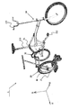
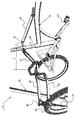
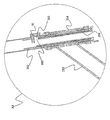
- FIG. 1 is a running view of the first embodiment of the combined moving means according to the present invention.
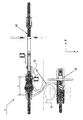
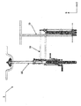
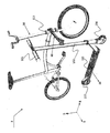
- Figures 2a to 2c is a view showing the configuration of a first embodiment of the coupling moving means according to the present invention.
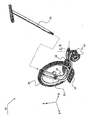
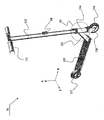
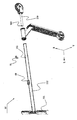
- Figure 3 is a view showing the configuration of a first embodiment of a sidecar according to the present invention.
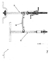
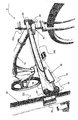
- Figures 4a to 4c is a view showing the configuration of the first embodiment of the side engaging means according to the present invention.
- FIG. 5 is a view showing a configuration of a second embodiment of the coupling moving means according to the present invention.
- 6a to 6c are views showing the configuration of the third embodiment of the coupling moving means according to the present invention.
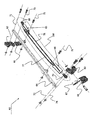
- FIG 8a to 8d are views showing the configuration of the second embodiment of the side engaging means according to the present invention.
- FIG. 9 is a view showing a configuration of a fourth embodiment of the coupling moving means according to the present invention.
- a tilting vehicle includes several multi-track vehicles from a single-track vehicle such as a two-wheeled bicycle or a motorcycle. Refers to a vehicle capable of performing a tilting operation of tilting the vehicle body in the centripetal direction to maintain balance.
- Mobility vehicle also refers to all kinds of wheeled 'means for moving or transporting', from a person traveling alone to a self-driving vehicle.
- the direction is set and displayed for easy understanding of the coupling state between the moving means and the mechanism, and the linear driving direction of the moving means is in the 'length direction', the left and right sides are in the 'lateral direction', Longitudinal direction 'and indicated as' X', 'Y' and 'Z', respectively.
- the coupling moving means proposed by the present invention is a moving means which improves transportation capacity by connecting two moving means in parallel, and specifically, the coupling moving means according to the present invention is a tilting vehicle which can tilt the vehicle body sideways when cornering and its moving means.
- the sidecars, which are means of increasing transportation capacity, are combined from each other.
- the sidecar recovers steering capability when detached from the tilting vehicle, allowing independent driving.
- Figure 1 is a running state of the first embodiment of the combined moving means according to the present invention.
- the tilting vehicle 10 for maintaining the balance by tilting the vehicle body in the centripetal force direction and the side car 20 and the tilting vehicle positioned on the side of the tilting vehicle during cornering It consists of a lateral coupling means (30, means) for mechanically connecting the sidecar.
- the side coupling means 30 provides a function of tilting the side car 20 in the same direction when the tilting vehicle 10 is inclined sideways while driving.
- the tilting vehicle 10 is depicted as a two-wheeled bicycle equipped with a pedal 112 and driven by the occupant's manpower, but all vehicles capable of only three-wheeled bicycles such as reverse three-wheeled recumbent or bellomobil as well as two-wheeled motorcycles or three-wheeled motorcycleskind can be applied.
- the sidecar is a kickboard (mini-scooter) in which a passenger pushes the ground with his feet in a standing posture.
- the main frame 21 and two front wheels 23 and one rear wheel 24 and the footrest 22 which is disposed between the front wheel and the rear wheel to firmly secure each component to each other to support the weight of the occupant It is provided.
- the sidecar 20 has a feature in which a wheelbase defined by the distance from the front wheel 23 to the rear wheel 24 is shorter than that of the tilting vehicle.
- the side car 20 the steering center line (K) of the front wheel 23 is inclined forward by ' ⁇ ', due to this structural characteristic is the main press 21 in the direction to move the weight of the occupant during independent driving At the same time as the inclination of the front wheel is shifted in the same direction to achieve steering.
- the reason why the sidecar 20 having the balance steering function of steering the weight by moving it to the left and right loses the steering ability in the state of the combined moving means of the present invention is because the wheel base is shorter than the tilting vehicle and the steering force is relatively small as described above.
- the sidecar of the present invention may be one or more of both the front wheel and the rear wheel.
- the drawings are omitted.
- the side car 20 is provided with a fixed handle 25 detachable to the main frame 21 to facilitate the balance of the occupant standing while driving. It may also provide a folding function by adding a hinge to the coupling portion of the main frame 21 and the fixed handle 25. Since the configuration of the folding handle is common in the industry, the drawings are omitted.
- the side car 20 shown in FIG. 3 is steered by the front wheel, but the present invention also steers with the rear wheel, but also presents another type of side car having a balanced steering function. If the direction of the front wheels is fixed and the rear wheels have a steering center line, tilting the steering center line to the rear allows independent driving. Since the balance steering means already exist in the prior art, the drawings are omitted.
- the main frame of the sidecar 20 21 has a predetermined length with the vibration member 40 and the first coupling link 32 positioned on the tilting vehicle 10 and the second coupling link 33 coupled to the vibration member so as not to be shaken.
- Both ends of the first coupling link and the upper coupling link 34 is coupled to each other by a longitudinal hinge on the top of the second coupling link and also has a predetermined length and both ends of the first coupling link and the second coupling link respectively. It consists of a lower connecting link 35 is coupled to the lower portion of the coupling link in the longitudinal hinge, the first coupling link is coupled to the traction bracket 31 is not coupled to the tilting vehicle (10).
- the vibration member 40 is coupled to the second coupling link 33 by a lateral hinge, so that the side car 20 can perform a relative pitching movement with respect to the tilting vehicle 10.
- the second coupling link 33 and the vibration member 40 are enlarged as illustrated in FIG. 4C. It is preferable that the shock absorbing means 41 is further provided between.
- the vibration member 40 is coupled to the second coupling link 33 by a lateral hinge to rotate back and forth relative to the center of rotation line 42 in the horizontal direction.
- the traction bracket 31 is a removable type for the purpose of being temporarily mounted on the tilting vehicle, and preferably, an anti-shake means 43 is added to secure the fixed state thereof.
- the anti-shake means one side is coupled to the traction bracket 31, the other is coupled to the other portion of the frame of the tilting vehicle 10 is not coupled to the traction bracket.
- the traction bracket 31 is fixed to the seat post 111 of the tilting vehicle 10, and the first coupling link 32 extends backward to form the traction bracket.
- the distance L from the portion where the bracket 31 is engaged with the tilting vehicle to the pivot connection portion with the other mechanical element has a length of at least 50 mm and at most 350 mm at the rear. This is to provide a free space (S1) for the pedaling of the tilting vehicle occupant.
- the tilting vehicle 10 side is convex to the rear and the side car 20 is convex to the front. It is bent to provide clearances S1 and S2 at the front and the rear, respectively.
- FIG. 5 is a view showing the configuration of a second embodiment of the coupling movement means according to the present invention.
- the tilting vehicle 11 used for the coupling moving means 2 here is a two-wheeled bicycle with a traditional diamond frame. Maintaining the basic configuration and operating mechanism of the side engaging means 30, while simply deforming the shape, the position of the traction bracket 31, which is a mechanical element for coupling the side engaging means to the tilting vehicle 11, the current position (A1) It can be understood that the following position (A2) can be changed at any time.
- the tilting vehicle frame portion included in the current position A1 is a seat tube
- the next position A2 includes 'head tube', 'front tube' and 'front tube' of the tilting vehicle.
- the coupling movement means 3 is a tilting vehicle 10 which maintains balance by tilting the vehicle body in the centripetal direction during cornering, and a side car 50 located on the side of the tilting vehicle, and mechanically connecting the tilting vehicle and the side car. It is composed of a side coupling means 60 which is a means.
- the side coupling means 60 coupled to the head tube 113 of the tilting vehicle provides a function of tilting the sidecar 50 in the same direction when the tilting vehicle 10 is inclined sideways while driving.
- the sidecar is in the form of a kickboard in which the rider pushes the ground with the foot in the standing position, It is provided with a main frame 153, one front wheel 156 and one rear wheel 157, and a footrest 155 disposed between the front wheel and the rear wheel to hold each component firmly to secure each component.
- the sidecar 50 has a feature in which the wheelbase defined by the distance from the front wheel 156 to the rear wheel 157 is shorter than the wheelbase of the tilting vehicle.
- the side car 50 is steered by changing the direction of travel of the front wheel, the head tube 154 and the passenger to provide a steering center line of the front wheel 156 to the front portion of the main frame 153 can be operated by the passenger by hand
- the kickboard handle pillar 152 of this shape has a function of reducing the volume by being hinged to the bottom portion and lying down close to the footrest 155.
- the side car 50 further includes a steering mode converting means 90 at the display portion A3 of the handle column, wherein the steering mode converting means is between the steering wheel 151 and the front wheel.
- the steering mode converting means is between the steering wheel 151 and the front wheel.
- the steering mode converting means is at least longer than the length of the steering center line direction of the head tube 154 and the fork 158.
- Rotating member 159 connected to the upper end of the locking member 91 and the role of selectively permitting or blocking the rotation of the rotating member relative to the handle pillar of the rotation member 159, the upper portion of the locking member Groove 160 is formed, the rotating member 159 is coupled inward from the lower portion of the handle pillar 152, the locking groove in the state in which the rotating member 159 and the handle pillar 152 is coupled
- An insertion hole 161 is formed at a portion of the handle pillar 152 contacted with the insertion hole, and the insertion hole 161 extends upward.
- the locking member 91 is lifted up to remove the balance control ability of the sidecar 50, and vice versa.
- the locking member 91 is lowered to restore the balance control ability, thereby enabling independent driving.
- the present invention also includes a sidecar having such a configuration.
- Various prior arts appear, so drawings are omitted.
- the side engagement means is located on the side car 50 side
- Both ends of the first coupling link 62 positioned on the side of the vibrating member 67 and the tilting vehicle 10 and the second coupling link 63 coupled to the vibrating member 67 have predetermined lengths.
- the horizontal coupling link 64 and the first coupling link 62 and the second coupling link 63 which are coupled to the upper portion of the first coupling link 62 and the second coupling link 63 by a longitudinal hinge. It consists of a hydraulic system (160, coupled to the bottom of the).
- the vibration member 67 is coupled to the towing bracket 68 coupled so as not to shake to the handle pillar 152 of the side car 50
- the first coupling link 62 is the head tube of the tilting vehicle ( 113 is coupled to the traction bracket 61 is coupled to not shake.
- the coupling method of the vibration member 67 and the towing bracket 68 will not be too large for welding or other fixing methods.
- the vibrating member 92 and the first coupling link 62 are provided with an embossed groove in common, and on the contrary, the towing bracket 68 and the traction bracket 61 are provided with an intaglio recess. It was easy to separate.
- the hydraulic device 160 connects two double-acting cylinders 65 and 66 and two double-acting cylinders coupled to the left and right sides of the horizontal link 64 by longitudinal hinges, respectively, to form a hydraulic circuit. It consists of two pipes (77, 78), the end of the piston rod (69, 70) of each double-acting cylinder with a longitudinal hinge to the first coupling link 62 and the second coupling link (63), respectively Combined.
- the six center of rotation lines 71, 72, 73, 74, 75, and 76 are the criteria for the relative pivot movement of the members joined to each other.
- the left port (82, port) of the right double-acting cylinder 66 is connected to the right port 81 of the left double-acting cylinder (65) and the right double-acting cylinder (
- the right port 84 of 66 is connected to the left port 83 of the left double-acting cylinder 65, so that the hydraulic device 160 transmits the tilting motion between the tilting vehicle and the sidecar. Take it.
- the hydraulic conduit for connecting two double-acting cylinders in the hydraulic device 160 of the side coupling device 60 of the present invention is connected to the ports of the symmetrical position.
- the vibration member 67 is coupled to the second coupling link 63 by a lateral hinge so that the pivot member can pivot based on the lateral steering center line 79, thereby allowing the side car 50 to tilt the vehicle.
- Relative pitching can be performed with respect to (10).
- a buffer means is added between the second coupling link and the vibration member in order to alleviate the sudden shaking when the sidecar makes a pitching motion relative to the tilting vehicle.
- FIG. 9 is a view showing a configuration of a fourth embodiment of the coupling moving means according to the present invention.
- Two side cars 20 and 50 may be connected to one tilting vehicle 10. It is also possible to connect two or more sidecars by utilizing both the left and right spaces of the tilting vehicle.
- the above description is based on the embodiment of the coupling movement means according to the present invention, but includes a description of the components of the coupling movement means.
- the link device used as the side coupling means and the kick board used as the sidecar may be briefly described as follows, and the detailed description thereof will be omitted since it is duplicated with the above.
- 4A to 4C are means for connecting a sidecar to the tilting vehicle, the first coupling link coupled to the tilting vehicle so as not to be shaken and the vibration member coupled to the sidecar so as not to shake the side of the vibration member
- Both ends have a predetermined length and a second coupling link coupled to the directional hinge, and both ends have a predetermined length and an upper connection link coupled to the top of the first coupling link and the second coupling link by a longitudinal hinge, respectively.
- the sidecar can be a relative pitching movement with respect to the tilting vehicle.
- the tilting vehicle is provided with a towing bracket having a recessed groove
- the sidecar is provided with a towing bracket provided with a recessed groove
- the embossed groove is provided in common to the vibration member and the first coupling link.
- 8A to 8D are also means for connecting the sidecar to the tilting vehicle, the first coupling link coupled to the tilting vehicle so as not to shake the vibration member and the vibration member coupled to the sidecar so as not to shake
- a horizontal coupling link having a predetermined length and a second coupling link coupled to a lateral hinge, and both ends of which are coupled by a longitudinal hinge to one of the upper and lower portions of the first coupling link and the second coupling link, respectively;
- the first coupling link and the upper or lower portion of the second coupling link of the hydraulic device is coupled to the other portion of the coupling portion that is not coupled to the horizontal link, each of the longitudinal hinges on the left and right of the horizontal link
- the end of the piston rod of each double-acting cylinder is coupled to the first coupling link and the second coupling link in the longitudinal hinge, respectively, and in particular in the configuration of the hydraulic circuit, the hydraulic pipe
- the tilting vehicle is provided with a traction bracket having an intaglio recess
- the sidecar is provided with a towing bracket having an intaglio recess
- the embossed recess is common to the vibration member and the first coupling link. It is provided, the vibration member and the groove of the towing bracket is engaged with each other and firmly fixed, and the groove of the first coupling link and the towing bracket is securely engaged with each other. This makes it possible to easily attach and detach the link device.
- the kickboard shown in FIG. 3 is connected to the side of an independent vehicle and another vehicle, and is a vehicle capable of passive driving.
- the kickboard is a shape of a kickboard in which a passenger pushes the ground with his feet in a standing position.
- a mainframe for firmly fixing each component, one or more front wheels, one or more rear wheels, and two footrests arranged between the front wheels and the rear wheels to support the weight of the occupant and fixed to the mainframe.
- the mainframe is divided into two left and right, the rear wheel is located therebetween, the footrest is also coupled to the outside of the mainframe divided into left and right, but the mainframe is inclined in the direction to move the weight of the occupant At the same time as the load, the driving direction of the front wheel Twisted the steering features a yirwojim.
- the kickboard is inclined forward of the steering center line of the front wheel.
- kickboards which are connected to the side of another vehicle and are capable of passive driving, which are also connected to the side of another vehicle, in the shape of a kickboard in which a passenger pushes the ground with his feet in a standing position.
- a mainframe and one or more front wheels and one or more rear wheels and a footrest disposed between the front wheels and the rear wheels to hold the weight of the occupant and providing a steering centerline of the front wheels to the front part of the mainframe.
- a steering wheel that can be operated by the passenger by hand, a fork supporting the front wheel, and a handle column connecting the steering wheel from the top to the fork, wherein a lower portion of the handle column rotates inside the head tube.
- the steering column additional to the steering mode conversion means
- the steering mode conversion means by connecting or disconnecting the mechanical connection state between the steering wheel and the front wheel to perform the function of allowing or blocking the transmission of the steering force applied to the steering wheel to the front wheel.
- the steering mode converting means is a lock that selectively permits or blocks a relative rotation of the rotating member connected to the top of the fork and the handle column of the rotating member at least longer than a steering center line length of the head tube.
- the upper portion of the rotating member is formed with a locking groove
- the rotating member is coupled inward from the lower portion of the handle pillar, the contact with the locking groove in the state in which the rotating member and the handle pillar is coupled
- An insertion hole is formed in a portion of the handle pillar, and the insertion hole has a shape extending upward, and when the locking member is inserted into the insertion hole and lowered, the handle pillar and the rotating member are fixed to each other. When lifted up, the fixing state is released and the top of the rotating member relative to the handle column It has a characteristically capable of rotational movement.
- the kickboard is a manpower transport means further comprising a maneuvering drive device is provided with a saddle for the occupant to sit, a pedal for the occupant to move the foot and a crank for power transmission.
Landscapes
- Engineering & Computer Science (AREA)
- Mechanical Engineering (AREA)
- Transportation (AREA)
- Automatic Cycles, And Cycles In General (AREA)
Abstract
La présente invention porte sur des moyens de transport accouplés, lesquels moyens sont un accouplement latéral d'un véhicule à inclinaison, ayant une fonction d'inclinaison permettant à une caisse de véhicule d'être inclinée latéralement pendant un virage, avec un side-car qui joue le rôle de moyens pour accroître la capacité de transport du véhicule à inclinaison. Contrairement à des side-car classiques, le side-car selon la présente invention est, de façon caractéristique, apte à être entraîné indépendamment quand il est séparé du véhicule à inclinaison. Le side-car comprend une ou plusieurs roues avant et une ou plusieurs roues arrière, et non une roue unique classique. Également, pour permettre à une aptitude de commande à la direction d'être exercée de façon sélective, le side-car per se joue le rôle de moyens de transport aptes à une direction d'équilibrage, ou comprend des moyens de conversion de mode de direction tels qu'un utilisateur peut sélectionner, par une opération simple, s'il faut ou non permettre à une force de direction appliquée à une roue de direction d'être transmise. De plus, des moyens d'accouplement latéral sont basés sur une liaison à parallélogramme, et un élément de vibration est de plus disposé sur le côté side-car, de telle sorte que le side-car peut effectuer un mouvement d'inclinaison longitudinale par rapport au véhicule à inclinaison, l'élément de vibration étant accouplé de façon articulée latéralement à la liaison à parallélogramme.
Applications Claiming Priority (2)
| Application Number | Priority Date | Filing Date | Title |
|---|---|---|---|
| KR10-2014-0059470 | 2014-05-19 | ||
| KR1020140059470A KR101518671B1 (ko) | 2014-05-19 | 2014-05-19 | 결합이동수단과 그것의 측면결합수단 용도의 링크장치와 사이드카 용도의 킥보드 |
Publications (1)
| Publication Number | Publication Date |
|---|---|
| WO2015178652A1 true WO2015178652A1 (fr) | 2015-11-26 |
Family
ID=53394203
Family Applications (1)
| Application Number | Title | Priority Date | Filing Date |
|---|---|---|---|
| PCT/KR2015/004980 Ceased WO2015178652A1 (fr) | 2014-05-19 | 2015-05-18 | Moyens de transport accouplés |
Country Status (2)
| Country | Link |
|---|---|
| KR (1) | KR101518671B1 (fr) |
| WO (1) | WO2015178652A1 (fr) |
Families Citing this family (1)
| Publication number | Priority date | Publication date | Assignee | Title |
|---|---|---|---|---|
| CN113212623B (zh) * | 2021-04-07 | 2023-06-20 | 美棒技术(上海)有限公司 | 一种模块车 |
Citations (11)
| Publication number | Priority date | Publication date | Assignee | Title |
|---|---|---|---|---|
| JPS5257014Y2 (fr) * | 1975-04-19 | 1977-12-23 | ||
| US4385770A (en) * | 1981-02-06 | 1983-05-31 | Mitchell Wallace F | Motorcycle sidecar |
| JPH0592789A (ja) * | 1991-06-19 | 1993-04-16 | Honda Motor Co Ltd | 複合二輪車 |
| KR200287307Y1 (ko) * | 2002-04-17 | 2002-08-30 | 김양욱 | 레저커플자전거 |
| KR20030040905A (ko) * | 2001-11-17 | 2003-05-23 | 권병하 | 평행연결자전거용 자전거 |
| US20040026889A1 (en) * | 2002-05-15 | 2004-02-12 | Foley Michael John | Bicycle sidecar |
| KR200342492Y1 (ko) * | 2003-08-18 | 2004-02-18 | 구자윤 | 조인트를 구비한 킥보드 |
| KR100894418B1 (ko) * | 2008-09-04 | 2009-04-24 | 김홍기 | 킥보드 |
| WO2009149653A1 (fr) * | 2008-06-10 | 2009-12-17 | Chin Hsu-Sheng | Vélo à double cadre |
| KR20100098877A (ko) * | 2009-03-02 | 2010-09-10 | 성민경 | 수동 킥보드 |
| KR101074040B1 (ko) * | 2010-06-29 | 2011-10-17 | 김성식 | 다인용 자전거 |
-
2014
- 2014-05-19 KR KR1020140059470A patent/KR101518671B1/ko not_active Expired - Fee Related
-
2015
- 2015-05-18 WO PCT/KR2015/004980 patent/WO2015178652A1/fr not_active Ceased
Patent Citations (11)
| Publication number | Priority date | Publication date | Assignee | Title |
|---|---|---|---|---|
| JPS5257014Y2 (fr) * | 1975-04-19 | 1977-12-23 | ||
| US4385770A (en) * | 1981-02-06 | 1983-05-31 | Mitchell Wallace F | Motorcycle sidecar |
| JPH0592789A (ja) * | 1991-06-19 | 1993-04-16 | Honda Motor Co Ltd | 複合二輪車 |
| KR20030040905A (ko) * | 2001-11-17 | 2003-05-23 | 권병하 | 평행연결자전거용 자전거 |
| KR200287307Y1 (ko) * | 2002-04-17 | 2002-08-30 | 김양욱 | 레저커플자전거 |
| US20040026889A1 (en) * | 2002-05-15 | 2004-02-12 | Foley Michael John | Bicycle sidecar |
| KR200342492Y1 (ko) * | 2003-08-18 | 2004-02-18 | 구자윤 | 조인트를 구비한 킥보드 |
| WO2009149653A1 (fr) * | 2008-06-10 | 2009-12-17 | Chin Hsu-Sheng | Vélo à double cadre |
| KR100894418B1 (ko) * | 2008-09-04 | 2009-04-24 | 김홍기 | 킥보드 |
| KR20100098877A (ko) * | 2009-03-02 | 2010-09-10 | 성민경 | 수동 킥보드 |
| KR101074040B1 (ko) * | 2010-06-29 | 2011-10-17 | 김성식 | 다인용 자전거 |
Also Published As
| Publication number | Publication date |
|---|---|
| KR101518671B1 (ko) | 2015-05-07 |
Similar Documents
| Publication | Publication Date | Title |
|---|---|---|
| US20090289437A1 (en) | Vehicle with three wheels | |
| US20040056452A1 (en) | Folding bicycle | |
| US6659488B1 (en) | Tricycle | |
| CZ300657B6 (cs) | Univerzální skládací jízdní kolo | |
| WO2013154356A2 (fr) | Cadre de bicyclette et bicyclette ainsi que voiture d'enfant qui utilise ce dernier qui permet une conversion de deux roues à trois roues et inversement | |
| WO2010147310A2 (fr) | Dispositif de déplacement actionné manuellement | |
| WO2021256666A1 (fr) | Système de châssis avant de véhicule inclinable | |
| KR100931524B1 (ko) | 삼륜 자전거 | |
| US8123242B2 (en) | Folding steering column for elliptical bike and method of use | |
| US10759486B2 (en) | Three or four wheeled human powered vehicle with dual wheel front steering and single or dual wheel rear drive | |
| WO2015178652A1 (fr) | Moyens de transport accouplés | |
| US20080296862A1 (en) | Multi-mode tandem bicycle | |
| AU2003296681B2 (en) | Folding bicycle | |
| KR101608187B1 (ko) | 결합이동수단 구성을 위한 킥보드 형상의 사이드카 | |
| KR101608186B1 (ko) | 결합이동수단의 측면결합을 위한 링크장치 | |
| CN1042815C (zh) | 两用车 | |
| GB2289874A (en) | Folding bicycle | |
| RU2158212C1 (ru) | Грузовой велосипед повышенной грузоподъемности | |
| JP2005119450A (ja) | 前二輪後一輪の三輪車 | |
| IT1289193B1 (it) | Bicicletta comportante mezzi per rendere motrice anche la ruota anteriore | |
| RU226830U1 (ru) | Складной велосипед | |
| RU2000245C1 (ru) | Велосипед Грызлова | |
| RU77826U1 (ru) | Узел сцепки для легких колесных транспортных средств | |
| WO2020091236A1 (fr) | Tricycle inversé comprenant trois parties d'entraînement, et réalisation d'une fonction d'inclinaison selon un angle naturel simultanément à la direction | |
| RU2083425C1 (ru) | Сдвоенный велосипед |
Legal Events
| Date | Code | Title | Description |
|---|---|---|---|
| 121 | Ep: the epo has been informed by wipo that ep was designated in this application |
Ref document number: 15796865 Country of ref document: EP Kind code of ref document: A1 |
|
| NENP | Non-entry into the national phase |
Ref country code: DE |
|
| 122 | Ep: pct application non-entry in european phase |
Ref document number: 15796865 Country of ref document: EP Kind code of ref document: A1 |