WO2015181908A1 - Pompe ou moteur à engrenages - Google Patents
Pompe ou moteur à engrenages Download PDFInfo
- Publication number
- WO2015181908A1 WO2015181908A1 PCT/JP2014/064132 JP2014064132W WO2015181908A1 WO 2015181908 A1 WO2015181908 A1 WO 2015181908A1 JP 2014064132 W JP2014064132 W JP 2014064132W WO 2015181908 A1 WO2015181908 A1 WO 2015181908A1
- Authority
- WO
- WIPO (PCT)
- Prior art keywords
- gear
- gears
- slidability
- side surfaces
- hydraulic pressure
- Prior art date
- Legal status (The legal status is an assumption and is not a legal conclusion. Google has not performed a legal analysis and makes no representation as to the accuracy of the status listed.)
- Ceased
Links
Images




Classifications
-
- F—MECHANICAL ENGINEERING; LIGHTING; HEATING; WEAPONS; BLASTING
- F04—POSITIVE - DISPLACEMENT MACHINES FOR LIQUIDS; PUMPS FOR LIQUIDS OR ELASTIC FLUIDS
- F04C—ROTARY-PISTON, OR OSCILLATING-PISTON, POSITIVE-DISPLACEMENT MACHINES FOR LIQUIDS; ROTARY-PISTON, OR OSCILLATING-PISTON, POSITIVE-DISPLACEMENT PUMPS
- F04C2/00—Rotary-piston machines or pumps
- F04C2/08—Rotary-piston machines or pumps of intermeshing-engagement type, i.e. with engagement of co-operating members similar to that of toothed gearing
- F04C2/12—Rotary-piston machines or pumps of intermeshing-engagement type, i.e. with engagement of co-operating members similar to that of toothed gearing of other than internal-axis type
- F04C2/14—Rotary-piston machines or pumps of intermeshing-engagement type, i.e. with engagement of co-operating members similar to that of toothed gearing of other than internal-axis type with toothed rotary pistons
- F04C2/18—Rotary-piston machines or pumps of intermeshing-engagement type, i.e. with engagement of co-operating members similar to that of toothed gearing of other than internal-axis type with toothed rotary pistons with similar tooth forms
Definitions
- the present invention relates to a gear pump or a motor used for an industrial machine or the like.
- hydraulic pressure acts toward the side surface of the gear.
- the size of the region where the hydraulic pressure acts is usually determined by the rotation angle of the gear with respect to the body and the seal length of the side plate that slides over the region from the bottom of the gear toward the shaft center. Determined by both.
- the rotation angle of the gear periodically changes from moment to moment, and the seal length is determined by the seal length corresponding to the difference between the tooth root diameter of the gear and the hole diameter provided in the side plate. That is, the region where the hydraulic pressure acts when the gears have the same shape is determined by the seal length.
- the hydraulic pressure acting in the direction opposite to the hydraulic pressure on the non-sliding surface, which is the back side of the sliding surface of the side plate, is determined by the shape of the three-shaped gasket that partitions the high and low pressures.
- the hydraulic pressure is balanced by appropriately adjusting the seal length and the shape of the gasket so that the side plate is pressed against the gear with an appropriate force so that the internal pressure from the side of the gear can be reduced. Leakage is suppressed.
- the hydraulic gear pump or motor described in Patent Document 1 has the gear sandwiched between side plates having the same shape, so that the hydraulic pressure acting on both side surfaces of the gear is reduced between the front side and the rear side. Equal on the side.
- the hydraulic pressure from the side plates acting in the axial direction against the gear cancels out, and the gear is in a mechanically neutral state in the axial direction.
- the present invention focuses on such problems, and provides a gear pump or motor that can effectively ensure mechanical efficiency and durability even when materials having different slidability are used on both sides of the gear.
- the purpose is to do.
- the gear pump or motor according to the present invention includes a gear pair meshed with each other, a housing structure having a gear housing chamber for housing the gear pair, and one side plate housed in the gear housing chamber.
- the hydraulic pressure acts on the side surface of the gear having the lower slidability.
- the area is made larger than the area of the hydraulic pressure acting on the side surface of the gear having the higher slidability.
- the gear pump or motor according to the present invention has a gear pair meshed with each other and a gear storage chamber for storing the gear pair inside, and slides on both side surfaces of the gear pair inside the gear storage chamber.
- a gear pump or a motor having a housing structure in contact therewith, and a hydraulic pressure acting on a side surface of the gear having the lower slidability among the slidability between the gear pair and the housing structure.
- the working area is larger than the working area of the hydraulic pressure acting on the side surface of the gear having the higher slidability.
- the gear pump or motor according to the present invention includes a gear pair meshed with each other, a housing structure having a gear housing chamber for housing the gear pair therein, and the gear pair inside the gear housing chamber.
- a gear pump or motor comprising two side plates arranged so as to be in sliding contact with both side surfaces, the gear having the lower sliding property among the sliding properties between the gear pair and the two side plates.
- the working area of the hydraulic pressure acting on the side surface of the gear is made larger than the working area of the hydraulic pressure acting on the side surface of the gear having the higher slidability.
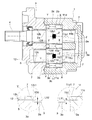
- the gear pump drives the hydraulic fluid introduced from the suction port when the drive gear 2 and the driven gear 3 are driven via the drive shaft 4 having one end extended to the outside.
- a pumping action is performed in which a volume space closed between the tooth tips of the gear 2 and the driven gear 3 and the inner periphery of the housing structure 1 is confined to the discharge port and discharged to the discharge port.
- this gear pump is a gear motor that operates as a motor that introduces a high-pressure hydraulic fluid, extracts rotational torque from the drive shaft 4 to drive an external load, and discharges the hydraulic fluid at a low pressure. Needless to say, it can also function.
- the gear pump according to the present embodiment mainly includes a housing structure 1 having a gear housing chamber 11a therein, and an external gear pair that is housed and held in the gear housing chamber 11a of the housing structure 1 and is engaged with each other, that is, The driving gear 2 and the driven gear 3 are provided, and in this embodiment, one side plate 6 that is in contact with the front side of the gears 2 and 3 is provided. That is, the gear pump according to the present embodiment includes gears 2 and 3, a housing structure 1 having a gear housing chamber 11 a for housing the gears 2 and 3 therein, and one housing housed in the gear housing chamber 11 a.
- a side plate 6, one side surface 2 a, 3 a of the gear 2, 3 is in sliding contact with the body 11 of the housing structure 1 inside the gear housing chamber 11 a, and the other side surface 2 a, 3 a is in contact with the side plate 6.
- the housing structure 1 and the side plate 6 have sliding surfaces 11d and 6d that are in sliding contact with the side surfaces 2a and 3a of the gears 2 and 3 from the front side and the rear side, respectively, inside the gear housing chamber 11a. is doing.
- the driving gear 2 and the driven gear 3 are well-known gears in which a plurality of tooth bodies are provided radially at predetermined intervals from the tooth bottoms 2b and 3b toward the tooth tips 2c and 3c, that is, the outer peripheral surface.
- the drive shaft 4 is integrally extended from the center of the drive gear 2 in the rotational axis direction
- the driven shaft 5 is integrally extended from the driven gear 3 in the rotational axis direction.
- the drive gear 2 and the drive shaft 4 may be configured separately, and the driven gear 3 and the driven shaft 5 may be configured separately.
- the housing structure 1 includes, for example, a body 11 having the gear housing chamber 11a and a front cover 12 serving as a cover for closing the opening surface of the gear housing chamber 11a.
- a body 11 having the gear housing chamber 11a and a front cover 12 serving as a cover for closing the opening surface of the gear housing chamber 11a.
- the rear side of the body 11 alone can be closed, but of course, the rear side of the body 11 may be opened and closed with a separate rear cover.
- the body 11 is made of, for example, cast iron in this embodiment.
- the body 11 is connected to the gear pair, that is, the drive gear 4 and the driven shaft 5 in communication with the rear side of the gear storage chamber 11a.
- Bearing holes 11b and 11c are formed.
- a bush 7 is fitted in the bearing hole 11b near the position where the drive gear 2 is to be inserted, and one end of the drive shaft 4 is inserted into the bush 7 so as to be rotatably supported.
- a bush 7 is fitted into the bearing hole 11c near the position where the driven gear 3 is to be inserted, and one end of the driven shaft 5 is inserted into the bush 7 so as to be rotatably supported.
- the body 11 has a suction (not shown) at a predetermined position on the tangential side of the meshing pitch circle between the driving gear 2 and the driven gear 3, that is, at a position facing the meshing pitch circle between the driving gear 2 and the driven gear 3.
- the mouth and the discharge port are opened.
- the body 11 is provided with a sliding surface 11d that is in sliding contact with the rear side surfaces 2a and 3a of the gears 2 and 3.
- the area where the sliding surface 11d is in sliding contact with the side surfaces 2a and 3a, that is, the working area of the hydraulic pressure pressing the side surfaces 2a and 3a from the sliding surface 11d side is determined by the setting of the diameters of the bearing holes 11b and 11c.
- the seal length L11 which is the distance from the end portions 11b1 and 11c1 of the bearing holes 11b and 11c to the tooth bottoms 2b and 3b.
- the high-pressure hydraulic fluid in the gear housing chamber 11a always flows into the gap between the sliding surface 11d and the side surfaces 2a and 3a, thereby causing the sliding surface 11d and the side surface 2a.
- the acting force that tries to separate 3a that is, the acting force that presses the side surfaces 2a and 3a is always working.
- the magnitude of this acting force is proportional to the area where the sliding surface 11d and the side surfaces 2a, 3a are in sliding contact. In this embodiment, such an area is proportional to the size of the annular region (not shown) as viewed from the side with the dimension of the seal length L11 as the thickness. In other words, the longer the seal length L11, the greater the acting force that presses the side surfaces 2a, 3a generated by the hydraulic fluid in the gear housing chamber 11a to the front side.
- the front cover 12 is detachably mounted on the body 11 with bolts or the like, for example, and closes the front opening surface of the gear housing chamber 11a, for example, made of aluminum die cast.
- the drive shaft 4 and the driven shaft 5 are Bearing holes 12b and 12c that can be respectively inserted are formed.
- a bush 7 is fitted into the bearing hole 12b near the position where the drive gear 2 is to be inserted, and one end of the drive shaft 4 is inserted into the bush 7 so as to be rotatably supported.
- a bush 7 is fitted into the bearing hole 12c near the position where the driven gear 3 is to be inserted, and one end of the driven shaft 5 is inserted into the bush 7 so as to be rotatably supported.
- the side plate 6 is a plate-like plate made of an appropriate material excellent in corrosion resistance, strength, and wear resistance, such as lead or lead bronze casting, and the drive shaft 4 and the driven shaft 5 can be inserted respectively. Bearing holes 6b and 6c are formed.
- the drive gear 2 and the driven gear 3 are arranged so as to contact the front side surfaces 2 a and 3 a and seal the side surfaces 2 a and 3 a of the drive gear 2 and the driven gear 3. Is for.
- the non-sliding surface 6e of the side plate 6 is provided with a gasket groove 6f, and the gasket 8 is fitted into the gasket groove 6f.
- the side plate 6 is formed with a sliding surface 6d that is in sliding contact with the front side surfaces 2a and 3a of the gears 2 and 3.
- the area where the sliding surface 6d is in sliding contact with the side surfaces 2a and 3a, that is, the working area of the hydraulic pressure that presses the side surfaces 2a and 3a from the sliding surface 6d side, is the dimension setting of the diameter ⁇ S of the bearing holes 6b and 6c shown in FIG. It depends on. In other words, it is determined by the seal length L6, which is the distance from the end portions 6b1 and 6c1 of the bearing holes 6b and 6c to the tooth bottoms 2b and 3b, as shown by enlarging the I portion in FIG.
- the high-pressure hydraulic fluid in the gear housing chamber 11a always flows into the gap between the sliding surface 6d and the side surfaces 2a and 3a, thereby causing the sliding surface 6d and the side surface 2a.
- the acting force that tries to separate 3a that is, the acting force that presses the side surfaces 2a and 3a is always working.
- the magnitude of this acting force is proportional to the area where the sliding surface 6d and the side surfaces 2a, 3a are in sliding contact. In this embodiment, such an area is proportional to the size of an annular region in a side view (not shown) with the dimension of the seal length L6 as the thickness. In other words, the longer the seal length L6, the greater the acting force that presses the side surfaces 2a, 3a generated by the hydraulic fluid in the gear housing chamber 11a to the rear side.
- the gear pump or motor has the gears 2 and 3 meshing with each other as described above, and the gear housing chamber 11a for housing the gears 2 and 3 inside, and the inside of the gear housing chamber 11a.
- the gear pump or motor is configured to be in sliding contact with both side surfaces 2a and 3a of the gears 2 and 3, respectively, and the slidability between the gears 2 and 3 and the body 11, and the gears 2, 3 and the side plate 6 Of the slidability between the two, the working area of the hydraulic pressure acting on the side surfaces 2a and 3a of the gears 2 and 3 facing the body 11, which is the lower slidability, is the side plate having the higher slidability.
- the seal length L11 that determines the working area of the hydraulic pressure acting on one side 2a, 3a of the gears 2, 3 from one sliding surface 11d side is set to the other. It was made larger than the seal length L6 which determines the action
- the hydraulic pressure X which is an action force that presses the side surfaces 2 a and 3 a of the gears 2 and 3 from the sliding surface 11 d side of the body 11 to the front side, is the sliding surface of the side plate 6. It becomes larger than the hydraulic pressure Y, which is the acting force that presses the side surfaces 2a, 3a of the gears 2, 3 from the 6d side to the rear side.
- the gears 2 and 3 are biased by the difference Z between the acting forces of the hydraulic pressure X and the hydraulic pressure Y.
- friction generated from the body 11 having low slidability is reduced.
- the gears 2 and 3 are of the same shape or symmetrical shape on both sides.
- the configuration according to the present embodiment is realized without changing the shape of the gear, including the dimensions of the tooth bottom and the tooth tip. That is, as shown in FIG. 2, in this embodiment, as shown in an enlarged view in FIG. 1, only the diameter ⁇ B of the bearing holes 11b and 11c is made smaller than the diameter ⁇ S of the bearing holes 6b and 6c.
- the length L11 larger than the seal length L6, the working area on which the hydraulic pressure acts is increased.
- a force Z that urges toward the side plate 6 is generated, so that the problem is that seizure is likely to occur on one sliding surface 11d having low slidability. It is effectively suppressed.
- the decrease in mechanical efficiency caused by the sliding performance of the sliding surface 11d of the body 11 when the sliding surface 6d of the side plate 6 is lowered is also suppressed.
- mechanical efficiency and durability can be effectively secured even when materials having different slidability are used for both sides 2a and 3a of the gears 2 and 3, respectively. For this reason, a gear pump or motor that effectively improves the degree of freedom in designing the sliding surface is realized.
- the gears since the mechanical efficiency and durability are the same as those of the prior art without providing a side plate on the rear side, that is, on the body 11 side, the gears have the same thickness as that of the side plate that does not require at least a gear pump or motor. It is made compact in the axial direction.
- the gear pump according to the present embodiment includes gears 2 and 3, a housing structure 1 having a gear housing chamber 11 a for housing the gears 2 and 3 therein, and one housing housed in the gear housing chamber 11 a.
- side surfaces 2a and 3a of the gears 2 and 3 are in sliding contact with the front cover 12 of the housing structure 1, and the other side surfaces 2a and 3a are in contact with the side plate 6.
- the housing structure 1 and the side plate 6 are provided with sliding surfaces 12d and 6d in sliding contact with the side surfaces 2a and 3a of the gears 2 and 3 from the front side and the rear side, respectively, inside the gear housing chamber 11a. It is.
- the front cover 12 is formed with a sliding surface 12d that is in sliding contact with the front side surfaces 2a and 3a of the gears 2 and 3.
- the area where the sliding surface 12d is slidably in contact with the side surfaces 2a and 3a, that is, the working area of the hydraulic pressure that presses the side surfaces 2a and 3a from the sliding surface 12d side is the dimension setting of the diameter ⁇ B of the bearing holes 12b and 12c shown in FIG.
- the seal length L12 which is the distance from the ends 12b1 and 12c1 of the bearing holes 12b and 12c to the tooth bottoms 2b and 3b as shown in an enlarged view of the portion III in FIG.
- the high-pressure hydraulic fluid in the gear housing chamber 11a always flows into the gap between the sliding surface 12d and the side surfaces 2a and 3a, so that the sliding surface 12d and the side surface 2a.
- the acting force that tries to separate 3a that is, the acting force that presses the side surfaces 2a and 3a is always working.
- the magnitude of this acting force is proportional to the area where the sliding surface 12d and the side surfaces 2a, 3a are in sliding contact. In this embodiment, such an area is proportional to the size of an annular region in a side view (not shown) with the dimension of the seal length L12 as a thickness. In other words, the longer the seal length L12, the greater the acting force for pressing the side surfaces 2a, 3a generated by the hydraulic fluid in the gear housing chamber 11a to the rear side.
- the side plate 6 has a symmetrical shape with the first embodiment, and forms a sliding surface 6d that is in sliding contact with the rear side surfaces 2a and 3a of the gears 2 and 3.
- the area where the sliding surface 6d is in sliding contact with the side surfaces 2a and 3a, that is, the working area of the hydraulic pressure pressing the side surfaces 2a and 3a from the sliding surface 6d side, is the dimension setting of the diameter ⁇ S of the bearing holes 6b and 6c shown in FIG. It depends on. In other words, it is determined by the seal length L6, which is the distance from the end portions 6b1 and 6c1 of the bearing holes 6b and 6c to the tooth bottoms 2b and 3b, as shown by enlarging the IV portion in FIG.
- the high-pressure hydraulic fluid in the gear housing chamber 11a always flows into the gap between the sliding surface 6d and the side surfaces 2a and 3a, thereby causing the sliding surface 6d and the side surface 2a.
- the acting force that tries to separate 3a that is, the acting force that presses the side surfaces 2a and 3a is always working.
- the magnitude of this acting force is proportional to the area where the sliding surface 6d and the side surfaces 2a, 3a are in sliding contact. In this embodiment, such an area is proportional to the size of an annular region in a side view (not shown) with the dimension of the seal length L6 as the thickness. In other words, the longer the seal length L6, the greater the acting force that presses the side surfaces 2a, 3a generated by the hydraulic fluid in the gear housing chamber 11a to the front side.
- the gear pump or motor according to the present embodiment has a slidability among the slidability between the gears 2, 3 and the front cover 12 and the slidability between the gears 2, 3 and the side plate 6.
- the side surface 2a of the gears 2 and 3 facing the side plate 6 having the higher slidability is the same as the area of the hydraulic pressure acting on the side surfaces 2a and 3a of the gears 2 and 3 facing the front cover 12 which is the lower side. It was made larger than the working area of the hydraulic pressure acting on 3a.
- the slidability of one sliding surface 12d on the front side that is in sliding contact with the one side surfaces 2a and 3a of the gears 2 and 3, that is, the slidability of the aluminum die cast is the same as that of the other sliding surface 6d on the rear side.
- Slidability that is, the working area of the hydraulic pressure acting on one side 2a, 3a of the gears 2, 3 from one sliding surface 12d side under the situation that it is lower than the material such as lead or lead bronze casting
- the seal length L12 is made larger than the seal length L6 that determines the action area of the hydraulic pressure acting on the side surfaces 2a and 3a of the gears 2 and 3 from the other sliding surface 6d side.
- the hydraulic pressure X which is an action force that presses the side surfaces 2 a and 3 a of the gears 2 and 3 from the sliding surface 12 d side of the front cover 12 to the rear side, causes the sliding of the side plate 6. It becomes larger than the hydraulic pressure Y which is an acting force for pressing the side surfaces 2a and 3a of the gears 2 and 3 from the surface 6d side to the front side.
- the gears 2 and 3 are biased by the difference Z between the acting forces of the hydraulic pressure X and the hydraulic pressure Y.
- friction generated from the front cover 12 having low slidability is reduced.
- the seal length L12 is set to the seal length only by making the diameter ⁇ F of the bearing holes 12b and 12c smaller than the diameter ⁇ S of the bearing holes 6b and 6c. By making it larger than L6, the working area where the hydraulic pressure acts is increased.
- the side plate 6 is provided only on one of the front side and the rear side, and the gear pump or the motor configured compactly by disposing the side plate 6 is not provided on the other side. It is good also as an aspect which does not provide the side plate 6 in both sides. In other words, the housing structure 1 may be configured without the side plate 6.
- the gear pump or motor has gears 2 and 3 and a gear storage chamber 11a for storing the gears 2 and 3 therein, and a gear inside the gear storage chamber 11a.
- the housing structure 1 is provided with sliding surfaces 12d and 11d which are in sliding contact with the two side surfaces 2a and 3a, respectively.
- the gear pump is configured such that sliding surfaces 11d and 12d are formed on the body 11 and the front cover 12 constituting the housing structure 1, respectively. Then, as shown in an enlarged view in FIG. 5, by setting the seal length L11 to be larger than the seal length L12, a force Z for urging the gears 2 and 3 near the front cover 12 is generated during operation. I am doing so.
- the front cover 12 is formed with a sliding surface 12d that is in sliding contact with the front side surfaces 2a and 3a of the gears 2 and 3, as in the second embodiment.
- the area where the sliding surface 12d is slidably in contact with the side surfaces 2a and 3a, that is, the working area of the hydraulic pressure that presses the side surfaces 2a and 3a from the sliding surface 12d side is the dimension setting of the diameter ⁇ B of the bearing holes 12b and 12c shown in FIG.
- the seal length L12 which is the distance from the ends 12b1 and 12c1 of the bearing holes 12b and 12c to the tooth bottoms 2b and 3b.
- the high-pressure hydraulic fluid in the gear housing chamber 11a always flows into the gap between the sliding surface 12d and the side surfaces 2a and 3a, so that the sliding surface 12d and the side surface 2a.
- the acting force that tries to separate 3a that is, the acting force that presses the side surfaces 2a and 3a is always working.
- the magnitude of this acting force is proportional to the area where the sliding surface 12d and the side surfaces 2a, 3a are in sliding contact. In this embodiment, such an area is proportional to the size of an annular region in a side view (not shown) with the dimension of the seal length L12 as a thickness. In other words, the longer the seal length L12, the greater the acting force for pressing the side surfaces 2a, 3a generated by the hydraulic fluid in the gear housing chamber 11a to the rear side.
- the body 11 is formed with a sliding surface 11d that is in sliding contact with the rear side surfaces 2a and 3a of the gears 2 and 3 as in the first embodiment.
- the area where the sliding surface 11d is in sliding contact with the side surfaces 2a and 3a, that is, the working area of the hydraulic pressure that presses the side surfaces 2a and 3a from the sliding surface 11d side, depends on the setting of the diameters of the bearing holes 11b and 11c.
- the seal length L11 is a distance from the end portions 11b1 and 11c1 of the bearing holes 11b and 11c to the tooth bottoms 2b and 3b.
- the high-pressure hydraulic fluid in the gear housing chamber 11a always flows into the gap between the sliding surface 11d and the side surfaces 2a and 3a, thereby causing the sliding surface 11d and the side surface 2a.
- the acting force that tries to separate 3a that is, the acting force that presses the side surfaces 2a and 3a is always working.
- the magnitude of this acting force is proportional to the area where the sliding surface 11d and the side surfaces 2a, 3a are in sliding contact. In this embodiment, such an area is proportional to the size of the annular region (not shown) as viewed from the side with the dimension of the seal length L11 as the thickness. In other words, the longer the seal length L11, the greater the acting force that presses the side surfaces 2a, 3a generated by the hydraulic fluid in the gear housing chamber 11a to the front side.
- the gear pump or motor according to the present embodiment has a slidability among the slidability between the gears 2, 3 and the body 11 and the slidability between the gears 2, 3 and the front cover 12.
- the hydraulic pressure acting area acting on the side surfaces 2a and 3a of the gears 2 and 3 facing the body 11, which is the lower side, is the same as the side surface 2a of the gears 2 and 3 facing the front cover 12 which is the higher slidability. It was made larger than the working area of the hydraulic pressure acting on 3a.
- the slidability of one sliding surface 11d that is in sliding contact with the one side surfaces 2a and 3a of the gears 2 and 3, that is, the slidability of cast iron is the slidability of the other sliding surface 12d, that is, aluminum die casting.
- the seal length L11 that determines the area of the hydraulic pressure acting on the one side surface 2a, 3a of the gears 2, 3 from the one sliding surface 11d side is set to the other sliding surface 12d side. Therefore, the seal length L12 is set to be larger than the seal length L12 which determines the action area of the hydraulic pressure acting on the side surfaces 2a and 3a of the gears 2 and 3.
- the hydraulic pressure X which is an action force that presses the side surfaces 2 a, 3 a of the gears 2, 3 from the sliding surface 11 d side of the body 11 to the front side
- the hydraulic pressure Y which is an action force that presses the side surfaces 2a, 3a of the gears 2, 3 from the 12d side to the rear side.
- the gears 2 and 3 are biased by the difference Z between the acting forces of the hydraulic pressure X and the hydraulic pressure Y.
- friction generated from the body 11 having low slidability is reduced.
- the seal hole 11 b, 11 c only has a diameter ⁇ B smaller than the diameter ⁇ F of the bearing holes 12 b, 12 c.
- the gear pump or motor according to the present embodiment becomes more compact than the above-described embodiments while effectively ensuring the mechanical efficiency and durability as in the above-described embodiments.
- ⁇ Fourth embodiment> As shown in the above embodiments, according to the present invention, it is possible to widen the selection range of the material that is in sliding contact with the side surface of the gear. That is, as shown in the present embodiment, the present invention can be applied to a gear pump or a motor provided with side plates 6 on both the front side and the rear side of the gear.
- the gear pump or motor according to the present embodiment has two side plates 6 that are substantially symmetrical on the front and rear sides of the gears 2 and 3, respectively.
- the rear side plate 6 is made of a material such as lead or lead bronze cast, while the front side plate 6 is less slidable than the rear side, for example, an iron plate, in other words, has a friction coefficient. High material is used.
- the pair of side plates 6 form sliding surfaces 61d and 62d that are in sliding contact with the front and rear side surfaces 2a and 3a of the gears 2 and 3, respectively.
- the area where the sliding surfaces 61d and 62d are in sliding contact with the side surfaces 2a and 3a, that is, the working area of the hydraulic pressure, is determined by the dimensional difference between the diameters ⁇ S1 and ⁇ S2 of the bearing holes 6b and 6c shown in FIG. In other words, it is determined by the seal lengths L61 and L62, which are the distances from the end portions 6b1 and 6c1 of the bearing holes 6b and 6c to the tooth bottoms 2b and 3b, as shown in the enlarged view of the VII portion and the enlarged view of the VIII portion.
- the high-pressure hydraulic fluid in the gear housing chamber 11a always flows into the gap between the sliding surface 61d and the side surfaces 2a and 3a, thereby causing the sliding surface 61d and the side surface 2a,
- the acting force that tries to separate 3a that is, the acting force that presses the side surfaces 2a and 3a is always working.
- the magnitude of this acting force is proportional to the area where the sliding surface 61d and the side surfaces 2a, 3a are in sliding contact. In the present embodiment, such an area is proportional to the size of the annular region as viewed from the side (not shown) with the dimension of the seal length L61 as the thickness.
- the longer the seal length L61 the greater the acting force that presses the side surfaces 2a, 3a generated by the hydraulic fluid in the gear housing chamber 11a to the front side.
- the hydraulic fluid always tries to flow into the gap between the sliding surface 62d and the side surfaces 2a and 3a, thereby causing the working force to separate the sliding surface 62d and the side surfaces 2a and 3a, that is, the side surface 2a.
- the acting force that presses 3a is always working.
- the magnitude of this acting force is proportional to the area in which the sliding surface 62d and the side surfaces 2a, 3a are in sliding contact.
- such an area is proportional to the size of an annular region in a side view (not shown) with the dimension of the seal length L62 as a thickness. That is, the longer the seal length L62 is, the larger the acting force that presses the side surfaces 2a and 3a generated by the hydraulic fluid in the gear housing chamber 11a to the rear side.
- the gear pump or motor according to the present embodiment has the slidability between the gears 2 and 3 and the front side plate 6 and the slidability between the gears 2 and 3 and the rear side plate 6.
- the working area of the hydraulic pressure acting on the side surfaces 2a and 3a of the gears 2 and 3 facing the side plate 6 on the front side, which has the lower slidability is the same as that on the rear side plate 6 which has the higher slidability.
- the operating area of the hydraulic pressure acting on the side surfaces 2a and 3a of the gears 2 and 3 facing each other is larger.
- the sliding property of one sliding surface 62d on the front side that is in sliding contact with the one side surface 2a, 3a of the gears 2, 3 is the sliding property of the other sliding surface 61d on the rear side.
- Seal which determines the working area of the hydraulic pressure acting on one side 2a, 3a of the gears 2, 3 from the one sliding surface 62d side under the condition that it is lower than the material such as lead or lead bronze casting
- the length L62 is made larger than the seal length L61 that determines the action area of the hydraulic pressure acting on the side surfaces 2a and 3a of the gears 2 and 3 from the other sliding surface 61d side.
- the hydraulic pressure X which is an action force that presses the side surfaces 2a and 3a of the gears 2 and 3 from the sliding surface 62d side of the front side plate 6 to the rear side
- the hydraulic pressure Y which is an action force that presses the side surfaces 2a, 3a of the gears 2, 3 from the sliding surface 61d side of the side plate 6 to the front side.
- the diameter ⁇ S2 of the front bearing holes 6b and 6c is made relatively smaller than the diameter ⁇ S1 of the rear bearing holes 6b and 6c as shown in FIG.
- the seal length L62 is made larger than the seal length L61, the working area where the hydraulic pressure acts is increased.
- a gear pump or motor having only one gear on one shaft is disclosed, but of course, a so-called dual hydraulic pump having two gears on one shaft or The present invention may be applied to a motor.
- a mode in which the bush on one bearing side is omitted and the shaft diameter is reduced by the omitted dimension to increase the seal length, that is, the working area may be applied.
- the present invention can be used as a gear pump or a motor used in industrial machines and the like.
Landscapes
- Engineering & Computer Science (AREA)
- Mechanical Engineering (AREA)
- General Engineering & Computer Science (AREA)
- Rotary Pumps (AREA)
- Details And Applications Of Rotary Liquid Pumps (AREA)
Abstract
Afin de fournir une pompe ou un moteur à engrenages capable d'assurer efficacement l'efficacité mécanique et la durabilité même dans le cas où des matériaux ayant des aptitudes au coulissement différentes sont utilisés pour chaque côté d'engrenages, la présente invention concerne une pompe ou un moteur à engrenages comprenant une paire d'engrenages en prise l'un avec l'autre, une structure de logement comportant à l'intérieur de cette dernière une chambre de logement d'engrenage qui loge cette paire d'engrenages, et une plaque latérale qui est logée dans la chambre de logement d'engrenage, dans laquelle, à l'intérieur de la chambre de logement d'engrenage, une surface latérale de la paire d'engrenages est en contact coulissant avec la structure de logement, et l'autre surface latérale de la paire d'engrenages est en contact coulissant avec la plaque latérale. Une zone d'action d'une pression de fluide qui agit sur la surface latérale des engrenages avec une aptitude au coulissement inférieure est réglée pour être plus grande qu'une zone d'action d'une pression de fluide qui agit sur la surface latérale des engrenages avec une plus grande aptitude au coulissement, lorsque le coulissement entre la paire d'engrenages et la structure de logement et l'aptitude au coulissement entre la paire d'engrenages et la plaque latérale sont comparées les unes aux autres.
Priority Applications (4)
| Application Number | Priority Date | Filing Date | Title |
|---|---|---|---|
| JP2016523026A JP6226067B2 (ja) | 2014-05-28 | 2014-05-28 | 歯車ポンプ又はモータ |
| PCT/JP2014/064132 WO2015181908A1 (fr) | 2014-05-28 | 2014-05-28 | Pompe ou moteur à engrenages |
| CN201480079130.7A CN106471253B (zh) | 2014-05-28 | 2014-05-28 | 齿轮泵或马达 |
| TW104115869A TWI586892B (zh) | 2014-05-28 | 2015-05-19 | Gear pump or motor |
Applications Claiming Priority (1)
| Application Number | Priority Date | Filing Date | Title |
|---|---|---|---|
| PCT/JP2014/064132 WO2015181908A1 (fr) | 2014-05-28 | 2014-05-28 | Pompe ou moteur à engrenages |
Publications (1)
| Publication Number | Publication Date |
|---|---|
| WO2015181908A1 true WO2015181908A1 (fr) | 2015-12-03 |
Family
ID=54698290
Family Applications (1)
| Application Number | Title | Priority Date | Filing Date |
|---|---|---|---|
| PCT/JP2014/064132 Ceased WO2015181908A1 (fr) | 2014-05-28 | 2014-05-28 | Pompe ou moteur à engrenages |
Country Status (4)
| Country | Link |
|---|---|
| JP (1) | JP6226067B2 (fr) |
| CN (1) | CN106471253B (fr) |
| TW (1) | TWI586892B (fr) |
| WO (1) | WO2015181908A1 (fr) |
Cited By (1)
| Publication number | Priority date | Publication date | Assignee | Title |
|---|---|---|---|---|
| WO2020165963A1 (fr) * | 2019-02-13 | 2020-08-20 | 株式会社島津製作所 | Pompe à engrenages ou moteur |
Families Citing this family (1)
| Publication number | Priority date | Publication date | Assignee | Title |
|---|---|---|---|---|
| KR102231824B1 (ko) * | 2017-10-13 | 2021-03-24 | 가부시키가이샤 시마쓰세사쿠쇼 | 기어 펌프 또는 모터 |
Citations (4)
| Publication number | Priority date | Publication date | Assignee | Title |
|---|---|---|---|---|
| JPS6331273U (fr) * | 1986-08-12 | 1988-02-29 | ||
| JP2012117457A (ja) * | 2010-12-01 | 2012-06-21 | Hitachi Automotive Systems Ltd | 外接歯車ポンプ |
| JP2012202254A (ja) * | 2011-03-24 | 2012-10-22 | Hitachi Automotive Systems Ltd | ポンプ装置 |
| JP2013181446A (ja) * | 2012-03-01 | 2013-09-12 | Sumitomo Precision Prod Co Ltd | 液圧装置 |
Family Cites Families (5)
| Publication number | Priority date | Publication date | Assignee | Title |
|---|---|---|---|---|
| DE10018348A1 (de) * | 2000-04-13 | 2001-10-25 | Bosch Gmbh Robert | Zahnradpumpe, insbesondere für eine Hochdruck-Kraftstoffpumpe |
| CN101379295B (zh) * | 2006-02-20 | 2013-04-10 | 岛津麦库泰姆株式会社 | 齿轮泵 |
| CN201047347Y (zh) * | 2007-06-04 | 2008-04-16 | 胡远祥 | 外啮合齿轮油泵 |
| CN102128165A (zh) * | 2011-03-27 | 2011-07-20 | 长治液压有限公司 | 双进油口液压齿轮泵 |
| WO2013186839A1 (fr) * | 2012-06-11 | 2013-12-19 | 株式会社 島津製作所 | Moteur ou pompe à engrenages |
-
2014
- 2014-05-28 WO PCT/JP2014/064132 patent/WO2015181908A1/fr not_active Ceased
- 2014-05-28 CN CN201480079130.7A patent/CN106471253B/zh active Active
- 2014-05-28 JP JP2016523026A patent/JP6226067B2/ja active Active
-
2015
- 2015-05-19 TW TW104115869A patent/TWI586892B/zh active
Patent Citations (4)
| Publication number | Priority date | Publication date | Assignee | Title |
|---|---|---|---|---|
| JPS6331273U (fr) * | 1986-08-12 | 1988-02-29 | ||
| JP2012117457A (ja) * | 2010-12-01 | 2012-06-21 | Hitachi Automotive Systems Ltd | 外接歯車ポンプ |
| JP2012202254A (ja) * | 2011-03-24 | 2012-10-22 | Hitachi Automotive Systems Ltd | ポンプ装置 |
| JP2013181446A (ja) * | 2012-03-01 | 2013-09-12 | Sumitomo Precision Prod Co Ltd | 液圧装置 |
Cited By (3)
| Publication number | Priority date | Publication date | Assignee | Title |
|---|---|---|---|---|
| WO2020165963A1 (fr) * | 2019-02-13 | 2020-08-20 | 株式会社島津製作所 | Pompe à engrenages ou moteur |
| JPWO2020165963A1 (ja) * | 2019-02-13 | 2021-09-30 | 株式会社島津製作所 | 歯車ポンプまたはモータ |
| JP2023033379A (ja) * | 2019-02-13 | 2023-03-10 | 株式会社島津製作所 | 歯車ポンプまたはモータ |
Also Published As
| Publication number | Publication date |
|---|---|
| TW201544706A (zh) | 2015-12-01 |
| CN106471253A (zh) | 2017-03-01 |
| CN106471253B (zh) | 2018-05-22 |
| JP6226067B2 (ja) | 2017-11-08 |
| TWI586892B (zh) | 2017-06-11 |
| JPWO2015181908A1 (ja) | 2017-04-20 |
Similar Documents
| Publication | Publication Date | Title |
|---|---|---|
| JP2015045326A (ja) | オイルポンプ | |
| JP2010190161A (ja) | 内接ギヤポンプ | |
| JP6226067B2 (ja) | 歯車ポンプ又はモータ | |
| US10267309B2 (en) | Gear pump and gear motor | |
| JP6119748B2 (ja) | 歯車ポンプ又はモータ | |
| WO2014199489A1 (fr) | Pompe ou moteur à engrenages | |
| WO2016181520A1 (fr) | Pompe à engrenages | |
| JP2008157175A (ja) | 回転式ポンプ | |
| JP6079976B2 (ja) | 歯車ポンプ又はモータ | |
| JP2018091386A (ja) | 電動流体圧式リニアアクチュエータ | |
| JP2010038040A (ja) | 歯車ポンプ | |
| JP5009732B2 (ja) | 内接歯車ポンプ | |
| JP5950020B2 (ja) | 歯車ポンプ又はモータ | |
| JP2012077686A (ja) | 歯車ポンプ又はモータ | |
| JP6446961B2 (ja) | 歯車ポンプ又は歯車モータ | |
| JP2013015108A (ja) | 歯車ポンプ又はモータ | |
| JP5314784B2 (ja) | 内接歯車ポンプ | |
| JP2004028005A (ja) | 内接歯車式オイルポンプおよびこれを備えた自動変速機 | |
| JP3213779U (ja) | 内接歯車ポンプ | |
| JPWO2020183546A1 (ja) | はすば歯車ポンプまたはモータ | |
| JP3125540U (ja) | 歯車ポンプ又はモータ | |
| JP7014093B2 (ja) | 歯車ポンプまたはモータ | |
| JPWO2010150388A1 (ja) | ギヤポンプ | |
| JP2005048592A (ja) | 内接歯車ポンプ | |
| WO2020165963A1 (fr) | Pompe à engrenages ou moteur |
Legal Events
| Date | Code | Title | Description |
|---|---|---|---|
| 121 | Ep: the epo has been informed by wipo that ep was designated in this application |
Ref document number: 14893042 Country of ref document: EP Kind code of ref document: A1 |
|
| ENP | Entry into the national phase |
Ref document number: 2016523026 Country of ref document: JP Kind code of ref document: A |
|
| NENP | Non-entry into the national phase |
Ref country code: DE |
|
| 122 | Ep: pct application non-entry in european phase |
Ref document number: 14893042 Country of ref document: EP Kind code of ref document: A1 |