WO2015181908A1 - 歯車ポンプ又はモータ - Google Patents
歯車ポンプ又はモータ Download PDFInfo
- Publication number
- WO2015181908A1 WO2015181908A1 PCT/JP2014/064132 JP2014064132W WO2015181908A1 WO 2015181908 A1 WO2015181908 A1 WO 2015181908A1 JP 2014064132 W JP2014064132 W JP 2014064132W WO 2015181908 A1 WO2015181908 A1 WO 2015181908A1
- Authority
- WO
- WIPO (PCT)
- Prior art keywords
- gear
- gears
- slidability
- side surfaces
- hydraulic pressure
- Prior art date
- Legal status (The legal status is an assumption and is not a legal conclusion. Google has not performed a legal analysis and makes no representation as to the accuracy of the status listed.)
- Ceased
Links
Images




Classifications
-
- F—MECHANICAL ENGINEERING; LIGHTING; HEATING; WEAPONS; BLASTING
- F04—POSITIVE - DISPLACEMENT MACHINES FOR LIQUIDS; PUMPS FOR LIQUIDS OR ELASTIC FLUIDS
- F04C—ROTARY-PISTON, OR OSCILLATING-PISTON, POSITIVE-DISPLACEMENT MACHINES FOR LIQUIDS; ROTARY-PISTON, OR OSCILLATING-PISTON, POSITIVE-DISPLACEMENT PUMPS
- F04C2/00—Rotary-piston machines or pumps
- F04C2/08—Rotary-piston machines or pumps of intermeshing-engagement type, i.e. with engagement of co-operating members similar to that of toothed gearing
- F04C2/12—Rotary-piston machines or pumps of intermeshing-engagement type, i.e. with engagement of co-operating members similar to that of toothed gearing of other than internal-axis type
- F04C2/14—Rotary-piston machines or pumps of intermeshing-engagement type, i.e. with engagement of co-operating members similar to that of toothed gearing of other than internal-axis type with toothed rotary pistons
- F04C2/18—Rotary-piston machines or pumps of intermeshing-engagement type, i.e. with engagement of co-operating members similar to that of toothed gearing of other than internal-axis type with toothed rotary pistons with similar tooth forms
Definitions
- the present invention relates to a gear pump or a motor used for an industrial machine or the like.
- hydraulic pressure acts toward the side surface of the gear.
- the size of the region where the hydraulic pressure acts is usually determined by the rotation angle of the gear with respect to the body and the seal length of the side plate that slides over the region from the bottom of the gear toward the shaft center. Determined by both.
- the rotation angle of the gear periodically changes from moment to moment, and the seal length is determined by the seal length corresponding to the difference between the tooth root diameter of the gear and the hole diameter provided in the side plate. That is, the region where the hydraulic pressure acts when the gears have the same shape is determined by the seal length.
- the hydraulic pressure acting in the direction opposite to the hydraulic pressure on the non-sliding surface, which is the back side of the sliding surface of the side plate, is determined by the shape of the three-shaped gasket that partitions the high and low pressures.
- the hydraulic pressure is balanced by appropriately adjusting the seal length and the shape of the gasket so that the side plate is pressed against the gear with an appropriate force so that the internal pressure from the side of the gear can be reduced. Leakage is suppressed.
- the hydraulic gear pump or motor described in Patent Document 1 has the gear sandwiched between side plates having the same shape, so that the hydraulic pressure acting on both side surfaces of the gear is reduced between the front side and the rear side. Equal on the side.
- the hydraulic pressure from the side plates acting in the axial direction against the gear cancels out, and the gear is in a mechanically neutral state in the axial direction.
- the present invention focuses on such problems, and provides a gear pump or motor that can effectively ensure mechanical efficiency and durability even when materials having different slidability are used on both sides of the gear.
- the purpose is to do.
- the gear pump or motor according to the present invention includes a gear pair meshed with each other, a housing structure having a gear housing chamber for housing the gear pair, and one side plate housed in the gear housing chamber.
- the hydraulic pressure acts on the side surface of the gear having the lower slidability.
- the area is made larger than the area of the hydraulic pressure acting on the side surface of the gear having the higher slidability.
- the gear pump or motor according to the present invention has a gear pair meshed with each other and a gear storage chamber for storing the gear pair inside, and slides on both side surfaces of the gear pair inside the gear storage chamber.
- a gear pump or a motor having a housing structure in contact therewith, and a hydraulic pressure acting on a side surface of the gear having the lower slidability among the slidability between the gear pair and the housing structure.
- the working area is larger than the working area of the hydraulic pressure acting on the side surface of the gear having the higher slidability.
- the gear pump or motor according to the present invention includes a gear pair meshed with each other, a housing structure having a gear housing chamber for housing the gear pair therein, and the gear pair inside the gear housing chamber.
- a gear pump or motor comprising two side plates arranged so as to be in sliding contact with both side surfaces, the gear having the lower sliding property among the sliding properties between the gear pair and the two side plates.
- the working area of the hydraulic pressure acting on the side surface of the gear is made larger than the working area of the hydraulic pressure acting on the side surface of the gear having the higher slidability.
- the gear pump drives the hydraulic fluid introduced from the suction port when the drive gear 2 and the driven gear 3 are driven via the drive shaft 4 having one end extended to the outside.
- a pumping action is performed in which a volume space closed between the tooth tips of the gear 2 and the driven gear 3 and the inner periphery of the housing structure 1 is confined to the discharge port and discharged to the discharge port.
- this gear pump is a gear motor that operates as a motor that introduces a high-pressure hydraulic fluid, extracts rotational torque from the drive shaft 4 to drive an external load, and discharges the hydraulic fluid at a low pressure. Needless to say, it can also function.
- the gear pump according to the present embodiment mainly includes a housing structure 1 having a gear housing chamber 11a therein, and an external gear pair that is housed and held in the gear housing chamber 11a of the housing structure 1 and is engaged with each other, that is, The driving gear 2 and the driven gear 3 are provided, and in this embodiment, one side plate 6 that is in contact with the front side of the gears 2 and 3 is provided. That is, the gear pump according to the present embodiment includes gears 2 and 3, a housing structure 1 having a gear housing chamber 11 a for housing the gears 2 and 3 therein, and one housing housed in the gear housing chamber 11 a.
- a side plate 6, one side surface 2 a, 3 a of the gear 2, 3 is in sliding contact with the body 11 of the housing structure 1 inside the gear housing chamber 11 a, and the other side surface 2 a, 3 a is in contact with the side plate 6.
- the housing structure 1 and the side plate 6 have sliding surfaces 11d and 6d that are in sliding contact with the side surfaces 2a and 3a of the gears 2 and 3 from the front side and the rear side, respectively, inside the gear housing chamber 11a. is doing.
- the driving gear 2 and the driven gear 3 are well-known gears in which a plurality of tooth bodies are provided radially at predetermined intervals from the tooth bottoms 2b and 3b toward the tooth tips 2c and 3c, that is, the outer peripheral surface.
- the drive shaft 4 is integrally extended from the center of the drive gear 2 in the rotational axis direction
- the driven shaft 5 is integrally extended from the driven gear 3 in the rotational axis direction.
- the drive gear 2 and the drive shaft 4 may be configured separately, and the driven gear 3 and the driven shaft 5 may be configured separately.
- the housing structure 1 includes, for example, a body 11 having the gear housing chamber 11a and a front cover 12 serving as a cover for closing the opening surface of the gear housing chamber 11a.
- a body 11 having the gear housing chamber 11a and a front cover 12 serving as a cover for closing the opening surface of the gear housing chamber 11a.
- the rear side of the body 11 alone can be closed, but of course, the rear side of the body 11 may be opened and closed with a separate rear cover.
- the body 11 is made of, for example, cast iron in this embodiment.
- the body 11 is connected to the gear pair, that is, the drive gear 4 and the driven shaft 5 in communication with the rear side of the gear storage chamber 11a.
- Bearing holes 11b and 11c are formed.
- a bush 7 is fitted in the bearing hole 11b near the position where the drive gear 2 is to be inserted, and one end of the drive shaft 4 is inserted into the bush 7 so as to be rotatably supported.
- a bush 7 is fitted into the bearing hole 11c near the position where the driven gear 3 is to be inserted, and one end of the driven shaft 5 is inserted into the bush 7 so as to be rotatably supported.
- the body 11 has a suction (not shown) at a predetermined position on the tangential side of the meshing pitch circle between the driving gear 2 and the driven gear 3, that is, at a position facing the meshing pitch circle between the driving gear 2 and the driven gear 3.
- the mouth and the discharge port are opened.
- the body 11 is provided with a sliding surface 11d that is in sliding contact with the rear side surfaces 2a and 3a of the gears 2 and 3.
- the area where the sliding surface 11d is in sliding contact with the side surfaces 2a and 3a, that is, the working area of the hydraulic pressure pressing the side surfaces 2a and 3a from the sliding surface 11d side is determined by the setting of the diameters of the bearing holes 11b and 11c.
- the seal length L11 which is the distance from the end portions 11b1 and 11c1 of the bearing holes 11b and 11c to the tooth bottoms 2b and 3b.
- the high-pressure hydraulic fluid in the gear housing chamber 11a always flows into the gap between the sliding surface 11d and the side surfaces 2a and 3a, thereby causing the sliding surface 11d and the side surface 2a.
- the acting force that tries to separate 3a that is, the acting force that presses the side surfaces 2a and 3a is always working.
- the magnitude of this acting force is proportional to the area where the sliding surface 11d and the side surfaces 2a, 3a are in sliding contact. In this embodiment, such an area is proportional to the size of the annular region (not shown) as viewed from the side with the dimension of the seal length L11 as the thickness. In other words, the longer the seal length L11, the greater the acting force that presses the side surfaces 2a, 3a generated by the hydraulic fluid in the gear housing chamber 11a to the front side.
- the front cover 12 is detachably mounted on the body 11 with bolts or the like, for example, and closes the front opening surface of the gear housing chamber 11a, for example, made of aluminum die cast.
- the drive shaft 4 and the driven shaft 5 are Bearing holes 12b and 12c that can be respectively inserted are formed.
- a bush 7 is fitted into the bearing hole 12b near the position where the drive gear 2 is to be inserted, and one end of the drive shaft 4 is inserted into the bush 7 so as to be rotatably supported.
- a bush 7 is fitted into the bearing hole 12c near the position where the driven gear 3 is to be inserted, and one end of the driven shaft 5 is inserted into the bush 7 so as to be rotatably supported.
- the side plate 6 is a plate-like plate made of an appropriate material excellent in corrosion resistance, strength, and wear resistance, such as lead or lead bronze casting, and the drive shaft 4 and the driven shaft 5 can be inserted respectively. Bearing holes 6b and 6c are formed.
- the drive gear 2 and the driven gear 3 are arranged so as to contact the front side surfaces 2 a and 3 a and seal the side surfaces 2 a and 3 a of the drive gear 2 and the driven gear 3. Is for.
- the non-sliding surface 6e of the side plate 6 is provided with a gasket groove 6f, and the gasket 8 is fitted into the gasket groove 6f.
- the side plate 6 is formed with a sliding surface 6d that is in sliding contact with the front side surfaces 2a and 3a of the gears 2 and 3.
- the area where the sliding surface 6d is in sliding contact with the side surfaces 2a and 3a, that is, the working area of the hydraulic pressure that presses the side surfaces 2a and 3a from the sliding surface 6d side, is the dimension setting of the diameter ⁇ S of the bearing holes 6b and 6c shown in FIG. It depends on. In other words, it is determined by the seal length L6, which is the distance from the end portions 6b1 and 6c1 of the bearing holes 6b and 6c to the tooth bottoms 2b and 3b, as shown by enlarging the I portion in FIG.
- the high-pressure hydraulic fluid in the gear housing chamber 11a always flows into the gap between the sliding surface 6d and the side surfaces 2a and 3a, thereby causing the sliding surface 6d and the side surface 2a.
- the acting force that tries to separate 3a that is, the acting force that presses the side surfaces 2a and 3a is always working.
- the magnitude of this acting force is proportional to the area where the sliding surface 6d and the side surfaces 2a, 3a are in sliding contact. In this embodiment, such an area is proportional to the size of an annular region in a side view (not shown) with the dimension of the seal length L6 as the thickness. In other words, the longer the seal length L6, the greater the acting force that presses the side surfaces 2a, 3a generated by the hydraulic fluid in the gear housing chamber 11a to the rear side.
- the gear pump or motor has the gears 2 and 3 meshing with each other as described above, and the gear housing chamber 11a for housing the gears 2 and 3 inside, and the inside of the gear housing chamber 11a.
- the gear pump or motor is configured to be in sliding contact with both side surfaces 2a and 3a of the gears 2 and 3, respectively, and the slidability between the gears 2 and 3 and the body 11, and the gears 2, 3 and the side plate 6 Of the slidability between the two, the working area of the hydraulic pressure acting on the side surfaces 2a and 3a of the gears 2 and 3 facing the body 11, which is the lower slidability, is the side plate having the higher slidability.
- the seal length L11 that determines the working area of the hydraulic pressure acting on one side 2a, 3a of the gears 2, 3 from one sliding surface 11d side is set to the other. It was made larger than the seal length L6 which determines the action
- the hydraulic pressure X which is an action force that presses the side surfaces 2 a and 3 a of the gears 2 and 3 from the sliding surface 11 d side of the body 11 to the front side, is the sliding surface of the side plate 6. It becomes larger than the hydraulic pressure Y, which is the acting force that presses the side surfaces 2a, 3a of the gears 2, 3 from the 6d side to the rear side.
- the gears 2 and 3 are biased by the difference Z between the acting forces of the hydraulic pressure X and the hydraulic pressure Y.
- friction generated from the body 11 having low slidability is reduced.
- the gears 2 and 3 are of the same shape or symmetrical shape on both sides.
- the configuration according to the present embodiment is realized without changing the shape of the gear, including the dimensions of the tooth bottom and the tooth tip. That is, as shown in FIG. 2, in this embodiment, as shown in an enlarged view in FIG. 1, only the diameter ⁇ B of the bearing holes 11b and 11c is made smaller than the diameter ⁇ S of the bearing holes 6b and 6c.
- the length L11 larger than the seal length L6, the working area on which the hydraulic pressure acts is increased.
- a force Z that urges toward the side plate 6 is generated, so that the problem is that seizure is likely to occur on one sliding surface 11d having low slidability. It is effectively suppressed.
- the decrease in mechanical efficiency caused by the sliding performance of the sliding surface 11d of the body 11 when the sliding surface 6d of the side plate 6 is lowered is also suppressed.
- mechanical efficiency and durability can be effectively secured even when materials having different slidability are used for both sides 2a and 3a of the gears 2 and 3, respectively. For this reason, a gear pump or motor that effectively improves the degree of freedom in designing the sliding surface is realized.
- the gears since the mechanical efficiency and durability are the same as those of the prior art without providing a side plate on the rear side, that is, on the body 11 side, the gears have the same thickness as that of the side plate that does not require at least a gear pump or motor. It is made compact in the axial direction.
- the gear pump according to the present embodiment includes gears 2 and 3, a housing structure 1 having a gear housing chamber 11 a for housing the gears 2 and 3 therein, and one housing housed in the gear housing chamber 11 a.
- side surfaces 2a and 3a of the gears 2 and 3 are in sliding contact with the front cover 12 of the housing structure 1, and the other side surfaces 2a and 3a are in contact with the side plate 6.
- the housing structure 1 and the side plate 6 are provided with sliding surfaces 12d and 6d in sliding contact with the side surfaces 2a and 3a of the gears 2 and 3 from the front side and the rear side, respectively, inside the gear housing chamber 11a. It is.
- the front cover 12 is formed with a sliding surface 12d that is in sliding contact with the front side surfaces 2a and 3a of the gears 2 and 3.
- the area where the sliding surface 12d is slidably in contact with the side surfaces 2a and 3a, that is, the working area of the hydraulic pressure that presses the side surfaces 2a and 3a from the sliding surface 12d side is the dimension setting of the diameter ⁇ B of the bearing holes 12b and 12c shown in FIG.
- the seal length L12 which is the distance from the ends 12b1 and 12c1 of the bearing holes 12b and 12c to the tooth bottoms 2b and 3b as shown in an enlarged view of the portion III in FIG.
- the high-pressure hydraulic fluid in the gear housing chamber 11a always flows into the gap between the sliding surface 12d and the side surfaces 2a and 3a, so that the sliding surface 12d and the side surface 2a.
- the acting force that tries to separate 3a that is, the acting force that presses the side surfaces 2a and 3a is always working.
- the magnitude of this acting force is proportional to the area where the sliding surface 12d and the side surfaces 2a, 3a are in sliding contact. In this embodiment, such an area is proportional to the size of an annular region in a side view (not shown) with the dimension of the seal length L12 as a thickness. In other words, the longer the seal length L12, the greater the acting force for pressing the side surfaces 2a, 3a generated by the hydraulic fluid in the gear housing chamber 11a to the rear side.
- the side plate 6 has a symmetrical shape with the first embodiment, and forms a sliding surface 6d that is in sliding contact with the rear side surfaces 2a and 3a of the gears 2 and 3.
- the area where the sliding surface 6d is in sliding contact with the side surfaces 2a and 3a, that is, the working area of the hydraulic pressure pressing the side surfaces 2a and 3a from the sliding surface 6d side, is the dimension setting of the diameter ⁇ S of the bearing holes 6b and 6c shown in FIG. It depends on. In other words, it is determined by the seal length L6, which is the distance from the end portions 6b1 and 6c1 of the bearing holes 6b and 6c to the tooth bottoms 2b and 3b, as shown by enlarging the IV portion in FIG.
- the high-pressure hydraulic fluid in the gear housing chamber 11a always flows into the gap between the sliding surface 6d and the side surfaces 2a and 3a, thereby causing the sliding surface 6d and the side surface 2a.
- the acting force that tries to separate 3a that is, the acting force that presses the side surfaces 2a and 3a is always working.
- the magnitude of this acting force is proportional to the area where the sliding surface 6d and the side surfaces 2a, 3a are in sliding contact. In this embodiment, such an area is proportional to the size of an annular region in a side view (not shown) with the dimension of the seal length L6 as the thickness. In other words, the longer the seal length L6, the greater the acting force that presses the side surfaces 2a, 3a generated by the hydraulic fluid in the gear housing chamber 11a to the front side.
- the gear pump or motor according to the present embodiment has a slidability among the slidability between the gears 2, 3 and the front cover 12 and the slidability between the gears 2, 3 and the side plate 6.
- the side surface 2a of the gears 2 and 3 facing the side plate 6 having the higher slidability is the same as the area of the hydraulic pressure acting on the side surfaces 2a and 3a of the gears 2 and 3 facing the front cover 12 which is the lower side. It was made larger than the working area of the hydraulic pressure acting on 3a.
- the slidability of one sliding surface 12d on the front side that is in sliding contact with the one side surfaces 2a and 3a of the gears 2 and 3, that is, the slidability of the aluminum die cast is the same as that of the other sliding surface 6d on the rear side.
- Slidability that is, the working area of the hydraulic pressure acting on one side 2a, 3a of the gears 2, 3 from one sliding surface 12d side under the situation that it is lower than the material such as lead or lead bronze casting
- the seal length L12 is made larger than the seal length L6 that determines the action area of the hydraulic pressure acting on the side surfaces 2a and 3a of the gears 2 and 3 from the other sliding surface 6d side.
- the hydraulic pressure X which is an action force that presses the side surfaces 2 a and 3 a of the gears 2 and 3 from the sliding surface 12 d side of the front cover 12 to the rear side, causes the sliding of the side plate 6. It becomes larger than the hydraulic pressure Y which is an acting force for pressing the side surfaces 2a and 3a of the gears 2 and 3 from the surface 6d side to the front side.
- the gears 2 and 3 are biased by the difference Z between the acting forces of the hydraulic pressure X and the hydraulic pressure Y.
- friction generated from the front cover 12 having low slidability is reduced.
- the seal length L12 is set to the seal length only by making the diameter ⁇ F of the bearing holes 12b and 12c smaller than the diameter ⁇ S of the bearing holes 6b and 6c. By making it larger than L6, the working area where the hydraulic pressure acts is increased.
- the side plate 6 is provided only on one of the front side and the rear side, and the gear pump or the motor configured compactly by disposing the side plate 6 is not provided on the other side. It is good also as an aspect which does not provide the side plate 6 in both sides. In other words, the housing structure 1 may be configured without the side plate 6.
- the gear pump or motor has gears 2 and 3 and a gear storage chamber 11a for storing the gears 2 and 3 therein, and a gear inside the gear storage chamber 11a.
- the housing structure 1 is provided with sliding surfaces 12d and 11d which are in sliding contact with the two side surfaces 2a and 3a, respectively.
- the gear pump is configured such that sliding surfaces 11d and 12d are formed on the body 11 and the front cover 12 constituting the housing structure 1, respectively. Then, as shown in an enlarged view in FIG. 5, by setting the seal length L11 to be larger than the seal length L12, a force Z for urging the gears 2 and 3 near the front cover 12 is generated during operation. I am doing so.
- the front cover 12 is formed with a sliding surface 12d that is in sliding contact with the front side surfaces 2a and 3a of the gears 2 and 3, as in the second embodiment.
- the area where the sliding surface 12d is slidably in contact with the side surfaces 2a and 3a, that is, the working area of the hydraulic pressure that presses the side surfaces 2a and 3a from the sliding surface 12d side is the dimension setting of the diameter ⁇ B of the bearing holes 12b and 12c shown in FIG.
- the seal length L12 which is the distance from the ends 12b1 and 12c1 of the bearing holes 12b and 12c to the tooth bottoms 2b and 3b.
- the high-pressure hydraulic fluid in the gear housing chamber 11a always flows into the gap between the sliding surface 12d and the side surfaces 2a and 3a, so that the sliding surface 12d and the side surface 2a.
- the acting force that tries to separate 3a that is, the acting force that presses the side surfaces 2a and 3a is always working.
- the magnitude of this acting force is proportional to the area where the sliding surface 12d and the side surfaces 2a, 3a are in sliding contact. In this embodiment, such an area is proportional to the size of an annular region in a side view (not shown) with the dimension of the seal length L12 as a thickness. In other words, the longer the seal length L12, the greater the acting force for pressing the side surfaces 2a, 3a generated by the hydraulic fluid in the gear housing chamber 11a to the rear side.
- the body 11 is formed with a sliding surface 11d that is in sliding contact with the rear side surfaces 2a and 3a of the gears 2 and 3 as in the first embodiment.
- the area where the sliding surface 11d is in sliding contact with the side surfaces 2a and 3a, that is, the working area of the hydraulic pressure that presses the side surfaces 2a and 3a from the sliding surface 11d side, depends on the setting of the diameters of the bearing holes 11b and 11c.
- the seal length L11 is a distance from the end portions 11b1 and 11c1 of the bearing holes 11b and 11c to the tooth bottoms 2b and 3b.
- the high-pressure hydraulic fluid in the gear housing chamber 11a always flows into the gap between the sliding surface 11d and the side surfaces 2a and 3a, thereby causing the sliding surface 11d and the side surface 2a.
- the acting force that tries to separate 3a that is, the acting force that presses the side surfaces 2a and 3a is always working.
- the magnitude of this acting force is proportional to the area where the sliding surface 11d and the side surfaces 2a, 3a are in sliding contact. In this embodiment, such an area is proportional to the size of the annular region (not shown) as viewed from the side with the dimension of the seal length L11 as the thickness. In other words, the longer the seal length L11, the greater the acting force that presses the side surfaces 2a, 3a generated by the hydraulic fluid in the gear housing chamber 11a to the front side.
- the gear pump or motor according to the present embodiment has a slidability among the slidability between the gears 2, 3 and the body 11 and the slidability between the gears 2, 3 and the front cover 12.
- the hydraulic pressure acting area acting on the side surfaces 2a and 3a of the gears 2 and 3 facing the body 11, which is the lower side, is the same as the side surface 2a of the gears 2 and 3 facing the front cover 12 which is the higher slidability. It was made larger than the working area of the hydraulic pressure acting on 3a.
- the slidability of one sliding surface 11d that is in sliding contact with the one side surfaces 2a and 3a of the gears 2 and 3, that is, the slidability of cast iron is the slidability of the other sliding surface 12d, that is, aluminum die casting.
- the seal length L11 that determines the area of the hydraulic pressure acting on the one side surface 2a, 3a of the gears 2, 3 from the one sliding surface 11d side is set to the other sliding surface 12d side. Therefore, the seal length L12 is set to be larger than the seal length L12 which determines the action area of the hydraulic pressure acting on the side surfaces 2a and 3a of the gears 2 and 3.
- the hydraulic pressure X which is an action force that presses the side surfaces 2 a, 3 a of the gears 2, 3 from the sliding surface 11 d side of the body 11 to the front side
- the hydraulic pressure Y which is an action force that presses the side surfaces 2a, 3a of the gears 2, 3 from the 12d side to the rear side.
- the gears 2 and 3 are biased by the difference Z between the acting forces of the hydraulic pressure X and the hydraulic pressure Y.
- friction generated from the body 11 having low slidability is reduced.
- the seal hole 11 b, 11 c only has a diameter ⁇ B smaller than the diameter ⁇ F of the bearing holes 12 b, 12 c.
- the gear pump or motor according to the present embodiment becomes more compact than the above-described embodiments while effectively ensuring the mechanical efficiency and durability as in the above-described embodiments.
- ⁇ Fourth embodiment> As shown in the above embodiments, according to the present invention, it is possible to widen the selection range of the material that is in sliding contact with the side surface of the gear. That is, as shown in the present embodiment, the present invention can be applied to a gear pump or a motor provided with side plates 6 on both the front side and the rear side of the gear.
- the gear pump or motor according to the present embodiment has two side plates 6 that are substantially symmetrical on the front and rear sides of the gears 2 and 3, respectively.
- the rear side plate 6 is made of a material such as lead or lead bronze cast, while the front side plate 6 is less slidable than the rear side, for example, an iron plate, in other words, has a friction coefficient. High material is used.
- the pair of side plates 6 form sliding surfaces 61d and 62d that are in sliding contact with the front and rear side surfaces 2a and 3a of the gears 2 and 3, respectively.
- the area where the sliding surfaces 61d and 62d are in sliding contact with the side surfaces 2a and 3a, that is, the working area of the hydraulic pressure, is determined by the dimensional difference between the diameters ⁇ S1 and ⁇ S2 of the bearing holes 6b and 6c shown in FIG. In other words, it is determined by the seal lengths L61 and L62, which are the distances from the end portions 6b1 and 6c1 of the bearing holes 6b and 6c to the tooth bottoms 2b and 3b, as shown in the enlarged view of the VII portion and the enlarged view of the VIII portion.
- the high-pressure hydraulic fluid in the gear housing chamber 11a always flows into the gap between the sliding surface 61d and the side surfaces 2a and 3a, thereby causing the sliding surface 61d and the side surface 2a,
- the acting force that tries to separate 3a that is, the acting force that presses the side surfaces 2a and 3a is always working.
- the magnitude of this acting force is proportional to the area where the sliding surface 61d and the side surfaces 2a, 3a are in sliding contact. In the present embodiment, such an area is proportional to the size of the annular region as viewed from the side (not shown) with the dimension of the seal length L61 as the thickness.
- the longer the seal length L61 the greater the acting force that presses the side surfaces 2a, 3a generated by the hydraulic fluid in the gear housing chamber 11a to the front side.
- the hydraulic fluid always tries to flow into the gap between the sliding surface 62d and the side surfaces 2a and 3a, thereby causing the working force to separate the sliding surface 62d and the side surfaces 2a and 3a, that is, the side surface 2a.
- the acting force that presses 3a is always working.
- the magnitude of this acting force is proportional to the area in which the sliding surface 62d and the side surfaces 2a, 3a are in sliding contact.
- such an area is proportional to the size of an annular region in a side view (not shown) with the dimension of the seal length L62 as a thickness. That is, the longer the seal length L62 is, the larger the acting force that presses the side surfaces 2a and 3a generated by the hydraulic fluid in the gear housing chamber 11a to the rear side.
- the gear pump or motor according to the present embodiment has the slidability between the gears 2 and 3 and the front side plate 6 and the slidability between the gears 2 and 3 and the rear side plate 6.
- the working area of the hydraulic pressure acting on the side surfaces 2a and 3a of the gears 2 and 3 facing the side plate 6 on the front side, which has the lower slidability is the same as that on the rear side plate 6 which has the higher slidability.
- the operating area of the hydraulic pressure acting on the side surfaces 2a and 3a of the gears 2 and 3 facing each other is larger.
- the sliding property of one sliding surface 62d on the front side that is in sliding contact with the one side surface 2a, 3a of the gears 2, 3 is the sliding property of the other sliding surface 61d on the rear side.
- Seal which determines the working area of the hydraulic pressure acting on one side 2a, 3a of the gears 2, 3 from the one sliding surface 62d side under the condition that it is lower than the material such as lead or lead bronze casting
- the length L62 is made larger than the seal length L61 that determines the action area of the hydraulic pressure acting on the side surfaces 2a and 3a of the gears 2 and 3 from the other sliding surface 61d side.
- the hydraulic pressure X which is an action force that presses the side surfaces 2a and 3a of the gears 2 and 3 from the sliding surface 62d side of the front side plate 6 to the rear side
- the hydraulic pressure Y which is an action force that presses the side surfaces 2a, 3a of the gears 2, 3 from the sliding surface 61d side of the side plate 6 to the front side.
- the diameter ⁇ S2 of the front bearing holes 6b and 6c is made relatively smaller than the diameter ⁇ S1 of the rear bearing holes 6b and 6c as shown in FIG.
- the seal length L62 is made larger than the seal length L61, the working area where the hydraulic pressure acts is increased.
- a gear pump or motor having only one gear on one shaft is disclosed, but of course, a so-called dual hydraulic pump having two gears on one shaft or The present invention may be applied to a motor.
- a mode in which the bush on one bearing side is omitted and the shaft diameter is reduced by the omitted dimension to increase the seal length, that is, the working area may be applied.
- the present invention can be used as a gear pump or a motor used in industrial machines and the like.
Landscapes
- Engineering & Computer Science (AREA)
- Mechanical Engineering (AREA)
- General Engineering & Computer Science (AREA)
- Rotary Pumps (AREA)
- Details And Applications Of Rotary Liquid Pumps (AREA)
Abstract
歯車の両側でそれぞれ摺動性が異なる素材を使う場合であっても機械効率及び耐久性を有効に担保し得る歯車ポンプ又はモータを提供すべく、本発明では、互いに噛み合わせてなる歯車対と、この歯車対を収納する歯車収納室を内部に有したハウジング構造体と、その歯車収容室に収容された1つの側板とを具備し、前記歯車収容室の内側で、前記歯車対の一方の側面が前記ハウジング構造体と摺接するとともに、前記歯車対の他方の側面が前記側板に摺接する歯車ポンプ又はモータにおいて、前記歯車対及び前記ハウジンジング構造体の間の摺動性と、前記歯車対及び前記側板の間の摺動性とのうち、摺動性の低い方の歯車の側面に作用する液圧の作用面積を、摺動性の高い方の歯車の側面に作用する液圧の作用面積よりも大きくした。
Description
本発明は、産業用機械等に用いられる歯車ポンプ又はモータに関する。
従来、ボディ及びカバーを有するハウジング構造体内に一対の歯車を収容した液圧歯車ポンプ又はモータが周知である。斯かる歯車ポンプ又はモータにおいては、一対の歯車は機械効率および耐久性を担保すべく、両側から、ボディ及びカバーとは別体に構成された一対の側板に挟まれているものが提案されている(例えば、特許文献1参照)。
ここで、前記側板において歯車に摺接する摺動面側からは作動中、歯車の側面へ向けて液圧が作用する。斯かる液圧が作用する領域の大きさすなわち液圧の強さは通常、歯車のボディに対する回転角と、歯車の歯底部から軸心へ向かう領域に亘って摺動する側板のシール長さの両方で決定される。そして歯車の回転角は時々刻々と周期的に変化するが、前記シール長さについては、歯車の歯底径と側板に設けられた孔径との差に相当する前記シール長さで決定される。つまり歯車の形状が同じである場合における前記液圧が作用する領域は、前記シール長さによって決まる。なお側板における摺動面の裏面側である非摺動面において前記液圧とは反対方向に作用する液圧は、高低圧を仕切る3の字ガスケットの形状によって決定付けられる。すなわち、従来の液圧ポンプ又はモータにおいては、前記シール長さ及び前記ガスケットの形状を適宜調整することにより液圧をバランスさせることで、側板を適切な力で歯車に押し付けて歯車側面からの内部漏れを抑制している。これにより、上記特許文献1に記載しているような液圧歯車ポンプ又はモータは、同一形状の側板で歯車を挟み込んでいるため、歯車の両側面に向かって作用する液圧はフロント側とリヤ側とで等しい。その結果、歯車に対して軸方向に作用する両側板側からの液圧は打ち消し合い、歯車は軸方向については力学的に中立の状態にある。
ところで現在では、設計自由度の増大などを目的として、歯車の両側で異なる素材を用いるような場合も想定される。斯かる場合では従来同様に歯車に作用する両側からの液圧を等しく設定すると、歯車に摺接する摺動面のうち、摺動性が劣る素材側では摺動性に優れた素材側に比べて摩擦が大きいことから焼き付きの可能性が高くなるという懸念がある。また斯かる場合では歯車の両側で摺動性が等しい摺動材を使う従来の場合と比べて機械効率や耐久性も悪くなることが考えられる。
本発明は、このような不具合に着目したものであり、歯車の両側でそれぞれ摺動性が異なる素材を使う場合であっても機械効率及び耐久性を有効に担保し得る歯車ポンプ又はモータを提供することを目的としている。
本発明は、このような目的を達成するために、次のような手段を講じたものである。
すなわち本発明に係る歯車ポンプ又はモータは、互いに噛み合わせてなる歯車対と、この歯車対を収納する歯車収納室を内部に有したハウジング構造体と、その歯車収容室に収容された1つの側板とを具備し、前記歯車収容室の内側で、前記歯車対の一方の側面が前記ハウジング構造体と摺接するとともに、前記歯車対の他方の側面が前記側板に摺接する歯車ポンプ又はモータであって、前記歯車対及び前記ハウジンジング構造体の間の摺動性と、前記歯車対及び前記側板の間の摺動性とのうち、摺動性の低い方の歯車の側面に作用する液圧の作用面積を、摺動性の高い方の歯車の側面に作用する液圧の作用面積よりも大きくしたことを特徴とする。
また本発明に係る歯車ポンプ又はモータは、互いに噛み合わせてなる歯車対と、この歯車対を収納する歯車収納室を内部に有しその歯車収容室の内側で前記歯車対の両側面にそれぞれ摺接するハウジング構造体とを具備する歯車ポンプ又はモータであって、前記歯車対及び前記ハウジンジング構造体の間の摺動性のうち、摺動性の低い方の歯車の側面に作用する液圧の作用面積を、摺動性の高い方の歯車の側面に作用する液圧の作用面積よりも大きくしたことを特徴とする。
そして本発明に係る歯車ポンプ又はモータは、互いに噛み合わせてなる歯車対と、この歯車対を収納する歯車収納室を内部に有したハウジング構造体と、その歯車収容室の内側で前記歯車対の両側面にそれぞれ摺接するように配置された2つの側板とを具備する歯車ポンプ又はモータであって、前記歯車対及び前記2つの側板の間の摺動性のうち、摺動性の低い方の歯車の側面に作用する液圧の作用面積を、摺動性の高い方の歯車の側面に作用する液圧の作用面積よりも大きくしたことを特徴とする。
これらのようなものであれば、作動中、前記歯車対に対して摺動性が低い方から高い方へ付勢する力が発生する。これにより、摺動性が低い方において焼き付きが起こり易くなるという不具合を抑制することができる。加えて、前記作用面積並びに摺動性を等しくしたときに比べて一方の摺動性を低くした場合に起因する機械効率の低下も併せて抑制することができる。その結果、歯車の両側でそれぞれ摺動性が異なる素材を使う場合であっても機械効率及び耐久性を有効に保ち得るため、歯車収納室を構成する設計自由度を有効に向上せしめた歯車ポンプ又はモータを提供することができる。
本発明によれば、歯車の両側でそれぞれ摺動性が異なる素材を使う場合であっても機械効率及び耐久性を有効に担保し得る歯車ポンプ又はモータを提供することができる。
以下、本発明の各実施形態について図面を参照して説明する。
本発明の各実施形態に係る歯車ポンプは、一端を外部に延出させてなる前記駆動軸4を介して前記駆動歯車2及び従動歯車3を駆動した場合に吸込口から導入した作動液を駆動歯車2及び従動歯車3の歯先とハウジング構造体1の内周との間に閉成される容積空間に閉じ込めて吐出口にまで導き吐出するポンプ作用を営むようにしているものである。またこの歯車ポンプは、高圧の作動液を導入し、これにより前記駆動軸4から回転トルクを取り出して外部負荷を駆動するとともに、低圧となった作動液を吐出するというモータ作用を営む歯車モータとしても機能させ得ることはいうまでもない。
<第一実施形態>
本発明の第一実施形態を図1及び図2を参照しつつ以下に説明する。
本発明の第一実施形態を図1及び図2を参照しつつ以下に説明する。
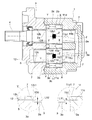
本実施形態に係る歯車ポンプは、主として、歯車収納室11aを内部に有するハウジング構造体1と、このハウジング構造体1の歯車収納室11a内に収納保持され互いに噛み合わせてなる外接歯車対、すなわち駆動歯車2及び従動歯車3と、本実施形態では歯車2、3のフロント側に添接する1つの側板6とを具備する。すなわち本実施形態に係る歯車ポンプは、歯車2、3と、この歯車2、3を収納する歯車収納室11aを内部に有したハウジング構造体1と、その歯車収納室11aに収容された1つの側板6とを具備し、歯車収容室11aの内側で、歯車2、3の一方の側面2a、3aが前記ハウジング構造体1のボディ11と摺接するとともに、他方の側面2a、3aが側板6に摺接する。詳述すれば、ハウジング構造体1と側板6とが、歯車収納室11aの内側で歯車2、3の側面2a、3aにフロント側及びリヤ側からそれぞれ摺接する摺動面11d、6dをそれぞれ有している。
駆動歯車2及び従動歯車3は、複数の歯体を歯底2b、3bから歯先2c、3cすなわち外周面へ向けて所定間隔で放射状に設けた周知のものである。なお、本実施形態では、前記駆動歯車2の中心から駆動軸4を回転軸方向に一体に延伸させて設けているとともに、従動歯車3から従動軸5を回転軸方向に一体に延伸させて設けているが、駆動歯車2と駆動軸4とを別体に構成してもよく、また、従動歯車3と従動軸5とを別体に構成してもよい。
ハウジング構造体1は、例えば、前記歯車収納室11aを有するボディ11と、この歯車収納室11aの開口面を閉塞するカバーたるフロントカバー12とを有している。なお本実施形態ではボディ11単体でリヤ側を閉塞し得るものとしているが勿論当該ボディ11のリヤ側をも開口させ別体のリヤカバーで閉塞させる構成としても良い。
ボディ11は、本実施形態では例えば鋳鉄からなるものを適用している。ボディ11には、前記歯車対すなわち駆動歯車2及び従動歯車3を噛合状態で収容する略眼鏡状の歯車収納室11aと、歯車収納室11aのリヤ側に連通し前記駆動軸4及び従動軸5がそれぞれ挿入可能な軸受孔11b、11cとが形成されている。駆動歯車2を挿入すべき位置寄りの軸受孔11bにはブッシュ7を嵌装し、このブッシュ7に前記駆動軸4の一端部を挿入し回転可能に軸承している。一方、従動歯車3を挿入すべき位置寄りの軸受孔11cにもブッシュ7を嵌装していて、このブッシュ7に前記従動軸5の一端部を挿入し回転可能に軸承している。また、ボディ11には、前記駆動歯車2と従動歯車3との噛合ピッチ円における接線方向側の所定位置、すなわち前記駆動歯車2と従動歯車3との噛合ピッチ円に臨む位置に、図示しない吸込口及び吐出口をそれぞれ開口させてある。
そして本実施形態ではこのボディ11に歯車2、3のリヤ側の側面2a、3aに摺接する摺動面11dを形成している。そして摺動面11dが側面2a、3aに摺接する面積、すなわち摺動面11d側から側面2a、3aを押圧する液圧の作用面積は、軸受孔11b、11cの径の設定により決まる。換言すれば、図1におけるII部を拡大して示すように、軸受孔11b、11cの端部11b1、11c1から歯底2b、3bまでの距離であるシール長さL11によって決まる。すなわち歯車ポンプの作動中は、歯車収容室11a内の高圧の作動液は常に摺動面11dと側面2a、3aとの間の隙間に流れ込もうとすることによって摺動面11dと側面2a、3aとを離間させようとする作用力すなわち側面2a、3aを押圧する作用力が常に働いている。そしてこの作用力の大きさは、摺動面11dと側面2a、3aとが摺接している面積に比例する。そして斯かる面積は本実施形態では、シール長さL11の寸法を厚みとした側面視(図示せず)円環状の領域の大きさに比例することになる。つまり、このシール長さL11が長い程、歯車収容室11a内の作動液によって発生する側面2a、3aをフロント側へ押圧する作用力は大きくなる。
フロントカバー12は、例えばボディ11にボルト等によって着脱可能に装着されて前記歯車収納室11aの前側開口面を閉塞する、例えばアルミダイキャスト製のものであり、前記駆動軸4及び従動軸5がそれぞれ挿入可能な軸受孔12b、12cが形成さている。駆動歯車2を挿入すべき位置寄りの軸受孔12bにはブッシュ7を嵌装し、このブッシュ7に前記駆動軸4の一端部を挿入し回転可能に軸承している。一方、従動歯車3を挿入すべき位置寄りの軸受孔12cにもブッシュ7を嵌装していて、このブッシュ7に前記従動軸5の一端部を挿入し回転可能に軸承している。
側板6は、例えば鉛や、鉛青銅鋳物といった耐食性、強度、耐摩耗性に優れた適宜の素材が用いられている板状のものであり、前記駆動軸4及び従動軸5がそれぞれ挿入可能な軸受孔6b、6cが形成さている。本実施形態では図1に示すように、前記駆動歯車2及び従動歯車3のフロント側の側面2a、3aに添接させるべく配され、駆動歯車2及び従動歯車3の側面2a、3aをシールするためのものである。一方、同図に示すように、前記側板6の非摺動面6eにはガスケット溝6fを設けていて、このガスケット溝6fにガスケット8を嵌め入れるようにしている。
そして本実施形態ではこの側板6に歯車2、3のフロント側の側面2a、3aに摺接する摺動面6dを形成している。そして摺動面6dが側面2a、3aに摺接する面積すなわち摺動面6d側から側面2a、3aを押圧する液圧の作用面積は、図2に示す軸受孔6b、6cの径φSの寸法設定により決まる。換言すれば、図1におけるI部を拡大して示すように軸受孔6b、6cの端部6b1、6c1から歯底2b、3bまでの距離であるシール長さL6によって決まる。すなわち歯車ポンプの作動中は、歯車収容室11a内の高圧の作動液は常に摺動面6dと側面2a、3aとの間の隙間に流れ込もうとすることによって摺動面6dと側面2a、3aとを離間させようとする作用力すなわち側面2a、3aを押圧する作用力が常に働いている。そしてこの作用力の大きさは、摺動面6dと側面2a、3aとが摺接している面積に比例する。そして斯かる面積は本実施形態では、シール長さL6の寸法を厚みとした側面視(図示せず)円環状の領域の大きさに比例することになる。つまり、このシール長さL6が長い程、歯車収容室11a内の作動液によって発生する側面2a、3aをリヤ側へ押圧する作用力は大きくなる。
しかして本実施形態に係る歯車ポンプ又はモータは上述の通り互いに噛み合わせてなる歯車2、3と、この歯車2、3を収納する歯車収納室11aを内部に有しその歯車収容室11aの内側に歯車2、3の両側面2a、3aにそれぞれ摺接するようにした歯車ポンプ又はモータであって、歯車2、3及びボディ11の間の摺動性と、前記歯車2、3及び側板6の間の摺動性とのうち、摺動性の低い方であるボディ11に面した歯車2、3の側面2a、3aに作用する液圧の作用面積を、摺動性の高い方である側板6に面する歯車2、3の側面2a、3aに作用する液圧の作用面積よりも大きくした。詳述すると、歯車2、3の一側面2a、3aに摺接する一方の摺動面11dの摺動性、すなわち鋳鉄の摺動性が他方の摺動面6dの摺動性、すなわち鉛や、鉛青銅鋳物といった素材よりも低いという状況の下で、一方の摺動面11d側から歯車2、3の一側面2a、3aに作用する液圧の作用面積を決定するシール長さL11を他方の摺動面6d側から歯車2、3の側面2a、3aに作用する液圧の作用面積を決定するシール長さL6よりも大きくした。
そうすることにより図1に示すように、ボディ11の摺動面11d側から歯車2、3の側面2a、3aをフロント側へ押圧する作用力である液圧Xが、側板6の摺動面6d側から歯車2、3の側面2a、3aをリヤ側へ押圧する作用力である液圧Yよりも大きくなる。その結果、液圧X及び液圧Yの作用力の差分Zだけ歯車2、3が付勢される。その結果、摺動性の低いボディ11から発生する摩擦が軽減される。
ここで本実施形態では、歯車2、3は両側で同形状或いは対称形状のものを適用している。すなわち歯車については歯底、歯先の寸法を始めとして何ら形状を変えずに上記本実施形態に係る構成を実現している。すなわち図2に示すように本実施形態では、軸受孔6b、6cの径φSよりも、軸受孔11b、11cの径φBを小さくすることのみで、図1にて拡大して示すように、シール長さL11をシール長さL6よりも大きくすることで、液圧が作用する作用面積を大きくしている。
以上のような構成とすることにより、本実施形態では側板6へ向けて付勢する力Zが発生することにより、摺動性が低い一方の摺動面11dにおいて焼き付きが起こり易くなるという不具合を有効に抑制している。加えて、ボディ11の摺動面11dの摺動性が側板6の摺動面6dを低くした場合に起因する機械効率の低下も併せて抑制している。その結果、歯車2、3の両側2a、3aに対しそれぞれ摺動性が異なる素材を使う場合であっても機械効率及び耐久性を有効に担保し得る。そのため、摺動面を構成する設計自由度を有効に向上せしめた歯車ポンプ又はモータを実現している。
特に本実施形態では、リヤ側すなわちボディ11側に側板を設けなくとも従来同様の機械効率並びに耐久性を有しているため、歯車ポンプ又はモータを少なくとも設けずに済んだ側板の厚み寸法だけ歯車の軸方向にコンパクトに構成せしめている。
以下、本発明の各実施形態について説明する。以下の実施形態について、上記実施形態における構成要素に相当するものに対しては同じ符号を付すとともに、その詳細な説明を省略する。
<第二実施形態>
上記第一実施形態では側板6を歯車2、3のフロント側にのみ設けた態様を開示したが勿論、図3及び図4に示す本実施形態のように、歯車2、3のリヤ側にのみ側板6を設けたものとしても良い。
上記第一実施形態では側板6を歯車2、3のフロント側にのみ設けた態様を開示したが勿論、図3及び図4に示す本実施形態のように、歯車2、3のリヤ側にのみ側板6を設けたものとしても良い。
すなわち本実施形態に係る歯車ポンプは、歯車2、3と、この歯車2、3を収納する歯車収納室11aを内部に有したハウジング構造体1と、その歯車収納室11aに収容された1つの側板6とを具備し、歯車収容室11aの内側で、歯車2、3の一方の側面2a、3aがハウジング構造体1のフロントカバー12と摺接するとともに、他方の側面2a、3aが側板6に摺接する。詳述すれば、ハウジング構造体1と側板6とが歯車収納室11aの内側で歯車2、3の側面2a、3aにフロント側及びリヤ側からそれぞれ摺接する摺動面12d、6dを備えたものである。換言すれば本実施形態では、フロントカバー12に歯車2、3のフロント側の側面2a、3aに摺接する摺動面12dを形成している。そして摺動面12dが側面2a、3aに摺接する面積すなわち摺動面12d側から側面2a、3aを押圧する液圧の作用面積は、図4に示す軸受孔12b、12cの径φBの寸法設定により、換言すれば、同図III部を拡大して示すように軸受孔12b、12cの端部12b1、12c1から歯底2b、3bまでの距離であるシール長さL12によって決まる。すなわち歯車ポンプの作動中は、歯車収容室11a内の高圧の作動液は常に摺動面12dと側面2a、3aとの間の隙間に流れ込もうとすることによって摺動面12dと側面2a、3aとを離間させようとする作用力すなわち側面2a、3aを押圧する作用力が常に働いている。そしてこの作用力の大きさは、摺動面12dと側面2a、3aとが摺接している面積に比例する。そして斯かる面積は本実施形態では、シール長さL12の寸法を厚みとした側面視(図示せず)円環状の領域の大きさに比例することになる。つまり、このシール長さL12が長い程、歯車収容室11a内の作動液によって発生する側面2a、3aをリヤ側へ押圧する作用力は大きくなる。
加えて本実施形態では側板6は上記第一実施形態とは対称形状をなすものであって、歯車2、3のリヤ側の側面2a、3aに摺接する摺動面6dを形成している。そして摺動面6dが側面2a、3aに摺接する面積すなわち摺動面6d側から側面2a、3aを押圧する液圧の作用面積は、図4に示す軸受孔6b、6cの径φSの寸法設定により決まる。換言すれば、図3におけるIV部を拡大して示すように軸受孔6b、6cの端部6b1、6c1から歯底2b、3bまでの距離であるシール長さL6によって決まる。すなわち歯車ポンプの作動中は、歯車収容室11a内の高圧の作動液は常に摺動面6dと側面2a、3aとの間の隙間に流れ込もうとすることによって摺動面6dと側面2a、3aとを離間させようとする作用力すなわち側面2a、3aを押圧する作用力が常に働いている。そしてこの作用力の大きさは、摺動面6dと側面2a、3aとが摺接している面積に比例する。そして斯かる面積は本実施形態では、シール長さL6の寸法を厚みとした側面視(図示せず)円環状の領域の大きさに比例することになる。つまり、このシール長さL6が長い程、歯車収容室11a内の作動液によって発生する側面2a、3aをフロント側へ押圧する作用力は大きくなる。
しかして本実施形態に係る歯車ポンプ又はモータは、歯車2、3及びフロントカバー12の間の摺動性と、前記歯車2、3及び側板6の間の摺動性とのうち、摺動性の低い方であるフロントカバー12に面した歯車2、3の側面2a、3aに作用する液圧の作用面積を、摺動性の高い方である側板6に面する歯車2、3の側面2a、3aに作用する液圧の作用面積よりも大きくした。詳述すると、歯車2、3の一側面2a、3aに摺接するフロント側の一方の摺動面12dの摺動性、すなわちアルミダイキャストの摺動性がリヤ側の他方の摺動面6dの摺動性、すなわち鉛や、鉛青銅鋳物といった素材よりも低いという状況の下で、一方の摺動面12d側から歯車2、3の一側面2a、3aに作用する液圧の作用面積を決定するシール長さL12を他方の摺動面6d側から歯車2、3の側面2a、3aに作用する液圧の作用面積を決定するシール長さL6よりも大きくした。
そうすることにより、図3に示すようにフロントカバー12の摺動面12d側から歯車2、3の側面2a、3aをリヤ側へ押圧する作用力である液圧Xが、側板6の摺動面6d側から歯車2、3の側面2a、3aをフロント側へ押圧する作用力である液圧Yよりも大きくなる。これにより、液圧X及び液圧Yの作用力の差分Zだけ歯車2、3が付勢される。その結果、摺動性の低いフロントカバー12から発生する摩擦が軽減される。
本実施形態では、軸受孔6b、6cの径φSよりも、軸受孔12b、12cの径φFを小さくすることのみで、図1にて拡大して示すように、シール長さL12をシール長さL6よりも大きくすることで、液圧が作用する作用面積を大きくしている。
このようなものであっても上記第一実施形態同様、機械効率及び耐久性を有効に担保し、且つコンパクトに構成された歯車ポンプ又はモータを実現している。
<第三実施形態>
上記各実施形態ではフロント側又はリヤ側の何れか一方のみに側板6を設けるとともに他方には設けない構成とすることでコンパクトに構成された歯車ポンプ又はモータを開示したが勿論、フロント側、リヤ側の両方に側板6を設けない態様としても良い。換言すれば、ハウジング構造体1が側板6を有さない構成としても良い。
上記各実施形態ではフロント側又はリヤ側の何れか一方のみに側板6を設けるとともに他方には設けない構成とすることでコンパクトに構成された歯車ポンプ又はモータを開示したが勿論、フロント側、リヤ側の両方に側板6を設けない態様としても良い。換言すれば、ハウジング構造体1が側板6を有さない構成としても良い。
すなわち本実施形態に係る歯車ポンプ又はモータは図5に示すように、歯車2、3と、この歯車2、3を収納する歯車収納室11aを内部に有しその歯車収容室11aの内側に歯車2、3の両側面2a、3aにそれぞれ摺接する摺動面12d、11dを備えたハウジング構造体1とを具備するものである。換言すれば当該歯車ポンプは、ハウジング構造体1を構成するボディ11及びフロントカバー12にそれぞれ摺動面11d、12dを形成したものとしている。そして、図5に拡大して示すように、シール長さL12よりもシール長さL11を大きく設定することにより、作動中、フロントカバー12寄りに歯車2、3を付勢する力Zが発生するようにしている。
具体的に説明すると、本実施形態ではフロントカバー12には上記第二実施形態と同じく歯車2、3のフロント側の側面2a、3aに摺接する摺動面12dを形成している。そして摺動面12dが側面2a、3aに摺接する面積すなわち摺動面12d側から側面2a、3aを押圧する液圧の作用面積は、図4に示す軸受孔12b、12cの径φBの寸法設定により、換言すれば、同図V部拡大図に示すように軸受孔12b、12cの端部12b1、12c1から歯底2b、3bまでの距離であるシール長さL12によって決まる。すなわち歯車ポンプの作動中は、歯車収容室11a内の高圧の作動液は常に摺動面12dと側面2a、3aとの間の隙間に流れ込もうとすることによって摺動面12dと側面2a、3aとを離間させようとする作用力すなわち側面2a、3aを押圧する作用力が常に働いている。そしてこの作用力の大きさは、摺動面12dと側面2a、3aとが摺接している面積に比例する。そして斯かる面積は本実施形態では、シール長さL12の寸法を厚みとした側面視(図示せず)円環状の領域の大きさに比例することになる。つまり、このシール長さL12が長い程、歯車収容室11a内の作動液によって発生する側面2a、3aをリヤ側へ押圧する作用力は大きくなる。
そして本実施形態ではこのボディ11には上記第一実施形態と同じく歯車2、3のリヤ側の側面2a、3aに摺接する摺動面11dを形成している。そして摺動面11dが側面2a、3aに摺接する面積すなわち摺動面11d側から側面2a、3aを押圧する液圧の作用面積は、軸受孔11b、11cの径の設定により、同図VI部に拡大して示すように、軸受孔11b、11cの端部11b1、11c1から歯底2b、3bまでの距離であるシール長さL11によって決まる。すなわち歯車ポンプの作動中は、歯車収容室11a内の高圧の作動液は常に摺動面11dと側面2a、3aとの間の隙間に流れ込もうとすることによって摺動面11dと側面2a、3aとを離間させようとする作用力すなわち側面2a、3aを押圧する作用力が常に働いている。そしてこの作用力の大きさは、摺動面11dと側面2a、3aとが摺接している面積に比例する。そして斯かる面積は本実施形態では、シール長さL11の寸法を厚みとした側面視(図示せず)円環状の領域の大きさに比例することになる。つまり、このシール長さL11が長い程、歯車収容室11a内の作動液によって発生する側面2a、3aをフロント側へ押圧する作用力は大きくなる。
しかして本実施形態に係る歯車ポンプ又はモータは、歯車2、3及びボディ11の間の摺動性と、前記歯車2、3及びフロントカバー12の間の摺動性とのうち、摺動性の低い方であるボディ11に面した歯車2、3の側面2a、3aに作用する液圧の作用面積を、摺動性の高い方であるフロントカバー12に面する歯車2、3の側面2a、3aに作用する液圧の作用面積よりも大きくした。詳述すると、歯車2、3の一側面2a、3aに摺接する一方の摺動面11dの摺動性、すなわち鋳鉄の摺動性が他方の摺動面12dの摺動性、すなわちアルミダイキャストよりも低いという状況の下で、一方の摺動面11d側から歯車2、3の一側面2a、3aに作用する液圧の作用面積を決定するシール長さL11を他方の摺動面12d側から歯車2、3の側面2a、3aに作用する液圧の作用面積を決定するシール長さL12よりも大きくした。
これにより、図5に示すように、ボディ11の摺動面11d側から歯車2、3の側面2a、3aをフロント側へ押圧する作用力である液圧Xが、フロントカバー12の摺動面12d側から歯車2、3の側面2a、3aをリヤ側へ押圧する作用力である液圧Yよりも大きくなる。その結果、液圧X及び液圧Yの作用力の差分Zだけ歯車2、3が付勢される。その結果、摺動性の低いボディ11から発生する摩擦が軽減される。
特に本実施形態では図6に示すように、軸受孔12b、12cの径φFよりも、軸受孔11b、11cの径φBを小さくすることのみで、図5にて拡大して示すように、シール長さL11をシール長さL12よりも大きく設定することで、液圧が作用する作用面積を大きくしている。
以上のように構成することにより本実施形態に係る歯車ポンプ又はモータは上記各実施形態同様に機械効率及び耐久性を有効に担保しつつ、上記各実施形態よりも更にコンパクトなものとなる。
<第四実施形態>
上記各実施形態において示したように本発明によれば、歯車の側面に摺接する素材の選択の幅を広くすることができる。すなわち本実施形態に示すように、歯車のフロント側、リヤ側共に側板6を設けた歯車ポンプ又はモータに対しても本発明を適用することができる。
上記各実施形態において示したように本発明によれば、歯車の側面に摺接する素材の選択の幅を広くすることができる。すなわち本実施形態に示すように、歯車のフロント側、リヤ側共に側板6を設けた歯車ポンプ又はモータに対しても本発明を適用することができる。
すなわち本実施形態に係る歯車ポンプ又はモータは、歯車2、3のフロント側、リヤ側にそれぞれ概ね対称形状をなす、2つの側板6を有している。そしてリヤ側の側板6は上記実施形態同様、鉛や、鉛青銅鋳物といった素材からなる一方、フロント側の側板6は例えば鉄板といった、リヤ側よりも摺動性が低い、換言すれば摩擦係数が高い素材を用いている。そして上記実施形態同様これら対をなす側板6は、歯車2、3のフロント側、リヤ側の側面2a、3aに摺接する摺動面61d、62dをそれぞれ形成している。そして摺動面61d、62dが側面2a、3aに摺接する面積すなわち液圧の作用面積は、図8に示す軸受孔6b、6cの径φS1、φS2の寸法差により決定される。換言すれば、同図VII部拡大図及びVIII部拡大図に示すように軸受孔6b、6cの端部6b1、6c1から歯底2b、3bまでの距離であるシール長さL61、L62によって決まる。すなわち歯車ポンプの作動中は、歯車収容室11a内の高圧の作動液は常に摺動面61dと側面2a、3aとの間の隙間に流れ込もうとすることによって摺動面61dと側面2a、3aとを離間させようとする作用力すなわち側面2a、3aを押圧する作用力が常に働いている。そしてこの作用力の大きさは、摺動面61dと側面2a、3aとが摺接している面積に比例する。そして斯かる面積は本実施形態では、シール長さL61の寸法を厚みとした側面視(図示せず)円環状の領域の大きさに比例することになる。つまり、このシール長さL61が長い程、歯車収容室11a内の作動液によって発生する側面2a、3aをフロント側へ押圧する作用力は大きくなる。他方前記作動液は、常に摺動面62dと側面2a、3aとの間の隙間に流れ込もうとすることによって摺動面62dと側面2a、3aとを離間させようとする作用力すなわち側面2a、3aを押圧する作用力が常に働いている。そしてこの作用力の大きさは、摺動面62dと側面2a、3aとが摺接している面積に比例する。そして斯かる面積は本実施形態では、シール長さL62の寸法を厚みとした側面視(図示せず)円環状の領域の大きさに比例することになる。つまり、このシール長さL62が長い程、歯車収容室11a内の作動液によって発生する側面2a、3aをリヤ側へ押圧する作用力は大きくなる。
しかして本実施形態に係る歯車ポンプ又はモータは、歯車2、3及びフロント側の側板6の間の摺動性と、前記歯車2、3及びリヤ側の側板6の間の摺動性とのうち、摺動性の低い方であるフロント側の側板6に面した歯車2、3の側面2a、3aに作用する液圧の作用面積を、摺動性の高い方であるリヤ側の側板6に面する歯車2、3の側面2a、3aに作用する液圧の作用面積よりも大きくした。詳述すると、歯車2、3の一側面2a、3aに摺接するフロント側の一方の摺動面62dの摺動性、すなわち鉄板の摺動性がリヤ側の他方の摺動面61dの摺動性、すなわち鉛や、鉛青銅鋳物といった素材よりも低いという状況の下で、一方の摺動面62d側から歯車2、3の一側面2a、3aに作用する液圧の作用面積を決定するシール長さL62を他方の摺動面61d側から歯車2、3の側面2a、3aに作用する液圧の作用面積を決定するシール長さL61よりも大きくした。
そうすることにより、図3に示すようにフロント側の側板6の摺動面62d側から歯車2、3の側面2a、3aをリヤ側へ押圧する作用力である液圧Xが、リヤ側の側板6の摺動面61d側から歯車2、3の側面2a、3aをフロント側へ押圧する作用力である液圧Yよりも大きくなる。これにより、液圧X及び液圧Yの作用力の差分Zだけ歯車2、3が付勢される。その結果、摺動性の低いフロント側の側板6から発生する摩擦が軽減される。
本実施形態では、リヤ側の軸受孔6b、6cの径φS1よりも、フロント側の軸受孔6b、6cの径φS2を相対的に小さくすることのみで、図7にて拡大して示すように、シール長さL62をシール長さL61よりも大きくすることで、液圧が作用する作用面積を大きくしている。
このようなものであっても上記各実施形態同様、機械効率及び耐久性を有効に担保した歯車ポンプ又はモータが実現される。
以上、本発明の実施形態について説明したが、各部の具体的な構成は、上述した実施形態のみに限定されるものではなく、本発明の趣旨を逸脱しない範囲で種々変形が可能である。
例えば、上記各実施形態では一の軸に一の歯車のみを備えた態様の歯車ポンプ又はモータを開示したが勿論、一の軸に二つの歯車を備えた、所謂二連式の液圧ポンプ又はモータに本発明を適用しても良い。斯かる二連式の歯車ポンプ又はモータの場合、一方の軸受け側のブッシュを省略し、その省略した寸法だけ軸径を小さくしてシール長さすなわち作用面積を大きくする態様を適用しても良い。
また歯車や側板、さらにはブッシュの具体的な態様は上記実施形態のものに限定されることはなく、既存のものを含め、種々の態様のものを適用することができる。
その他、各部の具体的構成についても上記実施形態に限られるものではなく、本発明の趣旨を逸脱しない範囲で種々変形が可能である。
本発明は産業用機械等に用いられる歯車ポンプ又はモータとして利用することができる。
1…ハウジング構造体
2…歯車(駆動歯車)
3…歯車(従動歯車)
2a、3a…側面
6d、61d、62d、11d、12d…摺動面
L6、L61、L62、L11、L12…作用面積(シール長さ)
2…歯車(駆動歯車)
3…歯車(従動歯車)
2a、3a…側面
6d、61d、62d、11d、12d…摺動面
L6、L61、L62、L11、L12…作用面積(シール長さ)
Claims (3)
- 互いに噛み合わせてなる歯車対と、この歯車対を収納する歯車収納室を内部に有したハウジング構造体と、その歯車収容室に収容された1つの側板とを具備し、前記歯車収容室の内側で、前記歯車対の一方の側面が前記ハウジング構造体と摺接するとともに、前記歯車対の他方の側面が前記側板に摺接する歯車ポンプ又はモータであって、
前記歯車対及び前記ハウジンジング構造体の間の摺動性と、前記歯車対及び前記側板の間の摺動性とのうち、摺動性の低い方の歯車の側面に作用する液圧の作用面積を、摺動性の高い方の歯車の側面に作用する液圧の作用面積よりも大きくしたことを特徴とする歯車ポンプ又はモータ。 - 互いに噛み合わせてなる歯車対と、この歯車対を収納する歯車収納室を内部に有しその歯車収容室の内側で前記歯車対の両側面にそれぞれ摺接するハウジング構造体とを具備する歯車ポンプ又はモータであって、
前記歯車対及び前記ハウジンジング構造体の間の摺動性のうち、摺動性の低い方の歯車の側面に作用する液圧の作用面積を、摺動性の高い方の歯車の側面に作用する液圧の作用面積よりも大きくしたことを特徴とする歯車ポンプ又はモータ。 - 互いに噛み合わせてなる歯車対と、この歯車対を収納する歯車収納室を内部に有したハウジング構造体と、その歯車収容室の内側で前記歯車対の両側面にそれぞれ摺接するように配置された2つの側板とを具備する歯車ポンプ又はモータであって、
前記歯車対及び前記2つの側板の間の摺動性のうち、摺動性の低い方の歯車の側面に作用する液圧の作用面積を、摺動性の高い方の歯車の側面に作用する液圧の作用面積よりも大きくしたことを特徴とする歯車ポンプ又はモータ。
Priority Applications (4)
| Application Number | Priority Date | Filing Date | Title |
|---|---|---|---|
| JP2016523026A JP6226067B2 (ja) | 2014-05-28 | 2014-05-28 | 歯車ポンプ又はモータ |
| PCT/JP2014/064132 WO2015181908A1 (ja) | 2014-05-28 | 2014-05-28 | 歯車ポンプ又はモータ |
| CN201480079130.7A CN106471253B (zh) | 2014-05-28 | 2014-05-28 | 齿轮泵或马达 |
| TW104115869A TWI586892B (zh) | 2014-05-28 | 2015-05-19 | Gear pump or motor |
Applications Claiming Priority (1)
| Application Number | Priority Date | Filing Date | Title |
|---|---|---|---|
| PCT/JP2014/064132 WO2015181908A1 (ja) | 2014-05-28 | 2014-05-28 | 歯車ポンプ又はモータ |
Publications (1)
| Publication Number | Publication Date |
|---|---|
| WO2015181908A1 true WO2015181908A1 (ja) | 2015-12-03 |
Family
ID=54698290
Family Applications (1)
| Application Number | Title | Priority Date | Filing Date |
|---|---|---|---|
| PCT/JP2014/064132 Ceased WO2015181908A1 (ja) | 2014-05-28 | 2014-05-28 | 歯車ポンプ又はモータ |
Country Status (4)
| Country | Link |
|---|---|
| JP (1) | JP6226067B2 (ja) |
| CN (1) | CN106471253B (ja) |
| TW (1) | TWI586892B (ja) |
| WO (1) | WO2015181908A1 (ja) |
Cited By (1)
| Publication number | Priority date | Publication date | Assignee | Title |
|---|---|---|---|---|
| WO2020165963A1 (ja) * | 2019-02-13 | 2020-08-20 | 株式会社島津製作所 | 歯車ポンプまたはモータ |
Families Citing this family (1)
| Publication number | Priority date | Publication date | Assignee | Title |
|---|---|---|---|---|
| KR102231824B1 (ko) * | 2017-10-13 | 2021-03-24 | 가부시키가이샤 시마쓰세사쿠쇼 | 기어 펌프 또는 모터 |
Citations (4)
| Publication number | Priority date | Publication date | Assignee | Title |
|---|---|---|---|---|
| JPS6331273U (ja) * | 1986-08-12 | 1988-02-29 | ||
| JP2012117457A (ja) * | 2010-12-01 | 2012-06-21 | Hitachi Automotive Systems Ltd | 外接歯車ポンプ |
| JP2012202254A (ja) * | 2011-03-24 | 2012-10-22 | Hitachi Automotive Systems Ltd | ポンプ装置 |
| JP2013181446A (ja) * | 2012-03-01 | 2013-09-12 | Sumitomo Precision Prod Co Ltd | 液圧装置 |
Family Cites Families (5)
| Publication number | Priority date | Publication date | Assignee | Title |
|---|---|---|---|---|
| DE10018348A1 (de) * | 2000-04-13 | 2001-10-25 | Bosch Gmbh Robert | Zahnradpumpe, insbesondere für eine Hochdruck-Kraftstoffpumpe |
| CN101379295B (zh) * | 2006-02-20 | 2013-04-10 | 岛津麦库泰姆株式会社 | 齿轮泵 |
| CN201047347Y (zh) * | 2007-06-04 | 2008-04-16 | 胡远祥 | 外啮合齿轮油泵 |
| CN102128165A (zh) * | 2011-03-27 | 2011-07-20 | 长治液压有限公司 | 双进油口液压齿轮泵 |
| WO2013186839A1 (ja) * | 2012-06-11 | 2013-12-19 | 株式会社 島津製作所 | 歯車ポンプ又はモータ |
-
2014
- 2014-05-28 WO PCT/JP2014/064132 patent/WO2015181908A1/ja not_active Ceased
- 2014-05-28 CN CN201480079130.7A patent/CN106471253B/zh active Active
- 2014-05-28 JP JP2016523026A patent/JP6226067B2/ja active Active
-
2015
- 2015-05-19 TW TW104115869A patent/TWI586892B/zh active
Patent Citations (4)
| Publication number | Priority date | Publication date | Assignee | Title |
|---|---|---|---|---|
| JPS6331273U (ja) * | 1986-08-12 | 1988-02-29 | ||
| JP2012117457A (ja) * | 2010-12-01 | 2012-06-21 | Hitachi Automotive Systems Ltd | 外接歯車ポンプ |
| JP2012202254A (ja) * | 2011-03-24 | 2012-10-22 | Hitachi Automotive Systems Ltd | ポンプ装置 |
| JP2013181446A (ja) * | 2012-03-01 | 2013-09-12 | Sumitomo Precision Prod Co Ltd | 液圧装置 |
Cited By (3)
| Publication number | Priority date | Publication date | Assignee | Title |
|---|---|---|---|---|
| WO2020165963A1 (ja) * | 2019-02-13 | 2020-08-20 | 株式会社島津製作所 | 歯車ポンプまたはモータ |
| JPWO2020165963A1 (ja) * | 2019-02-13 | 2021-09-30 | 株式会社島津製作所 | 歯車ポンプまたはモータ |
| JP2023033379A (ja) * | 2019-02-13 | 2023-03-10 | 株式会社島津製作所 | 歯車ポンプまたはモータ |
Also Published As
| Publication number | Publication date |
|---|---|
| TW201544706A (zh) | 2015-12-01 |
| CN106471253A (zh) | 2017-03-01 |
| CN106471253B (zh) | 2018-05-22 |
| JP6226067B2 (ja) | 2017-11-08 |
| TWI586892B (zh) | 2017-06-11 |
| JPWO2015181908A1 (ja) | 2017-04-20 |
Similar Documents
| Publication | Publication Date | Title |
|---|---|---|
| JP2015045326A (ja) | オイルポンプ | |
| JP2010190161A (ja) | 内接ギヤポンプ | |
| JP6226067B2 (ja) | 歯車ポンプ又はモータ | |
| US10267309B2 (en) | Gear pump and gear motor | |
| JP6119748B2 (ja) | 歯車ポンプ又はモータ | |
| WO2014199489A1 (ja) | 歯車ポンプ又はモータ | |
| WO2016181520A1 (ja) | 歯車ポンプ | |
| JP2008157175A (ja) | 回転式ポンプ | |
| JP6079976B2 (ja) | 歯車ポンプ又はモータ | |
| JP2018091386A (ja) | 電動流体圧式リニアアクチュエータ | |
| JP2010038040A (ja) | 歯車ポンプ | |
| JP5009732B2 (ja) | 内接歯車ポンプ | |
| JP5950020B2 (ja) | 歯車ポンプ又はモータ | |
| JP2012077686A (ja) | 歯車ポンプ又はモータ | |
| JP6446961B2 (ja) | 歯車ポンプ又は歯車モータ | |
| JP2013015108A (ja) | 歯車ポンプ又はモータ | |
| JP5314784B2 (ja) | 内接歯車ポンプ | |
| JP2004028005A (ja) | 内接歯車式オイルポンプおよびこれを備えた自動変速機 | |
| JP3213779U (ja) | 内接歯車ポンプ | |
| JPWO2020183546A1 (ja) | はすば歯車ポンプまたはモータ | |
| JP3125540U (ja) | 歯車ポンプ又はモータ | |
| JP7014093B2 (ja) | 歯車ポンプまたはモータ | |
| JPWO2010150388A1 (ja) | ギヤポンプ | |
| JP2005048592A (ja) | 内接歯車ポンプ | |
| WO2020165963A1 (ja) | 歯車ポンプまたはモータ |
Legal Events
| Date | Code | Title | Description |
|---|---|---|---|
| 121 | Ep: the epo has been informed by wipo that ep was designated in this application |
Ref document number: 14893042 Country of ref document: EP Kind code of ref document: A1 |
|
| ENP | Entry into the national phase |
Ref document number: 2016523026 Country of ref document: JP Kind code of ref document: A |
|
| NENP | Non-entry into the national phase |
Ref country code: DE |
|
| 122 | Ep: pct application non-entry in european phase |
Ref document number: 14893042 Country of ref document: EP Kind code of ref document: A1 |