WO2015190053A1 - Lave-linge - Google Patents
Lave-linge Download PDFInfo
- Publication number
- WO2015190053A1 WO2015190053A1 PCT/JP2015/002686 JP2015002686W WO2015190053A1 WO 2015190053 A1 WO2015190053 A1 WO 2015190053A1 JP 2015002686 W JP2015002686 W JP 2015002686W WO 2015190053 A1 WO2015190053 A1 WO 2015190053A1
- Authority
- WO
- WIPO (PCT)
- Prior art keywords
- laundry
- washing
- clutch
- drain valve
- control means
- Prior art date
- Legal status (The legal status is an assumption and is not a legal conclusion. Google has not performed a legal analysis and makes no representation as to the accuracy of the status listed.)
- Ceased
Links
Images





Classifications
-
- D—TEXTILES; PAPER
- D06—TREATMENT OF TEXTILES OR THE LIKE; LAUNDERING; FLEXIBLE MATERIALS NOT OTHERWISE PROVIDED FOR
- D06F—LAUNDERING, DRYING, IRONING, PRESSING OR FOLDING TEXTILE ARTICLES
- D06F33/00—Control of operations performed in washing machines or washer-dryers
- D06F33/30—Control of washing machines characterised by the purpose or target of the control
- D06F33/32—Control of operational steps, e.g. optimisation or improvement of operational steps depending on the condition of the laundry
-
- D—TEXTILES; PAPER
- D06—TREATMENT OF TEXTILES OR THE LIKE; LAUNDERING; FLEXIBLE MATERIALS NOT OTHERWISE PROVIDED FOR
- D06F—LAUNDERING, DRYING, IRONING, PRESSING OR FOLDING TEXTILE ARTICLES
- D06F37/00—Details specific to washing machines covered by groups D06F21/00 - D06F25/00
- D06F37/30—Driving arrangements
- D06F37/40—Driving arrangements for driving the receptacle and an agitator or impeller, e.g. alternatively
-
- D—TEXTILES; PAPER
- D06—TREATMENT OF TEXTILES OR THE LIKE; LAUNDERING; FLEXIBLE MATERIALS NOT OTHERWISE PROVIDED FOR
- D06F—LAUNDERING, DRYING, IRONING, PRESSING OR FOLDING TEXTILE ARTICLES
- D06F2101/00—User input for the control of domestic laundry washing machines, washer-dryers or laundry dryers
- D06F2101/20—Operation modes, e.g. delicate laundry washing programs, service modes or refreshment cycles
-
- D—TEXTILES; PAPER
- D06—TREATMENT OF TEXTILES OR THE LIKE; LAUNDERING; FLEXIBLE MATERIALS NOT OTHERWISE PROVIDED FOR
- D06F—LAUNDERING, DRYING, IRONING, PRESSING OR FOLDING TEXTILE ARTICLES
- D06F2103/00—Parameters monitored or detected for the control of domestic laundry washing machines, washer-dryers or laundry dryers
- D06F2103/02—Characteristics of laundry or load
- D06F2103/04—Quantity, e.g. weight or variation of weight
-
- D—TEXTILES; PAPER
- D06—TREATMENT OF TEXTILES OR THE LIKE; LAUNDERING; FLEXIBLE MATERIALS NOT OTHERWISE PROVIDED FOR
- D06F—LAUNDERING, DRYING, IRONING, PRESSING OR FOLDING TEXTILE ARTICLES
- D06F2103/00—Parameters monitored or detected for the control of domestic laundry washing machines, washer-dryers or laundry dryers
- D06F2103/18—Washing liquid level
-
- D—TEXTILES; PAPER
- D06—TREATMENT OF TEXTILES OR THE LIKE; LAUNDERING; FLEXIBLE MATERIALS NOT OTHERWISE PROVIDED FOR
- D06F—LAUNDERING, DRYING, IRONING, PRESSING OR FOLDING TEXTILE ARTICLES
- D06F2103/00—Parameters monitored or detected for the control of domestic laundry washing machines, washer-dryers or laundry dryers
- D06F2103/24—Spin speed; Drum movements
-
- D—TEXTILES; PAPER
- D06—TREATMENT OF TEXTILES OR THE LIKE; LAUNDERING; FLEXIBLE MATERIALS NOT OTHERWISE PROVIDED FOR
- D06F—LAUNDERING, DRYING, IRONING, PRESSING OR FOLDING TEXTILE ARTICLES
- D06F2103/00—Parameters monitored or detected for the control of domestic laundry washing machines, washer-dryers or laundry dryers
- D06F2103/44—Current or voltage
-
- D—TEXTILES; PAPER
- D06—TREATMENT OF TEXTILES OR THE LIKE; LAUNDERING; FLEXIBLE MATERIALS NOT OTHERWISE PROVIDED FOR
- D06F—LAUNDERING, DRYING, IRONING, PRESSING OR FOLDING TEXTILE ARTICLES
- D06F2105/00—Systems or parameters controlled or affected by the control systems of washing machines, washer-dryers or laundry dryers
- D06F2105/08—Draining of washing liquids
-
- D—TEXTILES; PAPER
- D06—TREATMENT OF TEXTILES OR THE LIKE; LAUNDERING; FLEXIBLE MATERIALS NOT OTHERWISE PROVIDED FOR
- D06F—LAUNDERING, DRYING, IRONING, PRESSING OR FOLDING TEXTILE ARTICLES
- D06F33/00—Control of operations performed in washing machines or washer-dryers
- D06F33/30—Control of washing machines characterised by the purpose or target of the control
- D06F33/32—Control of operational steps, e.g. optimisation or improvement of operational steps depending on the condition of the laundry
- D06F33/42—Control of operational steps, e.g. optimisation or improvement of operational steps depending on the condition of the laundry of draining
Definitions
- This embodiment relates to a washing machine.
- the washing operation is continued in the washing process before the dehydration operation so that unbalanced rotation in the dehydration operation does not occur.
- the agitator is rotated (forward / reverse rotation) during drainage after the washing operation.
- the laundry is evenly arranged at the bottom of the rotating tub at the end of the unwinding operation (at the end of drainage), and unbalanced rotation does not occur in the subsequent dewatering operation.
- the embodiment provides a washing machine that can reliably perform clutch switching after the loosening operation.
- the washing machine is provided with a water tub, a rotating tub provided in the water tub so as to be rotatable around a vertical axis, and a laundry is accommodated therein, and provided at an inner bottom portion of the rotating tub and rotated by a motor.
- An agitator a drain valve for draining from the inside of the rotating tank, a clutch that can be switched to at least a dewatering clutch mode and a washing clutch mode, the clutch as the cleaning clutch mode, and water in the rotating tank.
- a washing operation for rotating the agitator is performed in the accumulated state, and after the washing operation, the clutch is continuously set to the washing clutch mode, and a loosening operation in which the rotation mode of the agitator is different from the washing operation is executed.
- Control means and the control means opens the drain valve during a part of the execution period of the loosening operation and closes the drain valve during another period.
- FIG. 1 shows the overall schematic configuration of the vertical washing machine.
- the outer shell of the washing machine body 1 is composed of an outer box 2 having a rectangular box shape, a base plate 3 provided at the bottom of the outer box 2, and a top cover 4 mounted on the top of the outer box 2.
- a tank 5 is accommodated inside the outer box 2.
- the tank 5 includes a water tank 6 having a bottomed cylindrical shape, and a rotating tank 7 serving as a washing tank and a dewatering tank disposed rotatably in the water tank 6.
- the water tank 6 is supported in a suspended state in a vertical axis state in which the axial direction is the vertical direction by an elastic support mechanism 8 mainly including a suspension bar 8a and a spring 8b.
- a water tank cover 9 is attached to the upper part of the water tank 6, and an inner lid 10 is provided at an almost central portion of the water tank cover 9 so as to be openable and closable.
- the rotary tank 7 has a small hole 7a for dehydration and ventilation on the peripheral side wall, and is rotatable around the vertical axis.
- the laundry is accommodated in the rotating tub 7 so that it can be taken in and out.
- a liquid-filled rotary balancer 11 is attached to the upper end opening of the rotary tank 7.
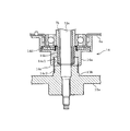
- a stirring body 12 is rotatably disposed at the bottom of the rotary tank 7. As shown in FIGS. 2 and 3, a motor 13 and a clutch 14 are disposed on the outer side (lower side) of the bottom of the water tank 6.
- the motor 13 is composed of an outer rotor type brushless motor, and the rotor 13a is directly connected to the lower end of the stirring shaft 12a.
- the upper end portion of the stirring shaft 12a is connected to the stirring body 12.
- a cylindrical dewatering shaft 7b is rotatably provided around the stirring shaft 12a, and an upper end portion of the dewatering shaft 7b is connected to the rotating tank 7.
- the clutch 14 is provided with a cylindrical body 14a provided so as to be movable up and down around the dewatering shaft 7a.
- a mechanism (not shown) for moving the cylinder 14a up and down and a clutch motor 15 (see FIG. 4) are provided.
- the cylindrical body 14a is movable to a lower position (see FIG. 2) that serves as a dewatering clutch and an upper position (see FIG. 3) that serves as a washing clutch.
- the cylindrical body 14a meshes with the dewatering shaft 7b by the serration mechanism 14b so as to move up and down, and the serration mechanism 14c can move up and down with respect to the boss portion 13b of the outer rotor 13a. Meshed.
- the rotation of the outer rotor 13a is transmitted to the dehydrating shaft 7b in addition to being transmitted to the stirring shaft 12a. That is, the rotation tank 7 and the stirring body 12 are connected to transmit the rotation of the motor 13 to both the rotation tank 7 and the stirring body 12.
- the meshing mechanism 14d for fixing / releasing the cylindrical body 14a with respect to the bearing housing 6a attached to the water tank 6 is separated, so that the rotary tank 7 and the stirring body 12 are integrated. It can be rotated.
- the cylindrical body 14a meshes with the dehydrating shaft 7b by the serration mechanism 14b so as to be vertically movable, and the serration mechanism 14c is separated. Further, the meshing mechanism 14d is meshed, and the cylindrical body 14a is fixed to the bearing housing 6a. As a result, the connection between the rotary tank 7 and the stirring body 12 is released, and the rotation of the motor 13 is transmitted only to the stirring body 12a. In this case, the cylindrical body 14a is fixed to the bearing housing 6a, so that the dehydrating shaft 7b (the rotating tub 7) is fixed to the bearing housing 6a and thus the water tank 6 through the cylindrical body 14a.
- This clutch mode for washing is set at the time of washing operation (detergent washing operation) and rinsing operation (rinse washing operation).
- the cylinder body 14a When switching from the washing clutch mode shown in FIG. 3 to the dewatering clutch mode shown in FIG. 2, the cylinder body 14a is moved downward by the clutch motor 15 to engage the serration mechanism 14c. 12, that is, unless the rotation phases of the upper serration 14 c 1 and the lower serration 14 c 2 of the serration mechanism 14 c match, the dehydrating clutch mode is not achieved.
- the motor 13 As a countermeasure against this, the motor 13 is rotated at a low speed when the cylindrical body 14a is moved downward so that the above-described rotational phase is properly matched (rotating operation for the clutch of the motor 13).
- a drain port 6 b is provided at the bottom of the water tank 6, and this drain port 6 b is connected to a drain pipe 17 via a drain valve 16.
- an air trap 18 for detecting a water level is provided at a portion communicating with the drain port 6b at the bottom of the water tank 6, and one end of an air tube 19 is connected to the air trap 18. The other end of the air tube 19 is connected to a water level sensor 20 described later.
- the top cover 4 is provided above the inner lid 10.
- the top cover 4 has a laundry doorway 21 and has a rectangular frame shape.
- the laundry entrance 21 is opened and closed by a two-fold outer lid 22.
- An operation panel 23 is provided on the front portion (left side in FIG. 1) of the top cover 4.
- the operation panel 23 is provided with an operation input unit 23a (see FIG. 4) composed of various switches and a display unit 23b (see FIG. 4) for performing various displays.
- the control device 25 is arranged.
- the operation input unit 23a includes a time setting switch 23a1 as an operating time change input means and a temporary stop switch 23a2 as a temporary stop input means.
- a component storage portion 26 is provided at the rear portion (right side in FIG. 1) of the top cover 4.
- the above-described water level sensor 20 is disposed in the component storage portion 26, and the rotating tub 7 is provided.
- a water supply device 27 for supplying water therein is disposed.
- the water supply device 27 includes a water supply valve 28 (see FIG. 4), a water supply case 29, a water supply pipe 30, and the like.
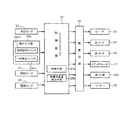
- FIG. 4 shows an outline of the electrical configuration centering on the control device 25.
- the control device 25 is composed mainly of a microcomputer, and has a function as a control means 25a (including the laundry weight detection means 25b) for controlling the overall operation of the washing machine with a software configuration.
- the control means 25a mainly controls, for example, a washing operation, a loosening operation, an intermediate dehydrating operation, a rinsing operation, and a final dehydrating operation.
- the water level detection signal of the water level sensor 20 that detects the water level of water stored in the water tank 6, and the rotation of the motor 13.
- a rotation speed detection signal of the rotation sensor 37 that detects the speed and a current detection signal of the current sensor 38 that detects the current flowing through the motor 13 are input.
- the control device 25 controls the display unit 23b, the motor 13, the drain valve 16, the water supply valve 28, the clutch motor 15, the buzzer 36, and the like via the drive circuit 39 based on these input signals and a control program provided in advance. It is like that.
- the drive circuit 39 is a generic term for drive circuits corresponding to each device.
- control content of the control device 25 (control content of the control means 25a and the like) will be described with reference to FIGS.
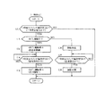
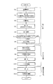
- the control means 25a executes laundry weight detection, water supply, cloth quality detection, water supply, washing operation, loosening operation, drainage, intermediate dehydration operation, water supply, rinse operation (rinse rinse), drainage, and final dewatering operation. Specifically, the following control is performed.
- step S1 From the laundry weight detection (step S1) to the unwinding operation (step S6) is referred to as a washing process, and from the drainage immediately after the unwinding operation (step S7) to the rinsing operation (step S10), it is referred to as a rinsing process.
- step S11 the drainage immediately after the rinsing operation
- step S12 the final dewatering operation
- step S1 the weight of the laundry is detected (laundry weight detection means 25b).
- the laundry 13 is stored in the rotating tub 7, the motor 13 is supplied with a certain amount of electric power to rotate the stirring body 12, and the laundry is stored in the rotating tub 7.
- the laundry weight (weight) is detected from a comparison with the number of rotations obtained by rotating the stirring body 12 by applying a constant electric power to the motor 13 in a state where the laundry is not accommodated.
- This detection data is used for setting the water level.
- the laundry weight may be detected based on the current flowing through the motor 13.
- step S2 water supply is executed.
- the water supply valve 28 is opened in a state where the drain valve 16 is closed, and a predetermined amount of water used for cloth detection is supplied into the rotary tub 7.
- step S3 cloth quality detection is performed (cloth quality detection means).
- This cloth quality detection is performed by applying a constant power to the motor 13 in a state where a certain amount of water is stored in the rotating tub 7 to rotate the stirring body 12, and depending on the rotational speed of the stirring body 12, The cloth quality is detected, for example, one of the three stages of “Wow Wow”, “Standard”, and “Flexible”. This detection data is used for setting the strength of water flow.
- step S4 water supply is executed. This water supply supplies water until the water level (washing water level) set in the rotary tub 7 is reached while the drain valve 16 is kept closed.
- step S5 a washing operation is executed.
- the clutch 14 is in a washing clutch mode.
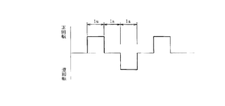
- the motor 13 and the stirring body 12 are intermittently rotated forward and backward intermittently in a state where water is accumulated in the rotating tank 7 and the rotating tank 7 does not rotate.
- the rotation mode (forward / reverse rotation pattern) of the motor 13 is shown in FIG. In this case, the rotation mode repeats the forward rotation for 1 second, the stop for 1 second, the reverse rotation for 1 second, and the pause for 1 second. As a result, a washing water flow is formed in the rotary tank 7.
- washing operation a detergent is supplied in advance in the rotary tank 7, and therefore the washing operation is a so-called detergent washing operation.
- the washing clutch mode is maintained and the process proceeds to step S6 and the loosening operation is executed.
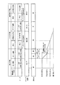
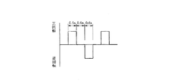
- the motor 13 and thus the stirring member 12 are intermittently rotated forward and backward, and the drain valve 16 is opened and closed. That is, as shown in FIG. 8, the motor 13 repeats a normal rotation for 0.6 seconds, a stop for 0.6 seconds, a reverse rotation for 0.6 seconds, and a pause for 0.6 seconds at the same rotation speed as in the washing operation. Drive in short cycle rotation mode.
- the rotation mode at the time of the loosening operation may be lower than the rotation mode at the time of the washing operation with respect to the rotation mode at the time of the washing operation.
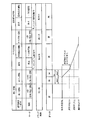
- the water level in the rotary tank 7 is the predetermined water level H0 close
- the water level Hk (see FIG. 9A) at the time of the washing operation is a predetermined level of water level (for example, a predetermined water level H0 of 1/3 or more of the water supply water level Hk at the time of washing operation)
- the drain valve 16 is closed in the period th1).
- the drain valve 16 opens in the period th1 from the start, which is a partial period of the unwinding operation execution period th, and closes in the remaining period th2.
- the laundry is loosened by a weaker water flow (thawing water flow) than the washing operation, and the water level is reduced, so that the laundry is displaced downwardly in the rotating tub 7 and is almost uniformly in the inner bottom portion thereof. Distributed.
- step S7 the drain valve 16 is opened, and the clutch 14 is switched from the washing clutch mode to the dewatering clutch mode.
- the above-described clutch rotation operation of the motor 13 is executed.
- the load on the laundry with respect to the agitator 12 is reduced, and the laundry is also in contact with the agitator 12 and It does not stick to the rotating tank 7.
- the load by the laundry with respect to the motor 13 is small, and the said motor 13 rotates without trouble.
- the clutch 14 becomes an appropriate meshing position (rotation phase), and the clutch 14 is smoothly switched to the dewatering clutch mode.
- step S7 the water in the rotary tub 7 is drained by opening the drain valve 16.
- the laundry since the laundry is distributed in a substantially uniform state on the inner bottom portion of the rotating tub 7 by the above-described loosening operation, the laundry sinks into the bottom surface of the rotating tub 7 as it is and remains in a substantially uniform state.
- step S8 the process proceeds to step S8 to start the intermediate dehydration operation.
- step S8 the dehydration rotation control is performed so as to sequentially increase the rotation speed of the rotary tank 7 as time advances.
- the laundry in the rotating tub 7 remains in a substantially uniform state at the inner bottom of the rotating tub 7, so that the unbalanced rotation does not occur and the dehydration is successful.
- This intermediate dehydration operation is executed for a predetermined time, and the drain valve 16 is closed just before the end.
- step S8 the process proceeds to step S9 to execute water supply.
- This water supply supplies water until the water level set in the rotary tank 7 (water level for rinsing) is reached while the drain valve 16 is kept closed. Then, it transfers to step S10 and performs a rinse operation for predetermined time.
- This rinsing operation is so-called rinsing.
- the stirrer 12 is intermittently rotated forward and backward intermittently in a state where a certain amount of water is accommodated in the rotary tank 7.
- the laundry is rinsed with tap water stored in the rotating tub 7. The above-described loosening operation is not performed after the rinsing operation.
- step S11 the process proceeds to step S11 and drains. This drainage is to drain the water in the rotary tank 7 by opening the drain valve 16.
- step S12 the final dehydration operation is executed for a predetermined time. In this final dehydration operation, the laundry is dehydrated by rotating the rotating tub 7 and the stirring body 12.
- control means 25a also executes the next control at predetermined time intervals while executing the main routine.
- FIG. 10 shows the contents of control related to time setting.
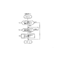
- the control unit 25a determines whether or not the time setting switch 23a1 provided in the operation input unit 23a has been operated. If there is an operation, the control unit 25a determines whether or not the operation is loosening in step T2. Judging. When it is determined that the loosening operation is being performed, the time is not changed (step T3). If “NO” in the step T2, the process shifts to a step T4 to change the time.
- FIG. 11 shows the contents of control related to the suspension.
- the control means 25a determines whether or not there has been an operation (temporary stop command) of the temporary stop switch 23a2 provided in the operation input unit 23a in Step U1, and if “YES”, is the loosening operation being performed in Step U2? Judge whether or not. If the unwinding operation is being performed, the process proceeds to step U3, where the unwinding operation is stopped and the drain valve 16 is uniquely stopped. In step U4, it is determined whether or not the temporary stop switch has been operated again (there is a return command). If it is determined that the return command has been issued, the unwinding operation is stopped, and the control proceeds to the next control (in this case, the draining operation) of the unraveling operation.
- step U2 If “NO” in the step U2, the process shifts to a step U6 to stop the corresponding operation or the corresponding operation. Then, when it is determined in step U7 that the temporary stop switch has been operated again (there is a return command), the process proceeds to step U8 and the operation is resumed.
- FIG. 12 shows the control when the loosening operation is stopped other than the operation of the pause switch (when the abnormal stop function is activated to stop the operation when any abnormality is detected).
- step V1 it is determined whether or not the operation has been stopped during the loosening operation. If “YES”, it is determined in step V2 whether or not the operation has been recovered by, for example, a return process by the user. If driving
- the control means 25a does not open the drain valve 16 in the entire period of the unwinding operation period th, but closes the drain valve 16 in the period th2, which is a partial period of the execution period th. So, at the end of this loosening operation, water will remain in the rotating tub 7 in addition to the moisture contained in the laundry, and as a result, even if there is a large amount of laundry and the overall weight is heavy, The laundry does not stick across the stirring body 12 and the bottom surface of the rotating tub 7. As a result, the stirring body 12 and thus the motor 13 are not locked, and when the clutch 14 is switched to the dewatering clutch mode, the clutch 13 can be rotated without any trouble. As a result, the clutch can be switched reliably after the loosening operation.
- control means 25a closes the drain valve 16 at the predetermined water level H0 among the water levels at which buoyancy acts on the laundry in the rotating tub 7 during the loosening operation, the control means 25a is applied to the stirring body 12.
- the load on the laundry can be reduced, and the laundry can be uniformly distributed. Therefore, it is possible to prevent the occurrence of unbalance rotation in the subsequent dehydration operation (intermediate dehydration operation), and to achieve a successful dehydration.
- control means 25a switches the clutch 14 to the dewatering clutch mode at a predetermined water level H0 at which buoyancy acts on the laundry in the rotating tub 7, so at the time of clutch switching after the loosening operation, The load of the laundry applied to the motor 13 can be further reduced, and the clutch switching can be performed more reliably.
- control means 25a opens the drain valve 16 (period th1) and closes the subsequent drain valve 16 (period th2) in the execution period th of the loosening operation. Unlike the case where the drain valve 16 is opened from the end to the end, the loosening operation is performed while maintaining a certain low water level in the later stage of the loosening operation, and the loosening effect is improved.
- control means 25a can perform the dehydration operation (intermediate dehydration operation) and the rinsing operation in that order, and does not execute the loosening operation after the rinsing operation.
- the rinsing operation When the rinsing operation is performed after the dehydration operation, the rinsing operation may be performed while the laundry is solidified by the dehydration operation, and in this case, when the low water leveling operation is performed after the rinsing operation, the solidification is performed.
- the laundry acts as a large load on the motor 13, and the unraveling effect cannot be expected.
- the unraveling operation that cannot be expected to achieve the unraveling effect is not executed.
- a time setting switch 23a1 is provided as an operation time change input means for inputting a change in the operation time, and the control means 25a changes the operation time from the time setting switch 23a1 during execution of the loosening operation. Even if there was an input, the input was not accepted.
- the unraveling operation is performed at a lower water level than the washing operation, and therefore a cleaning effect cannot be expected.
- the time is set to shorten the unwinding operation, the unwinding effect cannot be expected.
- a temporary stop switch 23a2 is provided as a temporary stop input means for temporarily stopping the operation, and the control means 25a temporarily stops the unwinding operation by the input of the temporary stop switch 23a2 during the unwinding operation.
- the drain valve 16 was closed, and after returning to the temporary stop, the unwinding operation was stopped to shift to the next control of the unraveling operation.
- the drain valve 16 when the loosening operation is temporarily stopped, the drain valve 16 is closed, and after the suspension is resumed, the loosening operation is stopped and the next control of the unraveling operation is performed. Therefore, it is possible to continue washing while preventing resumption of driving that hinders loosening operation by adding laundry.
- control means 25a for example, when an abnormality is detected by an abnormal stop function or the like and the unraveling operation is stopped during the unraveling operation (when other than the temporary stop switch 23a2 is stopped). ), The unwinding operation is canceled after returning from the stop and the control is shifted to the next control of the unraveling operation. Prevent and continue washing.
- FIG. 13 shows a second embodiment.
- the control means 25a starts the loosening operation
- the period th2 ′ is set to a period in which the predetermined water level H0 out of the water levels that can exert buoyancy on the laundry remains in the rotary tub 7 at the end of execution of the loosening operation.
- the clutch 14 is switched to the dewatering clutch mode in the state of the predetermined water level H0.
- the control means 25a does not open the drain valve 16 in the entire period of the unwinding operation execution period th, but opens the drain valve 16 in a period th1 ′ which is a partial period of the execution period th. Since it is closed, at the end of this loosening operation, water will remain in the rotating tub 7 in addition to the water content of the laundry, and as a result, even if there is a large amount of laundry and the overall weight is heavy The laundry does not stick across the stirring body 12 and the bottom surface of the rotating tub 7. As a result, the stirring body 12 and thus the motor 13 are not locked, and when the clutch 14 is switched to the dewatering clutch mode, the clutch 13 can be rotated without any trouble. As a result, the clutch can be switched reliably after the loosening operation.
- FIG. 14 shows the third embodiment, which is different from the first embodiment in that step Sa is added after step S5. That is, the control means 25a executes the loosening operation when the laundry weight detection means 25b detects that the weight of the laundry is equal to or greater than the predetermined weight ("YES" in step Sa), and is less than the predetermined weight. Sometimes the loosening operation is not performed.
- the laundry When the laundry is large (the overall weight is heavy), the laundry is often solidified at the end of the washing operation. Conversely, when the laundry is small, the laundry is rarely solidified. That is, the loosening operation is effective when the laundry weight is heavy, and is wasteful when the amount of laundry is light.
- the loosening operation is performed when the laundry weight detection means 25b detects that the laundry weight is equal to or greater than the predetermined weight, and when the laundry weight is less than the predetermined weight, the loosening operation is performed. Since it is not executed, the loosening operation is not executed wastefully.
- 6 is a water tank
- 7 is a rotating tank
- 12 is an agitator
- 13 is a motor
- 14 is a clutch
- 16 is a drain valve
- 23a1 is a time setting switch (input means for changing operation time)
- 23a2 is a temporary stop switch ( (Pause input means)
- 25a is a control means
- 25b is a laundry weight detection means.
Landscapes
- Engineering & Computer Science (AREA)
- Textile Engineering (AREA)
- Control Of Washing Machine And Dryer (AREA)
- Main Body Construction Of Washing Machines And Laundry Dryers (AREA)
- Detail Structures Of Washing Machines And Dryers (AREA)
Abstract
La présente invention concerne un moyen de commande qui utilise un embrayage dans un mode d'embrayage de lavage continu après une opération de lavage et qui fait tourner un agitateur dans un mode de fonctionnement différent du mode de fonctionnement précité et exécute une opération de démêlage, dans laquelle une soupape de drainage d'eau est ouverte. Le moyen de commande ferme la soupape de drainage d'eau pendant une partie de la période pendant laquelle l'opération de démêlage est exécutée.
Priority Applications (1)
| Application Number | Priority Date | Filing Date | Title |
|---|---|---|---|
| CN201580030016.XA CN106460291B (zh) | 2014-06-11 | 2015-05-27 | 洗衣机 |
Applications Claiming Priority (2)
| Application Number | Priority Date | Filing Date | Title |
|---|---|---|---|
| JP2014120606A JP6366056B2 (ja) | 2014-06-11 | 2014-06-11 | 洗濯機 |
| JP2014-120606 | 2014-06-11 |
Publications (1)
| Publication Number | Publication Date |
|---|---|
| WO2015190053A1 true WO2015190053A1 (fr) | 2015-12-17 |
Family
ID=54833171
Family Applications (1)
| Application Number | Title | Priority Date | Filing Date |
|---|---|---|---|
| PCT/JP2015/002686 Ceased WO2015190053A1 (fr) | 2014-06-11 | 2015-05-27 | Lave-linge |
Country Status (3)
| Country | Link |
|---|---|
| JP (1) | JP6366056B2 (fr) |
| CN (1) | CN106460291B (fr) |
| WO (1) | WO2015190053A1 (fr) |
Cited By (1)
| Publication number | Priority date | Publication date | Assignee | Title |
|---|---|---|---|---|
| EP4596778A4 (fr) * | 2022-11-10 | 2026-03-04 | Lg Electronics Inc | Dispositif de traitement de vêtements et procédé de commande de dispositif de traitement de vêtements |
Families Citing this family (3)
| Publication number | Priority date | Publication date | Assignee | Title |
|---|---|---|---|---|
| CN107675426B (zh) * | 2017-10-31 | 2020-12-08 | 无锡小天鹅电器有限公司 | 洗衣机及其控制方法、控制装置和计算机可读存储介质 |
| CN111519391B (zh) * | 2019-02-01 | 2023-02-10 | 青岛海尔洗衣机有限公司 | 一种洗衣机的控制方法及洗衣机 |
| WO2023008794A1 (fr) * | 2021-07-30 | 2023-02-02 | 삼성전자 주식회사 | Machine à laver |
Citations (6)
| Publication number | Priority date | Publication date | Assignee | Title |
|---|---|---|---|---|
| JPS62163085U (fr) * | 1986-04-03 | 1987-10-16 | ||
| JPH02224791A (ja) * | 1989-02-28 | 1990-09-06 | Toshiba Corp | 脱水兼用洗濯機 |
| JPH03264089A (ja) * | 1990-03-14 | 1991-11-25 | Hitachi Ltd | 洗濯機の運転制御装置 |
| JP2002282575A (ja) * | 2002-02-21 | 2002-10-02 | Sanyo Electric Co Ltd | 洗濯機 |
| JP2007203117A (ja) * | 2002-07-26 | 2007-08-16 | Sharp Corp | 洗濯機 |
| WO2013140857A1 (fr) * | 2012-03-21 | 2013-09-26 | 株式会社 東芝 | Combiné lave-linge/sèche-linge |
Family Cites Families (4)
| Publication number | Priority date | Publication date | Assignee | Title |
|---|---|---|---|---|
| JPH0833788A (ja) * | 1994-07-21 | 1996-02-06 | Hitachi Ltd | 洗濯機の制御方法 |
| JP2004105692A (ja) * | 2002-07-26 | 2004-04-08 | Sharp Corp | 洗濯機 |
| CN2623737Y (zh) * | 2003-05-28 | 2004-07-07 | 王建民 | 工业洗衣机节水控制装置 |
| JP2013244031A (ja) * | 2012-05-23 | 2013-12-09 | Toshiba Corp | 洗濯機 |
-
2014
- 2014-06-11 JP JP2014120606A patent/JP6366056B2/ja active Active
-
2015
- 2015-05-27 WO PCT/JP2015/002686 patent/WO2015190053A1/fr not_active Ceased
- 2015-05-27 CN CN201580030016.XA patent/CN106460291B/zh active Active
Patent Citations (6)
| Publication number | Priority date | Publication date | Assignee | Title |
|---|---|---|---|---|
| JPS62163085U (fr) * | 1986-04-03 | 1987-10-16 | ||
| JPH02224791A (ja) * | 1989-02-28 | 1990-09-06 | Toshiba Corp | 脱水兼用洗濯機 |
| JPH03264089A (ja) * | 1990-03-14 | 1991-11-25 | Hitachi Ltd | 洗濯機の運転制御装置 |
| JP2002282575A (ja) * | 2002-02-21 | 2002-10-02 | Sanyo Electric Co Ltd | 洗濯機 |
| JP2007203117A (ja) * | 2002-07-26 | 2007-08-16 | Sharp Corp | 洗濯機 |
| WO2013140857A1 (fr) * | 2012-03-21 | 2013-09-26 | 株式会社 東芝 | Combiné lave-linge/sèche-linge |
Cited By (1)
| Publication number | Priority date | Publication date | Assignee | Title |
|---|---|---|---|---|
| EP4596778A4 (fr) * | 2022-11-10 | 2026-03-04 | Lg Electronics Inc | Dispositif de traitement de vêtements et procédé de commande de dispositif de traitement de vêtements |
Also Published As
| Publication number | Publication date |
|---|---|
| CN106460291B (zh) | 2019-02-26 |
| CN106460291A (zh) | 2017-02-22 |
| JP2016000084A (ja) | 2016-01-07 |
| JP6366056B2 (ja) | 2018-08-01 |
Similar Documents
| Publication | Publication Date | Title |
|---|---|---|
| JP2005328873A (ja) | ドラム式洗濯機 | |
| US9970142B2 (en) | Washing machine having detergent supply device and method of controlling the same | |
| JP2018000856A (ja) | 洗濯機 | |
| JP6366056B2 (ja) | 洗濯機 | |
| JP2012170684A (ja) | ドラム式洗濯機 | |
| JP2018130376A (ja) | 洗濯機 | |
| KR100653767B1 (ko) | 세탁기의 세탁방법 | |
| JP4844590B2 (ja) | 洗濯機 | |
| JP4591287B2 (ja) | ドラム式洗濯機 | |
| JP2009142612A (ja) | 洗濯機 | |
| JP4929195B2 (ja) | 洗濯機 | |
| JP2013220255A (ja) | 洗濯機 | |
| JP7344633B2 (ja) | 洗濯機 | |
| EP2228483B1 (fr) | Machine à laver de type tambour | |
| JP7204445B2 (ja) | 洗濯機 | |
| JP2010264103A (ja) | 洗濯機 | |
| JP2014018285A (ja) | 洗濯機 | |
| JP2007236441A (ja) | ドラム式洗濯機 | |
| JP2021065583A (ja) | 洗濯機 | |
| JP2015217248A (ja) | 洗濯機 | |
| JP2013034544A (ja) | 洗濯機 | |
| JP2018175039A (ja) | 洗濯機 | |
| KR101079583B1 (ko) | 드럼세탁기 | |
| JP2020014744A (ja) | 洗濯機および洗濯乾燥機 | |
| JP2009268850A (ja) | 洗濯機 |
Legal Events
| Date | Code | Title | Description |
|---|---|---|---|
| 121 | Ep: the epo has been informed by wipo that ep was designated in this application |
Ref document number: 15806526 Country of ref document: EP Kind code of ref document: A1 |
|
| NENP | Non-entry into the national phase |
Ref country code: DE |
|
| 122 | Ep: pct application non-entry in european phase |
Ref document number: 15806526 Country of ref document: EP Kind code of ref document: A1 |