WO2015190238A1 - Dispositif d'affichage pour véhicule - Google Patents
Dispositif d'affichage pour véhicule Download PDFInfo
- Publication number
- WO2015190238A1 WO2015190238A1 PCT/JP2015/064298 JP2015064298W WO2015190238A1 WO 2015190238 A1 WO2015190238 A1 WO 2015190238A1 JP 2015064298 W JP2015064298 W JP 2015064298W WO 2015190238 A1 WO2015190238 A1 WO 2015190238A1
- Authority
- WO
- WIPO (PCT)
- Prior art keywords
- bezel
- image
- vehicle
- instrument panel
- light
- Prior art date
- Legal status (The legal status is an assumption and is not a legal conclusion. Google has not performed a legal analysis and makes no representation as to the accuracy of the status listed.)
- Ceased
Links
Images



























Classifications
-
- G—PHYSICS
- G02—OPTICS
- G02B—OPTICAL ELEMENTS, SYSTEMS OR APPARATUS
- G02B27/00—Optical systems or apparatus not provided for by any of the groups G02B1/00 - G02B26/00, G02B30/00
- G02B27/01—Head-up displays
- G02B27/0101—Head-up displays characterised by optical features
-
- B—PERFORMING OPERATIONS; TRANSPORTING
- B60—VEHICLES IN GENERAL
- B60K—ARRANGEMENT OR MOUNTING OF PROPULSION UNITS OR OF TRANSMISSIONS IN VEHICLES; ARRANGEMENT OR MOUNTING OF PLURAL DIVERSE PRIME-MOVERS IN VEHICLES; AUXILIARY DRIVES FOR VEHICLES; INSTRUMENTATION OR DASHBOARDS FOR VEHICLES; ARRANGEMENTS IN CONNECTION WITH COOLING, AIR INTAKE, GAS EXHAUST OR FUEL SUPPLY OF PROPULSION UNITS IN VEHICLES
- B60K35/00—Instruments specially adapted for vehicles; Arrangement of instruments in or on vehicles
- B60K35/20—Output arrangements, i.e. from vehicle to user, associated with vehicle functions or specially adapted therefor
- B60K35/21—Output arrangements, i.e. from vehicle to user, associated with vehicle functions or specially adapted therefor using visual output, e.g. blinking lights or matrix displays
- B60K35/213—Virtual instruments
-
- B—PERFORMING OPERATIONS; TRANSPORTING
- B60—VEHICLES IN GENERAL
- B60K—ARRANGEMENT OR MOUNTING OF PROPULSION UNITS OR OF TRANSMISSIONS IN VEHICLES; ARRANGEMENT OR MOUNTING OF PLURAL DIVERSE PRIME-MOVERS IN VEHICLES; AUXILIARY DRIVES FOR VEHICLES; INSTRUMENTATION OR DASHBOARDS FOR VEHICLES; ARRANGEMENTS IN CONNECTION WITH COOLING, AIR INTAKE, GAS EXHAUST OR FUEL SUPPLY OF PROPULSION UNITS IN VEHICLES
- B60K35/00—Instruments specially adapted for vehicles; Arrangement of instruments in or on vehicles
- B60K35/20—Output arrangements, i.e. from vehicle to user, associated with vehicle functions or specially adapted therefor
- B60K35/21—Output arrangements, i.e. from vehicle to user, associated with vehicle functions or specially adapted therefor using visual output, e.g. blinking lights or matrix displays
- B60K35/22—Display screens
-
- B—PERFORMING OPERATIONS; TRANSPORTING
- B60—VEHICLES IN GENERAL
- B60K—ARRANGEMENT OR MOUNTING OF PROPULSION UNITS OR OF TRANSMISSIONS IN VEHICLES; ARRANGEMENT OR MOUNTING OF PLURAL DIVERSE PRIME-MOVERS IN VEHICLES; AUXILIARY DRIVES FOR VEHICLES; INSTRUMENTATION OR DASHBOARDS FOR VEHICLES; ARRANGEMENTS IN CONNECTION WITH COOLING, AIR INTAKE, GAS EXHAUST OR FUEL SUPPLY OF PROPULSION UNITS IN VEHICLES
- B60K35/00—Instruments specially adapted for vehicles; Arrangement of instruments in or on vehicles
- B60K35/20—Output arrangements, i.e. from vehicle to user, associated with vehicle functions or specially adapted therefor
- B60K35/21—Output arrangements, i.e. from vehicle to user, associated with vehicle functions or specially adapted therefor using visual output, e.g. blinking lights or matrix displays
- B60K35/23—Head-up displays [HUD]
- B60K35/234—Head-up displays [HUD] controlling the brightness, colour or contrast of virtual images depending on the driving conditions or on the condition of the vehicle or the driver
-
- B—PERFORMING OPERATIONS; TRANSPORTING
- B60—VEHICLES IN GENERAL
- B60K—ARRANGEMENT OR MOUNTING OF PROPULSION UNITS OR OF TRANSMISSIONS IN VEHICLES; ARRANGEMENT OR MOUNTING OF PLURAL DIVERSE PRIME-MOVERS IN VEHICLES; AUXILIARY DRIVES FOR VEHICLES; INSTRUMENTATION OR DASHBOARDS FOR VEHICLES; ARRANGEMENTS IN CONNECTION WITH COOLING, AIR INTAKE, GAS EXHAUST OR FUEL SUPPLY OF PROPULSION UNITS IN VEHICLES
- B60K35/00—Instruments specially adapted for vehicles; Arrangement of instruments in or on vehicles
- B60K35/60—Instruments characterised by their location or relative disposition in or on vehicles
-
- B—PERFORMING OPERATIONS; TRANSPORTING
- B60—VEHICLES IN GENERAL
- B60K—ARRANGEMENT OR MOUNTING OF PROPULSION UNITS OR OF TRANSMISSIONS IN VEHICLES; ARRANGEMENT OR MOUNTING OF PLURAL DIVERSE PRIME-MOVERS IN VEHICLES; AUXILIARY DRIVES FOR VEHICLES; INSTRUMENTATION OR DASHBOARDS FOR VEHICLES; ARRANGEMENTS IN CONNECTION WITH COOLING, AIR INTAKE, GAS EXHAUST OR FUEL SUPPLY OF PROPULSION UNITS IN VEHICLES
- B60K37/00—Dashboards
- B60K37/20—Dashboard panels
-
- B—PERFORMING OPERATIONS; TRANSPORTING
- B60—VEHICLES IN GENERAL
- B60K—ARRANGEMENT OR MOUNTING OF PROPULSION UNITS OR OF TRANSMISSIONS IN VEHICLES; ARRANGEMENT OR MOUNTING OF PLURAL DIVERSE PRIME-MOVERS IN VEHICLES; AUXILIARY DRIVES FOR VEHICLES; INSTRUMENTATION OR DASHBOARDS FOR VEHICLES; ARRANGEMENTS IN CONNECTION WITH COOLING, AIR INTAKE, GAS EXHAUST OR FUEL SUPPLY OF PROPULSION UNITS IN VEHICLES
- B60K2360/00—Indexing scheme associated with groups B60K35/00 or B60K37/00 relating to details of instruments or dashboards
- B60K2360/18—Information management
- B60K2360/184—Displaying the same information on different displays
-
- B—PERFORMING OPERATIONS; TRANSPORTING
- B60—VEHICLES IN GENERAL
- B60K—ARRANGEMENT OR MOUNTING OF PROPULSION UNITS OR OF TRANSMISSIONS IN VEHICLES; ARRANGEMENT OR MOUNTING OF PLURAL DIVERSE PRIME-MOVERS IN VEHICLES; AUXILIARY DRIVES FOR VEHICLES; INSTRUMENTATION OR DASHBOARDS FOR VEHICLES; ARRANGEMENTS IN CONNECTION WITH COOLING, AIR INTAKE, GAS EXHAUST OR FUEL SUPPLY OF PROPULSION UNITS IN VEHICLES
- B60K2360/00—Indexing scheme associated with groups B60K35/00 or B60K37/00 relating to details of instruments or dashboards
- B60K2360/20—Optical features of instruments
- B60K2360/27—Optical features of instruments using semi-transparent optical elements
-
- B—PERFORMING OPERATIONS; TRANSPORTING
- B60—VEHICLES IN GENERAL
- B60K—ARRANGEMENT OR MOUNTING OF PROPULSION UNITS OR OF TRANSMISSIONS IN VEHICLES; ARRANGEMENT OR MOUNTING OF PLURAL DIVERSE PRIME-MOVERS IN VEHICLES; AUXILIARY DRIVES FOR VEHICLES; INSTRUMENTATION OR DASHBOARDS FOR VEHICLES; ARRANGEMENTS IN CONNECTION WITH COOLING, AIR INTAKE, GAS EXHAUST OR FUEL SUPPLY OF PROPULSION UNITS IN VEHICLES
- B60K2360/00—Indexing scheme associated with groups B60K35/00 or B60K37/00 relating to details of instruments or dashboards
- B60K2360/20—Optical features of instruments
- B60K2360/33—Illumination features
- B60K2360/334—Projection means
-
- B—PERFORMING OPERATIONS; TRANSPORTING
- B60—VEHICLES IN GENERAL
- B60K—ARRANGEMENT OR MOUNTING OF PROPULSION UNITS OR OF TRANSMISSIONS IN VEHICLES; ARRANGEMENT OR MOUNTING OF PLURAL DIVERSE PRIME-MOVERS IN VEHICLES; AUXILIARY DRIVES FOR VEHICLES; INSTRUMENTATION OR DASHBOARDS FOR VEHICLES; ARRANGEMENTS IN CONNECTION WITH COOLING, AIR INTAKE, GAS EXHAUST OR FUEL SUPPLY OF PROPULSION UNITS IN VEHICLES
- B60K35/00—Instruments specially adapted for vehicles; Arrangement of instruments in or on vehicles
- B60K35/20—Output arrangements, i.e. from vehicle to user, associated with vehicle functions or specially adapted therefor
- B60K35/29—Instruments characterised by the way in which information is handled, e.g. showing information on plural displays or prioritising information according to driving conditions
-
- G—PHYSICS
- G02—OPTICS
- G02B—OPTICAL ELEMENTS, SYSTEMS OR APPARATUS
- G02B27/00—Optical systems or apparatus not provided for by any of the groups G02B1/00 - G02B26/00, G02B30/00
- G02B27/01—Head-up displays
- G02B27/0101—Head-up displays characterised by optical features
- G02B2027/0118—Head-up displays characterised by optical features comprising devices for improving the contrast of the display / brillance control visibility
Definitions
- the present invention relates to a vehicle display device that is provided on an instrument panel, projects a display image toward a windshield, and allows a passenger to visually recognize a virtual image of the display image reflected on the windshield.
- a display image from a projector provided inside an instrument panel is projected on a windshield, the projected display image is reflected on the windshield, and this reflected image is displayed as a virtual image to a passenger.
- a head-up display (HUD) device for visual recognition has been proposed (see, for example, Patent Document 1).
- a transparent cover that transmits a display image is provided in an opening of an instrument panel, and dust or the like is prevented from entering the inside of the device by the transparent cover.
- the reflected image of the transparent cover and frame reflected on the windshield will be darker than the reflected image of the surrounding instrument panel. It may be visually recognized and give a sense of incongruity to the passenger.
- a reflected image (virtual image) of the display image is formed so that the passenger is focused farther forward than the windshield. Since the reflected image is formed relatively close to the passenger, there is a disadvantage in that parallax occurs between them and the visibility is likely to be lowered.
- An object of the present invention is to provide a vehicular display device that can improve visibility without giving a sense of incongruity to a passenger.
- the display device for a vehicle is provided on the instrument panel, projects a display image toward the windshield, and reflects the display on the windshield.
- a display device for a vehicle that allows a passenger to visually recognize a virtual image of an image, the projection unit being provided on the inner side of the instrument panel and projecting the display image, and the display image projected from the projection unit being the front
- a transmissive portion that transmits toward the glass, and a frame portion that has an opening that allows the display image transmitted through the transmissive portion to pass therethrough and an outer edge portion is continuous with the instrument panel, and is reflected on the windshield.
- the brightness of the reflected image of the instrument panel reflected by the windshield, the reflected image of the transmissive portion, and the reflected image of the frame portion is uniform. , Any one of the reflected images is suppressed from being visually recognized dark, and the uncomfortable feeling given to the passenger is reduced.
- each reflected image of the instrument panel, the transmissive part, and the frame part reflected on the windshield is uniform, each reflected image of the instrument panel, the transmissive part, and the frame part Of these, it is preferable that the brightness ratio of the brightness of the brightest bright reflection image and the brightness of the darkest dark reflection image is 1.3 or less.
- the light-to-dark ratio (brightness of the bright reflection image / brightness of the dark reflection image) is 1.3 or less, the passenger does not feel uncomfortable in visually recognizing the virtual image of the display image. Visibility is obtained, but from the viewpoint of further improving visibility, the light / dark ratio is preferably 1.2 or less. Furthermore, if the light / dark ratio is 1.0, each reflected image has the same brightness, and any reflected image is not lifted up and visually recognized, which is ideal in view of visibility. It is self-evident that it is more preferable to make the contrast ratio closer.
- the vehicle display device is the vehicle display device according to claim 1, wherein the frame portion is inclined downward from an outer edge portion on the instrument panel side toward an edge of the opening portion.
- a frame surface portion is formed, and an angle formed by the frame surface portion and the instrument panel surface is 30 ° or less at the outer edge portion.
- the frame portion has a frame surface portion that is inclined downward toward the inner opening, and an angle formed by the frame surface portion and the instrument panel surface is 30 ° or less at the outer edge portion.
- an angle formed by the frame surface portion and the instrument panel surface is 30 ° or less at the outer edge portion.
- the vehicle display device according to claim 3 is the vehicle display device according to claim 2, wherein the frame surface portion has a gradually decreasing gradient from the outer edge portion toward the edge of the opening portion. It is characterized by being formed into a large upward convex curved surface.
- the frame surface portion is formed in an upwardly convex curved shape, and the gradient on the outer edge portion side is gently formed, so that the opening can be made while smoothly continuing to the instrument panel at the boundary portion.
- the depth on the part side can be ensured, and the degree of freedom in setting the installation height of the transmission part can be increased.
- the frame surface portion is formed in a curved shape, the brightness change in the reflected image of the frame portion reflected on the windshield can be moderated, and the uncomfortable feeling given to the passenger can be further reduced.
- the vehicle display device is the vehicle display device according to any one of claims 1 to 3, wherein the frame portion is formed using a translucent material that transmits light.
- An irradiating means for irradiating light is provided on the back side of the frame portion.
- the irradiating means is provided on the back side of the frame portion formed using the semi-transmissive material, and the light irradiated from the irradiating means is transmitted to the surface side of the frame portion.
- the surface can be brightened, and it is possible to suppress the reflection image reflected by the frame portion on the windshield from becoming darker than the reflection image of the instrument panel, and to bring the contrast ratio close to 1.0.
- the transmittance of the frame portion formed using the semi-transmissive material is preferably about 20%, and the frame portion having such a transmittance allows the boarding while transmitting the light from the irradiation means. It is possible to prevent the inner side of the frame portion from being seen through from the person.
- the vehicle display device is the vehicle display device according to any one of claims 1 to 4, wherein at least one of the frame portion and the instrument panel has a mutual surface. A surface treatment for equalizing the glossiness is provided.
- the frame portion and the instrument panel are provided with a surface treatment, and the glossiness of each surface is made equal, so that external light or the like is reflected on these frame portions and the instrument panel.
- the appearance of the reflected image reflected on the windshield can be made closer, making it difficult for passengers to feel uncomfortable.
- the surface treatment provided on the frame is the same skin texture.
- the surface of the instrument panel that tends to produce a relatively bright reflected image is provided with fine irregularities that are finer than the irregularities of the skin wrinkles, and the gloss is reduced by diffusing the light due to the fine irregularities. May be a means for equalizing.
- one of the reflected image of the instrument panel reflected by the windshield, the reflected image of the transmissive portion, and the reflected image of the frame portion is visually recognized as dark. Therefore, it is possible to improve the visibility of the reflected image (virtual image) of the display image by reducing the parallax caused by the dark reflected image without causing the passenger to feel uncomfortable.
- FIGS. 1 to 6 are views referring to the first invention
- FIGS. 7 to 22 are views referring to the second invention
- FIGS. 23 to 33 are views referring to the third invention.
- 34 to 41 refer to the fourth invention
- FIGS. 42 to 47 refer to the fifth invention
- FIGS. 48 to 58 refer to the sixth invention.
- FIGS. 59 to 73 are diagrams for referring to the seventh invention
- FIGS. 74 to 79 are diagrams to refer to the eighth invention.
- FIG. 8 is a view showing a cross section taken along line A2001-A2001 of the vehicle display device shown in FIG.
- FIG. 7 is a cross-sectional view showing a state in which the vehicle display device is assembled to the vehicle.
- FIG. It is a figure which shows the modification of the display apparatus for vehicles shown by FIG.
- FIG. 8 It is a figure which shows the state by which light was projected on the windshield using the display apparatus for vehicles shown by FIG. 8
- FIG. It is a figure which shows the state by which light was projected on the windshield using the display apparatus for vehicles shown by FIG. 9, FIG.
- It is a figure which shows the modification of the bezel body shown by FIG. It is a figure which shows the other modification of the bezel body shown by FIG.
- FIG. It is a figure which shows the further another modification of the bezel body shown by FIG.
- FIG. It is a figure which shows the state as which light was projected on the windshield using the display apparatus for vehicles provided with the bezel body shown by FIG. It is a figure which shows the state as which light was projected on the windshield using the display apparatus for vehicles provided with the bezel body shown by FIG. It is a top view which shows the bezel body in the display apparatus for vehicles concerning 3rd embodiment of this invention. It is a figure which shows the state as which light was projected on the windshield using the display apparatus for vehicles provided with the bezel body shown by FIG. It is a figure which shows the modification of the bezel body shown by FIG. It is a figure which shows the state as which light was projected on the windshield using the display apparatus for vehicles provided with the bezel body shown by FIG. It is a figure which shows the conventional display apparatus for vehicles.
- FIG. 23 It is a perspective view which shows a mode that the display apparatus for vehicles concerning 1st Embodiment of this invention was assembled
- FIG. 35 is a cross-sectional view showing a state where the vehicle display device shown in FIG. 34 is attached to the vehicle.
- FIG. 35 is a perspective view showing an instrument panel to which the vehicle display device shown in FIG. 34 is attached.
- FIG. 35 is a perspective view schematically showing a lower surface of the mounting portion in the vehicle display device shown in FIG. 34. It is a perspective view which expands and shows the leg part in the display apparatus for vehicles shown by FIG. It is sectional drawing which shows the conventional display apparatus for vehicles typically. It is sectional drawing which shows the other conventional display apparatus for vehicles typically. It is a disassembled perspective view which shows the display apparatus for vehicles concerning one Embodiment of this invention.
- FIG. 43 is a perspective view showing a state in which the bezel body shown in FIG. 42 is assembled.
- FIG. 43 is a cross-sectional view schematically showing a state in which the vehicle display device shown in FIG. 42 is mounted on a vehicle.
- FIG. It is a figure which shows the state as which light was projected on the windshield using the display apparatus for vehicles shown by FIG. It is sectional drawing which shows the conventional display apparatus for vehicles typically. It is sectional drawing which shows the other conventional display apparatus for vehicles typically. It is a perspective view which shows a mode that the display apparatus for vehicles concerning 1st Embodiment of this invention was assembled
- FIG. 1 It is a schematic diagram which shows the projection image projected on a windshield by the display apparatus for vehicles of FIG. It is a schematic diagram which shows the instrument panel concerning 2nd Embodiment of this invention. It is a schematic diagram which shows the projection image projected on a windshield from opening of the instrument panel of FIG. It is sectional drawing which shows the conventional display apparatus for vehicles typically. It is sectional drawing which shows the other conventional display apparatus for vehicles typically. It is a schematic diagram which shows the projection image projected on a windshield by the vehicle display apparatus of FIG. It is a perspective view which shows a mode that the display apparatus for vehicles concerning 1st Embodiment of this invention was assembled
- FIG. 60 is a cross-sectional view of the vehicle display device of FIG. 59.
- FIG. 60 is an exploded perspective view of the vehicle display device of FIG. 59.
- FIG. 60 is a diagram illustrating assembly of the instrument panel of the vehicle display device of FIG. 59 to the wall facing the windshield.
- FIG. 60 is a diagram showing an image projected on the windshield by the vehicle display device of FIG. 59. It is a figure which shows the extraction opening of the pre-assembly protection sheet in the display apparatus for vehicles of FIG.
- FIG. 60 is a diagram showing a holding structure for a pre-assembly protective sheet in the vehicle display device of FIG. 59.
- FIG. 60 is a diagram illustrating an example of a dustproof member that closes a drawing port of a pre-assembly protective sheet in the vehicle display device of FIG. 59.
- FIG. 60 is a diagram showing another example of the dustproof member that closes the drawing port of the pre-assembly protective sheet in the vehicle display device of FIG. 59.
- FIG. 60 is a diagram showing still another example of the dustproof member that closes the drawing port of the pre-assembly protective sheet in the vehicle display device of FIG. 59.
- It is a figure which shows the instrument panel concerning 2nd Embodiment of this invention.
- It is a figure which shows the projection image projected on a windshield from opening of the instrument panel of FIG.
- It is sectional drawing which shows the conventional display apparatus for vehicles typically.
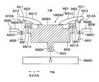
- FIG. 75 is a cross sectional view taken along a line II8000-II8000 in FIG. 74.
- FIG. 75 is a cross-sectional view showing a state in which the vehicle display device of FIG. 74 is attached to an instrument panel.
- FIG. 75 is a cross-sectional view showing a state in which the image projector of the vehicle display device of FIG. 74 is taken out from the instrument panel.
- It is sectional drawing which shows the vehicle drift display apparatus of a modification.
- the vehicle display device 1 of the present embodiment is provided on the instrument panel I of the vehicle, projects a display image G1 toward the windshield F, and reflects it on the windshield F.
- a passenger is allowed to visually recognize a virtual image G3 of the image G2. That is, as shown in FIGS. 2 and 3, the display image G1 projected from the vehicular display device 1 is reflected by the windshield F and reaches the passenger's eye range ER.
- the reflected display image G2 is visually recognized as a virtual image G3 ahead of the windshield F.
- the passenger can obtain a forward view through the windshield F and can visually recognize the virtual image G3 in the forward view.
- the vehicle display device 1 includes a device main body 2 provided on the inner side of the instrument panel I, a display unit 3 as a projection unit provided inside the device main body 2 for projecting a display image, A bezel body as a frame having a transparent cover 4 as a transmission part that transmits the display image projected from the display unit 3 toward the windshield F, and an opening 51 through which the display image transmitted through the transparent cover 4 passes. 5 and a light guide member 6 as an irradiating means provided on the vehicle front side on the lower side (back side) of the bezel body 5.
- the diagonally upper left side in FIG. 1 and the left side in FIG. 2 are the front side of the vehicle, and are hereinafter simply referred to as the vehicle front side.
- the apparatus main body 2 includes a box-shaped casing 21, an optical unit 22 that is provided inside the casing 21 and guides a display image from the display unit 3 to the transparent cover 4, and a control unit (not shown). It is configured.
- the casing 21 is formed to open upward, and the transparent cover 4 is attached to the opening.
- a support member 24 is fixed to the front side of the housing 21 via a bracket 23, and the light guide member 6 is supported by the support member 24.
- a casing 21 is fixed to a vehicle main body such as a vehicle body panel in the vehicle, and is not fixed directly to the instrument panel I but has an edge.
- the optical unit 22 is configured to include a plurality of mirrors that reflect the display image projected from the display unit 3 and a plurality of lenses that are enlarged and reduced, and a virtual image G3 that is visually recognized by the passenger is focused far away on the vehicle front side. So that the projection path of the display image G1 from the display unit 3 is extended.
- the display unit 3 has a display that receives a signal from the control unit and generates a display image.
- the display unit 3 includes a transmissive liquid crystal display panel, for example, and can display numerical values, characters, figures, and the like. Information (display image) can be displayed as necessary.
- the display unit 3 is provided with a light source for illumination such as a backlight, and projects visible information displayed by the display device as a light beam.
- the transparent cover 4 is a rectangular surface material that has translucency and has a curved surface that protrudes downward, and is supported by the housing 21 in a forward-downward direction toward the front side of the vehicle.
- the bezel body 5 has an opening 51 at the center thereof, and an outer edge 52 is provided continuously to the instrument panel I and is supported by the instrument panel I.
- the opening 51 has a rectangular edge 51 ⁇ / b> A along the edge of the transparent cover 4, and allows the display image G ⁇ b> 1 transmitted through the transparent cover 4 to pass therethrough.
- the outer edge portion 52 is continuous with a step at the same height as the surface Ia of the instrument panel I, and is attached so that no gap is generated between the outer edge portion 52 and the instrument panel I.
- the bezel body 5 has a frame surface portion 53 that is inclined downward from the outer edge portion 52 toward the edge 51 ⁇ / b> A of the opening 51, and the frame surface portion 53 has an outer edge.
- the bezel body 5 is formed in an upwardly convex curved surface shape in which the gradient gradually decreases from the portion 52 toward the edge 51A of the opening 51. That is, the entire surface of the bezel body 5 is directed toward the opening 51 at the center. It is formed in a mortar shape.
- the bezel body 5 has a front frame portion 5A located on the front side of the vehicle, a pair of horizontal frame portions 5B located on the left and right sides, and a rear frame portion 5C located on the rear side of the vehicle. It is formed in a rectangular ring shape.
- Such a bezel body 5 is made of a thermoplastic resin having an appropriate thickness, and is formed by, for example, injection molding.
- This thermoplastic resin is a translucent material that transmits light, and preferably has a transmittance of about 20% after molding.
- the frame surface portion 53 of the bezel body 5 is provided with the same surface treatment as the surface Ia of the instrument panel I.
- the surface treatment includes an uneven finishing process for forming unevenness at the time of injection molding, and a coating process for coating the surface after molding, and includes a frame surface portion 53 after the surface treatment, and a surface Ia of the instrument panel I. Are set to have the same glossiness and color.
- the glossiness based on the value measured using a glossmeter or the like, if the glossiness value of the frame surface portion 53 is ⁇ 10% of the glossiness value of the surface Ia of the instrument panel I, the glossiness It can be regarded as equivalent.
- examples of the irregularity finishing process at the time of injection molding include a textured process for forming irregularities having an irregular dimension of about 0.1 mm to 1 mm.
- a so-called heat & cool injection molding is an example of a molding method for performing such skin-texturing.
- heat and cool injection molding use a mold that has unevenness on the molding surface on the molding surface, inject the molten resin into the cavity with this mold heated, cool the mold, and then open the mold
- the textured surface irregularities can be provided on the frame surface portion 53 of the bezel body 5.
- the surface Ia of the instrument panel I is viewed brightly, the surface Ia has an uneven size smaller than the skin wrinkle (for example, A fine unevenness process for forming fine unevenness of 10 ⁇ m to 100 ⁇ m) may be performed to reduce the glossiness of the surface Ia.
- the front frame portion 5A of the bezel body 5 is provided with the back side open toward the vehicle front side, and the light guide member 6 is provided below the front frame portion 5A.
- the light guide member 6 is a prism that reflects external light incident from the front glass F on the front side of the vehicle and irradiates the light toward the back surface of the front frame portion 5A. It is formed with an appropriate polygonal cross section having a plurality of reflecting surfaces.
- the support member 24 that supports the light guide member 6 is made of a metal plate or the like, the surface on the light guide member 6 side is a mirror surface, and reflects light emitted from the light guide member 6 toward the light guide member 6. It is configured. As described above, the light guide member 6 and the support member 24 are provided below the front frame portion 5 ⁇ / b> A of the bezel body 5, so that external light incident from the windshield F is reflected and diffused inside the light guide member 6. At the same time, a part of the light is reflected by the support member 24 and irradiated from the upper surface of the light guide member 6 toward the back surface of the front frame portion 5A as dispersed light. The irradiated dispersed light passes through the front frame portion 5A of the semi-transparent bezel body 5 and is emitted above the front frame portion 5A so that the frame surface portion 53 of the front frame portion 5A looks bright. become.
- the lateral frame portion 5 ⁇ / b> B of the bezel body 5 is provided with the outer edge portion 52 in contact with the left and right instrument panels I.
- the frame surface portion 53 of the lateral frame portion 5 ⁇ / b> B and The surfaces of the instrument panel I are continuously provided without any step so that the angle ⁇ formed with the surface Ia of the instrument panel I is 30 ° or less. Since the bezel body 5 is formed so that the angle ⁇ between the frame surface portion 53 and the surface Ia of the instrument panel I is thus reduced, as a reflected image reflected on the windshield F shown in FIG.
- the contrast at the boundary between the reflected image Ir of the instrument panel I and the reflected image 5r of the bezel body 5 can be suppressed so as not to stand out.
- the angle ⁇ between the frame surface portion 53 and the surface Ia of the instrument panel I at the outer edge portion 52 may be 30 ° or less, but from the viewpoint of reducing contrast, the angle ⁇ is 20 ° or less. Is preferred.
- the transparent cover 4 is provided so as to be inclined downward toward the front side of the vehicle, and the front frame portion 5A of the bezel body 5 is directed toward the front side of the vehicle from the front end edge thereof. It stands up in an upward convex curved surface. Due to the arrangement of the transparent cover 4 and the front frame portion 5A of the bezel body 5, when the incident angle of external light (sunlight) is low, the external light reaches the transparent cover 4 by being blocked by the front frame portion 5A. It is supposed not to. On the other hand, when the incident angle (solar altitude) of outside light increases, the incident angle with respect to the transparent cover 4 that falls forward is increased although it reaches the transparent cover 4. Even if this outside light is reflected by the windshield F, it does not go to the eye range ER side, so that the passenger's illusion can be prevented.
- the front frame portion 5A is reflected in front of the reflected image 4r of the transparent cover 4 as shown in FIG. It is supposed to be depressed.
- the frame surface portion 53 is illuminated and brightened by external light, and the dispersed light from the light guide member 6 on the back side is transmitted and the frame surface portion 53 is formed as described above.
- the brightness of the reflection image 4r of the transparent cover 4 on which the frame surface portion 53 is reflected increases as the frame becomes brighter.
- the brightness of the reflection image 4r of the transparent cover 4 and the reflection image Ir of the instrument panel I and the reflection image 5r of the bezel body 5 are increased. Difference (contrast) is reduced, and the reflected image 4r of the transparent cover 4 can be suppressed from being conspicuous when viewed dark.
- the reflected image Ir of the instrument panel I, the reflected image 5r of the bezel body 5, and the transparent cover are reflected as the reflected image reflected on the windshield F shown in FIG.
- the four reflected images 4r have the same brightness.
- each reflected image Ir, 5r, 4r you may measure using measuring instruments, such as an illuminometer, and the image obtained by imaging with imaging devices, such as a CCD camera, is obtained.
- the brightness of each part may be calculated by image processing, or the brightness may be calculated in comparison with a brightness sample, and any measurement method can be employed.
- the light / dark ratio Rr is more preferably 1.2 or less.
- Such a light / dark ratio Rr equalizes the glossiness with the surface Ia of the instrument panel I by the surface treatment of the frame surface portion 53 of the bezel body 5,
- the transmittance is adjusted by changing the resin material and the thickness of the bezel body 5, the intensity and direction of the irradiation light from the light guide member 6 with respect to the back surface of the front frame portion 5A, the curved shape of the front frame portion 5A Or the angle of the transparent cover 4 is changed to adjust the brightness of the reflected image 4r of the transparent cover 4 or the like, and is set by a combination of the shape, size, and material of each part.
- the shape of the instrument panel I and the angle and curvature of the windshield F vary depending on the vehicle model, and even in the same vehicle model, the finish (unevenness and color) of the surface Ia of the instrument panel I may be different. Accordingly, the shape, dimensions, material, surface treatment, and the like of the bezel body 5 and the transparent cover 4 are set according to the individual instrument panel I and the windshield F.
- the reflected image reflected on the windshield F the reflected image Ir of the instrument panel I, the reflected image 5r of the bezel body 5, and the reflected image 4r of the transparent cover 4 have the same brightness.
- the contrast between the respective reflected images Ir, 5r, 4r is suppressed, and any of the reflected images Ir, 5r, 4r is not conspicuous, and the uncomfortable feeling given to the passenger can be reduced. Therefore, the visibility of the virtual image G3 of the display image G2 can be improved by reducing the parallax caused by the dark reflected images Ir, 5r, 4r.
- the angle ⁇ formed by the frame surface portion 53 of the bezel body 5 and the surface Ia of the instrument panel I is 30 ° or less at the boundary portion between them, the contrast of the reflected images Ir and 5r reflected on the windshield F is suppressed. be able to. Further, since the frame surface portion 53 is formed in an upwardly convex curved shape and the gradient on the outer edge portion 52 side is gently formed, the outer edge portion 52 and the instrument panel I are smoothly continuous. The brightness change of the reflected image 5r of the bezel body 5 reflected on the glass F can be moderated, and the uncomfortable feeling given to the passenger can be further reduced.
- the difference can be made inconspicuous, and the uncomfortable feeling given to the passenger can be reduced. it can.
- the opening 51 side in the bezel body 5 can be deepened, and the installation height and angle of the transparent cover 4 can be increased.
- the bezel body 5 is formed using a semi-transmissive material, and a light guide member 6 is provided below the front frame portion 5A of the bezel body 5 so that light irradiated from the light guide member 6 Since the surface of the front frame portion 5A is brightened by being transmitted to the surface side of the frame portion 5A, it is possible to suppress the reflection image of the front frame portion 5A reflected on the windshield F from becoming dark. Further, since the bright front frame portion 5A is reflected at the tip of the reflection image 4r of the transparent cover 4, the brightness of the reflection image 4r of the transparent cover 4 is increased, and the reflection image Ir of the instrument panel I and the reflection of the bezel body 5 are increased. The contrast with the image 5r is reduced, and the reflected image 4r of the transparent cover 4 can be suppressed from being visually recognized as dark.
- the frame surface portion 53 of the bezel body 5 is subjected to a surface treatment such as skinning or coloring, and the glossiness and color of the frame surface portion 53 and the surface Ia of the instrument panel I are set to be equal.
- a surface treatment such as skinning or coloring
- the glossiness and color of the frame surface portion 53 and the surface Ia of the instrument panel I are set to be equal.
- the reflected image Ir of the instrument panel I and Contrast with the reflected image 5r of the bezel body 5 can be further suppressed.
- the present invention is not limited to the above-described embodiment, and includes other configurations and the like that can achieve the object of the present invention, and the following modifications and the like are also included in the present invention.
- the bezel body 5 formed separately from the instrument panel I is used as the frame having the opening.
- the present invention is not limited to this, and the frame is integrated as a part of the instrument panel. It may be formed.
- the frame portion is not limited to a mortar shape having a downward slope toward the opening 51 like the bezel body 5 of the above embodiment, and is formed substantially flat with the surface of the instrument panel. It may also be one that is formed with an upward slope toward the opening instead of a downward slope.
- transmission part was provided in the front downward toward the vehicle front side, not only this but the permeation
- the bezel body 5 as a frame part is formed from a translucent material, and is comprised with a light transmittance, and the light guide member 6 as an irradiation means under the front frame part 5A.
- the frame portion does not have to be light transmissive, and in this case, the irradiation means can be omitted.
- the irradiation means is not limited to the one provided below the front frame portion 5A, and may be provided below the entire bezel body 5 including the horizontal frame portion 5B and the rear frame portion 5C. What is necessary is just to be provided in at least any one of 5 A of frame parts, the horizontal frame part 5B, and the rear frame part 5C.
- the irradiating means is not limited to the light guide member 6 that irradiates and transmits external light by being incident, transmitted, and reflected, and may include a light emitting device that emits light by electric power, a sensor that detects external light, and the like.
- a second invention is a bezel body and a vehicle display device having the following characteristics.
- An image projector that is fitted into a wall of a vehicle instrument panel facing the windshield and disposed in the instrument panel forms part or all of the periphery of an opening for projecting an image on the windshield.
- a bezel body having a bezel member, A light source unit that is provided inside the bezel member and that emits light toward the bezel member; The bezel body, wherein at least a part of the bezel member is configured to transmit light from the light source unit so that light emitted from the light source unit is projected onto the windshield.
- the entire bezel member is configured to transmit light from the light source unit, and the bezel member is formed in an annular shape in plan view so as to form the entire periphery of the opening ( The bezel body as described in 1).
- the light source unit is provided to irradiate light to the entire bezel member;
- the bezel body according to (2), wherein the bezel member is formed so that the thickness gradually changes from the outer edge to the inner edge of the bezel member.
- the present invention relates to a bezel body disposed on an instrument panel of a vehicle and a vehicle display device including the bezel body.
- a vehicle display device as a head-up display device that projects an image onto a windshield of a vehicle is provided in an instrument panel (see, for example, Patent Document 21).
- the vehicle display device 2700 described in Patent Document 21 is mounted in an instrument panel I2000 having an opening H2000 provided in a wall A2000 facing the windshield F2000, and the image projector 2701 is provided.
- an image is projected onto the windshield F2000 through the opening H2000.
- Patent Document 21 Japanese Patent Application Laid-Open No. 2007-148092 [Summary of Invention] [Problems to be solved by the invention]
- the image projector 2701 includes a display source 2711, a reflection unit 2712 for reflecting an image from the display source, and a housing 2713 in which the display source 2711 and the reflection unit 2712 are accommodated.
- An opening 2713 a is formed on the top surface of the housing 2713.
- the image projector 2701 reflects the image projected by the display source 2711 by the reflection unit 2712 and projects it on the windshield F2000 through the opening 2713a. Thereby, the passenger of a vehicle recognizes as an image displayed on windshield F2000.
- EP2000 shown in FIG. 22 shows the eyepoint of this passenger.
- the invention described in (1) is directed to an image projector that is fitted in a wall facing a windshield in an instrument panel of a vehicle and disposed in the instrument panel.
- a bezel body having a bezel member that forms part or all of a peripheral edge of an opening for projecting an image on a light source, and a light source unit that is provided inside the bezel member and that emits light toward the bezel member.
- the bezel member is configured so that at least a part thereof transmits light from the light source unit so that light emitted from the light source unit is projected onto the windshield. Is the body.
- the invention described in (2) is the invention described in (1), wherein the whole of the bezel member is configured to transmit light from the light source unit, and the bezel member is arranged at the periphery of the opening. It is characterized by being formed in an annular shape in plan view so as to form the whole.
- the invention described in (3) is characterized in that, in the invention described in (2), the light source part is arranged to face at least one of an outer edge part and an inner edge part of the bezel member. Is.
- the invention described in (4) is the invention described in (2), wherein the light source unit is provided so as to irradiate light to the entire bezel member, and the bezel member is an outer edge portion of the bezel member. It is formed so that thickness may change gradually as it goes to an inner edge part.
- a portion of the bezel body that transmits light emitted from the light source unit indicates a shape of a symbol indicating predetermined information on the windshield It is characterized by having.
- the image projector is fitted into a facing wall between the image projector disposed in the instrument panel of the vehicle and the windshield in the instrument panel, and the image projector has an image on the windshield.
- a bezel body having a bezel member that forms part or all of the periphery of the opening for projecting the display wherein the bezel body is any one of (1) to (5) It is comprised with the bezel body as described in item, It is a display apparatus for vehicles characterized by the above-mentioned. [The invention's effect]
- the light source unit is provided inside the bezel member and irradiates light toward the bezel member, and the bezel member projects light emitted from the light source unit onto the windshield.
- the light source unit is configured to transmit light. For this reason, various visual effects can be produced using light emitted from the light source unit in addition to the image projected onto the windshield by the image projector.
- the entire bezel member is configured to transmit light from the light source unit, and the bezel member is formed in an annular shape in plan view so as to form the entire periphery of the opening. ing. For this reason, the image projected onto the windshield by the image projector is projected so that the light from the light source unit surrounds it, and the visibility of the image projected onto the windshield by the image projector is improved, or boarding Alert the person.
- the light source unit is arranged to irradiate light to at least one of the outer edge portion and the inner edge portion of the bezel member. For this reason, the image projected onto the windshield by the image projector is projected so that the light from the light source unit surrounds it, and the visibility of the image projected onto the windshield by the image projector is improved, or boarding Alert the person.
- the bezel member is formed such that the thickness gradually changes from the outer edge portion to the inner edge portion of the bezel member. For this reason, the light emitted from the light source unit surrounds the periphery of the image projected on the windshield by the image projector, and the intensity of the light continuously changes outward from the projected image. Thus, the visibility of the image projected by the image projector and projected onto the windshield can be improved, or the passenger can be alerted.
- the portion of the bezel body that transmits light emitted from the light source unit has a symbol shape indicating predetermined information on the windshield. For this reason, the light irradiated from the light source unit and transmitted through the portion that transmits the light of the bezel body is projected on the windshield having a symbol shape indicating predetermined information, and is projected by the image projector. In addition to the displayed image, predetermined information can be shown on the windshield.
- the image projector is irradiated from the light source unit in addition to the image projected on the windshield.
- Various visual effects can be produced using light.
- a vehicle display device 2001 is attached to an instrument panel I2000 of a vehicle V2000 and is used as a head-up display device that projects onto a windshield F2000, and includes an image projector 2010 and a bezel body. 2020.
- the up-down direction, the front-rear direction, and the left-right direction correspond to the up-down direction, the front-rear direction, and the left-right direction in the vehicle V2000.
- the image projector 2010 includes a display source 2011, a reflection unit 2012 that reflects an image from the display source 2011, and a casing 2013 in which the display source 2011 and the reflection unit 2012 are housed. , Is provided.
- the housing 2013 is formed in a box shape using a synthetic resin, and includes a top wall 2013a, a bottom wall 2013b, a peripheral wall 2013c, and an opening 2013d provided in the top wall 2013a.
- the opening 2013d is disposed so as to overlap with an opening 2213 of a bezel member 2021, which will be described later.
- the image projector 2010 reflects the image projected by the display source 2011 by the reflection unit 2012 and projects it onto the region R2001 (see FIG. 10) of the windshield F2000 through the opening 2013d. Thereby, the passenger of vehicle V2000 recognizes as an image displayed on windshield F2000.
- the bezel body 2020 includes a bezel member 2021 fitted in a hole K2000 provided in a wall A2000 facing the windshield F2000 of the instrument panel I2000, a light source unit 2022 that emits light toward the bezel member 2021, and a bezel member. And a cover 2023 attached to an opening 2213, which will be described later. By attaching the cover 2023, dust and water can be prevented from entering the inside through the opening 2313.
- the bezel member 2021 is formed in a ring shape in plan view using a light-transmitting synthetic resin.
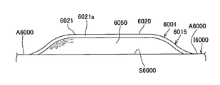
- the bezel member 2021 is formed so as to gradually go downward as it goes from the outer edge portion 2211 to the inner edge portion 2212.
- the bezel member 2021 has an opening 2213 for the image projector 2010 to project an image onto the windshield F2000. That is, the bezel member 2021 forms the entire periphery of the opening 2213.
- the bezel member 2021 may be formed of a synthetic resin containing a light diffusing agent. Further, a light diffusion member (not shown) for diffusing light may be disposed between the bezel member 2021 and the light source unit 2022.
- the outer edge portion 2211 of the bezel member 2021 is arranged so as to be continuous with the facing wall A2000, and the outer surface ( The upper surface) and the outer surface of the facing wall A2000 are arranged so as to be smoothly continuous.
- the opening 2213 of the bezel member 2021 and the opening 2013d of the image projector 2010 are arranged so as to overlap in the vertical direction.
- the bezel member 2021 has the same appearance as the facing wall A2000, for example, so that the difference in reflection on the windshield F2000 between the bezel member 2021 and the facing wall A2000 of the instrument panel I2000 does not stand out. Color adjustment and surface processing are performed.
- the light source unit 2022 is disposed so as to face the entire inner side (lower side) of the outer edge portion 2211 of the bezel member 2021, as shown in FIG.
- the light source unit 2022 includes a light source such as an LED, and can emit light toward the bezel member 2021.
- the light emitted toward the bezel member 2021 passes through the bezel member 2021 and is projected onto the windshield F2000.
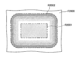
- FIG. 10 is a diagram schematically showing a state in which the light emitted from the light source unit 2022 is projected on the windshield F2000.
- a region R2001 in which an image projected on the windshield F2000 by the image projector 2010 is displayed is surrounded by a region R2002 in which light emitted from the light source unit 2022 is projected.
- the light source unit 2022 is disposed on the inner side (lower side) of the outer edge portion 2211 of the bezel member 2021, the light projected from the light source unit 2022 to the windshield F2000 through the bezel member 2021. Changes so as to gradually become brighter from the inner periphery to the outer periphery of the region R2002.
- the bezel member 2021 is formed of a synthetic resin containing a light diffusing agent, or when a light diffusing member for diffusing light is disposed between the bezel member 2021 and the light source unit 2022
- the light emitted from the light source unit 2022 is diffused by the bezel member 2021 or the light diffusing member, and the unevenness of the light projected on the windshield F2000 due to the arrangement of light sources such as LEDs in the light source unit 2022 is suppressed.
- the bezel body 2020 included in the vehicle display device 2001 includes the light source unit 2022 that is provided inside the bezel member 2021 and emits light toward the bezel member 2021, and the bezel member 2021 is a light source.
- the light emitted from the light source 2022 is transmitted so that the light emitted from the light 2022 is projected onto the windshield F2000.
- various visual effects can be produced using light emitted from the light source unit 2022 other than the image projected onto the windshield F2000 by the image projector 2010.
- the bezel member 2021 is formed using a light-transmitting synthetic resin, and is formed in an annular shape in plan view so as to form the entire periphery of the opening 2213. From this, the image projected on the windshield F2000 by the image projector 2010 is projected so that the light from the light source unit 2022 surrounds the image, and the visibility of the image projected on the windshield F2000 by the image projector 2010 is improved. You can improve or alert the passenger.
- the light source unit 2022 is disposed so as to face the entire inner side (lower side) of the outer edge portion 2211 of the bezel member 2021.
- the light source unit 2022 is disposed on the bezel member 2021.
- the outer edge portion 2211 and the inner edge portion 2212 of the bezel member 2021 may be arranged so as to irradiate light to at least one of the outer edge portion 2211 and the inner edge portion 2212. You may arrange
- the light projected on the windshield F2000 from the light source unit 2022 through the bezel member 2021 changes so as to gradually darken from the inner periphery to the outer periphery of the region R2002.
- the light source unit 2022 may be arranged so as to face the entire inner side (lower side) of the outer edge 2211 and the inner edge 2212 of the bezel member 2021.
- the light projected from the light source unit 2022 onto the windshield F2000 through the bezel member 2021 changes so as to gradually become darker from the inner periphery and outer periphery of the region R2002 toward the intermediate portion.
- the vehicle display device is attached to an instrument panel I2000 of a vehicle V2000, and is used as a head-up display device that performs projection on a windshield F2000.
- An image projector 2010 (FIG. 7, FIG. 8) and a bezel body 2030.
- the bezel body 2030 includes a bezel member 2031 fitted in a hole K2000 provided in a wall A2000 facing the windshield F2000 of the instrument panel I2000, and a light source that emits light toward the bezel member 2031.
- a portion 2022 and a cover 2023 attached to an opening 2313 (described later) provided in the bezel member 2031 are provided.
- the bezel member 2031 is a bezel member having a different shape from the bezel member 2021 of the first embodiment. As shown in FIG. 12, the bezel member 2031 is formed so as to gradually go downward as the distance from the outer edge portion 2311 toward the inner edge portion 2312 increases, and the thickness gradually increases.
- the bezel member 2031 has an opening 2313 for the image projector 2010 to project an image on the windshield F2000. That is, the bezel member 2031 forms the entire periphery of the opening 2313.
- the light source unit 2022 is configured to emit surface light in an annular shape substantially the same as the bezel member 2031 using, for example, an LED array or an organic EL lighting module.
- the bezel member 2031 is disposed so as to face the inner side (lower side) of the bezel member 2031 from the outer edge portion 2311 to the inner edge portion 2312. Accordingly, the light emitted from the light source unit 2022 is emitted toward the entire bezel member 2031.
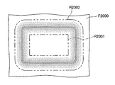
- FIG. 10 is a diagram schematically showing a state in which the light emitted from the light source unit 2022 is projected on the windshield F2000.
- the bezel member 2031 is formed so that the thickness gradually increases from the outer edge portion 2311 toward the inner edge portion 2312. Therefore, in the thickly formed inner edge portion 2312, the light source Light from the portion 2022 is less likely to be transmitted. From this, the light projected from the light source unit 2022 onto the windshield F2000 through the bezel member 2031 changes so as to gradually become brighter from the inner periphery to the outer periphery of the region R2002.
- the bezel member 2031 is formed so that the thickness gradually increases from the outer edge portion 2311 of the bezel member 2031 toward the inner edge portion 2312. For this reason, the light emitted from the light source unit 2022 surrounds the periphery of the image projected onto the region R2001 of the windshield F2000 by the image projector 2010, and the intensity of the light outward from the projected image. Are projected so as to be continuously bright, and the visibility of the image projected on the windshield F2000 by the image projector 2010 can be improved, or the passenger can be alerted.
- the bezel member 2031 is formed so that the thickness gradually increases from the outer edge portion 2311 toward the inner edge portion 2312.
- the bezel member of the present invention is formed from the outer edge portion of the bezel member to the inner edge. It is sufficient that the thickness is formed so as to gradually change toward the portion, and the thickness gradually increases from the outer edge portion 2311A to the inner edge portion 2312A of the bezel member 2031A as in the bezel body 2030A shown in FIG. You may form so that it may become thin.
- the light projected from the light source unit 2022 through the bezel member 2031A onto the windshield F2000 changes so as to gradually darken from the inner periphery to the outer periphery of the region R2002.
- the bezel member may not be formed so that the thickness changes uniformly as it goes from the outer edge portion toward the inner edge portion.
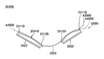
- the bezel body 2030B shown in FIG. It may be formed such that the thickness gradually decreases from the portion 2311B toward the inner edge portion 2312B, and gradually increases from the predetermined portion toward the inner edge portion 2312B.
- the light projected from the light source unit 2022 through the bezel member 2031B onto the windshield F2000 has a dark inner periphery and outer periphery of the region R2002, and gradually increases from the inner periphery and the outer periphery toward the intermediate portion. It has changed to become brighter.
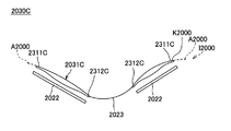
- the bezel member is formed so that the thickness gradually increases from the outer edge portion 2311C of the bezel member 2031C toward the inner edge portion 2312C, and the inner edge portion 2312C from a predetermined location. You may form so that it may become thin gradually as it goes to.
- the light projected from the light source unit 2022 onto the windshield F2000 through the bezel member 2031C has a bright inner periphery and outer periphery of the region R2002, and gradually increases from the inner periphery and the outer periphery toward the intermediate portion. It changes to darken.
- the bezel member of the present invention is not limited to the above-described shape, and is formed so that the thickness is gradually increased and the thickness is gradually decreased toward the outer edge and the inner edge of the bezel member.
- the portion may be formed by being repeated a plurality of times.
- FIGS. 1 and 2 A vehicle display device 3 according to a third embodiment of the present invention will be described with reference to FIGS.
- the same components as those in the first embodiment described above are denoted by the same reference numerals and description thereof is omitted.
- the vehicle display device 3 is attached to the instrument panel I2000 of the vehicle V2000 and is used as a head-up display device that performs projection on the windshield F2000.
- the image projector 2010 (FIG. 7, FIG. 8) and a bezel body 2040.
- the bezel body 2040 includes a bezel member 2041 fitted into a hole K2000 provided in a wall A2000 facing the windshield F2000 of the instrument panel I2000, a light source unit 2022 that emits light toward the bezel member 2041, and a bezel member 2041. And a cover 2023 attached to an opening 2413, which will be described later, provided in (see FIGS. 7 and 8).
- the light source unit 2022 is disposed so as to face the inner side (lower side) of a later-described light transmission portion 2414 of the bezel member 2021.
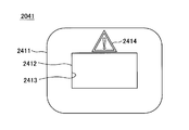
- FIG. 18 is a plan view of the bezel member 2041 as viewed from the back side (the lower side when fitted to the instrument panel I2000). 18 corresponds to the rear side of the vehicle V2000, and the lower side corresponds to the front side of the vehicle V2000.
- the bezel member 2041 has an annular shape in plan view, and is formed so as to gradually go downward as it goes from the outer edge portion 2411 to the inner edge portion 2412. That is, the bezel member 2021 forms the entire periphery of the opening 2213. Further, on the vehicle rear side (upper side in FIG.
- a light transmitting portion 2414 that transmits light from the light source unit 2022 (“Transmits light irradiated from the light source unit” in the claims) Part) ”is provided.
- the light transmission portion 2414 is formed to have a shape of a triangle and an exclamation mark disposed inside the triangle. This shape formed in the light transmission portion 2414 indicates the meaning of alerting the passenger of the vehicle V2000.
- the bezel member 2041 is formed so that portions other than the light transmitting portion 2414 do not transmit light.
- the bezel member 2041 is formed of a transparent material, and a portion other than the light transmission portion 2414 is coated with a light-shielding paint or the like so that a portion other than the light transmission portion 2414 does not transmit light. Yes. Even if the periphery of the edge of the light transmitting portion 2414 is masked or the periphery of the edge of the light transmitting portion 2414 is formed thicker than the light transmitting portion 2414, light may not be transmitted. Good.
- the bezel member 2041 is formed using a material that does not transmit light and has a hole formed in the shape of the light transmitting portion 2414, and the transparent member having the shape of the light transmitting portion 2414 in the hole.
- the light transmitting portion 2414 may be formed by fitting.
- the light transmission portion 2414 is formed in a distorted shape compared to the shape to be displayed so that the shape formed in the light transmission portion 2414 is normally displayed without distortion when projected onto the windshield F2000. It may be. That is, so-called warping may be applied to the shape of the light transmission portion 2414.
- FIG. 19 is a diagram schematically showing a state in which the light emitted from the light source unit 2022 is projected onto the windshield F2000.
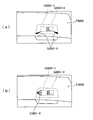
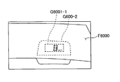
- the light emitted from the light source unit 2022 passes through the light transmitting portion 2414, above the image projected on the windshield F2000 by the image projector 2010 (the portion S2001 shown in FIG. 19). Is projected as a symbol (S2002 portion shown in FIG. 19) having an exclamation point shape.
- the light source unit 2022 detects an approach of a vehicle ahead or a departure from a lane by an ECU (not shown), and the image projector 2010 displays a warning (brake the passenger). Control is performed to irradiate light toward the bezel member 2041 when a “brake!” Prompting) is projected onto the windshield F2000.
- the light emitted from the light source unit 2022 toward the light transmitting portion 2414 is projected on the windshield F2000 as a symbol having an exclamation mark shape inside the triangle, to the passenger. You can call attention to it.
- the light transmitting portion 2414 of the bezel member 2041 has the shape of a symbol indicating the meaning of alerting the passenger on the windshield F2000. For this reason, the light emitted from the light source unit 2022 and transmitted through the light transmitting portion 2414 is projected on the windshield having the symbol shape indicating the alert information, and is projected by the image projector 2010. In addition to the image S2001, warning information can be displayed on the windshield.
- the bezel member 2041 is formed in an annular shape in plan view that forms the entire periphery of the opening 2413, but may be formed having only a part where the light transmission portion 2414 is provided. Good.
- the bezel member 2041 may be formed having only a portion disposed on the vehicle rear side.
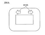
- the light transmissive portion 2414 is formed with an exclamation mark inside the triangle indicating the meaning of alerting the passenger, but the light transmissive portion has predetermined information on the windshield F2000. As long as it has the shape of a symbol indicating, it may have another shape. For example, like the light transmitting portion 2414A in the bezel member 2041A included in the bezel body 2040A shown in FIG. 20 and FIG.
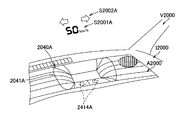
- FIG. 21 is a diagram schematically showing a state in which the light emitted from the light source unit 2022 is projected onto the windshield F2000.
- the light emitted from the light source unit 2022 passes through the light transmission portion 2414 ⁇ / b> A in the left direction above the image projected on the windshield F2000 by the image projector 2010 (S2001A portion shown in FIG. 21).
- a symbol having a shape of an arrow indicating the right direction and an arrow indicating the right direction (S2002A portion illustrated in FIG. 21).
- an arrow symbol is projected on the windshield F2000 and bent at the intersection with respect to the passenger.
- the direction can be shown clearly.
- the image projector 2010 and the bezel body are combined and attached to the vehicle V2000 as a vehicle display device.
- the image projector 2010 and the bezel body are separated. , Each may be separately attached to the vehicle V2000.
- a bezel body capable of producing various visual effects using light and a vehicle display device including the bezel body are provided.
- the vehicle display device (2001) includes an image projector (2010) and a bezel body (2020), and the bezel body (2020) is a bezel member (2021) that is fitted into a hole (K2000) of an instrument panel (I2000).
- a light source unit (2022) that emits light toward the bezel member (2021).
- the bezel member (2021) is light-transmitting and is formed in an annular shape in plan view, and the light source portion (2022) is opposed to the inner side (lower side) of the outer edge portion (2211) of the bezel member (2021).
- the light that is arranged and irradiated from the light source unit (2022) toward the bezel member (2021) is transmitted through the bezel member (2021) and projected onto the windshield (F2000).
- a third invention is a bezel member, a bezel body, and a vehicle display device having the following characteristics.
- a part of or the entire periphery of an opening for projecting an image on the windshield is formed by an image projector disposed in the instrument panel, which is fitted into a wall of the instrument panel facing the windshield.
- a bezel member, A light-transmitting bezel body formed in a frame shape;
- the bezel member, wherein the rib is formed to guide light incident on the rib to the bezel body.
- a bezel body having a bezel member that forms part or all of the vehicle display device includes the bezel member according to any one of (1) to (3), and one or a plurality of light sources arranged to face a light incident portion of the rib of the bezel member.
- a vehicle display device comprising a bezel body characterized by comprising:
- the present invention relates to a bezel member disposed on an instrument panel of a vehicle, a bezel body including the same, and a display device for a vehicle including the same.
- a vehicle display device as a head-up display device that projects an image onto a windshield of a vehicle is provided in an instrument panel (see, for example, Patent Document 31).
- the vehicle display device 3700 described in Patent Document 31 is mounted in an instrument panel I3000 in which an opening H3000 is provided on a wall A3000 facing the windshield F3000. An image is projected onto the glass F3000.
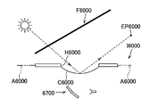
- a transparent cover C3000 that closes the opening H3000 may be provided to prevent dust or moisture from entering the opening H3000. The light is reflected by the cover C3000 and may go directly to the occupant's eye point EP3000, which may cause discomfort.
- a vehicle display device 3800 shown in FIG. 33 is conceivable as a configuration for avoiding that external light travels toward the passenger's eyepoint EP3000.
- the vehicle display device 3800 is provided in the instrument panel I3000.
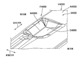
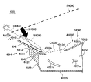
- the instrument panel I3000 has a light-transmitting descending wall portion W that gradually moves downward from the front side to the rear side (left to right in FIG. 33) of the vehicle on the wall A3000 facing the windshield F3000.
- the opening H3000 is provided with a cover C3000 that gradually moves upward as it goes from the front side to the rear side of the vehicle.
- the vehicle display device 3800 projects an image onto the windshield F3000 through the opening H3000.
- Patent Document 31 Japanese Unexamined Patent Application Publication No. 2007-148092 [Summary of Invention] [Problems to be solved by the invention]
- the descending wall portion W3000 is made of a light-transmitting material, and a plate-shaped light guide member 3802 is disposed so as to face the inner surface of the descending wall portion W3000.
- falling wall part W3000 from the inner surface side can be considered. According to this configuration, since the descending wall portion W3000 is brightened so as to reduce the difference in brightness, the reflection on the windshield F3000 can be made inconspicuous, and discomfort given to the passenger can be suppressed.
- ambient Display in order to enhance the projection image in the vicinity of the projection image so that it can be easily recognized by the passenger, or to make the passenger recognize information related to the traveling of the vehicle, so-called ambient Display may be required.
- the space around the vehicle display device illustrated in FIGS. 32 and 33 often does not have enough space, and at present, an image projector or the like for performing the ambient display as described above is added separately. It ’s difficult.
- an object of the present invention is to provide a bezel member capable of performing ambient display while suppressing an occupied space, a bezel body including the bezel member, and a vehicle display device including the bezel body.
- the invention described in (1) includes an image projector that is fitted into a wall facing a windshield of an instrument panel of a vehicle and is disposed in the instrument panel.
- a bezel member that forms part or all of a peripheral edge of an opening for projecting an image on glass, the frame having a light-transmitting bezel body, and the bezel body into the instrument panel And a rib formed so as to protrude, and the rib is formed to guide light incident on the rib to the bezel body.
- the invention described in (2) is characterized in that, in the invention described in (1), the bezel body is a member having a light transmittance of 15% or more and 25% or less.
- the invention described in (3) is characterized in that, in the invention described in (1) or (2), the rib has a shape representing information relating to travel of the vehicle. .
- the invention described in (4) is directed to the bezel member according to any one of (1) to (3) and a light incident portion in the rib of the bezel member. 1 or a plurality of light sources arranged opposite to each other.
- the invention described in (5) is fitted into an opposing wall between an image projector disposed in an instrument panel of a vehicle and a windshield in the instrument panel,
- a display device for a vehicle comprising: a bezel body having a bezel member that forms part or all of a periphery of an opening for an image projector to project an image on the windshield, wherein the bezel member is ( 1.
- a vehicle display device comprising the bezel member according to any one of 1) to (3).
- the bezel body has optical transparency
- the rib formed on the bezel body guides the incident light to the bezel body. It has become.
- an image having a shape along the rib can be reflected in the vicinity of the image projected on the windshield by the image projector. That is, ambient display of the shape along the rib can be performed in the vicinity of the image projected on the windshield by using the reflection on the windshield.
- the rib for the ambient display is formed in the bezel body and takes up no space. Therefore, ambient display can be performed while suppressing the occupied space.
- the bezel body is a member having a light transmittance of 15% or more and 25% or less, the light from the ribs is transmitted while the light source emits light, but the light source does not emit light. Sometimes the ribs are substantially invisible from the passenger, and the appearance can be improved.
- a bezel member, a bezel body, and a vehicle display device according to a first embodiment of the present invention will be described with reference to FIGS.
- FIG. 23 is a perspective view showing a state in which the vehicle display device according to the first embodiment of the present invention is assembled to the instrument panel.
- FIG. 24 is a view of the vehicle display device of FIG. 23 as viewed from the front side of the vehicle.
- 25 is a cross-sectional view of the vehicle display device of FIG.
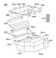
- FIG. 26 is an exploded perspective view of the vehicle display device of FIG.
- FIG. 27 is a diagram illustrating a bezel body included in the vehicle display device of FIG.
- FIG. 28 is a diagram showing a state in which light is incident from the end face of the rib shown in FIG.
- “front / rear, up / down / left / right” corresponds to front / rear, up / down / left / right of the vehicle V3000.
- the vehicle display device 3001 of the present embodiment is attached to the instrument panel I3000 of the vehicle V3000 and is used as a head-up display device that projects an image onto the windshield F3000. Is.
- the vehicle display device 3001 includes an image projector 3010 and a bezel body 3015 as shown in FIGS.
- the image projector 3010 includes a display source 3011 for projecting an image, a reflection unit 3012 that reflects an image from the display source 3011, a synthetic resin casing 3013 that houses the display source 3011 and the reflection unit 3012, and have.
- the housing 3013 includes an upper wall portion 3013a, a lower wall portion 3013b disposed to face the upper wall portion 3013a, and a peripheral wall portion 3013c connected to the peripheral edges of the upper wall portion 3013a and the lower wall portion 3013b.
- the upper wall portion 3013a is provided with an opening 3013d that is disposed so as to overlap with an opening 3210a of a bezel member 3020 described later.
- the image projector 3010 reflects the image projected by the display source 3011 by the reflecting unit 3012 and projects it on the windshield F3000 through the opening 3013d. Thereby, in the passenger
- the bezel body 3015 includes a bezel member 3020, a light guide member 3030, a support member 3040, a lighting window member 3050, a cover 3060, and an LED 3070 as a light source for ambient display described later. Further, the bezel member 3020 has a bezel body 3210 and a rib 3220.
- the bezel body 3210 is made of a synthetic resin that transmits light at a predetermined transmittance.
- the bezel body 3210 has a ring shape in plan view having an opening 3210a at the center and has a shape that gradually goes downward from the outer peripheral edge toward the inner peripheral edge. .
- the bezel body 3210 is formed in a shape that is an upside down version of a hollow, substantially square frustum with an upper end surface and a lower end surface.
- the bezel main body 3210 is fitted into a hole provided in a wall A3000 facing the windshield F3000 of the instrument panel I3000.
- the bezel main body 3210 is fitted into the opposing wall A3000 and forms the entire periphery of the opening 3210a for the image projector 3010 disposed in the instrument panel I3000 to project an image on the windshield F3000.
- the light transmittance in the bezel body 3210 is preferably 15% or more and 25% or less, and more preferably 18% or more and 22% or less.
- the bezel body 3210 has a front bezel portion 3211 that is disposed on the front side of the vehicle V3000 when fitted into the facing wall A3000.
- the front bezel portion 3211 is arranged so as to float upward from the facing wall A3000 so that the front end portion 3211a of the vehicle V3000 forms a gap S3000 with the facing wall A3000 (above the facing wall A3000). To be placed).
- the front bezel portion 3211 has a descending wall portion 3212 that gradually goes downward and reaches the opening 3210a as it goes from the front side to the rear side of the vehicle V3000.
- the bezel main body 3210 When the bezel main body 3210 is fitted into the facing wall A3000, a part of the front side of the outer peripheral edge of the bezel main body 3210 (that is, the front side end 3211a of the vehicle V3000 of the front bezel portion 3211) is lifted above the facing wall A3000. 24 (FIG. 24), and other parts of the outer peripheral edge other than the part are arranged so that the outer surface (upper surface) of the bezel body 3210 and the outer surface of the facing wall A3000 are smoothly connected (FIG. 23). At this time, the opening 3210a of the bezel main body 3210 and the opening 3013d of the image projector 3010 are arranged so as to overlap in the vertical direction.
- the bezel main body 3210 is adjusted to have the same appearance as the facing wall A3000, for example, in order to prevent the difference in reflection on the windshield F3000 between the facing wall A3000 of the instrument panel I3000 and the facing wall A3000. And surface processing.
- the rib 3220 is formed on the inner surface of the bezel body 3210 so as to protrude into the instrument panel I3000.
- the ribs 3220 include edge ribs 3221, skew ribs 3222, front and rear ribs 3223, and arrow-like ribs 3224.
- the edge rib 3221 is a rectangular rib along the edge of the opening 3210a.
- the oblique ribs 3222 are ribs extending radially from the four corners of the opening 3210a toward the periphery of the bezel body 3210.
- the front and rear ribs 3223 are ribs that extend back and forth from the center of the front and rear sides of the opening 3210a toward the periphery of the bezel body 3210.
- the arrow-like rib 3224 is a rib having an arrow-like shape formed adjacent to the left and right of the opening 3210a in FIG.
- Each of the arrow-like ribs 3224 includes a rectilinear portion 3224a that extends from the center of the left and right sides of the opening 3210a to the left and right toward the periphery of the bezel body 3210, and two that extend obliquely from the tip of the rectilinear portion 3224a toward the corner of the opening 3210a.
- the oblique portion 3224b is a rib having an arrow-like shape formed adjacent to the left and right of the opening 3210a in FIG.
- Each of the arrow-like ribs 3224 includes a rectilinear portion 3224a that extends from the center of the left and right sides of the opening 3210a to the left and right toward the periphery of the bezel body 3210, and two that extend obliquely from the tip of the rectilinear
- the rib 3220 is formed of the same resin material as the bezel body 3210 and is integrally formed with the bezel body 3210, and transmits light with the same transmittance as the bezel body 3210.
- the rib 3220 serves as a reinforcing material that reinforces the bezel main body 3210 and also serves to guide light incident from the LED 3070 to the bezel main body 3210 as described later.
- the light guide member 3030 is formed in a substantially rectangular plate shape (FIG. 26) in a plan view using a highly transparent material such as glass, acrylic, polycarbonate, or other synthetic resin, and is formed on the inner surface of the front bezel portion 3211. They are arranged in layers with a slight gap.
- the light guide member 3030 is formed thick on the front side and thin on the rear side, and the portion between the thickly formed portion and the thinly formed portion is from the front to the rear. It is formed so as to become thinner gradually as it goes to.
- the surface of the light guide member 3030 facing downward is formed in a flat shape, and the surface of the downward wall portion 3212 facing upward is inclined in a middle portion in the front-rear direction and gradually descends from the front toward the rear. A surface is formed.
- the light guide member 3030 is formed so as to guide the light that has entered the light incident surface 3030a, which is the front end surface of the vehicle V3000, to the end portion on the rear side and to emit light from the surface on the descending wall portion 3212 side. That is, the light guide member 3030 guides light in the light guide direction from the front end portion where the light incident surface 3030a is located toward the opposite rear end portion. Thus, light can be guided toward the light-transmitting descending wall portion 3212 to illuminate the vicinity of the opening 3210a in the descending wall portion 3212.
- the support member 3040 has a mounting portion 3041 and a pair of leg portions 3042 made of synthetic resin.
- the placement portion 3041 is a portion on which the light guide member 3030 is placed, and is formed in a substantially plate shape whose plan view shape is slightly larger than the plan view shape of the light guide member 3030.
- the mounting portion 3041 is disposed with a space from the inner surface of the front bezel portion 3211, and an end portion 3041 a on the front side of the vehicle V3000 is aligned with an end portion 3211 a of the front bezel portion 3211 in a generally vertical direction.
- both end portions facing in the left-right direction are disposed in contact with the inner surface of the bezel main body 3210.
- the mounting portion 3041 forms an accommodation space K3000 for accommodating the light guide member 3030 between the placement portion 3041 and the front bezel portion 3211.
- the accommodation space K3000 is open toward the gap S3000.
- the light guide member 3030 is disposed such that the light incident surface 3030a faces the gap S3000 through the opening of the accommodation space K3000.
- the pair of leg portions 3042 are portions that connect the placement portion 3041 and the housing 3013 of the image projector 3010, respectively, and forward and upward from both left and right direction front ends of the peripheral wall portion 3013 c of the housing 3013. It extends (FIG. 26).
- the base end of the leg portion 3042 is integrally fixed to the housing 3013, and a fixing portion 3041b provided on the lower surface of the placement portion 3041 is fixed to the distal end.
- the lighting window member 3050 is formed using a highly transparent material such as synthetic resin such as glass, acrylic, and polycarbonate.
- the daylighting window member 3050 is provided so as to seal the opening of the accommodation space K3000 and to take light from the gap S3000 into the accommodation space K3000.
- the lighting window member 3050 is formed in a substantially trapezoidal plate shape (FIGS. 24 and 26) whose plan view is the same as the opening of the accommodation space K3000.
- the lighting window member 3050 has an end 3211a on the front side of the front bezel portion 3211 and an end on the front side of the mounting portion 3041 of the support member 3040 so as to seal the opening of the accommodation space K3000 in which the light guide member 3030 is accommodated.
- the end surface of the bezel body 3210 is in close contact with the inner surface of the bezel body 3210 and the upper surface of the mounting portion 3041.
- the cover 3060 is formed in a thin plate shape using a highly transparent material such as a synthetic resin such as glass, acrylic, or polycarbonate, and is fixed to the periphery of the opening 3210a so as to close the opening 3210a of the bezel body 3210. Attached.
- the cover 3060 is arranged so as to go upward as it goes from the front side to the rear side of the vehicle V3000 (FIG. 25). Thereby, it can suppress that the light which hit the cover 3060 goes directly to a passenger
- a plurality of the LEDs 3070 are arranged along the rib 3220 so as to further face the end face of the rib 3220 facing the bezel body 3210, and light enters the rib 3220 from the end face.
- FIG. 28 is a diagram showing a state in which light enters from the end face of the rib shown in FIG.
- FIG. 28A shows a cross-sectional view of the bezel member 3020 along the longitudinal direction of the rib 3220
- FIG. 28B shows a V3001-V3001 line in FIG.
- a cross-sectional view of the bezel member 3020 is shown.
- a part of the end surface inside the instrument panel I3000 is a light incident portion 3225 into which light from the LED 3070 is incident.
- a reflective layer 3226 that reflects the incident light to the inside of the rib 3220 is formed on the surface other than the light incident portion.
- Examples of such a reflective layer 3226 include a plated layer made of a metal such as aluminum.
- a light emission image having a shape corresponding to the shape of the rib 3220 appears on the surface of the bezel body 3210 on the front panel F side.
- the projection image is emphasized in the vicinity of the projection image from the image projector 3010 so that the passenger can easily recognize it, or information related to traveling of the vehicle V3000 is boarded.
- the following ambient display is made to allow the person to recognize.
- FIG. 29 shows an example of ambient display that emphasizes the projection image G3001-1.
- FIG. 29A shows a first example
- FIG. 29B shows a second example.
- a projected image G3001-2 such as a boundary line between the bezel main body 3210 and the instrument panel I3000 whose brightness difference is reduced by irradiation of the light guide member 3030 is provided around the projection image G3001-1. Is so thin that it is inconspicuous.
- the LED 3070 corresponding to the skewed rib 3222, the front and rear ribs 3223, and the straight portion 3224a of the arrow-like rib 3224 shown in FIG. Is emitted to form a first enhancement ambient image G3001-3.
- An ambient image G3001-4 is formed. Since these ambient images G3001-3 and G1-4 are displayed so as to surround the periphery of the projection image G3001-1, the projection image G3001-1 is emphasized with respect to the scenery outside the window of the windshield F3000. The Rukoto.
- FIG. 30 shows an example of an ambient display that allows the passenger to recognize lane information as information related to the travel of the vehicle V3000.
- the above-mentioned projected image G3001-2 is reflected thinly around the projected image G3001-1.
- FIG. 30 (a) shows an ambient image G3001-5 as a lane guideline indicating a running lane.
- This ambient image G3001-5 has two openings 3210a extending over the front bezel portion 3211 and the descending wall portion 3212 shown in FIGS. 25 and 26 among the four skewed ribs 3222 shown in FIG.
- the LED 3070 corresponding to the two oblique ribs 3222 extending from one corner is made to emit light.
- the ambient image G3001-5 is visually recognized by the passenger as two lines extending forward in the traveling direction of the vehicle V3000, and serves as a lane guide light.
- FIG. 30 (b) shows an ambient image G3001-6 as a direction instruction arrow.
- This ambient image G3001-6 is formed by causing the LED 3070 corresponding to the arrow-like rib 3224 shown in FIG. 27 to emit light.
- the ambient image G3001-6 as an arrow that prompts the user to change to the left lane by causing the LED 3070 corresponding to the left arrow-like rib 3224 in the drawing to emit light among the left and right arrow-like ribs 3224. It is shown.
- the vehicle display device 3001 of the present embodiment which of the ambient images G3001-3 to G3001-6 shown in FIGS. 29 and 30 is displayed is determined by an LED 3070 by a control device (not shown).
- the light emission control is selectively determined.
- the bezel main body 3210 has light transmittance, and the rib 3220 formed on the inner surface of the bezel main body 3210 transmits the incident light. 3210.
- an image having a shape along the rib 3220 can be reflected in the vicinity of the projection image G3001-1 projected onto the windshield F3000 by the image projector 3010. That is, according to this vehicle display device 3001, the ambient display of the shape along the rib 3220 is displayed in the vicinity of the projection image G3001-1 projected on the windshield F3000 using the reflection on the windshield F3000. It can be carried out.
- the rib 3220 for the ambient display is formed on the bezel body 3210 and does not take up space. That is, according to the vehicle display device 3001, ambient display can be performed while suppressing the occupied space.
- the bezel body 3210 is a member having a light transmittance of 15% or more and 25% or less, the LED 3070 transmits light from the rib 3220 while the LED 3070 emits light.
- the rib 3220 becomes substantially invisible from the passenger when the light is not emitted, and the appearance can be improved.
- the rib 3220 has a shape representing lane information as information related to the travel of the vehicle V3000, and the ambient display that allows the passenger to recognize the information related to the travel lane and the lane change. It can be performed.
- the rib shape and the LED arrangement in the bezel body are the same as those in the first embodiment described above except for the above. Therefore, in the following, the second embodiment will be described by paying attention to the differences of the bezel body from the first embodiment, and the description of the same points such as the overall configuration of the vehicle display device will be omitted.
- FIG. 31 is a view for explaining a bezel body according to the second embodiment of the present invention.
- FIG. 31 shows the inner surface side of the bezel body 3085 according to the second embodiment.
- the same components as those of the bezel body 3015 according to the first embodiment shown in FIG. 27 are denoted by the same reference numerals as those in FIG. A duplicate description of elements is omitted.
- the rib 3910 of the bezel member 3090 has a bezel body 3210 from four corners of the edge rib 3221 along the edge of the opening 3210a also shown in FIG. And oblique ribs 3222 extending radially toward the periphery of the.
- the LED 3100 is arranged in a side edge manner in which light enters the oblique rib 3222 from each distal end surface, one by one near the distal end surface of the bezel main body 3210 in each oblique rib 3222. Yes.
- a reflection layer (not shown) is formed in addition to the front end surface of each skew rib 3222.
- the incident light is guided from the oblique ribs 3222 to the edge ribs 3221 while being confined in the ribs 3910 and guided to the bezel body 3210.
- a light emission image having a shape corresponding to the shape of the rib 3910 appears on the surface of the bezel body 3210 on the front panel F side.
- ambient display is performed in the vicinity of the projection image from the image projector 3010.
- an enhancement ambient image equivalent to the second enhancement ambient image G3001-4 shown in FIG. 29B is formed.
- ambient display can be performed while suppressing the occupied space.
- the number of LED3100 is restrained by employ
- the LED 3070 disposed to face the end surface of the rib 3220 facing the bezel body 3210 and the tip surface of the skew rib 3222 are disposed to face each other.
- An LED 3100 is illustrated.
- the arrangement of the LEDs is not limited to these arrangements.
- the LED may be arranged so as to face the side surface rising from the inner surface of the bezel body 3210 at the rib 3220.
- the arrangement of the LED may be any arrangement that allows light to enter each rib 3220, and does not ask the specific arrangement.
- the rib 3220 includes the edge rib 3221, the skew rib 3222, the front and rear ribs 3223, and the arrow-like rib 3224, and an ambient display that emphasizes the projection image G3001-1 and the vehicle V3000.
- the ambient display that allows the passenger to recognize the information related to the traveling can be selectively performed.
- the rib 3910 includes the edge rib 3221 and the skew rib 3222, and is configured to perform ambient display that emphasizes the projection image G3001-1.
- the shape and configuration of the rib are not limited to these.
- the rib may be composed of only the edge rib 3221 or the skewed rib 3222, or may be composed of only the arrow-like rib 3224.
- the shape and configuration of the rib are not particularly limited as long as it corresponds to the desired ambient display.
- An image projector (3010) fitted in a wall (A3000) facing the windshield (F3000) in the instrument panel (I3000) of the vehicle (V3000) and disposed in the instrument panel (I3000) is a windshield.
- a bezel member (3020) that forms part or all of the periphery of the opening (2210a) for projecting an image on (F3000), and the bezel member (3020) is formed in a frame shape.
- a fourth invention is a vehicle display device having the following characteristics.
- a light-transmitting descending wall portion gradually moving downward as it goes from the front to the rear of the vehicle and an opening adjacent to the lower end of the descending wall portion are arranged in the instrument panel provided on the wall facing the windshield.
- a vehicle display device An image projector disposed below the opening and projecting an image onto the windshield through the opening;
- a light guide member that is disposed inside the descending wall portion and guides light toward the descending wall portion;
- a support member provided to project forward from the image projector so as to support the light guide member from below,
- the vehicle display device wherein the support member is provided with a breaking portion that is broken so that the light guide member falls due to a force applied at the time of a collision of the vehicle.
- the support member includes a placement portion on which the light guide member is placed, and a leg portion that connects the placement portion and the image projector.
- the placing portion is formed with the break portion along a left-right direction of the vehicle at a central portion in the front-rear direction of the vehicle.
- the break portion is formed in a position near the position where the leg portion is connected to the image projector or the position where the leg portion is connected to the mounting portion described above (2) or (3)
- the fracture portion is a wedge-shaped notch that gradually narrows from the surface toward the inside.
- the present invention relates to a display device for a vehicle that performs projection on a windshield. [Background technology]
- a vehicle display device as a head-up display device that projects an image onto a windshield of a vehicle is provided in an instrument panel (see, for example, Patent Document 41).
- the vehicle display device 4700 described in Patent Document 41 is mounted in an instrument panel I4000 in which an opening H4000 is provided on a wall A4000 facing the windshield F4000, and the windshield through the opening H4000.
- An image is projected onto F4000.
- a transparent cover C4000 is provided in the opening H4000 in order to prevent dust or moisture from entering the opening H4000, external light such as sunlight is not emitted.
- an unpleasant feeling is given by reflecting on the cover C4000 and reaching the occupant's eye point EP4000.
- the vehicle display device 4800 is provided in the instrument panel I4000.
- This instrument panel I4000 has an opening H4000 adjacent to the lower wall of the light-transmitting descending wall portion W4000 and the descending wall portion W4000, which gradually goes downward as it goes from the front to the rear of the vehicle. And are provided.
- the opening H4000 is provided with a cover C4000 that gradually moves upward as it goes from the front to the rear of the vehicle.
- the vehicle display device 4800 projects an image onto the windshield F4000 through the opening H4000.
- Patent Document 41 JP 2007-148092 A [Summary of Invention] [Problems to be solved by the invention]
- the descending wall portion W4000 becomes dark, and the brightness difference between the cover C4000 and the vicinity of the opening H4000 of the descending wall portion W4000.
- the problem that the reflection on the windshield F4000 becomes conspicuous due to the increase in the size of the windshield is considered.
- the descending wall portion W4000 is made of a light-transmitting material, and a light guide member 4802 that guides the incident light and emits it is disposed inside (lower side) of the descending wall portion W4000.
- the descending wall portion W4000 becomes bright, reduces the difference in brightness between the cover C4000 and the vicinity of the opening H4000 of the descending wall portion W4000, and makes the reflection on the windshield F4000 inconspicuous. Discomfort can be suppressed.
- the light guide member 4802 is formed using a relatively hard material such as resin or glass, in consideration of safety, for example, the vehicle is a collision object such as a pedestrian. It has been required to reduce the impact on the collision object when it collides.
- the present invention focuses on the above-described problems, and provides a vehicle display device that can make the reflection on the windshield inconspicuous and can reduce the impact on a collision object.
- the purpose is to do.
- the invention described in (1) includes a light-transmitting descending wall portion that gradually goes downward from the front to the rear of the vehicle, and an opening adjacent to the lower end of the descending wall portion.
- a vehicle display device disposed in an instrument panel provided on a wall facing the windshield, and is disposed below the opening and projects an image onto the windshield through the opening.
- a light guide member that is disposed inside the descending wall portion and guides light toward the descending wall portion, and is provided to project forward from the image projector so as to support the light guide member from below.
- a support member provided with a breaking portion that is broken so that the light guide member falls due to a force applied when the vehicle collides. is there
- the support member in the invention described in (2), in the invention described in (1), includes a mounting unit on which the light guide member is mounted, the mounting unit, and the image projector. And a leg portion to be connected.
- the invention described in (3) is the invention described in (2), wherein the breaking portion is formed in the center portion in the front-rear direction of the vehicle along the left-right direction of the vehicle. It is characterized by being.
- the leg portion in the invention described in (2) or (3), includes a position where the image projector is connected to the leg portion or the mounting portion described in the leg portion.
- the rupture portion is formed in the vicinity of a position continuous with.
- the invention described in (5) is characterized in that, in the invention described in (3) or (4), the fracture portion is a wedge-shaped notch that gradually becomes narrower from the surface toward the inside. To do. [The invention's effect]
- the support member is provided so as to protrude forward from the image projector so as to support the light guide member from below, and the support member is subjected to a force applied when the vehicle collides. Since a breaking portion is provided that breaks so that the light guide member falls, for example, when a collision object such as a pedestrian's head hits the light guide member when the vehicle collides, the light guide member is guided. Before the member is broken, the support member breaks to absorb the impact. For this reason, the impact on the collision object can be reduced.
- the light guide member since the light guide member is placed on the placement portion of the support member, the light guide member can be easily dropped when the support member breaks.
- the breaking portion is formed along the left-right direction of the vehicle in the center portion in the front-rear direction of the vehicle, the breaking portion is broken. Therefore, when the vehicle collides, the mounting portion breaks and absorbs the impact before the light guide member is destroyed. It is possible to reduce the impact on the collision object.
- the leg portion is formed with the fracture portion in the vicinity of the position where the leg portion is connected to the image projector or the position where the leg portion is connected to the placement portion,
- the rupture part breaks, the rupture part is provided at a position where the light guide member is easily dropped, and when the vehicle collides, the leg part ruptures before the light guide member is destroyed. Can be absorbed, and the impact on the collision object can be reduced.
- the fracture portion is a notch formed in a wedge shape, stress tends to concentrate, and it becomes easier to break when force is applied at the time of collision. Thus, the support member can be more reliably broken at the notch.
- the vehicle display device 4001 of this embodiment is attached to the inside of the instrument panel I4000 of the vehicle V4000 and is used as a head-up display device that projects onto the windshield F4000.
- the instrument panel I4000 includes a light-transmitting descending wall portion W4000 that gradually goes downward from the front of the vehicle V4000 toward the rear of the wall A4000 facing the windshield F4000. And an opening H4000 adjacent to the lower end of the descending wall W4000.
- a transparent thin plate-like cover C4000 is attached to the opening H4000 so as to gradually move upward as it goes from the front side to the rear side of the vehicle V4000, thereby preventing dust, moisture, and the like from entering the opening H4000.
- the up-down direction, the front-rear direction, and the left-right direction correspond to the up-down direction, the front-rear direction, and the left-right direction in the vehicle V4000.
- the vehicular display device 4001 is disposed inside the image projector 4002 that projects an image onto the windshield F4000 through the opening H4000 and the inside (lower side) of the descending wall portion W4000, and guides light toward the descending wall portion W4000.
- a member 4003 and a support member 4004 provided to protrude forward from the image projector 4002 so as to support the light guide member 4003 from below are configured.
- the image projector 4002 includes a display source 4021a for projecting an image, a reflection unit 4021b that reflects an image from the display source 4021a, and a housing 4022 in which the display source 4021a and the reflection unit 4021b are accommodated. ing.
- the housing 4022 is formed in a box shape using a synthetic resin, and has a top wall 4022a, a bottom wall 4022b, a peripheral wall 4022c, and an opening 4022d.
- the opening 4022d is arranged to overlap the opening H4000 provided in the facing wall A4000 in the vertical direction.
- the image projector 4002 reflects the image projected by the display source 4021a by the reflection unit 4021b and projects it onto the windshield F4000 through the opening 4022d. Thereby, the passenger of vehicle V4000 recognizes as an image displayed on windshield F4000.
- the light guide member 4003 is formed in a substantially rectangular plate shape in plan view using a highly transparent material such as glass or resin. Further, in a cross-sectional view in the front-rear direction, the front side is formed thicker, the rear side is formed thinner, and the part between the thicker part and the thinner part gradually becomes thinner from the front toward the rear. Is formed. In other words, as shown in FIG. 37, the surface of the light guide member 4003 on the side of the mounting portion 4041 described later is formed in a flat shape, and the surface on the side of the descending wall portion W4000 is from the front to the rear in the middle portion in the front-rear direction. An inclined surface that gradually descends as it goes is formed.
- the light guide member 4003 receives external light such as sunlight at the end surface on the front side of the vehicle, guides it to the end portion on the rear side of the vehicle, and lowers light transmittance. It is provided to emit light toward the wall W4000. Thereby, the opening H4000 vicinity of descending wall part W4000 can be illuminated from an inner side. With such a configuration, the vicinity of the opening H4000 of the descending wall portion W4000 that is not irradiated with external light can be brightened by illuminating from the inside, and the difference in brightness between the cover C4000 and the vicinity of the opening H4000 of the descending wall portion W4000 is reduced. It is possible to suppress discomfort to the passenger by making the reflection on the glass F4000 inconspicuous.
- the support member 4004 is formed using a synthetic resin, and includes a placement portion 4041 on which the light guide member 4003 is placed, and two legs 4042 that connect the placement portion 4041 and the image projector 4002. is doing.
- the mounting portion 4041 is formed in a plate shape, and is disposed to be inclined along the descending wall portion W4000.
- the placement portion 4041 is bent so that the rear end portion is along the upper surface wall 4022a of the housing 4022.
- the two leg portions 4042 are formed integrally with the housing 4022 of the image projector 4002, and one end extends forward and upward from both left and right ends of the front surface of the peripheral wall 4022c. It is bent upward and the other end is fixed to a fixing portion 4411 described later of the mounting portion 4041.
- fixing portions 4411 for fixing the other end side of the leg portion 4042 are provided at both ends in the left-right direction on the back surface of the mounting portion 4041 (the surface opposite to the surface on which the light guide member 4003 is mounted). It has been. As shown in FIGS. 37 and 38, a wedge-shaped notch 4412 that is gradually narrowed inward in a cross-sectional view in the front-rear direction is formed in the center in the front-rear direction of the mounting portion 4041. . The notch 4412 is formed over the entire length of the mounting portion 4041 in the left-right direction. In addition, the fixing portion 4411 is provided on the rear side of the notch 4412.
- a wedge-shaped notch 4421 gradually narrows inward in the vicinity of one end of the leg 4042 (portion connected to the housing 4022 of the image projector 4002). Is formed.
- the notch 4421 is formed over the entire length of the leg 4042 in the left-right direction.
- the notches 4412 and 4421 are provided as rupture portions that are broken by a force applied when the vehicle V4000 collides, and are set so as not to be broken by vibration or the like during normal traveling.
- the support member 4004 is provided so as to protrude forward from the image projector 4002 so as to support the light guide member 4003 from below, and the support member 4004 is subjected to a force applied when the vehicle V4000 collides. For example, when a collision object such as a pedestrian's head hits the light guide member 4003 when the vehicle V4000 collides because the light guide member 4003 is broken so that the light guide member 4003 falls. The support member 4004 breaks and absorbs the impact before the light guide member 4003 is broken. For this reason, the impact on the collision object can be reduced.
- the light guide member 4003 is placed on the placement portion 4041 of the support member 4004, the light guide member 4003 can be easily dropped when the support member 4004 is broken.
- the mounting portion 4041 causes the light guide member 4003 to drop when the notch 4412 breaks.
- the notch 4412 is provided at an easy position, and when the vehicle V4000 collides, the mounting portion 4041 can be broken and absorb the impact before the light guide member 4003 is broken, Impact on objects can be reduced.
- the leg 4042 is provided with a notch 4421 in the vicinity of a position where the leg 4042 is connected to the housing 4022 of the image projector 4002, so that the notch 4421 is broken, whereby the light guide member 4003 is attached.
- a notch 4421 is provided at a position where it is easy to drop, and when the vehicle V4000 collides, the leg portion 4042 can be broken before the light guide member 4003 is broken to absorb the impact, The impact on the collision object can be reduced.
- the notches 4412 and 4421 are formed in a wedge shape, it becomes easier to break when a force is applied at the time of collision, and the support member 4004 can be broken more reliably at the notches 4412 and 4421.
- the notches 4412 and 4421 are provided as portions (breaking portions) that are broken by the force applied when the vehicle V4000 collides, but the light guide member 4003 falls due to the force applied when the vehicle V4000 collides.
- the broken portion is formed in a shape in which stress other than the notch is likely to concentrate, or the portion 4041 and the leg 4042 are fixed. In this case, it may be formed using a material that breaks first.
- the support member 4004 is provided with the notches 4412 and 4421.
- the support member 4004 may be configured to be broken by a force applied when the vehicle V4000 collides.
- 4421 may be provided.
- the position where the notch is provided is not limited to the central portion in the front-rear direction of the vehicle V4000 of the mounting portion 4041 or the vicinity of the position where the leg 4042 is connected to the housing 4022 of the image projector 4002, for example, the leg 4042 A notch may be provided in the vicinity of the other end (in the vicinity of the position where the leg 4042 is connected to the mounting portion 4041).
- the notch 4412 is provided in the mounting part 4041 in the vicinity of the position where the mounting part 4041 and the leg part 4042 are continuous, but the leg part 4042 may be provided with a notch. .
- the leg portion 4042 of the support member 4004 is provided integrally with the image projector 4002.
- the leg portion 4042 may be provided so as to protrude forward from the image projector 4002, and separately.
- the formed leg 4042 may be fixed to the image projector 4002.
- the inclined surface part and opening were formed in facing wall A4000 with the windshield of instrument panel I4000, the separate surface which has an inclined surface part and opening in the hole provided in facing wall A4000. You may provide an inclined surface part and opening by fitting a member.
- the present invention provides a display device for a vehicle that can make a reflection on a windshield inconspicuous and can reduce an impact on a collision object.
- the vehicle display device (4001) is attached to the inside of an instrument panel (I4000) provided with a descending wall portion (W4000) and an opening (H4000), and includes an image projector (4002), a descending wall portion ( A light guide member (4003) that guides light toward W4000) and a support member (4004) that supports the light guide member (4003) from below.
- the support member (4004) includes a placement portion (4041) on which the light guide member (4003) is placed, a leg portion (4042) that connects the placement portion (4041) and the image projector (4002), and have.
- the mounting portion (4041) and the leg portion (4042) are formed with wedge-shaped notches (4412, 4421) that are broken by the force applied when the vehicle (V4000) collides.
- a fifth invention is a bezel body and a vehicle display device having the following characteristics.
- An image projector that is fitted into a wall of a vehicle instrument panel facing the windshield and disposed in the instrument panel forms part or all of the periphery of an opening for projecting an image on the windshield.
- a bezel body having a bezel member The bezel member has a front bezel portion disposed on the front side of the vehicle with respect to the opening;
- the front bezel portion has a light-transmitting descending wall portion that gradually goes downward toward the opening as it goes from the front side to the rear side of the vehicle,
- a light guide member that is formed in a plate shape and is disposed on the inner surface of the front bezel portion and guides light to the descending wall portion; a support member that is attached to the bezel member and supports the light guide member; Further comprising
- the bezel body comprising the bezel member, the light guide member, and the support member integrally.
- a light source part arranged to face the front bezel part across the light guide member, and further irradiating light toward the front bezel part through the light guide member;
- a vehicle display device comprising a bezel body having a bezel member forming part or all of the part, The vehicle display device, wherein the bezel body is constituted by the bezel body described in (1) or (2).
- the present invention relates to a bezel body disposed on an instrument panel of a vehicle and a vehicle display device including the bezel body.
- a vehicle display device as a head-up display device that projects an image onto a windshield of a vehicle is provided in an instrument panel (see, for example, Patent Document 51).
- the vehicle display device 5700 described in Patent Document 51 is mounted in an instrument panel I5000 having an opening H5000 provided on a wall A5000 facing the windshield F5000, and is connected to an image projector 5701.
- an image is projected onto the windshield F5000 through the opening H5000.
- a transparent cover C5000 that closes the opening H5000 may be provided in order to prevent dust or moisture from entering the opening H5000.
- the light may be reflected by the cover C5000 and head toward the passenger's eye point EP5000, which may cause discomfort.
- a vehicle display device 5800 shown in FIG. 47 is conceivable as a configuration for avoiding that external light travels toward the passenger's eye point EP5000.
- This vehicular display device 5800 is provided in an instrument panel I5000, and includes an image projector 5801 and a bezel member 5802.
- the bezel member 5802 is fitted into a hole K5000 provided in a wall A5000 facing the windshield F5000 of the instrument panel I5000.
- the bezel member 5802 is adjacent to the lower end and the rear side of the light-transmitting descending wall portion 5821 and the descending wall portion 5821 that gradually move downward from the front side to the rear side (from left to right in FIG. 47) of the vehicle.
- An opening 5822 is provided.
- the opening 5822 is provided with a cover C5000 that gradually rises upward from the front side of the vehicle toward the rear side.
- the vehicle display device 5800 uses the image projector 5801 to display an image through the opening 5822 of the bezel member 5802. Project onto glass F5000.
- the descending wall portion 5821 is provided and the vehicle front side of the cover C5000 is located below the rear side, it is possible to make it difficult for outside light to reach the cover C5000 and to cover the cover C5000. It is possible to suppress the outside light reflected on the vehicle from traveling toward the passenger's eye point EP5000.
- Patent Document 51 Japanese Patent Application Laid-Open No. 2007-148092 [Summary of Invention] [Problems to be solved by the invention]
- the descending wall portion 5821 of the bezel member 5802 is made of a light-transmitting material, and the light guide member 5803 is disposed so as to face the inner surface of the descending wall portion 5821, and external light is lowered by the light guide member 5803.
- the structure which guides to the location near the opening 5822 of the part 5821 and illuminates the descending wall part 5821 from the inner surface side can be considered. According to this configuration, since the descending wall portion 5821 is brightened so that the difference in brightness is reduced, the reflection on the windshield F5000 can be made inconspicuous, and the discomfort given to the passenger can be suppressed. it can.
- the vehicle display device 5800 includes the light guide member 5803 and the parts used to support the light guide member 5803, the workability at the time of attachment is reduced due to an increase in the number of parts. was there.
- An object of the present invention is to provide a vehicle display device provided. [Means for solving problems]
- the invention described in (1) is directed to an image projector that is fitted in a wall facing a windshield in an instrument panel of a vehicle and disposed in the instrument panel.
- a bezel body having a bezel member that forms part or all of a peripheral edge of an opening for projecting an image on the front bezel portion, wherein the bezel member is disposed on the front side of the vehicle with respect to the opening
- the front bezel portion has a light-transmitting descending wall portion that gradually goes downward and reaches the opening as it goes from the front side to the rear side of the vehicle, and is formed in a plate shape.
- a light guide member disposed on the inner surface of the bezel portion and guiding light to the descending wall, and a support member attached to the bezel member and supporting the light guide member. It has a et al., And the bezel member, and the light guide member, wherein the supporting member is a bezel body, characterized in that integrally has a.
- the invention described in (2) is the invention described in (1), wherein the light guide member is disposed so as to face the front bezel portion, and the light guide member is directed toward the front bezel portion.
- a light source unit that emits light, and at least a portion of the front bezel facing the light source unit is light transmissive.
- the image projector is fitted into a facing wall between the image projector disposed in the instrument panel of the vehicle and the windshield in the instrument panel, and the image projector has an image on the windshield.
- the bezel member, the light guide member, and the support member attached to the bezel member and supporting the light guide member are integrally provided, the bezel member, The light guide member and the support member can be integrally attached to the instrument panel, and the workability when attaching the bezel body can be improved.
- the light source unit further includes a light source unit that is disposed so as to face the front bezel part with the light guide member interposed therebetween, and that emits light toward the front bezel part through the light guide member, Since the portion facing the light source unit in the front bezel portion is light transmissive, the light emitted from the light source unit can be projected onto the windshield through the light guide member and the front bezel portion. In addition to the image projected on the windshield, various visual effects can be produced using light emitted from the light source unit.
- the bezel body described in (1) or (2) since the bezel body described in (1) or (2) is provided, the bezel member, the light guide member, and the support member can be integrally attached to the instrument panel. The workability at the time of attaching the vehicle display device can be improved.
- a vehicle display device 5001 according to this embodiment is attached to an instrument panel I5000 of a vehicle V5000 and is used as a head-up display device that performs projection onto a windshield F5000, and includes an image projector 5010 and a bezel body. 5020.
- the up-down direction, the front-rear direction, and the left-right direction correspond to the up-down direction, the front-rear direction, and the left-right direction in the vehicle V5000.
- the image projector 5010 includes a display source 5011, a reflection unit 5012 that reflects an image from the display source 5011, a housing 5013 in which the display source 5011 and the reflection unit 5012 are housed, and a bezel body.
- Two legs 5014 for fixing 5020 are provided.
- the housing 5013 is formed in a box shape using a synthetic resin, and includes a top wall 5013a, a bottom wall 5013b, a peripheral wall 5013c, and an opening 5013d provided in the top wall 5013a.
- the opening 5013d is disposed so as to overlap with an opening 5212 of a bezel member 5021 described later.
- Two leg portions 5014 are formed integrally with the housing 5013, one end is extended forward and upward from both ends in the left-right direction of the front surface of the housing 5013, and is bent upward at the extended upper end. The other end is fixed to a fixing portion 5233 of a support member 5023 described later.
- the image projector 5010 reflects the image projected by the display source 5011 by the reflection unit 5012 and projects it on the windshield F5000 through the opening 5013d. Thereby, the passenger of vehicle V5000 recognizes as an image displayed on windshield F5000.
- the bezel body 5020 is a bezel member 5021 that is fitted into the hole K5000 of the instrument panel I5000, a light guide member 5022 that guides light toward the bezel member 5021, and a support that is attached to the bezel member 5021 and supports the light guide member 5022. It has a member 5023, a light source portion 5024 for irradiating light toward the bezel member 5021 through the light guide member 5022, and a cover 5025 attached to an opening 5212 described later provided in the bezel member.
- the bezel member 5021 is formed in a ring shape in plan view using a light-transmitting synthetic resin, and the front bezel portion 5211 disposed on the front side of the vehicle V5000 and the image projector 5010 for projecting an image onto the windshield F5000.
- An opening 5212 and a fitting claw portion 5213 for fitting to the support member 5023 are formed. That is, the inner peripheral edge of the bezel member 5021 forms an opening 5212.
- the front bezel portion 5211 has a descending wall portion 5211a that gradually goes downward and reaches the opening 5212 from the front side to the rear side of the vehicle V5000.
- the front end is arranged so as to float above the opposing wall A5000, and the outer surface (upper surface) of the bezel member 5021 and the outer surface of the opposing wall A5000 are smoothly continuous with each other part of the outer peripheral edge other than the part. Placed in.
- the opening 5212 of the bezel member 5021 and the opening 5013d of the image projector 5010 are arranged so as to overlap in the vertical direction.
- the bezel member 5021 has the same appearance as the facing wall A5000, for example, so that the difference in reflection on the windshield F5000 between the bezel member 5021 and the facing wall A5000 of the instrument panel I5000 is not noticeable. Color adjustment and surface processing are performed.
- the light guide member 5022 is formed in a rectangular plate shape in plan view using a highly transparent material such as glass or resin, and is disposed so as to overlap the inner surface (lower side) of the front bezel portion 5211. Further, in a cross-sectional view in the front-rear direction, the front side is formed thicker, the rear side is formed thinner, and the part between the thicker part and the thinner part gradually becomes thinner from the front toward the rear. Is formed. Specifically, as shown in FIG. 44, the surface of the light guide member 5022 on the mounting portion 5231 side, which will be described later, is formed in a flat shape, and the surface on the front bezel portion 5211 side is an intermediate portion in the front-rear direction from the front. An inclined surface that gradually descends toward the rear is formed.
- the light guide member 5022 is provided so that the front end portion is located on the inner side (lower side) of a part of the front side that is raised above the facing wall A5000 of the bezel member 5021. The side end is exposed and arranged so as to receive external light such as sunlight. As indicated by an arrow L5000 in FIG. 44, the light guide member 5022 receives external light, guides it to the vehicle rear side end portion, and emits light toward the light-transmitting descending wall portion 5211a. Is provided. Accordingly, the vicinity of the opening 5212 of the descending wall portion 5211a can be illuminated.
- the vicinity of the opening 5212 of the descending wall portion 5211a that is not irradiated with external light can be brightened by illuminating from the inside, and the brightness difference between the cover 5025 and the vicinity of the opening 5212 of the descending wall portion 5211a is reduced to reduce the front. It is possible to suppress discomfort to the passenger by making the reflection on the glass F5000 inconspicuous.
- the support member 5023 is formed using a synthetic resin, and a placement portion 5231 on which the light guide member 5022 is placed, a fitting receiving portion 5232 in which the fitting claw portion 5213 of the bezel member 5021 is fitted, and an image And a fixing portion 5233 to which the leg portion 5014 of the projector 5010 is fixed.
- the placement portion 5231 is formed in a plate shape, and is inclined along the front bezel portion 5211. As shown in FIG. 44, the mounting portion 5231 is bent so that the rear end portion is along the upper surface wall 5013 a of the housing 5013.
- the bezel member 5021, the light guide member 5022, and the support member 5023 can be integrated by fitting the fitting claw portion 5213 of the bezel member 5021 with the fitting receiving portion 5232 of the support member 5023. it can.
- the light source unit 5024 is disposed so as to face the front bezel part 5211 with the light guide member 5022 interposed therebetween, and has a light source 5241 such as an LED, and the front bezel part through the light guide member 5022. Light can be emitted toward 5211.
- the light source unit 5024 detects when an ECU (not shown) detects an approaching vehicle or a lane departure, and the image projector 5010 projects a warning display S5001 on the windshield.
- the light is controlled to be emitted toward the front bezel portion 5211.
- the passenger notices that the light emitted from the light source unit 5024 toward the front bezel portion 5211 is reflected on the windshield F5000 and the warning display S5001 is projected. It can be made easier and visibility can be improved.
- a light source 5241 can be provided in the light source unit 5024 by changing the color and arrangement of the light sources in accordance with a desired visual effect.
- the cover 5025 is formed in a thin plate shape that matches the size of the opening 5212 of the bezel member 5021 using a transparent synthetic resin.
- the cover 5025 is attached to the opening 5212 of the bezel member 5021 so as to gradually move upward as it goes from the front side to the rear side of the vehicle, and dust and moisture can be prevented from entering the opening 5212.
- the bezel body 5020 is assembled and integrated as shown in FIG. Further, the display device 5001 for the vehicle is obtained by combining the image projector 5010 and the bezel body 5020 integrated in advance.
- the vehicle display device 5001 assembled as described above is fitted into the hole K5000 provided in the facing wall A5000 of the instrument panel I5000, whereby the attachment of the vehicle display device 5001 is completed as shown in FIG.
- the bezel body 5020 integrally includes the bezel member 5021, the light guide member 5022, and the support member 5023 attached to the bezel member 5021 and supporting the light guide member.
- the bezel member 5021, the light guide member 5022, and the support member 5023 can be integrally attached to the instrument panel I5000, and workability when attaching the bezel body 5020 and the vehicle display device 5001 can be improved. .
- the light guide member 5022 is disposed so as to face the front bezel portion 5211 with the light guide member 5022 interposed therebetween, and further includes a light source unit 5024 that emits light toward the front bezel portion 5211 through the light guide member 5022. Since it has transparency, light emitted from the light source unit 5024 can be projected onto the windshield F5000 through the light guide member 5022 and the front bezel portion 5211, and the image projector 5010 projects onto the windshield F5000.
- Various visual effects such as, for example, improving the visibility of the image projected by the image projector 5010 can be produced using light emitted from the light source unit 5024 in addition to the image.
- the image projector 5010 and the bezel body 5020 are combined and attached to the vehicle V5000 as the vehicle display device 5001, but the image projector 5010 and the bezel body 5020 are separated. Each of them may be separately attached to the vehicle V5000.
- the bezel member 5021 and the support member 5023 are fitted by the fitting claw portion 5213 and the fitting receiving portion 5232, but the bezel member 5021 and the support member 5023 are integrally provided.
- it may be fixed by other fixing methods such as fixing with bolts.
- the bezel member 5021 is formed in an annular shape in plan view to form the entire periphery of the opening 5212.
- the bezel member 5021 forms a part of the periphery of the opening 5212 (i.e., A portion having only the front bezel portion 5211) and forming the other portion of the periphery of the opening 5212 may be formed integrally with the instrument panel I5000.
- the bezel member 5021 has light transmittance. However, it is sufficient that at least a portion facing the light source unit 5024 has light transmittance. Further, in a bezel body that does not include the light source unit 5024, it is sufficient that at least the descending wall unit 5211a has light transmittance.
- the present invention provides a bezel body that can make the reflection on the windshield inconspicuous and can improve workability during attachment, and a vehicle display device including the bezel body.
- the bezel body (5020) of the vehicle display device (5001) includes a bezel member (5021), a light guide member (5022), a support member (5023) of the light guide member (5022), and a light guide member (5022). And a light source part (5024) for irradiating light toward the bezel member (5021).
- the bezel member (5021) has a light-transmitting front bezel portion (5211) having a descending wall portion (5211a) gradually moving downward as it goes from the front side to the rear side, and the image projector (5010) projects an image.
- An opening (5212) for fitting, and a fitting claw (5213) for fitting to the support member (5023), and the fitting claw (5213) is fitted to the support member (5023). It has a fitting receiving part (5232).
- a sixth invention is a bezel body, an instrument panel, and a vehicle display device having the following features.
- a bezel having a bezel member that forms a peripheral edge of an opening for projecting an image onto the windshield by an image projector that is fitted in a wall facing the windshield of the instrument panel of the vehicle and disposed in the instrument panel Body, A bezel body, wherein the bezel member is integrally provided with a transparent cover for closing the opening.
- An image projector is disposed inside, and an opening for projecting an image onto the windshield by the image projector is an instrument panel provided on a wall facing the windshield, An instrument panel, wherein a transparent cover for closing the opening is integrally provided on the opposing wall.
- An image projector disposed in an instrument panel of a vehicle and a front wall of the instrument panel are fitted into a facing wall to form a peripheral edge of an opening for the image projector to project an image on the windshield.
- a vehicle display device comprising: a bezel body having a bezel member for The vehicle display device, wherein the bezel body is constituted by the bezel body described in (1) or (2).
- the present invention relates to a bezel body disposed on an instrument panel of a vehicle, an instrument panel, and a vehicle display device including the bezel body.
- a vehicle display device as a head-up display device that projects an image onto a windshield of a vehicle is provided in an instrument panel (see, for example, Patent Document 61).
- the vehicle display device 6700 described in Patent Document 61 is mounted in an instrument panel I6000 having an opening H6000 provided on a wall A6000 facing the windshield F6000, and the front panel through the opening H6000. An image is projected onto the glass F6000.
- an image projection port is provided in a case (not shown) so as to overlap this opening H6000.
- a transparent cover C6000 that closes the projection port in order to prevent dust or moisture from entering the case from the image projection port may be provided. External light such as light may be reflected by the cover C6000 and directly go to the passenger's eye point EP6000, which may cause discomfort.
- a vehicle display device 6800 shown in FIG. 57 is conceivable as a configuration for avoiding that external light travels toward the passenger's eye point EP6000.
- the vehicle display device 6800 is provided in the instrument panel I6000.
- the instrument panel I6000 has a wall A6000 facing the windshield F6000, a descending wall W6000 that gradually descends from the front side to the rear side (left to right in FIG. 57) of the vehicle, and a descending wall.
- An opening H6000 adjacent to the lower end of the portion W6000 is provided.
- the projection port of the vehicle display device 6800 is provided so as to overlap with such an opening H6000.
- the projection opening is provided with a cover C6000 that gradually moves upward as it goes from the front side to the rear side of the vehicle.
- the vehicle display device 6800 displays an image on the windshield F6000 from the projection opening through the opening H6000. Project.
- the descending wall portion W6000 is provided and the vehicle front side of the cover C6000 is positioned below the rear side, it is possible to make it difficult for outside light to reach the cover C6000. It can suppress that the reflected external light goes directly to a passenger's eye point EP6000.
- Patent Document 61 Japanese Patent Application Laid-Open No. 2007-148092 [Summary of Invention] [Problems to be solved by the invention]
- the descending wall portion W6000 is made of a light-transmitting material, and a plate-shaped light guide member 6802 is disposed so as to face the inner surface of the descending wall portion W6000.
- the structure which guides to the location W6000a near the opening H6000 of W6000 and illuminates the descending wall portion W6000 from the inner surface side is conceivable. According to this configuration, since the descending wall portion W6000 is brightened so as to reduce the contrast between light and darkness, reflection on the windshield F6000 can be made inconspicuous, and discomfort given to the passenger can be suppressed.
- the members such as the light guide member 6802 are arranged on the inner surface side of the descending wall portion W6000, the descending wall portion W6000 and the vehicular display device 6800 are disposed.
- a gap is formed with the cover C6000 on the side.
- the shadow or the like that the lower end of the descending wall portion W6000 drops on the cover C6000 tends to be particularly dark compared to the surroundings. It is difficult to alleviate the difference in brightness.
- FIG. 58 shows a state in which the projected image G6008-2 in which the peripheral portion of the opening H6000 in the instrument panel I6000 is so thin that it surrounds the projection image G6008-1 in the windshield F6000. ing.
- the shadows darkened as described above may be reflected darkly on the windshield F6000 as shown in FIG. is there.
- the shadow of the projected image G6008-1 is reflected as a streak-like dark image G6008-3.
- Such a streak-like dark image G6008-3 is particularly conspicuous, and often makes the passenger feel bothersome.
- an object of the present invention is to provide a bezel body, an instrument panel, and a vehicle display device that can perform image projection while suppressing the annoyance felt by a passenger.
- the invention described in (1) includes an image projector that is fitted into a wall facing a windshield of an instrument panel of a vehicle and is disposed in the instrument panel.
- a bezel body having a bezel member forming a peripheral edge of an opening for projecting an image on the bezel body, wherein the bezel body is integrally provided with a transparent cover for closing the opening.
- the invention described in (2) is the invention described in (1), wherein the bezel member and the transparent cover are integrally formed by two-color molding, or are integrally attached by welding and adhesion. It is characterized by.
- the image projector is disposed on the inner side, and an opening for the image projector to project an image on the windshield has a wall facing the windshield.
- the instrument panel is provided with a transparent cover that integrally closes the opening on the opposing wall.
- the invention described in (4) is the invention described in (3), wherein the opposing wall and the transparent cover are integrally formed by two-color molding, or are integrally attached by welding and adhesion. It is characterized by.
- the invention described in (5) is fitted into an opposing wall between an image projector disposed in a vehicle instrument panel and a windshield in the instrument panel. And a bezel body having a bezel member that forms a peripheral edge of an opening for projecting an image onto the windshield, wherein the bezel body is (1) or (2). It is comprised by the bezel body as described in above. [The invention's effect]
- a transparent cover that closes the opening is integrally provided on the facing wall of the bezel member or the instrument panel. There is no gap. For this reason, the edge of the opening does not cast a shadow on the transparent cover, and the occurrence of dark spots as compared with the surroundings that cause the above-described streak dark reflection can be suppressed. As a result, the troublesomeness of the occupant due to such streaky dark reflection is suppressed. That is, according to the inventions described in (1), (3), and (5), it is possible to perform image projection while suppressing the annoyance felt by the passenger.
- the opposing wall and the transparent cover in the bezel member and the instrument panel are integrally formed by two-color molding, or integrally by welding and adhesion. Since it is attached, the integrity of the bezel member and the transparent cover and the integrity of the opposing wall and the transparent cover can be enhanced to improve the appearance.
- a bezel body and a vehicle display device according to a first embodiment of the present invention will be described with reference to FIGS.
- FIG. 48 is a perspective view showing a state in which the vehicle display device according to the first embodiment of the present invention is assembled to the instrument panel.
- FIG. 49 is a view of the vehicle display device of FIG. 48 as viewed from the front of the vehicle.
- 50 is a cross-sectional view of the vehicle display device of FIG.
- FIG. 51 is an exploded perspective view of the vehicle display device of FIG.
- FIG. 52 is a diagram for explaining the assembly of the instrument panel of the vehicle display device of FIG. 48 to the wall facing the windshield.
- “front / rear, up / down / left / right” corresponds to front / rear, up / down / left / right of the vehicle V6000.
- the vehicle display device 6001 of this embodiment is attached to the instrument panel I6000 of the vehicle V6000 and used as a head-up display device that projects an image onto the windshield F6000. Is.
- the vehicle display device 6001 includes an image projector 6010 and a bezel body 6015 as shown in FIGS.
- the image projector 6010 includes a display source 6011 for projecting an image, a reflection unit 6012 that reflects an image from the display source 6011, a synthetic resin casing 6013 that houses the display source 6011 and the reflection unit 6012, and have.
- the housing 6013 has an upper wall portion 6013a, a lower wall portion 6013b disposed to face the upper wall portion 6013a, and a peripheral wall portion 6013c connected to the peripheral edges of the upper wall portion 6013a and the lower wall portion 6013b.
- the upper wall portion 6013a is provided with a projection port 6013d that is disposed so as to overlap with an opening 6020a of a bezel member 6020 described later.
- the image projector 6010 reflects the image projected by the display source 6011 by the reflecting unit 6012 and projects it on the windshield F6000 through the projection port 6013d. Thereby, it is visually recognized as an image displayed on windshield F6000 in the crew of vehicle V6000.
- the bezel body 6015 includes a bezel member 6020, a light guide member 6030, a support member 6040, a daylighting window member 6050, and a transparent cover 6060.
- the bezel member 6020 is made of, for example, a semi-transparent (light transmissive) synthetic resin, and has an annular shape in plan view having an opening 6020a at the center, and has a shape that gradually goes downward from the outer peripheral edge toward the inner peripheral edge. is doing.
- the bezel member 6020 is formed in a shape that is an upside down version of a hollow, substantially square frustum with an upper end surface and a lower end surface.
- the bezel member 6020 is disposed by being fitted into a hole provided in a wall A6000 facing the windshield F6000 in the instrument panel I6000. That is, the bezel member 6020 is fitted into the opposing wall A6000 and forms the entire periphery of the opening 6020a for the image projector 6010 arranged in the instrument panel I6000 to project an image on the windshield F6000. .
- the bezel member 6020 has a front bezel portion 6021 disposed on the front side of the vehicle V6000 when fitted into the facing wall A6000.
- the front bezel portion 6021 is arranged so as to float upward from the facing wall A6000 so that the front end portion 6021a of the vehicle V6000 forms a gap S6000 with the facing wall A6000 (above the facing wall A6000). To be placed). Further, the front bezel portion 6021 has a descending wall portion 6022 that gradually goes downward and reaches the opening 6020a from the front side to the rear side of the vehicle V6000.
- the bezel member 6020 When the bezel member 6020 is fitted into the facing wall A6000, a part of the front side of the outer peripheral edge of the bezel member 6020 (that is, the front side end portion 6021a of the vehicle V6000 of the front bezel portion 6021) floats above the facing wall A6000. (FIG. 49), and other portions of the outer peripheral edge other than the portion are arranged so that the outer surface (upper surface) of the bezel member 6020 and the outer surface of the facing wall A6000 are smoothly connected (FIG. 48). At this time, the opening 6020a of the bezel member 6020 and the projection port 6013d of the image projector 6010 are arranged so as to overlap in the vertical direction. Further, the bezel member 6020 is adjusted to have the same color appearance as the facing wall A6000, for example, in order to prevent the difference in the reflection on the windshield F6000 between the facing wall A6000 of the instrument panel I6000 and the facing wall A6000. And surface processing.
- the light guide member 6030 is formed in a substantially rectangular plate shape (FIG. 51) in a plan view using a highly transparent material such as synthetic resin such as glass, acrylic, or polycarbonate, and is formed on the inner surface of the front bezel portion 6021. They are arranged in layers with a slight gap.
- the light guide member 6030 is formed thick on the front side and thin on the rear side, and the portion between the thickly formed portion and the thinly formed portion is from the front to the rear. It is formed so as to become thinner gradually as it goes to.
- the downward facing surface of the light guide member 6030 is formed in a flat shape, and the upward facing surface on the descending wall portion 6022 side is an inclined portion that gradually descends from the front to the rear in an intermediate portion in the front-rear direction. A surface is formed.
- the light guide member 6030 is formed so as to guide the light that has entered the light incident surface 6030a, which is the front end surface of the vehicle V6000, to the rear end portion and to emit light from the surface on the descending wall portion 6022 side. That is, the light guide member 6030 guides light in the light guide direction from the front end portion where the light incident surface 6030a is located toward the opposite rear end portion. Thereby, light can be guided toward the light-transmitting descending wall portion 6022 to illuminate the vicinity of the opening 6020a in the descending wall portion 6022.
- the support member 6040 has a mounting portion 6041 made of synthetic resin and a pair of legs 6042.
- the mounting portion 6041 is a portion on which the light guide member 6030 is mounted, and is formed in a substantially plate shape whose plan view shape is slightly larger than the plan view shape of the light guide member 6030.
- the placement portion 6041 is disposed with a space from the inner surface of the front bezel portion 6021, and the front end portion 6041a of the vehicle V6000 is aligned with the end portion 6021a of the front bezel portion 6021 in a generally vertical direction.
- both end portions facing in the left-right direction are disposed in contact with the inner surface of the bezel member 6020.
- the mounting portion 6041 forms an accommodation space K6000 that accommodates the light guide member 6030 between the placement portion 6041 and the front bezel portion 6021.
- the accommodation space K6000 is open toward the gap S6000.
- the light guide member 6030 is disposed such that the light incident surface 6030a faces the gap S6000 through the opening of the accommodation space K6000.
- the pair of leg portions 6042 are portions that connect the placement portion 6041 and the housing 6013 of the image projector 6010, respectively, and forward and upward from both ends in the left-right direction on the front surface of the peripheral wall portion 6013 c of the housing 6013. It extends (FIG. 51).
- the base end of the leg portion 6042 is integrally fixed to the housing 6013, and a fixing portion 6041b provided on the lower surface of the placement portion 6041 is fixed to the distal end.
- the daylighting window member 6050 is formed using a highly transparent material such as synthetic resin such as glass, acrylic and polycarbonate.
- the daylighting window member 6050 is provided so as to seal the opening of the accommodation space K6000 and to take light from the gap S6000 into the accommodation space K6000.
- the transparent cover 6060 is formed in a thin plate shape using a highly transparent material such as synthetic resin such as glass, acrylic, or polycarbonate, and closes the opening 6020a of the bezel member 6020.
- the transparent cover 6060 is arranged so as to go upward as it goes from the front side to the rear side of the vehicle V6000 (FIG. 50). Thereby, it can suppress that the light which hit the transparent cover 6060 goes directly to a passenger
- the bezel member 6020 and the transparent cover 6060 are provided integrally.
- the bezel member 6020 and the transparent cover 6060 are integrally formed by two-color molding in which two types of resin are poured into one mold, or two members molded with different resins are heated. It is attached integrally by welding which melts and integrates the joint portion by means of, or is attached integrally by adhesion. It is not specified here which of these three types of methods is used, but any method can be adopted for the integral formation of the bezel member 6020 and the transparent cover 6060.
- the instrument panel I6000 of the vehicle display device 6001 is assembled to the windshield F6000 on the facing wall A6000 as shown in FIG. That is, an opening I6000a for fitting the bezel member 6020 is formed in the opposing wall A6000 of the instrument panel I6000.
- Member 6020 is fitted from above as indicated by arrow D6001.
- the structure of the light guide member 6030, the support member 6040, the daylighting window member 6050, and the image projector 6010 is assembled from below onto the facing wall A6000 after the bezel member 6020 is fitted, as indicated by the arrow D6002.
- a cushioning material 6014 is provided over the entire periphery at the edge of the projection port 6013d (FIG. 51) in the image projector 6010.
- the cushioning material 6014 is pressed against the edge of the opening 6020a of the bezel member 6020, and the opening 6020a of the bezel member 6020 and the projection port 6013d of the image projector 6010 are in the vertical direction. It is done to overlap.
- the projection port 6013d of the image projector 6010 is closed and sealed by the bezel member 6020 whose opening 20 is blocked by the transparent cover 6060.
- FIG. 53 schematically shows a projection image projected on the windshield F6000 by the vehicle display device 6001 of the present embodiment.
- the bezel member 6020 and the transparent cover 6060 are integrally provided, and there is no gap between them. For this reason, the edge of the opening 6020a of the bezel member 6020 does not cast a shadow on the transparent cover 6060, and the occurrence of dark spots as compared with the surroundings that cause the above-described streak dark reflection can be suppressed. . As a result, such streaky dark reflection is suppressed around the projection image G6001-1.
- the troublesomeness of the passenger due to the dark streaky reflection as described above can be suppressed. That is, according to this vehicle display device 6001, it is possible to perform image projection while suppressing the annoyance felt by the passenger.
- the bezel member 6020 and the transparent cover 6060 are integrally formed by two-color molding, or are integrally attached by welding or adhesion.
- the unity between the bezel member 6020 and the transparent cover 6060 is enhanced, and the appearance is improved.
- this 2nd Embodiment is embodiment about an instrument panel, and becomes the same as 1st Embodiment except the point which this instrument panel also serves as the role of the bezel member 6020 mentioned above. ing. Therefore, in the following, the second embodiment will be described with reference to FIG. 54, focusing on the differences from the first embodiment.
- FIG. 54 schematically shows an instrument panel according to the second embodiment of the present invention.
- the same components as those in the first embodiment shown in FIG. 53 are denoted by the same reference numerals as those in FIG. 53. Duplicate explanation is omitted.
- the instrument panel 6070 of this embodiment also serves as the bezel member 6020 in the first embodiment described above, and the image projector 6010 displays an image on the windshield F6000 on the wall 6071 facing the windshield F6000.
- An opening 6071a for projection is provided.
- a transparent cover 6080 that closes the opening is integrally provided on the opposing wall 6071 of the instrument panel 6070.
- the opposing wall 6071 and the transparent cover 6080 are integrally formed by the two-color molding described above, or are integrally attached by welding or adhesion. Although not specified here, any method can be adopted for integrally forming the opposing wall 6071 and the transparent cover 6080.
- the construction of the light guide member 6030, the support member 6040, the daylighting window member 6050, and the image projector 6010 is assembled to the facing wall 6071 of the instrument panel 6070 from below as indicated by the arrow D6003. It is done. This assembly is performed such that the cushioning material 6014 is pressed against the edge of the opening 6071a of the opposing wall 6071 so that the opening 6071a and the projection port 6013d of the image projector 6010 overlap in the vertical direction. By the pressing through the cushioning material 6014, the projection port 6013d of the image projector 6010 is closed and sealed by the instrument panel 6070 in which the opening 6071a is closed by the transparent cover 6080.
- FIG. 55 schematically shows a projection image projected onto the windshield F6000 from the opening 6071a of the instrument panel 6070 of the present embodiment.
- the opposing wall 6071 and the transparent cover 6080 are integrally provided, and there is no gap between them. For this reason, the edge of the opening 6071a of the opposing wall 6071 does not cast a shadow on the transparent cover 6080, and the occurrence of dark spots as compared with the surroundings that cause the above-described streak dark reflection can be suppressed. . As a result, such dark streak reflection is suppressed around the projection image G6002-1.
- this instrument panel 6070 also serves as the bezel member 6020 in the first embodiment described above, there is no reflection of the boundary line between the bezel member 6020 and the instrument panel 6070, and the projected image G6002-1. Visibility is further improved.
- the instrument panel 6070 of the present embodiment it is possible to suppress the troublesomeness of the passenger due to the dark streaky reflection as described above, and to perform image projection while suppressing the troublesomeness felt by the passenger. it can.
- the opposing wall 6071 of the instrument panel 6070 and the transparent cover 6060 are integrally formed by two-color molding, or are integrally attached by welding or adhesion.
- the unity between 6071 and the transparent cover 6060 is enhanced and the appearance is improved.
- the present invention has been described with reference to a preferred embodiment.
- the bezel member, the bezel body, and the vehicle display device of the present invention are not limited to the configuration of the above embodiment.
- the light guide member 6030 is supported by the support member 6040 integrated with the image projector 6010, and the light guide member 6030 is assembled to the instrument panel or the bezel member together with the image projector 6010.
- a member that supports the light guide member 6030 may be provided on the instrument panel or the bezel member, and the image projector 6010 may be assembled on the instrument panel or bezel member to which the light guide member 6030 is already assembled.
- a transparent cover (6060) is integrally provided.
- a seventh invention is an image projector, a vehicle display device, and an assembling method having the following features.
- the image projector according to (1) wherein a dust-proof member that suppresses intrusion of foreign matter from the extraction port after the pre-assembly protective sheet is extracted is provided in the extraction port. .
- the extraction port is formed in a slit shape extending in the width direction of the protective sheet before assembly,
- the dustproof member includes a brush planted in the extraction port so as to sandwich the protective sheet before assembly in the thickness direction over the entire width direction.
- the extraction port is formed in a slit shape extending in the width direction of the protective sheet before assembly,
- the dust-proof member is composed of a pair of flexible ridges having flexibility, which are provided so as to protrude from the drawing port so as to sandwich the protective sheet before assembly in the thickness direction over the entire width direction.
- the outlet is open in the horizontal direction;
- the dust-proof member is formed of a flexible sheet material, one end edge is fixed to the upper edge of the extraction port or the vicinity thereof, the other end edge is a free end, and the one end edge to the other end edge
- the image projector according to (2) wherein the image projector has a length that is at least longer than the vertical width of the extraction port.
- An assembly for assembling an image projector which is provided on a bezel member fitted on a wall facing a windshield of an instrument panel of a vehicle and projects an image on the windshield through an opening closed by a transparent cover, to the bezel member A method of attaching,
- the image projector is the image projector according to any one of (1) to (5),
- the image projector is the image projector according to any one of (1) to (5), Arrangement process of arranging the image projector in the instrument panel so that the projection port is closed by the instrument panel in which the opening is closed by the transparent cover and the projection port overlaps the opening When, A pulling process of pulling out the pre-assembly protective sheet from the pulling port by pulling the extension part after the arranging process;
- An assembling method characterized by comprising:
- the present invention relates to an image projector that performs projection on a windshield of a vehicle, a vehicle display device that includes the image projector, and a method for assembling the image projector.
- a vehicle display device as a head-up display device that projects an image onto a windshield of a vehicle is provided in an instrument panel (see, for example, Patent Document 71).
- the vehicle display device 7700 described in Patent Document 71 is mounted in an instrument panel I7000 in which an opening H7000 is provided on a wall A7000 facing the windshield F7000, and the front panel through the opening H7000.
- An image is projected onto the glass F7000.
- an image projection port is provided in a case (not shown) so as to overlap the opening H7000.
- a transparent cover C7000 that closes the projection port in order to prevent dust or moisture from entering the case from the image projection port may be provided. External light such as light may be reflected by the cover C7000 and go directly to the occupant's eye point EP7000, which may cause discomfort.
- a vehicle display device 7800 shown in FIG. 73 is conceivable as a configuration for avoiding that external light travels toward the passenger's eye point EP7000.
- the vehicle display device 7800 is provided in the instrument panel I7000.
- the instrument panel I7000 has a wall A7000 facing the windshield F7000, a descending wall portion W7000 that gradually descends from the front side to the rear side (left to right in FIG. 73) of the vehicle, and a descending wall.
- An opening H7000 adjacent to the lower end of the portion W7000 is provided.
- the projection port of the vehicle display device 7700 is provided so as to overlap with such an opening H7000.
- the projection opening is provided with a cover C7000 that gradually moves upward as it goes from the front side to the rear side of the vehicle.
- the vehicle display device 7800 displays an image on the windshield F7000 from the projection opening through the opening H7000. Project.
- the descending wall portion W7000 is provided and the vehicle front side of the cover C7000 is positioned below the rear side, it is possible to make it difficult for outside light to reach the cover C7000. It can suppress that the reflected external light goes directly to a passenger's eye point EP7000.
- Patent Document 71 Japanese Patent Application Laid-Open No. 2007-148092 [Summary of Invention] [Problems to be solved by the invention]
- the descending wall portion W7000 is made of a light-transmitting material, and a plate-shaped light guide member 7802 is disposed so as to face the inner surface of the descending wall portion W7000, and external light is lowered by the light guide member 7802.
- the structure which guides to the location W7000a near the opening H7000 of W7000 and illuminates the descending wall portion W7000 from the inner surface side is conceivable. According to this configuration, since the descending wall portion W7000 is brightened so that the difference in brightness is reduced, the reflection on the windshield F7000 can be made inconspicuous, and the discomfort given to the passenger can be suppressed.
- the above-described cover C7000 is attached not to the projection port of the vehicle display device 7800 but to the opening H7000 on the instrument panel I7000 side to improve the appearance on the instrument panel I7000 side.
- the projection port of the vehicular display device 7800 is arranged so as to overlap the opening H7000 closed by the cover C7000, so that the instrument panel I7000 is provided even if the cover C7000 is not provided at the projection port. If assembled, the dust-proof property of the vehicle display device 7800 is ensured. Considering the transparency of the projection light of the image, it is preferable that the projection port of the vehicle display device 7800 is not provided with a cover or the like. On the other hand, if the projection port is not blocked before assembly, the vehicle display device 7800 cannot have the dustproof property.
- the present invention provides an image projector that is secured even before assembly, a vehicle display device having such an image projector, and a method for assembling such an image projector. With the goal. [Means for solving problems]
- the invention described in (1) is provided in an opening provided in a wall facing a windshield in an instrument panel of a vehicle and closed by a transparent cover, or is fitted into the facing wall.
- An image projector characterized in that the pre-assembly protective sheet is provided so as to be able to be pulled out from the drawing port by pulling an extended portion extending from the drawing port. That.
- a dustproof member that suppresses intrusion of foreign matter from the extraction port after the pre-assembly protective sheet is extracted to the extraction port. Is provided.
- the invention described in (3) is the invention described in (2), wherein the extraction port is formed in a slit shape extending in a width direction of the pre-assembly protective sheet, and the dustproof member is It is characterized by comprising a brush planted in the drawing port so as to sandwich the protective sheet before assembly in the thickness direction over the entire width direction.
- the invention described in (4) is the invention described in (2), wherein the extraction port is formed in a slit shape extending in a width direction of the pre-assembly protective sheet, and the dustproof member is It is characterized by comprising a pair of flexible ridges having flexibility, which are provided so as to protrude from the drawing port so as to sandwich the protective sheet before assembly in the thickness direction over the entire width direction.
- the invention described in (5) is the invention described in (2), wherein the extraction port is open in a horizontal direction, the dust-proof member is formed of a flexible sheet material, It is characterized by comprising a dustproof sheet in which one end edge is fixed to the upper edge of the drawing port or in the vicinity thereof and the other end edge is a free end.
- the invention described in (6) is a display device for a vehicle having an image projector disposed in an instrument panel of the vehicle, wherein the image projector is (1)
- the invention described in (7) is provided through an opening provided in a bezel member fitted in a wall facing a windshield in an instrument panel of a vehicle and closed by a transparent cover.
- the image projector is disposed in the instrument panel so that the projection opening is closed by the bezel member whose opening is closed by the transparent cover, and the projection opening overlaps the opening.
- a pulling process for pulling out the pre-assembly protective sheet from the pull-out opening by pulling the extended portion after the disposing process It is a method of assembling a.
- the invention described in (8) projects an image on the windshield through an opening provided on a wall of the instrument panel of the vehicle facing the windshield and closed with a transparent cover.
- the image projector has a built-in pre-assembly protective sheet that closes the image projection port from the inside.
- the dustproof property of the image projector is ensured.
- the pre-assembly protective sheet can be pulled out from the pull-out opening by pulling the extended portion, the pre-assembly protective sheet can be pulled out after the assembly by pulling out the pre-assembly protective sheet. It does not reduce the permeability. As a result, the dustproofness of the image projector can be ensured even before assembly.
- the extraction port is provided with a dustproof member that suppresses intrusion of foreign matter from the extraction port after the pre-assembly protective sheet is extracted.
- the dustproof property can be secured.
- the slit-shaped pull-out port is closed by the brush to ensure the dustproof property. Further, since the brush has flexibility, it is not hindered from pulling out the protective sheet before assembly. That is, according to this brush, it is possible to achieve both the pull-out property and the dust-proof property of the protective sheet before assembly.
- the slit-shaped pull-out port is closed by the convex lip to ensure the dustproof property.
- the protruding lip has flexibility, it is not hindered to pull out the protective sheet before assembly. That is, with this convex lip, both the pulling-out property and the dust-proofing property of the protective sheet before assembly can be achieved.
- FIG. 59 is a perspective view showing a state in which the vehicle display device according to the first embodiment of the present invention is assembled to the instrument panel.
- 60 is a view of the vehicle display device of FIG. 59 as viewed from the front of the vehicle.
- 61 is a cross-sectional view of the vehicle display device of FIG. 62 is an exploded perspective view of the vehicle display device of FIG. 59.
- FIG. FIG. 63 is a diagram for explaining the assembly of the instrument panel of the vehicle display device of FIG. 59 to the wall facing the windshield.
- FIG. 64 is a diagram showing an image projected on the windshield by the vehicle display device of FIG. 59.
- FIG. 65 is a view showing a drawing port of the pre-assembly protective sheet in the vehicle display device of FIG.
- FIG. 66 is a diagram showing a holding structure of the pre-assembly protective sheet in the vehicle display device of FIG. 59.
- FIG. FIG. 67 is a diagram showing an example of a dust-proof member that closes the pull-out port of the pre-assembly protective sheet in the vehicle display device of FIG.
- FIG. 68 is a diagram showing another example of the dustproof member that closes the pull-out port of the pre-assembly protective sheet in the vehicle display device of FIG. 59.
- FIG. 69 is a view showing still another example of the dustproof member that closes the pull-out port of the pre-assembly protective sheet in the vehicle display device of FIG. 59.
- “front / rear, up / down / left / right” corresponds to front / rear, up / down / left / right of the vehicle V7000.
- the vehicle display device 7001 of this embodiment is attached to the instrument panel I7000 of the vehicle V7000, and is used as a head-up display device that projects an image on the windshield F7000. Is.
- the vehicle display device 7001 includes an image projector 7010 and a bezel body 7015 as shown in FIGS.
- the image projector 7010 includes a display source 7011 for projecting an image, a reflection unit 7012 that reflects an image from the display source 7011, and a casing as a synthetic resin case that houses the display source 7011 and the reflection unit 7012. 7013.
- the housing 7013 includes an upper wall portion 7013a, a lower wall portion 7013b disposed to face the upper wall portion 7013a, and a peripheral wall portion 7013c connected to the peripheral edges of the upper wall portion 7013a and the lower wall portion 7013b.
- the upper wall portion 7013a is provided with a projection port 7013d arranged so as to overlap with an opening 7020a of a bezel member 7020 described later.
- the image projector 7010 reflects the image projected by the display source 7011 by the reflection unit 7012 and projects it on the windshield F7000 through the projection port 7013d. Thereby, it is visually recognized as an image displayed on the windshield F7000 by the passenger of the vehicle V7000.
- the bezel body 7015 includes a bezel member 7020, a light guide member 7030, a support member 7040, a daylighting window member 7050, and a transparent cover 7060.
- the bezel member 7020 is made of, for example, a semi-transparent (light transmissive) synthetic resin, and has an annular shape in plan view having an opening 7020a at the center, and has a shape that gradually goes downward from the outer peripheral edge toward the inner peripheral edge. is doing.
- the bezel member 7020 is formed in a shape that is an upside down version of a hollow, substantially square frustum with an upper end surface and a lower end surface.
- the bezel member 7020 is disposed by being fitted into a hole provided in a wall A7000 facing the windshield F7000 of the instrument panel I7000. That is, the bezel member 7020 is fitted into the facing wall A7000 and forms the entire periphery of the opening 7020a for the image projector 7010 disposed in the instrument panel I7000 to project an image on the windshield F7000. .
- the bezel member 7020 has a front bezel portion 7021 that is disposed on the front side of the vehicle V7000 when fitted into the facing wall A7000.
- the front bezel portion 7021 is arranged so as to float upward from the facing wall A7000 so that the front end portion 7021a of the vehicle V7000 forms a gap S7000 with the facing wall A7000 (above the facing wall A7000). To be placed).
- the front bezel portion 7021 has a descending wall portion 7022 that gradually goes downward and reaches the opening 7020a as it goes from the front side to the rear side of the vehicle V7000.
- the bezel member 7020 When the bezel member 7020 is fitted into the facing wall A7000, a part of the front side of the outer peripheral edge of the bezel member 7020 (that is, the front side end portion 7021a of the vehicle V7000 of the front bezel portion 7021) is lifted above the facing wall A7000. 60 (FIG. 60), and other parts of the outer peripheral edge other than the part are arranged so that the outer surface (upper surface) of the bezel member 7020 and the outer surface of the facing wall A7000 are smoothly connected (FIG. 59). At this time, the opening 7020a of the bezel member 7020 and the projection port 7013d of the image projector 7010 are arranged so as to overlap in the vertical direction.
- the bezel member 7020 is adjusted to have the same appearance color as that of the facing wall A7000, for example, in order to prevent the difference in reflection on the windshield F7000 between the facing wall A7000 of the instrument panel I7000 and the facing wall A7000. And surface processing.
- the light guide member 7030 is formed in a substantially rectangular plate shape (FIG. 62) in a plan view using a highly transparent material such as synthetic resin such as glass, acrylic, and polycarbonate, and is formed on the inner surface of the front bezel portion 7021. They are arranged in layers with a slight gap.
- the light guide member 7030 is formed to be thick on the front side and thin on the rear side, and the portion between the thickly formed portion and the thinly formed portion is from the front to the rear. It is formed so as to become thinner gradually as it goes to.
- the surface of the light guide member 7030 facing downward is formed in a flat shape, and the surface of the downward wall portion 7022 facing upward is an inclined portion that gradually descends from the front to the rear in the middle portion in the front-rear direction. A surface is formed.
- the light guide member 7030 is formed so as to guide the light that has entered the light incident surface 7030a, which is the front end surface of the vehicle V7000, to the rear end, and to emit light from the surface on the descending wall portion 7022 side. That is, the light guide member 7030 guides light in the light guide direction from the front end portion where the light incident surface 7030a is located toward the opposite rear end portion. Thus, light can be guided toward the light-transmitting descending wall portion 7022 to illuminate the vicinity of the opening 7020a in the descending wall portion 7022.
- the support member 7040 has a placement portion 7041 made of synthetic resin and a pair of legs 7042.
- the placement portion 7041 is a portion on which the light guide member 7030 is placed, and is formed in a substantially plate shape whose plan view shape is slightly larger than the plan view shape of the light guide member 7030.
- the placement portion 7041 is disposed with a space from the inner surface of the front bezel portion 7021, and the front end portion 7041a of the vehicle V7000 is aligned with the end portion 7021a of the front bezel portion 7021 with a space in the vertical direction. Further, both end portions facing in the left-right direction are arranged in contact with the inner surface of the bezel member 7020.
- the mounting portion 7041 forms an accommodation space K7000 that accommodates the light guide member 7030 between the placement portion 7041 and the front bezel portion 7021.
- the accommodation space K7000 is open toward the gap S7000.
- the light guide member 7030 is disposed such that the light incident surface 7030a faces the gap S7000 through the opening of the accommodation space K7000.
- the pair of leg portions 7042 is a portion that connects the placement portion 7041 and the housing 7013 of the image projector 7010, and forward and upward from both ends in the left-right direction on the front surface of the peripheral wall portion 7013 c of the housing 7013. It extends (FIG. 62).
- the base end of the leg portion 7042 is integrally fixed to the housing 7013, and a fixing portion 7041b provided on the lower surface of the placement portion 7041 is fixed to the distal end.
- the daylighting window member 7050 is formed using a highly transparent material such as synthetic resin such as glass, acrylic, or polycarbonate.
- the daylighting window member 7050 is provided so as to seal the opening of the accommodation space K7000 and to take light from the gap S7000 into the accommodation space K7000.
- the transparent cover 7060 is formed in a thin plate shape using a highly transparent material such as synthetic resin such as glass, acrylic, or polycarbonate, and closes the opening 7020a of the bezel member 7020.
- the transparent cover 7060 is arranged so as to go upward as it goes from the front side to the rear side of the vehicle V7000 (FIG. 61). Thereby, it can suppress that the light which hits the transparent cover 7060 goes directly to a passenger
- the bezel member 7020 and the transparent cover 7060 are provided integrally.
- the bezel member 7020 and the transparent cover 7060 are integrally formed by two-color molding in which two types of resins are poured into one mold, or two members molded with different resins are heated. It is attached integrally by welding which melt
- the instrument panel I7000 of the vehicle display device 7001 is assembled to the windshield F7000 on the facing wall A7000 as shown in FIG. That is, an opening I7000a for fitting the bezel member 7020 is formed in the opposing wall A7000 of the instrument panel I7000.
- Member 7020 is fitted from above as indicated by arrow D7001.
- the construction of the light guide member 7030, the support member 7040, the daylighting window member 7050, and the image projector 7010 is assembled to the facing wall A7000 after the bezel member 7020 is fitted from below as indicated by the arrow D7002. .
- the cushioning material 7014 is provided over the entire periphery at the edge of the projection port 7013d (FIG. 62) in the image projector 7010. Then, when the structure is assembled to the facing wall A7000, the cushioning material 7014 is pressed against the edge of the opening 7020a of the bezel member 7020, and the opening 7020a of the bezel member 7020 and the projection port 7013d of the image projector 7010 are in the vertical direction. It is done to overlap. By the pressing through the cushioning material 7014, the projection port 7013d of the image projector 7010 is closed and sealed by the bezel member 7020 whose opening 7020a is blocked by the transparent cover 7060.
- FIG. 64 schematically shows an example of a projection image projected on the windshield F7000 by the vehicle display device 7001.
- the bezel member 7020 and the transparent cover 7060 are integrally provided, and there is no gap between them. For this reason, the edge of the opening 7020a of the bezel member 7020 does not cast a shadow on the transparent cover 7060, and the occurrence of dark spots as compared to the surroundings that cause the above-described streak dark reflection can be suppressed. . As a result, such streak-like dark reflections can be suppressed around the projection image G7001-1.
- the projection port 7013d is assembled from the inside until the projection port 7013d of the image projector 7010 is disposed so as to overlap the opening 7020a of the bezel member 7020.
- a front protective sheet 7017 is disposed in the housing 7013.
- the housing 7013 is formed with a drawing port 7013e for the pre-assembly protective sheet 7017.
- the extraction port 7013e is a slit that extends slightly longer than the width of the pre-assembly protection sheet 7017.
- the pre-assembly protection sheet 7017 is made of a substantially rectangular flexible sheet, and is held at the front edge of the drawing direction D7003 from the drawing port 7013e by the operator during drawing. 7017a is provided.
- the pre-assembly protection sheet 7017 is disposed in the housing 7013 in a state where the gripping portion 7017a is extended from the extraction port 7013e as an extension portion.
- the pre-assembly protective sheet 7017 is provided so that it can be pulled out in the pulling direction D7003 from the pulling port 7013e by pulling the gripping portion 7017a.
- a pre-assembly protection sheet 7017 made of a flexible sheet is illustrated as an example of the pre-assembly protection sheet according to the present invention.
- the pre-assembly protective sheet referred to in the present invention is not limited to this, and may be made of a plate having a certain thickness, for example, as long as the projection port 7013d is closed from the inside.
- a holding structure of the pre-assembly protective sheet 7017 in the vehicle display device 7001 is shown by a cross-sectional view of V7001-V7001 in FIG.
- a groove 7013f extending along the extraction direction D7003 is formed on the inner surface of a pair of opposed peripheral wall portions 7013c extending in the extraction direction D7003 among the peripheral wall portions 7013c surrounding the four circumferences of the housing 7013.
- the pre-assembly protective sheet 7017 is held so that both ends of the protective sheet 7017 along the drawing direction D7003 are fitted into the groove 7013f so that the projection port 7013d provided with the cushioning material 7014 is closed from the inside in the housing 7013. Is done.
- the image projector 7010 is placed so that the projection port 7013d is closed by the bezel member 7020 whose opening 7020a is closed by the transparent cover 7060, and the projection port 7013d overlaps the opening 7020a.
- An arrangement process of arranging in the instrument panel I7000 is performed. Thereafter, a pulling process of pulling the pre-assembly protection sheet 7017 in the pulling direction D7003 from the pulling port 7013e by pulling the gripping portion 7017a from the pulling port 7013e is performed.
- FIG. 67 shows a brush 7013g as an example of the dustproof member.
- FIG. 67 (a) shows a brush 7013g before pulling out the pre-assembly protective sheet 7017
- FIG. 67 (b) shows a brush 7013g after pulling.
- the extraction port 7013e is formed in a slit shape that opens in the horizontal direction (including the substantially horizontal direction) and extends in the width direction of the rectangular pre-assembly protective sheet 7017 slightly longer than the width.
- the brush 7013g is flocked to this extraction port 7013e. Specifically, the brush 7013g is planted over the entire length of the extraction port 7013e so that the pre-assembly protective sheet 7017 is sandwiched in the thickness direction over the entire width direction between the upper and lower edges 7013e-1 and 7013e-2 of the extraction port 7013e. Has been. Before the pre-assembly protective sheet 7017 is pulled out, as shown in FIG.
- the tip of the brush 7013g implanted in each of the edges 7013e-1 and 7013e-2 has the tip of the pre-assembly protective sheet 7017. It is in a state of being bent by being pressed against each surface.
- the bent brush 7013g extends so that the tips overlap each other when viewed from the outside of the pull-out port 7013e, and the pull-out port 7013e. Is supposed to be blocked.
- the dustproof member provided in the extraction port 7013e is not limited to such a brush 7013g, and may be another example as follows.
- FIG. 68 shows a ridge lip 7013h as another example of the dustproof member.
- FIG. 68 (a) shows a protruding lip 7013h before the protection sheet 7017 before assembly is pulled out
- FIG. 68 (b) shows a protruding lip 7013h after the extraction.
- the ridge lips 7013h are formed of an elastic member such as rubber, and a pair of ridge lips 7013h are provided so as to oppose each other to the drawing port 7013e so as to sandwich the pre-assembly protective sheet 7017 in the thickness direction over the entire width direction.
- the pair of ridge lips 7013h are provided opposite to the upper and lower edges 7013e-1 and 7013e-2 of the extraction port 7013e.
- Each ridge lip 7013h extends over the entire length of the extraction port 7013e.
- FIG. 69 shows a dustproof sheet 7013i as another example of the dustproof member.
- FIG. 69 (a) shows a dustproof sheet 7013i before pulling out the pre-assembly protective sheet 7017, and
- FIG. 69 (b) shows a dustproof sheet 7013i after pulling.
- the dustproof sheet 7013i is formed of a flexible sheet material. One end edge is fixed to the upper edge portion 7013e-1 of the extraction port 7013e or the vicinity thereof. Specifically, one end edge of the upper edge portion 7013e-1 of the extraction port 7013e is fixed to the inside of the housing 7013. The other end edge of the dustproof sheet 7013i is a free end. Further, the dustproof sheet 7013i has a length between both ends of the edge 7013e-1 at the upper edge 7013e-1 of the casing 7013 inside the casing 7013 inside the lower edge 7013e-2 of the outside of the casing 7013. Longer than the length of. Before pulling out the pre-assembly protective sheet 7017, as shown in FIG.
- the dustproof sheet 7013i goes out of the pull-out opening 7013e with its free end in contact with the top surface of the pre-assembly protective sheet 7017. It is pulled out.
- the pre-assembly protective sheet 7017 is pulled out, as shown in FIG. 69 (b), the free end of the dustproof sheet 7013i hangs down below the pullout opening 7013e to block the pullout opening 7013e.
- the image projector 7010 has no projection port.
- a pre-assembly protective sheet 7017 for closing 7013d from the inside is incorporated. Then, after this arrangement, the pre-assembly protective sheet 7017 is pulled out from the pull-out port 7013e by pulling the gripping portion 7017a.
- the pre-assembly protective sheet 7017 ensures the dustproof property of the image projector 7010 even before the assembly.
- the pre-assembly protective sheet 7017 since the pre-assembly protective sheet 7017 is pulled out after the assembly, the pre-assembly protection sheet 7017 does not deteriorate the transmittance of the projection light at the projection port 7013d.
- the dustproofness of the image projector 7010 can be ensured even before assembly.
- the extraction port 7013e does not prevent the pre-assembly protection sheet 7017 from being pulled out, and prevents foreign matter from entering the extraction port 7013e after the pre-assembly protection sheet 7017 is extracted. Since the dustproof member to suppress is provided, dustproofness can be ensured also about this extraction port 7013e. Although not specified here, any of the above-described brush 7013g, protruding lip 7013h, and dustproof sheet 7013i can be used as the dustproof member.
- the brush 7013g that can be used as a dust-proof member has flexibility, the removal of the protective sheet 7017 before assembly is not hindered. That is, according to this brush 7013g, the pull-out property and the dust-proof property of the protective sheet 7017 before assembly can be made compatible.
- the above-mentioned convex lip 7013h that can be employed as a dust-proof member also has flexibility, the pull-out of the protective sheet 7017 before assembly is not hindered. In other words, this ridge lip 7013h can achieve both the pull-out property and the dust-proof property of the protective sheet 7017 before assembly.
- the dustproof sheet 7013i that can be used as a dustproof member has flexibility with one end edge being a free end, so that the pre-assembly protective sheet 7017 cannot be pulled out. That is, even with this dustproof sheet, both the pull-out property and the dustproof property of the protective sheet before assembly can be achieved.
- the second embodiment is equivalent to the first embodiment except that the instrument panel I7000 also serves as the bezel member 7020 described above, and the image projector 7010 is directly assembled to the instrument panel I7000. It has become a thing. Therefore, in the following, the second embodiment will be described with reference to FIGS. 70 and 71, focusing on the differences from the first embodiment.
- FIG. 70 schematically shows an instrument panel according to the second embodiment of the present invention.
- constituent elements equivalent to the constituent elements according to the first embodiment shown in FIG. 63 are denoted by the same reference numerals as those in FIG. Duplicate explanation is omitted.
- the instrument panel I7000 of this embodiment also serves as the bezel member 7020 in the first embodiment described above.
- the vehicle display device 7002 of this embodiment is obtained by removing the bezel member 7020 and the transparent cover 7060 from the vehicle display device 7001 of the first embodiment.
- an opening I7000a for the image projector 7010 to project an image on the windshield F7000 is provided on the wall A7000 facing the windshield F7000.
- a transparent cover 7060 that closes the opening I7000a is integrally provided on the opposing wall A7000 of the instrument panel I7000.
- the facing wall A7000 and the transparent cover 7060 are integrally formed by the two-color molding described above, or are integrally attached by welding. Although not specified here, any method can be adopted for integrally forming the facing wall A7000 and the transparent cover 7060.
- the construction of the light guide member 7030, the support member 7040, the daylighting window member 7050, and the image projector 7010 is formed on the opposing wall A7000 of the instrument panel I7000, and an arrow D7004 is provided.
- This assembly is performed such that the cushioning material 7014 is pressed against the edge of the opening I7000a of the facing wall A7000, and the opening I7000a and the projection port 7013d of the image projector 7010 overlap in the vertical direction.
- the projection port 7013d of the image projector 7010 is closed and sealed by the instrument panel I7000 whose opening I7000a is blocked by the transparent cover 7060.
- the pre-assembly protective sheet 7017 is pulled out by pulling the gripping portion 7017a.
- the image projector 7010 is closed with the projection port 7013d and the projection port 7013d by the instrument panel I7000 with the opening I7000a closed with the transparent cover 7060. Is placed in the instrument panel I7000 so as to overlap the opening I7000a. Thereafter, a pulling process is performed in which the pre-assembly protective sheet 7017 is pulled out from the pulling opening 7013e by pulling the gripping part 7017a.
- FIG. 71 schematically shows a projection image projected onto the windshield F7000 from the opening I7000a of the instrument panel I7000 in FIG.
- the opposing wall A7000 and the transparent cover 7060 are integrally provided, and there is no gap between them.
- the edge of the opening I7000a of the opposing wall A7000 does not cast a shadow on the transparent cover 7060, and the occurrence of dark spots as compared with the surroundings that cause the above-described streak dark reflection can be suppressed. .
- dark streak is suppressed around the projection image G7002-1.
- this instrument panel I7000 also serves as the bezel member 7020 in the first embodiment described above, there is no reflection of the boundary line between the bezel member 7020 and the instrument panel I7000, and the projected image G7002-1. Visibility is further improved.
- the dustproof property of the image projector 7010 is ensured even before assembly, as in the first embodiment described above.
- the image projector, the vehicle display device, and the method for assembling the image projector of the present invention are not limited to the configurations of the above embodiments.
- the light guide member 7030 is supported by the support member 7040 integrated with the image projector 7010, and the light guide member 7030 is assembled to the instrument panel or the bezel member together with the image projector 7010.
- a member that supports the light guide member 7030 may be provided on the instrument panel or the bezel member, and the image projector 7010 may be assembled on the instrument panel or bezel member to which the light guide member 7030 has already been assembled.
- the housing (7013) (case) (7013) (case) and the housing (7013) (7013) are closed from the inside until the projection port (7013d) is arranged so as to overlap the opening (7020a).
- a pre-assembly protective sheet (7017) disposed in the case), and the casing (7013) (case) has a drawing port in which a part of the pre-assembly protective sheet (7017) extends. (7013e) is formed, and the pre-assembly protective sheet (7017) can be pulled out from the pull-out port (7013e) by pulling the extended portion extended from the pull-out port (7013e). It has been kicked.
- An eighth invention is an image projector and a vehicle display device having the following characteristics.
- An image projector that is arranged in an instrument panel of a vehicle and projects an image on the windshield through an opening formed in a wall facing the windshield in the instrument panel, A bezel supported portion that is supported by a bezel body that is fitted into the opposing wall and forms part or all of the periphery of the opening;
- the image projector according to claim 1 wherein the bezel supported part is configured to be attachable to and detachable from the bezel body by an operation from the rear side of the vehicle.
- a structure supported portion supported by a vehicle structure disposed in the instrument panel The image projector according to (1), wherein the structure supported portion is configured to be detachable from the structure by work from the rear side of the vehicle.
- An image projector that is disposed in an instrument panel of a vehicle and projects an image on the windshield through an opening formed in the instrument panel and facing the windshield, and the opening fitted into the facing wall
- a bezel body that forms part or all of the periphery of the vehicle, and a vehicle display device comprising: The vehicle display device, wherein the image projector is configured by the image projector described in (1) or (2).
- the bezel body includes a fixed portion fixed to the facing wall.
- the present invention relates to an image projector that projects an image onto a windshield through an opening formed in an instrument panel, and a display device for a vehicle that includes the image projector.
- a vehicle display device as a head-up display device that projects an image onto a windshield of a vehicle is provided in an instrument panel (see, for example, Patent Document 81).
- an image projector 8701 disposed in an instrument panel I8000 has a wall A8000 facing the windshield F8000 in the instrument panel I8000. An image is projected onto the windshield F8000 through the opening H8000 formed in the above.
- Patent Document 81 Japanese Patent Application Laid-Open No. 2007-148092 [Summary of Invention] [Problems to be solved by the invention]
- the relative relationship between the image projector 8701 and the bezel body 8702 (relative position) so that the projected image is not blocked by the bezel body 8702 forming the periphery of the opening H8000. And relative angle) are required to be set with high accuracy, which is a factor in increasing the number of work steps.
- the image projector needs to be taken out at the time of failure or maintenance and re-installed after the work, but at this time, the entire instrument panel must be removed from the vehicle, which causes the inconvenience that the work becomes large. It was.
- An object of the present invention is to provide an image projector and a vehicle display device that can be installed with high accuracy while reducing work man-hours and can be easily taken out from an instrument panel and re-installed. [Means for solving problems]
- the invention described in (1) is arranged in an instrument panel of a vehicle, and an opening formed in a wall facing the windshield in the instrument panel.
- the supported part is configured to be detachable from the bezel body by work from the rear side of the vehicle.
- the invention described in (2) is the invention described in (1), further comprising a structure supported portion that is supported by a vehicle structure disposed in the instrument panel, and the structure supported The part is configured to be detachable from the structure by work from the rear side of the vehicle.
- the invention described in (3) is an image projector that is disposed in an instrument panel of a vehicle and projects an image on the windshield through an opening formed in a wall facing the windshield in the instrument panel. And a bezel body that is fitted into the opposing wall to form part or all of the periphery of the opening, wherein the image projector is described in (1) or (2) It is comprised by the image projector of this invention,
- the display apparatus for vehicles characterized by the above-mentioned.
- the invention described in (4) is characterized in that, in the invention described in (3), the bezel body includes a fixed portion fixed to the opposing wall. [The invention's effect]
- the image projector since the image projector is supported by the bezel body at the bezel supported portion, the bezel body integrated with the image projector by the bezel supported portion is fitted to the opposing wall. Therefore, the image projector can be accommodated in the instrument panel while the relative relationship with the bezel body can be easily set with high accuracy, and the image projector and the bezel body can be independently mounted on the instrument panel and the vehicle. Compared with a configuration in which the relative relationship is set with high accuracy by attaching to the structure, the number of work steps can be reduced.
- the bezel supported portion is configured to be detachable from the bezel body by work from the rear side of the vehicle, a panel portion (for example, an instrument such as a speedometer) is provided on the instrument panel to face the passenger.
- the image projector can be attached to and detached from the bezel body by working from the rear opening from which the panel is removed. At this time, by configuring the image projector to have a size that can pass through the rear opening, the image projector can be easily removed from the instrument panel and reinstalled.
- the image projector since the image projector is supported by the structure of the vehicle at the structure supported portion, the image projector can be firmly fixed, and the vehicle It is possible to prevent displacement due to vibration, inertial force at the time of starting and stopping. Further, since the structure supported portion is configured to be detachable from the structure by work from the rear side of the vehicle, the image projector can be attached to and detached from the structure by working from the rear opening as described above. The image projector can be easily removed from the instrument panel and re-installed.
- the image projector is supported by the bezel body in the bezel supported part, and the bezel supported part is configured to be detachable by work from the rear side of the vehicle. Therefore, the relative relationship between the image projector and the bezel body can be set with high accuracy while reducing the number of work steps, and the image projector can be easily taken out from the instrument panel and reinstalled.
- the vehicle display device 8001 of the present embodiment has an opposing wall A8000 between an image projector 8002 disposed in the instrument panel I8000 of the vehicle and the windshield F8000 in the instrument panel I8000.
- a bezel body 8003 provided around an opening H8000 formed in the above, for example, a device that projects the traveling state of the vehicle such as speed and road conditions onto the windshield F8000 as an image.
- the vehicle front-rear direction, the left-right direction, the front side and the rear side, and the upper side and the lower side in the present embodiment are as shown in FIGS.
- the image projector 8002 is supported by a bezel supported portion 8021 supported by a left and right bezel portion 8031C (described later) of the bezel body 8003 and a reinforcement R8000 as a vehicle structure disposed in the instrument panel I8000.
- An object support portion 8022 and a front fixing portion 8023 fixed to a support member 8033 described later are provided, and an image is projected from the upper surface 8002A exposed at the opening H8000 toward the windshield F8000.
- the image projector 8002 forms an image far away from the occupant so that the image can be recognized naturally even when the occupant is focused far away during driving.
- the image projector 8002 has a dimension capable of passing through a rear opening PH8000 in which a meter panel P8000 described later is removed from the instrument panel I8000.
- the bezel supported portions 8021 are provided at both ends of the image projector 8002 in the left-right direction, and are formed with through holes 8021A through which fixing members 8004 such as screws shown in FIG. 76 can be inserted in the front-rear direction.
- the structure supported portion 8022 is provided at the lower end of the image projector 8002, and has a through hole 8022A through which the fixing member 8004 can be inserted in the front-rear direction.
- the front fixing portion 8023 protrudes forward from the front surface of the image projector 8002 and is formed along the lower side of the supporting member 8033 so that it can be fixed to the supporting member 8033. It is configured.
- the bezel body 8003 includes a bezel member 8031 that forms the periphery of the opening H8000, a light guide member 8032 provided below a front bezel portion 8031A described later, and a support member 8033 that supports the light guide member 8032 from below. .
- the bezel member 8031 is made of, for example, a resin having substantially the same color as the facing wall A8000, and includes a front bezel portion 8031A on the front side, a rear bezel portion 8031B on the rear side, and a front bezel portion 8031A and a rear bezel portion on both ends in the left-right direction.
- the left and right bezel portions 8031C provided between the two walls 8031B are fitted into the facing wall A8000.
- Each of the bezel portions 8031A, 8031B, and 8031C may be formed separately, or may be formed integrally.
- the front bezel portion 8031A is arranged so as to be lifted from the facing wall A8000 so that a gap is formed between the front end portion and the facing wall A8000, thereby forming a daylighting portion 8034 shown in FIG. 76 between the facing wall A8000. At the same time, the light from below can be transmitted upward.
- the light guide member 8032 is made of a transparent and high refractive index member such as glass or resin, is formed in a plate shape extending in the front-rear direction between the front bezel portion 8031A and the support member 8033, and is taken in from the daylighting unit 8034 The outside light is guided to the rear side.
- the support member 8033 has an upper surface formed to reflect light and is fixed to the facing wall A8000 to support the light guide member 8032 on the upper surface.
- the outside light that has passed through the windshield F8000 is taken in from the daylighting unit 8034, directed upward while being guided by the light guide member 8032, and passed through the front bezel portion 8031A.
- the front bezel portion 8031A is suppressed from being conspicuously reflected in the windshield F8000 even when it is difficult for external light to hit the upper surface.
- the left and right bezel portions 8031C are fixed to the opposing wall A8000 by a support portion 8311 that extends downward and is fixed to the bezel supported portion 8021 to support the image projector 8002, and a fixing member 8005 as shown in FIG. Fixed portion 8312.
- the support portion 8311 is formed with a fixing hole (not shown) for fixing the fixing member 8004 (screwed if the fixing member is a screw, and press-fitting if the fixing member is a press-fit pin).
- the reinforcement R8000 is also formed with a fixing hole substantially the same as the support portion 8311.
- the fixed portion 8312 is provided below the bezel body 8003 so as to be fixed in the instrument panel I8000, and has a through hole 8312A through which the fixing member 8005 can be inserted in the front-rear direction. Further, a fixing hole A8001 for fixing the fixing member 8005 is formed in the opposing wall A8000, and the fixed portion 8312 can be fixed to the opposing wall A8000 by work from the rear side. Since the bezel body 8003 includes such a fixed portion 8312, it is possible to improve the adhesion between the bezel body 8003 and the instrument panel I8000, compared to a configuration in which the bezel body is simply fitted into the opposing wall.
- the bezel body 8003 It is possible to suppress the bezel body 8003 from being installed so as to float from the instrument panel I8000, or to create a gap between them, thereby improving the design. Furthermore, since the fixed part 8312 is fixed in the instrument panel I8000 and is provided so as not to be seen by the passenger, it is possible to suppress a decrease in design.
- the meter panel P8000 which faces the passenger and is provided with a speedometer or the like, is not attached to the instrument panel I8000, and the rear opening PH8000 is formed.
- the fixing member 8004 is inserted into the through-hole 8021A of the bezel supported portion 8021 and fixed to the fixing hole of the supporting portion 8311 so that the bezel member 8031 and the image projector 8002 are integrated, and the light guide member 8032 is integrated.
- the light guide member 8032 and the support member 8033 are integrated with the image projector 8002 by fixing the supported support member 8033 and the front fixing portion 8023, thereby integrating the entire bezel body 8003 and the image projector 8002. To do.
- the front end portion of the support member 8033 is positioned in alignment with the opposing wall A8000, and the image projector 8002 integrated with the front end portion as a center.
- 76 and the bezel body 8003 are rotated clockwise in FIG. 76, and as shown in FIG. 76 (B), the bezel body 8003 is fitted into the opposing wall A8000 and the image projector 8002 is accommodated in the instrument panel I8000.
- the structure supported portion 8022 contacts the reinforcement R8000 from the rear side. Subsequent operations are performed through the rear opening PH8000.
- the fixed portion 8312 of the left and right bezel portions 8031C is fixed to the facing wall A8000 by the fixing member 8005. Further, the fixing member 8004 is inserted into the through hole 8022A of the structure supported portion 8022 from the rear side, and fixed to the fixing hole of the reinforcement R8000. As described above, after the integrated bezel body 8003 and the image projector 8002 are fixed to the instrument panel I8000 and the reinforcement R8000, the meter panel P8000 is attached to the rear opening PH8000, whereby the display device 8001 for the vehicle is installed. Installation on the instrument panel I8000 is complete.
- the meter panel P8000 is removed from the instrument panel I8000 to form the rear opening PH8000, and by working from the rear opening PH8000, the fixing member 8004 is removed as shown in FIG.
- the fixing of the bezel supported portion 8021 of the machine 8002 and the supporting portion 8311 of the left and right bezel portions 8031C and the fixing of the structure supported portion 8022 and the reinforcement R8000 are released, and the front fixing portion 8023 and the supporting member 8033 Release the lock.
- FIG. 77 (B) the fixed image projector 8002 is passed through the rear opening PH8000 and taken out of the instrument panel I8000.
- the rear opening PH8000 is again passed and accommodated in the instrument panel I8000, and is fixed to the bezel member 8031 and the reinforcement R8000 by the fixing member 8004. While fixing, the front fixing part 8023 and the support member 8033 are fixed. Then, the re-installation of the image projector 8002 is completed by attaching the meter panel P8000 to the instrument panel I8000.
- the image projector 8002 can be installed while the relative relationship with the bezel body 8003 is easily set with high accuracy.
- the work man-hours can be accommodated in the instrument panel I8000. Can be reduced.
- the bezel supported portion 8021 is attached to and detached from the left and right bezel portions 8031C, and the structure supported portion 8022 is connected to the reinforcement R8000. Since the image projector 8002 has a size capable of passing through the rear opening PH8000, the image projector 8002 can be easily taken out from the instrument panel I8000 and re-installed. There is no need to remove the ment panel I8000 from the vehicle.
- the image projector 8002 since the image projector 8002 is supported by the reinforcement R8000 in the structure support portion 8022, the image projector 8002 can be firmly fixed, and vibrations during running of the vehicle and inertias during starting and stopping. Positional displacement due to force can be prevented.
- the image projector 8002 is fixed to the reinforcement R8000 by the structure support portion 8022.
- the image projector is a structure that can be fixed to a vehicle structure other than the reinforcement.
- a supported part may be provided, and if the fixing strength by the bezel supported part is sufficiently high, the structure supported part may be omitted and not fixed to the vehicle structure.
- the bezel member 8031 includes the fixed portion 8312 that is fixed to the opposing wall A8000 by work from the rear side.
- the fixed portion can be fixed by work from the rear side.
- the fixing member 8005 is inserted along the direction in which the bezel member 8031 and the facing wall A8000 overlap (direction obliquely upward from the left-right direction).
- the fixed portion 8312B may be used.
- the fixing procedure of the bezel body 8003 to the instrument panel I8000 in the case of such a fixed portion 8312B is, for example, before assembling the integrated image projector 8002 and bezel body 8003 to the vehicle in the same manner as in the above embodiment.
- the instrument panel I8000 may be fixed to the instrument panel I8000 by the fixed portion 8312B, and then the instrument panel I8000 may be assembled to the vehicle.
- the adhesiveness between the bezel member 8031 and the facing wall A8000 can be improved compared to the configuration in which the fixing member 8005 is inserted and fixed in the front-rear direction as in the above-described embodiment, and the upper surface thereof In this case, it is possible to further suppress the bezel member 8031 from being lifted or a gap being formed between the bezel member 8031 and the facing wall A8000. Further, if the bezel member and the opposing wall are sufficiently in close contact with each other, the fixed portion may be omitted and the bezel body may be fixed to the opposing wall by fitting.
- the bezel supported portion 8021 and the structure supported portion 8022 are fixed by the fixing member 8004.
- the configuration may be such that the fixing member is not used.
- the bezel supported portion And a protrusion is formed on the structure-supported portion, and the protrusion is inserted and fixed in a fixing hole formed in the bezel member or reinforcement, and can be released from the rear side. Also good.
- the external light that has passed through the windshield F8000 is taken in from the daylighting unit 8034, guided by the light guide member 8032, and passed through the front bezel portion 8031A. If the reflection is not conspicuous, the light guide member and the support member are omitted, the daylighting portion is not formed, and the front bezel portion may not transmit light.
- the upper surface 8002A of the image projector 8002 is exposed from the opening H8000.
- a cover or the like is provided on the upper surface of the image projector 8002 so that the image projector is protected from moisture, dust, and the like. There may be.
Landscapes
- Engineering & Computer Science (AREA)
- Chemical & Material Sciences (AREA)
- Combustion & Propulsion (AREA)
- Transportation (AREA)
- Mechanical Engineering (AREA)
- Physics & Mathematics (AREA)
- General Physics & Mathematics (AREA)
- Optics & Photonics (AREA)
- Instrument Panels (AREA)
Abstract
L'invention porte sur un dispositif d'affichage pour un véhicule, lequel dispositif est tel que la visibilité est améliorée sans paraître inhabituelle à un occupant. Le dispositif d'affichage (1) pour un véhicule comporte : une unité d'affichage (3) qui est disposée sur le côté interne d'un tableau de bord (I), et qui projette une image d'affichage (G1) ; un capot transparent (4), qui permet à l'image d'affichage (G1) projetée à partir de l'unité d'affichage (3) de traverser ce dernier jusqu'au pare-brise (F) ; et un corps de cadran (5), qui est une ouverture (51) permettant le passage de l'image d'affichage (G1) qui a traversé le capot transparent (4), le bord externe (52) du corps de cadran (25) étant continu avec le tableau de bord (I). Les images réfléchies respectives du tableau de bord (I), du capot transparent (4), et du corps de cadran (5) réfléchie par le pare-brise (F), ont la même luminosité, de façon à empêcher ainsi l'une des images réfléchies d'être vue comme étant sombre et à réduire ainsi la sensation d'étrangeté pour un occupant.
Priority Applications (3)
| Application Number | Priority Date | Filing Date | Title |
|---|---|---|---|
| DE112015002749.1T DE112015002749B4 (de) | 2014-06-12 | 2015-05-19 | Fahrzeug-Anzeigevorrichtung |
| CN201580025345.5A CN106458032B (zh) | 2014-06-12 | 2015-05-19 | 车辆显示装置 |
| US15/347,087 US10551618B2 (en) | 2014-06-12 | 2016-11-09 | Vehicle display device |
Applications Claiming Priority (16)
| Application Number | Priority Date | Filing Date | Title |
|---|---|---|---|
| JP2014-121227 | 2014-06-12 | ||
| JP2014121233A JP6400950B2 (ja) | 2014-06-12 | 2014-06-12 | ベゼル体、インストルメントパネル、及び車両用表示装置 |
| JP2014121227A JP6345994B2 (ja) | 2014-06-12 | 2014-06-12 | 車両用表示装置 |
| JP2014121225A JP6284233B2 (ja) | 2014-06-12 | 2014-06-12 | 車両用表示装置 |
| JP2014121234A JP6284234B2 (ja) | 2014-06-12 | 2014-06-12 | 画像投影機、車両用表示装置、及び組付け方法 |
| JP2014121226A JP6304755B2 (ja) | 2014-06-12 | 2014-06-12 | ベゼル体及びそれを備えた車両用表示装置 |
| JP2014-121225 | 2014-06-12 | ||
| JP2014-121233 | 2014-06-12 | ||
| JP2014-121234 | 2014-06-12 | ||
| JP2014-121226 | 2014-06-12 | ||
| JP2014-149635 | 2014-07-23 | ||
| JP2014149636A JP6373107B2 (ja) | 2014-07-23 | 2014-07-23 | 画像投影機及び車両用表示装置 |
| JP2014149635A JP6382010B2 (ja) | 2014-07-23 | 2014-07-23 | ベゼル部材、ベゼル体、及び車両用表示装置 |
| JP2014149634A JP6382009B2 (ja) | 2014-07-23 | 2014-07-23 | ベゼル体及びそれを備えた車両用表示装置 |
| JP2014-149634 | 2014-07-23 | ||
| JP2014-149636 | 2014-07-23 |
Related Child Applications (1)
| Application Number | Title | Priority Date | Filing Date |
|---|---|---|---|
| US15/347,087 Continuation US10551618B2 (en) | 2014-06-12 | 2016-11-09 | Vehicle display device |
Publications (1)
| Publication Number | Publication Date |
|---|---|
| WO2015190238A1 true WO2015190238A1 (fr) | 2015-12-17 |
Family
ID=54833343
Family Applications (1)
| Application Number | Title | Priority Date | Filing Date |
|---|---|---|---|
| PCT/JP2015/064298 Ceased WO2015190238A1 (fr) | 2014-06-12 | 2015-05-19 | Dispositif d'affichage pour véhicule |
Country Status (4)
| Country | Link |
|---|---|
| US (1) | US10551618B2 (fr) |
| CN (1) | CN106458032B (fr) |
| DE (1) | DE112015002749B4 (fr) |
| WO (1) | WO2015190238A1 (fr) |
Cited By (2)
| Publication number | Priority date | Publication date | Assignee | Title |
|---|---|---|---|---|
| JP2017193272A (ja) * | 2016-04-21 | 2017-10-26 | 本田技研工業株式会社 | 車両の空調吹出部構造 |
| DE112015005627B4 (de) | 2014-12-16 | 2024-05-29 | Denso Corporation | Head-up-anzeigenabdeckteil und anzeigevorrichtung |
Families Citing this family (24)
| Publication number | Priority date | Publication date | Assignee | Title |
|---|---|---|---|---|
| WO2014200023A1 (fr) * | 2013-06-13 | 2014-12-18 | 矢崎総業株式会社 | Dispositif d'affichage pour véhicule |
| US10274725B2 (en) * | 2016-06-20 | 2019-04-30 | Denso International America, Inc. | Head-up display with second high intensity lighting unit installed outside of first display casing |
| US11226484B2 (en) * | 2016-10-26 | 2022-01-18 | Nippon Seiki Co., Ltd. | Head-up display device |
| JP2018144648A (ja) * | 2017-03-06 | 2018-09-20 | 矢崎総業株式会社 | 表示像投影システム |
| JP6435563B1 (ja) * | 2017-06-20 | 2018-12-12 | 本田技研工業株式会社 | センサブラケット |
| KR101978965B1 (ko) * | 2017-11-13 | 2019-05-16 | 엘지전자 주식회사 | 디스플레이 장치 및 그것을 포함하는 차량 |
| DE102017223436B4 (de) * | 2017-12-20 | 2023-01-12 | Volkswagen Aktiengesellschaft | Fahrzeug mit einem in der Instrumententafel integrierten Head-Up-Display |
| JP2019144413A (ja) * | 2018-02-21 | 2019-08-29 | 矢崎総業株式会社 | 車両用表示装置 |
| DE102018105382A1 (de) * | 2018-03-08 | 2019-09-12 | Valeo Schalter Und Sensoren Gmbh | Head-up-Display-Einheit für ein Kraftfahrzeug |
| JP6749981B2 (ja) * | 2018-10-01 | 2020-09-02 | 本田技研工業株式会社 | 表示装置、表示制御方法、およびプログラム |
| JP7147603B2 (ja) * | 2019-02-01 | 2022-10-05 | トヨタ自動車株式会社 | 車両用インストルメントパネル構造 |
| JP7183865B2 (ja) | 2019-02-26 | 2022-12-06 | トヨタ自動車株式会社 | ヘッドアップディスプレイ装置及びヘッドアップディスプレイ装置の取付構造 |
| JP7275644B2 (ja) * | 2019-02-26 | 2023-05-18 | トヨタ自動車株式会社 | ヘッドアップディスプレイ装置 |
| US10996470B2 (en) * | 2019-05-21 | 2021-05-04 | GM Global Technology Operations LLC | Head-up display light trap |
| CN112180599A (zh) * | 2019-07-05 | 2021-01-05 | 矽创电子股份有限公司 | 光学成像装置 |
| CN114503010B (zh) * | 2019-10-04 | 2024-09-24 | 株式会社小糸制作所 | 平视显示器 |
| CN112484743B (zh) * | 2020-12-03 | 2022-09-20 | 安徽中科新萝智慧城市信息科技有限公司 | 车载hud融合实景导航显示方法及其系统 |
| JP7524112B2 (ja) * | 2021-03-09 | 2024-07-29 | 本田技研工業株式会社 | ヘッドアップディスプレイを有する車体構造 |
| DE102021118952A1 (de) * | 2021-07-22 | 2023-01-26 | Bayerische Motoren Werke Aktiengesellschaft | Benutzerschnittstelle für ein Fahrzeug und Fahrzeug |
| DE102022105513B3 (de) | 2022-03-09 | 2023-05-04 | Dr. Ing. H.C. F. Porsche Aktiengesellschaft | Vorrichtung zur Projektion von Darstellungen auf eine Frontscheibe eines Kraftfahrzeugs, Kraftfahrzeug und Verfahren zum Betrieb einer solchen Vorrichtung |
| DE102022107193B3 (de) | 2022-03-28 | 2023-05-11 | Dr. Ing. H.C. F. Porsche Aktiengesellschaft | Anzeige-Bedien-Anordnung für einen Armaturenbereich eines Kraftfahrzeuges |
| WO2023198489A1 (fr) | 2022-04-13 | 2023-10-19 | Saint-Gobain Glass France | Ensemble de projection comprenant une vitre feuilletée |
| JP1740256S (ja) * | 2022-09-14 | 2023-03-29 | 建設機械用コンソール | |
| DE102022124586A1 (de) * | 2022-09-26 | 2024-03-28 | Bayerische Motoren Werke Aktiengesellschaft | Erweiterung einer HUD-Anzeige in einem Fahrzeug |
Citations (11)
| Publication number | Priority date | Publication date | Assignee | Title |
|---|---|---|---|---|
| JPS61176028U (fr) * | 1985-04-23 | 1986-11-01 | ||
| JPS62103230A (ja) * | 1985-10-30 | 1987-05-13 | Nissan Motor Co Ltd | 車両用表示装置 |
| JP2000142176A (ja) * | 1998-11-17 | 2000-05-23 | Denso Corp | 車両用電気製品の電気配線による接続方法 |
| JP2000249966A (ja) * | 1999-03-02 | 2000-09-14 | Central Glass Co Ltd | 表示装置 |
| JP2000280789A (ja) * | 1999-03-31 | 2000-10-10 | Kanto Auto Works Ltd | インストルメントパネルの映り込み防止構造 |
| JP2008076633A (ja) * | 2006-09-20 | 2008-04-03 | Denso Corp | 表示装置 |
| JP2010076666A (ja) * | 2008-09-26 | 2010-04-08 | Denso Corp | ヘッドアップディスプレイ装置 |
| JP2011240593A (ja) * | 2010-05-18 | 2011-12-01 | Fuji Heavy Ind Ltd | 車両用内装材 |
| JP2012171575A (ja) * | 2011-02-24 | 2012-09-10 | Fuji Heavy Ind Ltd | インストルメントパネル |
| JP2013086691A (ja) * | 2011-10-20 | 2013-05-13 | Nippon Seiki Co Ltd | 車両用ヘッドアップディスプレイ装置 |
| JP2014084071A (ja) * | 2012-10-26 | 2014-05-12 | Daihatsu Motor Co Ltd | 窓映り性の評価方法 |
Family Cites Families (12)
| Publication number | Priority date | Publication date | Assignee | Title |
|---|---|---|---|---|
| JPH09159986A (ja) | 1995-12-13 | 1997-06-20 | Kansei Corp | 車両用情報表示装置 |
| US8686922B2 (en) * | 1999-12-15 | 2014-04-01 | American Vehicular Sciences Llc | Eye-location dependent vehicular heads-up display system |
| JP4486274B2 (ja) * | 2001-05-11 | 2010-06-23 | 矢崎総業株式会社 | ヘッドアップディスプレイ用開口部カバーユニット |
| JP4355134B2 (ja) * | 2002-10-09 | 2009-10-28 | 矢崎総業株式会社 | 車両用表示装置 |
| DE102005012011A1 (de) * | 2005-03-16 | 2006-09-28 | Carl Zeiss Jena Gmbh | Projektionseinheit für ein Head-Up-Display |
| JP4760336B2 (ja) | 2005-11-29 | 2011-08-31 | 株式会社デンソー | ヘッドアップディスプレイ装置 |
| JP4895324B2 (ja) * | 2006-11-27 | 2012-03-14 | 日本精機株式会社 | ヘッドアップディスプレイ装置 |
| JP2010064708A (ja) | 2008-09-12 | 2010-03-25 | Denso Corp | ヘッドアップディスプレイ装置 |
| JP5286243B2 (ja) | 2009-12-18 | 2013-09-11 | 矢崎総業株式会社 | ヘッドアップディスプレイ装置 |
| JP5145373B2 (ja) | 2010-04-26 | 2013-02-13 | 矢崎総業株式会社 | 車両用表示装置 |
| JP2012081781A (ja) | 2010-10-07 | 2012-04-26 | Stanley Electric Co Ltd | ヘッドアップ表示灯 |
| CN102745084A (zh) * | 2012-07-04 | 2012-10-24 | 浙江工业大学 | 多信息显示的车用抬头显示装置 |
-
2015
- 2015-05-19 WO PCT/JP2015/064298 patent/WO2015190238A1/fr not_active Ceased
- 2015-05-19 CN CN201580025345.5A patent/CN106458032B/zh not_active Expired - Fee Related
- 2015-05-19 DE DE112015002749.1T patent/DE112015002749B4/de not_active Expired - Fee Related
-
2016
- 2016-11-09 US US15/347,087 patent/US10551618B2/en not_active Expired - Fee Related
Patent Citations (11)
| Publication number | Priority date | Publication date | Assignee | Title |
|---|---|---|---|---|
| JPS61176028U (fr) * | 1985-04-23 | 1986-11-01 | ||
| JPS62103230A (ja) * | 1985-10-30 | 1987-05-13 | Nissan Motor Co Ltd | 車両用表示装置 |
| JP2000142176A (ja) * | 1998-11-17 | 2000-05-23 | Denso Corp | 車両用電気製品の電気配線による接続方法 |
| JP2000249966A (ja) * | 1999-03-02 | 2000-09-14 | Central Glass Co Ltd | 表示装置 |
| JP2000280789A (ja) * | 1999-03-31 | 2000-10-10 | Kanto Auto Works Ltd | インストルメントパネルの映り込み防止構造 |
| JP2008076633A (ja) * | 2006-09-20 | 2008-04-03 | Denso Corp | 表示装置 |
| JP2010076666A (ja) * | 2008-09-26 | 2010-04-08 | Denso Corp | ヘッドアップディスプレイ装置 |
| JP2011240593A (ja) * | 2010-05-18 | 2011-12-01 | Fuji Heavy Ind Ltd | 車両用内装材 |
| JP2012171575A (ja) * | 2011-02-24 | 2012-09-10 | Fuji Heavy Ind Ltd | インストルメントパネル |
| JP2013086691A (ja) * | 2011-10-20 | 2013-05-13 | Nippon Seiki Co Ltd | 車両用ヘッドアップディスプレイ装置 |
| JP2014084071A (ja) * | 2012-10-26 | 2014-05-12 | Daihatsu Motor Co Ltd | 窓映り性の評価方法 |
Cited By (2)
| Publication number | Priority date | Publication date | Assignee | Title |
|---|---|---|---|---|
| DE112015005627B4 (de) | 2014-12-16 | 2024-05-29 | Denso Corporation | Head-up-anzeigenabdeckteil und anzeigevorrichtung |
| JP2017193272A (ja) * | 2016-04-21 | 2017-10-26 | 本田技研工業株式会社 | 車両の空調吹出部構造 |
Also Published As
| Publication number | Publication date |
|---|---|
| CN106458032B (zh) | 2019-05-10 |
| US20170059864A1 (en) | 2017-03-02 |
| CN106458032A (zh) | 2017-02-22 |
| DE112015002749B4 (de) | 2021-07-08 |
| US10551618B2 (en) | 2020-02-04 |
| DE112015002749T5 (de) | 2017-04-20 |
Similar Documents
| Publication | Publication Date | Title |
|---|---|---|
| WO2015190238A1 (fr) | Dispositif d'affichage pour véhicule | |
| JP4900877B2 (ja) | 車両用表示装置 | |
| US10948720B2 (en) | Vehicular display device | |
| US20110175798A1 (en) | Display device for vehicle | |
| JP6296607B2 (ja) | 車両用表示装置 | |
| CN107428292B (zh) | 车辆用内饰部件 | |
| KR20130106350A (ko) | 차량용 헤드업 디스플레이 장치 | |
| WO2010103596A1 (fr) | Dispositif d'affichage tête haute | |
| JP6453998B2 (ja) | 車両用内装部品 | |
| JP6382009B2 (ja) | ベゼル体及びそれを備えた車両用表示装置 | |
| JP6046340B2 (ja) | 車両用表示装置 | |
| JP5961372B2 (ja) | 車両用表示装置 | |
| JP6345994B2 (ja) | 車両用表示装置 | |
| JP6304755B2 (ja) | ベゼル体及びそれを備えた車両用表示装置 | |
| JP6046368B2 (ja) | 車両用表示装置 | |
| JP6304756B2 (ja) | ベゼル体及び車両用表示装置 | |
| JP6370625B2 (ja) | ベゼル体及び車両用表示装置 | |
| JP6322489B2 (ja) | 車両用表示装置 | |
| JP6304757B2 (ja) | ベゼル体及び車両用表示装置 | |
| JP7647223B2 (ja) | インストルメントパネル、車両用表示装置、及びベゼル体 | |
| JP6400950B2 (ja) | ベゼル体、インストルメントパネル、及び車両用表示装置 | |
| JP2016000590A (ja) | 車両用表示装置 | |
| JP6308667B2 (ja) | ベゼル体及び車両用表示装置 | |
| JP2023011117A (ja) | 車両用表示装置 |
Legal Events
| Date | Code | Title | Description |
|---|---|---|---|
| 121 | Ep: the epo has been informed by wipo that ep was designated in this application |
Ref document number: 15806341 Country of ref document: EP Kind code of ref document: A1 |
|
| WWE | Wipo information: entry into national phase |
Ref document number: 112015002749 Country of ref document: DE |
|
| 122 | Ep: pct application non-entry in european phase |
Ref document number: 15806341 Country of ref document: EP Kind code of ref document: A1 |