WO2015190598A1 - 義肢装着式動作補助装置及び装着式動作補助装置 - Google Patents
義肢装着式動作補助装置及び装着式動作補助装置 Download PDFInfo
- Publication number
- WO2015190598A1 WO2015190598A1 PCT/JP2015/067034 JP2015067034W WO2015190598A1 WO 2015190598 A1 WO2015190598 A1 WO 2015190598A1 JP 2015067034 W JP2015067034 W JP 2015067034W WO 2015190598 A1 WO2015190598 A1 WO 2015190598A1
- Authority
- WO
- WIPO (PCT)
- Prior art keywords
- knee joint
- phase
- task
- angle
- leg
- Prior art date
- Legal status (The legal status is an assumption and is not a legal conclusion. Google has not performed a legal analysis and makes no representation as to the accuracy of the status listed.)
- Ceased
Links
Images









Classifications
-
- A—HUMAN NECESSITIES
- A61—MEDICAL OR VETERINARY SCIENCE; HYGIENE
- A61F—FILTERS IMPLANTABLE INTO BLOOD VESSELS; PROSTHESES; DEVICES PROVIDING PATENCY TO, OR PREVENTING COLLAPSING OF, TUBULAR STRUCTURES OF THE BODY, e.g. STENTS; ORTHOPAEDIC, NURSING OR CONTRACEPTIVE DEVICES; FOMENTATION; TREATMENT OR PROTECTION OF EYES OR EARS; BANDAGES, DRESSINGS OR ABSORBENT PADS; FIRST-AID KITS
- A61F2/00—Filters implantable into blood vessels; Prostheses, i.e. artificial substitutes or replacements for parts of the body; Appliances for connecting them with the body; Devices providing patency to, or preventing collapsing of, tubular structures of the body, e.g. stents
- A61F2/50—Prostheses not implantable in the body
- A61F2/68—Operating or control means
- A61F2/70—Operating or control means electrical
- A61F2/72—Bioelectric control, e.g. myoelectric
-
- A—HUMAN NECESSITIES
- A61—MEDICAL OR VETERINARY SCIENCE; HYGIENE
- A61F—FILTERS IMPLANTABLE INTO BLOOD VESSELS; PROSTHESES; DEVICES PROVIDING PATENCY TO, OR PREVENTING COLLAPSING OF, TUBULAR STRUCTURES OF THE BODY, e.g. STENTS; ORTHOPAEDIC, NURSING OR CONTRACEPTIVE DEVICES; FOMENTATION; TREATMENT OR PROTECTION OF EYES OR EARS; BANDAGES, DRESSINGS OR ABSORBENT PADS; FIRST-AID KITS
- A61F2/00—Filters implantable into blood vessels; Prostheses, i.e. artificial substitutes or replacements for parts of the body; Appliances for connecting them with the body; Devices providing patency to, or preventing collapsing of, tubular structures of the body, e.g. stents
- A61F2/50—Prostheses not implantable in the body
- A61F2/68—Operating or control means
- A61F2/70—Operating or control means electrical
-
- B—PERFORMING OPERATIONS; TRANSPORTING
- B25—HAND TOOLS; PORTABLE POWER-DRIVEN TOOLS; MANIPULATORS
- B25J—MANIPULATORS; CHAMBERS PROVIDED WITH MANIPULATION DEVICES
- B25J11/00—Manipulators not otherwise provided for
-
- A—HUMAN NECESSITIES
- A61—MEDICAL OR VETERINARY SCIENCE; HYGIENE
- A61F—FILTERS IMPLANTABLE INTO BLOOD VESSELS; PROSTHESES; DEVICES PROVIDING PATENCY TO, OR PREVENTING COLLAPSING OF, TUBULAR STRUCTURES OF THE BODY, e.g. STENTS; ORTHOPAEDIC, NURSING OR CONTRACEPTIVE DEVICES; FOMENTATION; TREATMENT OR PROTECTION OF EYES OR EARS; BANDAGES, DRESSINGS OR ABSORBENT PADS; FIRST-AID KITS
- A61F2/00—Filters implantable into blood vessels; Prostheses, i.e. artificial substitutes or replacements for parts of the body; Appliances for connecting them with the body; Devices providing patency to, or preventing collapsing of, tubular structures of the body, e.g. stents
- A61F2/50—Prostheses not implantable in the body
- A61F2/60—Artificial legs or feet or parts thereof
- A61F2/64—Knee joints
-
- A—HUMAN NECESSITIES
- A61—MEDICAL OR VETERINARY SCIENCE; HYGIENE
- A61F—FILTERS IMPLANTABLE INTO BLOOD VESSELS; PROSTHESES; DEVICES PROVIDING PATENCY TO, OR PREVENTING COLLAPSING OF, TUBULAR STRUCTURES OF THE BODY, e.g. STENTS; ORTHOPAEDIC, NURSING OR CONTRACEPTIVE DEVICES; FOMENTATION; TREATMENT OR PROTECTION OF EYES OR EARS; BANDAGES, DRESSINGS OR ABSORBENT PADS; FIRST-AID KITS
- A61F2/00—Filters implantable into blood vessels; Prostheses, i.e. artificial substitutes or replacements for parts of the body; Appliances for connecting them with the body; Devices providing patency to, or preventing collapsing of, tubular structures of the body, e.g. stents
- A61F2/50—Prostheses not implantable in the body
- A61F2/78—Means for protecting prostheses or for attaching them to the body, e.g. bandages, harnesses, straps, or stockings for the limb stump
- A61F2/80—Sockets, e.g. of suction type
-
- A—HUMAN NECESSITIES
- A61—MEDICAL OR VETERINARY SCIENCE; HYGIENE
- A61F—FILTERS IMPLANTABLE INTO BLOOD VESSELS; PROSTHESES; DEVICES PROVIDING PATENCY TO, OR PREVENTING COLLAPSING OF, TUBULAR STRUCTURES OF THE BODY, e.g. STENTS; ORTHOPAEDIC, NURSING OR CONTRACEPTIVE DEVICES; FOMENTATION; TREATMENT OR PROTECTION OF EYES OR EARS; BANDAGES, DRESSINGS OR ABSORBENT PADS; FIRST-AID KITS
- A61F2/00—Filters implantable into blood vessels; Prostheses, i.e. artificial substitutes or replacements for parts of the body; Appliances for connecting them with the body; Devices providing patency to, or preventing collapsing of, tubular structures of the body, e.g. stents
- A61F2/50—Prostheses not implantable in the body
- A61F2002/5081—Additional features
- A61F2002/5083—Additional features modular
-
- A—HUMAN NECESSITIES
- A61—MEDICAL OR VETERINARY SCIENCE; HYGIENE
- A61F—FILTERS IMPLANTABLE INTO BLOOD VESSELS; PROSTHESES; DEVICES PROVIDING PATENCY TO, OR PREVENTING COLLAPSING OF, TUBULAR STRUCTURES OF THE BODY, e.g. STENTS; ORTHOPAEDIC, NURSING OR CONTRACEPTIVE DEVICES; FOMENTATION; TREATMENT OR PROTECTION OF EYES OR EARS; BANDAGES, DRESSINGS OR ABSORBENT PADS; FIRST-AID KITS
- A61F2/00—Filters implantable into blood vessels; Prostheses, i.e. artificial substitutes or replacements for parts of the body; Appliances for connecting them with the body; Devices providing patency to, or preventing collapsing of, tubular structures of the body, e.g. stents
- A61F2/50—Prostheses not implantable in the body
- A61F2/60—Artificial legs or feet or parts thereof
- A61F2002/607—Lower legs
-
- A—HUMAN NECESSITIES
- A61—MEDICAL OR VETERINARY SCIENCE; HYGIENE
- A61F—FILTERS IMPLANTABLE INTO BLOOD VESSELS; PROSTHESES; DEVICES PROVIDING PATENCY TO, OR PREVENTING COLLAPSING OF, TUBULAR STRUCTURES OF THE BODY, e.g. STENTS; ORTHOPAEDIC, NURSING OR CONTRACEPTIVE DEVICES; FOMENTATION; TREATMENT OR PROTECTION OF EYES OR EARS; BANDAGES, DRESSINGS OR ABSORBENT PADS; FIRST-AID KITS
- A61F2/00—Filters implantable into blood vessels; Prostheses, i.e. artificial substitutes or replacements for parts of the body; Appliances for connecting them with the body; Devices providing patency to, or preventing collapsing of, tubular structures of the body, e.g. stents
- A61F2/50—Prostheses not implantable in the body
- A61F2/68—Operating or control means
- A61F2/70—Operating or control means electrical
- A61F2002/701—Operating or control means electrical operated by electrically controlled means, e.g. solenoids or torque motors
-
- A—HUMAN NECESSITIES
- A61—MEDICAL OR VETERINARY SCIENCE; HYGIENE
- A61F—FILTERS IMPLANTABLE INTO BLOOD VESSELS; PROSTHESES; DEVICES PROVIDING PATENCY TO, OR PREVENTING COLLAPSING OF, TUBULAR STRUCTURES OF THE BODY, e.g. STENTS; ORTHOPAEDIC, NURSING OR CONTRACEPTIVE DEVICES; FOMENTATION; TREATMENT OR PROTECTION OF EYES OR EARS; BANDAGES, DRESSINGS OR ABSORBENT PADS; FIRST-AID KITS
- A61F2/00—Filters implantable into blood vessels; Prostheses, i.e. artificial substitutes or replacements for parts of the body; Appliances for connecting them with the body; Devices providing patency to, or preventing collapsing of, tubular structures of the body, e.g. stents
- A61F2/50—Prostheses not implantable in the body
- A61F2/68—Operating or control means
- A61F2/70—Operating or control means electrical
- A61F2002/704—Operating or control means electrical computer-controlled, e.g. robotic control
-
- A—HUMAN NECESSITIES
- A61—MEDICAL OR VETERINARY SCIENCE; HYGIENE
- A61F—FILTERS IMPLANTABLE INTO BLOOD VESSELS; PROSTHESES; DEVICES PROVIDING PATENCY TO, OR PREVENTING COLLAPSING OF, TUBULAR STRUCTURES OF THE BODY, e.g. STENTS; ORTHOPAEDIC, NURSING OR CONTRACEPTIVE DEVICES; FOMENTATION; TREATMENT OR PROTECTION OF EYES OR EARS; BANDAGES, DRESSINGS OR ABSORBENT PADS; FIRST-AID KITS
- A61F2/00—Filters implantable into blood vessels; Prostheses, i.e. artificial substitutes or replacements for parts of the body; Appliances for connecting them with the body; Devices providing patency to, or preventing collapsing of, tubular structures of the body, e.g. stents
- A61F2/50—Prostheses not implantable in the body
- A61F2/76—Means for assembling, fitting or testing prostheses, e.g. for measuring or balancing, e.g. alignment means
- A61F2002/7615—Measuring means
-
- A—HUMAN NECESSITIES
- A61—MEDICAL OR VETERINARY SCIENCE; HYGIENE
- A61F—FILTERS IMPLANTABLE INTO BLOOD VESSELS; PROSTHESES; DEVICES PROVIDING PATENCY TO, OR PREVENTING COLLAPSING OF, TUBULAR STRUCTURES OF THE BODY, e.g. STENTS; ORTHOPAEDIC, NURSING OR CONTRACEPTIVE DEVICES; FOMENTATION; TREATMENT OR PROTECTION OF EYES OR EARS; BANDAGES, DRESSINGS OR ABSORBENT PADS; FIRST-AID KITS
- A61F2/00—Filters implantable into blood vessels; Prostheses, i.e. artificial substitutes or replacements for parts of the body; Appliances for connecting them with the body; Devices providing patency to, or preventing collapsing of, tubular structures of the body, e.g. stents
- A61F2/50—Prostheses not implantable in the body
- A61F2/76—Means for assembling, fitting or testing prostheses, e.g. for measuring or balancing, e.g. alignment means
- A61F2002/7615—Measuring means
- A61F2002/7625—Measuring means for measuring angular position
-
- A—HUMAN NECESSITIES
- A61—MEDICAL OR VETERINARY SCIENCE; HYGIENE
- A61F—FILTERS IMPLANTABLE INTO BLOOD VESSELS; PROSTHESES; DEVICES PROVIDING PATENCY TO, OR PREVENTING COLLAPSING OF, TUBULAR STRUCTURES OF THE BODY, e.g. STENTS; ORTHOPAEDIC, NURSING OR CONTRACEPTIVE DEVICES; FOMENTATION; TREATMENT OR PROTECTION OF EYES OR EARS; BANDAGES, DRESSINGS OR ABSORBENT PADS; FIRST-AID KITS
- A61F2/00—Filters implantable into blood vessels; Prostheses, i.e. artificial substitutes or replacements for parts of the body; Appliances for connecting them with the body; Devices providing patency to, or preventing collapsing of, tubular structures of the body, e.g. stents
- A61F2/50—Prostheses not implantable in the body
- A61F2/76—Means for assembling, fitting or testing prostheses, e.g. for measuring or balancing, e.g. alignment means
- A61F2002/7615—Measuring means
- A61F2002/7635—Measuring means for measuring force, pressure or mechanical tension
-
- A—HUMAN NECESSITIES
- A61—MEDICAL OR VETERINARY SCIENCE; HYGIENE
- A61F—FILTERS IMPLANTABLE INTO BLOOD VESSELS; PROSTHESES; DEVICES PROVIDING PATENCY TO, OR PREVENTING COLLAPSING OF, TUBULAR STRUCTURES OF THE BODY, e.g. STENTS; ORTHOPAEDIC, NURSING OR CONTRACEPTIVE DEVICES; FOMENTATION; TREATMENT OR PROTECTION OF EYES OR EARS; BANDAGES, DRESSINGS OR ABSORBENT PADS; FIRST-AID KITS
- A61F2/00—Filters implantable into blood vessels; Prostheses, i.e. artificial substitutes or replacements for parts of the body; Appliances for connecting them with the body; Devices providing patency to, or preventing collapsing of, tubular structures of the body, e.g. stents
- A61F2/50—Prostheses not implantable in the body
- A61F2/76—Means for assembling, fitting or testing prostheses, e.g. for measuring or balancing, e.g. alignment means
- A61F2002/7615—Measuring means
- A61F2002/764—Measuring means for measuring acceleration
Definitions
- the present invention relates to a prosthetic-limbed motion assisting device and a wearable motion assisting device that assist the motion of a wearer wearing the prosthetic limb.
- Lower limb amputation is broadly divided into two types: lower leg amputation, which is a cut between the ankle joint and knee joint, and femoral amputation, which is a cut between the knee joint and the hip joint.
- a typical femoral prosthesis is a passive prosthesis in which the knee joint of a prosthesis called a knee joint has spring and damper characteristics.
- driving means for driving the joint of the prosthetic leg is provided, and by the optional control means, the driving means generates power according to the wearer's intention using the biological signal detected from the thigh part,
- Each motion pattern is classified as a task consisting of a series of phases (minimum motion units), and the autonomous control means estimates the wearer's task phase using physical quantities such as the knee joint rotation angle and floor reaction force.
- a wearable motion assisting device that causes the driving means to generate power according to this phase (see, for example, Patent Document 1).
- the above-mentioned conventional artificial leg was able to walk on a flat ground relatively easily. However, it was difficult to perform the stair ascending / descending operation step by step, similar to a healthy person. In addition, since the intention of the wearer cannot be read, it is not possible to smoothly switch from walking on flat ground to stair climbing or switching from stair climbing to flat ground walking, realizing a walk equivalent to that of a healthy person. It was difficult.
- the present invention provides a prosthetic limb-type motion assisting device that can move up and down stairs step by step, and can smoothly switch between three tasks of walking on a flat ground, climbing stairs, and descending stairs in accordance with the motion of the wearer. It is an object of the present invention to provide a wearable movement assist device.
- a prosthetic-limbed motion assisting device is a prosthetic-limbed motion assisting device that supports the motion of a knee joint between a thigh frame and a crus frame of a prosthetic leg, and is disposed outside the knee joint.
- a drive unit that is connected to the thigh frame and the lower leg frame and applies power to the artificial leg; an absolute angle sensor that detects a hip joint angle with respect to a vertical direction; and a knee joint angle that is provided in the drive unit.
- the control unit includes the thigh frame and the thigh frame so that a toe of the prosthetic leg can exceed a step having a predetermined height in a bending phase of a stair climbing task.
- the control unit calculates a knee joint target angle at which the sole is horizontal using the hip joint angle in the sole horizontal phase of the stair climbing task,
- the autonomous command signal is generated based on a deviation between the knee joint target angle and the knee joint angle detected by the angle sensor.
- the control unit transitions from the flexion phase to the sole horizontal phase when the knee joint angle detected by the angle sensor reaches the knee joint target angle. It is preferable.
- the control unit includes a deviation between a complete extension angle and a knee joint angle detected by the angle sensor in a support leg phase of a step-down task or a flat ground walking task.
- the autonomous command signal is generated using a value obtained by multiplying the gain by the gain, and the gain at the time of bending is preferably larger than the gain at the time of extension.
- the control unit calculates a hip joint angular velocity from the hip joint angle in a swing leg phase of a flat ground walking task, and multiplies the hip joint angular velocity before a predetermined time by a gain.
- the autonomous command signal is generated using the obtained value.
- the control unit switches between a flat ground walking task and a stair climbing task based on the hip joint angle, the knee joint angle, and the floor reaction force. Is preferred.
- the control unit is based on a healthy foot side floor reaction force, a prosthetic foot side floor reaction force, a vertical acceleration obtained from the absolute angle sensor, and the hip joint angle. Therefore, it is preferable to switch from a flat-ground walking task to a stair climbing task.
- the control unit is configured to start from a stair climbing task to a flat ground when the healthy foot side floor reaction force is equal to or greater than a predetermined value and the knee joint is moving in the bending direction. It is preferable to switch to a walking task.
- the control unit is configured to walk on a flat ground from a stair climbing task when the artificial leg side floor reaction force is equal to or greater than a predetermined value and the knee joint is moving in the extension direction. It is preferable to switch to a task.
- the prosthetic limb-mounted motion assisting device further includes a biological signal sensor that detects a biological signal in the thigh of the wearer, and the control unit uses the biological signal sensor in a stair climbing task.
- a biological signal sensor that detects a biological signal in the thigh of the wearer
- the control unit uses the biological signal sensor in a stair climbing task.
- the control unit generates an arbitrary command signal for causing the driving unit to generate power according to the biological signal, and the optional command signal and the autonomous command signal are generated. It is preferable that the command signal is synthesized to generate a synthesized command signal, and the driving unit is driven by a driving current generated based on the synthesized command signal.
- the data storage unit stores a synthesis ratio of the voluntary command signal and the autonomous command signal set for each phase of each task, and the control unit It is preferable to generate a combined command signal by combining the voluntary command signal and the autonomous command signal so that a combined ratio according to the estimated phase is obtained.
- a wearable movement assist device includes a thigh frame that is connected to a socket that has one end connected to the thigh of the wearer, a knee joint that is coupled to the thigh frame, and one end that is connected to the thigh frame.
- a lower leg frame coupled to the other side of the knee joint part, a foot part coupled to the other end of the lower leg frame, and the knee joint part provided with the thigh frame or the lower leg frame by generating a driving force;
- a floor reaction force sensor for detecting a force, a data storage unit storing each reference parameter of a series of minimum motion units (phases) constituting a motion pattern of a wearer classified as a task, and the crotch
- phase of the wearer's task is estimated, and the power corresponding to the phase is calculated.
- a control unit that generates an autonomous command signal to be generated by the drive unit.
- the stairs can be moved up and down step by step, and the three tasks of walking on the ground, climbing the stairs, and descending the stairs can be smoothly switched in accordance with the movement of the wearer, and walking equivalent to that of a healthy person can be performed. Can be realized.
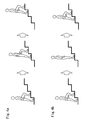
- FIG. 4A is a diagram showing an example of the stair climbing operation with one step and one step
- FIG. 4B is a diagram showing an example of the stair climbing operation with two steps and one step.
- FIG. 6A is a diagram showing the support leg phase of the step-down operation
- FIG. 6B is a diagram showing the support leg phase of the step-down operation
- FIGS. 7a to 7c are diagrams showing examples of task switching situations between a flat ground walking task and a stair climbing task. It is a figure which shows each parameter obtained by a healthy person's walk on a flat ground. It is a figure which shows the path
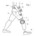
- FIG. 1 is an external view of a wearable motion assisting device (hereinafter referred to as “motion assisting device”) according to an embodiment of the present invention.
- disconnected is demonstrated as an example.
- the motion assisting device includes a socket 10, a thigh frame 12, a knee joint portion 14, a crus frame 16, and a foot portion 18.
- the socket 10 is formed with an insertion recess that matches the shape of the right thigh on the inside, and is molded, for example, from a resin or the like. For example, by fitting the cut end of the right thigh of the wearer P into the insertion recess of the socket 10, and removing the air between the cut end and the socket 10 to apply negative pressure to the socket 10. Worn by the person P.
- the thigh frame 12 is provided with an absolute angle sensor that detects an angle formed with the vertical direction of the hip joint. This absolute angle sensor calculates an absolute angle (hip joint angle) with the vertical direction of the hip joint (thigh) using an acceleration sensor for low frequency operation and a gyro for high frequency operation.
- the knee joint part 14 functions as the right knee joint of the wearer P.
- the other end of the thigh frame 12 is coupled to one side of the knee joint portion 14, and one end of the crus frame 16 is coupled to the other side.
- the knee joint portion 14 rotatably connects the thigh frame 12 and the crus frame 16.
- the knee joint 14 is provided with a drive unit 20.
- the drive part 20 consists of an electric motor, and drives the knee joint part 14 directly. Thereby, the knee joint can be actively bent and extended.
- the drive unit 20 is provided with an angle sensor (not shown) for detecting the angle (flexion angle) of the knee joint. This angle sensor is, for example, a potentiometer.
- the foot 18 is an energy storage type foot that can use the energy stored at the time of the support leg for kicking out mainly by the elastic force of the carbon plate.
- the foot 18 is provided with an insole-like floor reaction force sensor (not shown).
- the floor reaction force sensor calculates the reaction force from the floor to the wearer P by measuring the pressure between the wearer P and the floor.
- the floor reaction force sensor is also provided on the healthy leg side (left leg side in the example shown in FIG. 1).
- a biological signal detection sensor (not shown) for detecting a bioelectric potential (biological signal) in the right leg thigh is attached to the front and back skin surfaces of the right leg thigh of the wearer P.
- a waist belt 30 is attached to the waist of the wearer P, and on the back side of the waist belt 30, a control unit 40 that acquires detection results from each sensor and controls the drive unit 20, and a control unit 40, A battery 50 for supplying power to each sensor is mounted.
- FIG. 2 is a block diagram showing a control system of the motion assist device.
- the motion assisting device includes biopotential signal detection means 102, joint angle detection means 104, floor reaction force detection means 106, control device 110, drive signal generation means 120, and drive unit 20.
- the biopotential signal detection means 102 is composed of the above-described biosignal detection sensor.
- the joint angle detection unit 104 includes the absolute angle sensor described above or an angle sensor provided in the drive unit 20.
- the floor reaction force detection means 106 includes the floor reaction force sensor described above.
- the control device 110 includes an optional control unit 112, an autonomous control unit 114, a data storage unit 116, and a command signal synthesis unit 118, and corresponds to the control unit 40 in FIG.
- the optional control means 112 performs signal processing including filter processing (smoothing processing) and amplification on the biopotential signal detected by the biopotential signal detection means 102. And the voluntary control means 112 produces
- the data storage means 116 stores a reference parameter database for identifying the task phase of the wearer P and information on a method for controlling the drive torque of the drive unit 20 according to the identified phase.
- a task is a classification of human main motion patterns.
- a phase is a series of minimum operation units constituting each task. Analyzing general human movements shows that typical movement patterns such as the angle of each joint and movement of the center of gravity in each phase are determined. Therefore, for each phase constituting a large number of basic operations (tasks) of humans, typical joint angle displacements, centroid movement states, and the like are obtained empirically and stored in a reference parameter database. The task and phase will be described later.
- the autonomous control means 114 includes parameters indicating the operation state of the wearer P such as the joint angle detected by the joint angle detection means 104 and the floor reaction force detected by the floor reaction force detection means 106, and data storage means 116. The stored reference parameters are compared with each other, and the task and phase of the operation of the wearer P are specified. The autonomous control means 114 generates an autonomous command signal for causing the drive unit 20 to generate power according to the identified phase.
- the command signal synthesis unit 118 synthesizes the arbitrary command signal generated by the optional control unit 112 and the autonomous command signal generated by the autonomous control unit 114, and outputs the synthesized command signal to the drive signal generation unit 120.
- the composite ratio (hybrid ratio) of the voluntary command signal and the autonomous command signal may be set in advance for each task phase and stored in the data storage means 116. This hybrid ratio is set in advance so that the operation of the wearer P can be assisted without a sense of incongruity for each phase of each task.
- the command signal synthesizing unit 118 synthesizes the voluntary command signal and the autonomous command signal so as to obtain a hybrid ratio corresponding to the specified phase, and generates a synthesized command signal.
- the combined command signal has a waveform that causes the drive unit 20 to generate combined power of power by optional control that changes from the start to the end of operation and power by autonomous control for each phase.
- the drive signal generation means 120 drives the drive unit 20 by generating a drive signal (drive current) corresponding to the combined command signal and supplying it to the drive unit 20.
- the drive unit 20 applies an assist force (power) according to the drive signal to the wearer P.
- the voluntary control means 112 does not generate an optional command signal, but is generated by the autonomous control means 114. Power based on the autonomous command signal may be generated in the drive unit 20.
- Examples of tasks for classifying the movement of the wearer P include a flat ground walking operation, a stair climbing operation, and a stair descending operation.
- FIG. 3 shows a series of flows of a person walking on a flat ground.
- a person's walking state is roughly divided into a swing leg period and a support leg period.
- the free leg period is a period of movement in which the foot leaves the ground and swings out the lower leg.
- the support leg period is a period in which the foot touches the ground and supports its own weight.
- the flat ground walking task is composed of a free leg phase and a support leg phase.
- the knee joint bends immediately after the transition from the support leg phase to the free leg phase.
- the hip joint bends for the next step, and the knee joint begins to extend with a delay from the middle of the stance.
- the lower leg interlocks and extends with a delay in the movement of the thigh.
- the command torque to the drive unit 20 is calculated from the hip joint angular velocity obtained from the absolute angle sensor so that the lower leg moves in synchronization with the movement of the thigh in the swing leg phase.
- the calculation formula of the command torque in the free leg phase is as shown in the following formula (1).
- the delay time T is about 100 ms, for example. Further, the gains K fl and K ex are different values.
- the torque control in the swing leg phase constitutes a feedforward control system. For this reason, even if the transition to the free leg phase of the flat ground walking task is made by mistake, the knee joint is not driven unless the thigh is flexed and extended arbitrarily.
- the torque control in the support leg phase is the same as the torque control in the stairs descending operation described later.
- position control is performed with the fully extended position as the target angle in the support leg phase.
- the torque control in the support leg phase was the same as the torque control in the step down operation described later.
- the stair climbing operation in the present embodiment is a climbing operation step by step.
- FIG. 4a shows an example of a stair climbing operation in a step-over-step
- FIG. 4b shows an example of a stair climbing operation in a step-by-step.
- One step and one step is a general lifting method when a healthy person goes up and down the stairs, and it goes up and down with alternate legs step by step.
- Two steps and one step is a method of raising and lowering when there is an obstacle or damage to the lower limbs.
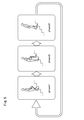
- the stair climbing task is composed of three phases: a flexion phase (phase 1), a sole horizontal phase (phase 2), and a body push-up phase (phase 3).
- a target trajectory is generated for each phase, and torque control is performed so as to follow the trajectory.
- the minimum jerk model (Minimum Jerk Trajectory), which is considered to be close to human leaching motion, is used to reproduce human smooth motion.
- the knee joint In the flexion phase (phase 1), the knee joint is bent so that the toes of the foot 18 do not trip over the steps of the stairs.
- the staircase kick-up dimension is determined to be 230 mm or less. Therefore, the reverse kinematics is determined from the link length of the thigh and lower leg of the wearer P so that the step-up dimension can exceed the step of 230 mm Is used to calculate the knee joint target angle for the first step.
- the wearer P bends the hip joint in accordance with the timing at which the knee joint bends so that the toe of the foot 18 does not hit the step in the extension operation in the sole horizontal phase (phase 2).
- transition to the sole horizontal phase (phase 2) may be performed when the bioelectric potential signal strength on the extension side detected by the biological signal detection sensor becomes a predetermined value or more.
- phase 2 the knee joint is controlled so that the sole is horizontal with the ground. From the angle of the thigh obtained from the absolute angle sensor, the knee joint target angle is calculated so that the sole is horizontal, and the torque is controlled so that the knee joint flexion angle becomes the target angle.
- the wearer P puts weight on the step with the foot 18 on the movement assisting device side. When weight is applied at a certain rate, the body transitions to the body push-up phase (phase 3).
- phase 3 when the motion assist device becomes the support leg, torque control is performed with the fully extended position as the target angle. After the knee joint is fully extended, when the foot 18 of the motion assisting device is left, the transition is made to the flexion phase (phase 1).
- the stairs descending operation is also a step-by-step descending operation, similar to the above-described stairs climbing operation.
- the step-down operation is composed of a support leg phase (FIG. 6a) and a free leg phase (FIG. 6b).
- the knee joint In the support leg phase shown in FIG. 6a, the knee joint is slowly bent while supporting its own weight. At this time, the knee joint is bent by the external force F, and a torque ⁇ k that supports its own weight in the extension direction opposite to the external force F is output.
- the support leg phase and the free leg phase are common in that torque is output in the extending direction. Therefore, the knee joint is controlled using the complete extension angle as a target angle. Since a large torque is required in the support leg phase and a small torque is required in the swing leg phase, the gain is set separately on the flexion side and the extension side, and the gain is switched according to the current rotation direction of the knee joint.
- the calculation formula of the command torque in the step down operation is as shown in the following formula (4).
- the method for calculating the command torque is the same as the method for calculating the command torque in the support leg phase of the flat ground walking motion.
- the knee joint is slowly bent by setting the gains K P_ft and K D_ft at the time of bending large and leaving the weight to the motion assisting device in the support leg phase.
- the gain K P_ex during extension by setting the K D_ex, knee joint smoothly extended in the free leg phase. By repeating this support leg phase and swing leg phase, you can go down the stairs.
- FIGS. 7a to 7c show examples of task switching situations between the above-described flat ground walking task and stair climbing task.
- FIG. 7 a shows a case where the climbing from the flat leg task to the stair climbing task starts to climb from the leg on the healthy leg side.
- FIG. 7 b shows a case where walking is started from the leg on the motion assisting device side (prosthetic leg side) when transitioning from the stair climbing task to the flat ground walking task.
- FIG. 7c shows a case in which walking is started from the leg on the healthy leg side when transitioning from the stair climbing task to the flat ground walking task, contrary to FIG. 7b.
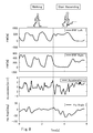
- a healthy person wearing a movement assist device using a simulated thigh socket on the right leg walks on a flat ground in a flat ground walking task, and moves up from a healthy leg to a step with a lift-up dimension of 180 mm.
- An example of the data thus obtained is shown in FIG.
- the horizontal axis of the graph is time [s]
- the vertical axis is the foot side floor reaction force (FRF Left), the motion assist side floor reaction force (FRF Right), and the vertical acceleration (Acceleration Z) obtained from the absolute angle sensor. , Hip Angle.
- the task switching condition is that the floor reaction force on the healthy foot side is large (becomes a predetermined value or more) and the leg on the movement assisting device side is moving in the bending direction.
- the task switching condition is that the floor reaction force on the side of the motion assisting device is greatly generated (becomes a predetermined value or more) and the leg on the side of the motion assisting device is moving in the extending direction.
- the angular velocity is calculated from the absolute thigh angle detected by the absolute angle sensor in the free leg phase of the flat ground walking task, and the angular velocity is used to interlock with the hip joint. To bend the knee joint. For this reason, walking on a flat ground equivalent to that of a healthy person can be realized.
- the knee joint target angle for the first step is calculated using the knee joint, and the knee joint is bent using the knee joint target angle.
- the knee joint flexion angle reaches the target angle, or when the bioelectric potential signal on the extension side exceeds the predetermined value, the knee phase transitions from the flexion phase to the sole horizontal phase, and from the thigh angle obtained from the absolute angle sensor
- the knee joint target angle is calculated so that the sole of the foot is horizontal, and the knee joint is bent using the knee joint target angle.
- the foot horizontal phase shifts to the body push-up phase, and the knee joint is bent with the complete extension position as the target angle. Then, when the foot 18 of the motion assisting device leaves the floor, the body push-up phase transitions to the bending phase.
- the knee joint is flexed slowly in the support leg phase and the knee joint is smooth in the free leg phase. It is possible to extend the stairs and step down one step at a time.
- switching between the flat ground walking task and the stair climbing task is performed based on the floor reaction force and hip joint angle, etc., and the same torque control is performed in the support leg phase of the stair down task and the flat ground walking task, and the support leg phase of the walking task. Because it is possible to go down the stairs as it is, without using a special device such as a switch, it is possible to seamlessly switch between the three tasks of walking on the ground, climbing the stairs, and going down the stairs according to the movement of the wearer P. be able to. Therefore, walking equivalent to that of a healthy person can be realized.
- the wearable movement assist device may be a prosthetic limb wearing type attached to a commercially available prosthetic limb (prosthetic leg).
- a commercially available prosthetic leg component includes a thigh frame, a crus frame, a foot, and a joint that rotatably connects the thigh frame and the crus frame.
- the drive unit 20 is connected to the thigh frame and the crus frame, and is attached so that the rotation axis coincides with the rotation center of the joint and is coaxial.
- the artificial limb-mounted motion assisting device includes an external drive unit 20, a floor reaction force sensor, a biological signal detection sensor, an absolute angle sensor, and a control unit 40.
- the subject tested each of the flat ground walking motion, the stair climbing operation, and the stair climbing motion with and without the motion assist device.
- the subject walked at a comfortable speed (Comfortable speed) when the movement assist device was not worn, and walked at a comfortable speed and a maximum effort speed (Maximum speed) when worn. Under these three conditions, the tests described below were tried five times and compared.
- a 14-step staircase with a kick height of 180 mm, a width of 1400 mm, a depth of 280 mm was used.
- the stair climbing operation resulted in a slower speed than that of the healthy person in both the comfortable speed and the maximum effort speed of the motion assist device.
- the maximum effort speed of the motion assisting device was 61% of the comfortable walking speed of a healthy person. From the above, it is considered that the leg amputee can climb the stairs at a speed of about 60% of that of a healthy person by using the motion assist device.
- the speed of the stairs climbing movement is slower than that of a normal person because it is necessary to draw a larger orbit than that of a normal person in order to generate a trajectory in which the ankle is fixed and the toes do not hit a step in the movement assist device. it is conceivable that.
- Fig. 12 shows that the comfortable speed of the motion assisting device was the same as the comfortable speed of the healthy person in the stairs down operation.
- the maximum effort speed of the motion assist device was 1.3 times faster than the comfortable speed of the healthy person. From the above, it is considered that the leg amputee can get down the stairs at a speed equivalent to that of a healthy person by using the motion assist device.
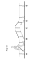
- Task switching test One healthy person wearing a motion assisting device walked along the path that required the flat ground walking operation and the stair climbing operation shown in FIG. 13, and confirmed task switching according to the situation.
- the steps to be used have 5 steps and 3 steps on both sides, and the 5 step-up height is 120 mm, and the 3 step-up height is 200 mm. Walk from point A in FIG. 13, go up the stairs in section BC, go down the stairs in section CD, and walk to point E. Then, return the same route to point A.
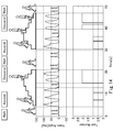
- FIG. 14 shows the result of this task switching test.
- FIG. 14 shows the state of motion, the knee joint angle of the motion assist device, and the task number.
- the task number 0 indicates a flat ground walking task
- 1 indicates a stair climbing task
- 2 indicates a stair descending task.
- the motion assist device uses only the floor reaction force as information on the healthy leg side, it can be applied not only to patients with one thigh amputation but also to the study cooperator for both leg amputation.
- Biopotential measurement test A biopotential signal of the knee joint of the right leg necessary for controlling the operation assisting device was measured.
- the test cooperator was instructed to apply a force to flex and extend the knee joint, and an electrode for bioelectric potential measurement was attached to the skin surface of the swelled muscle.
- the bioelectric potential was measured by the motion assisting device, and at the same time, voluntary control based on the following formula (5) was performed as feedback to the test cooperator.
- ⁇ BES is a command torque by voluntary control
- E fl and E ex are bioelectric potential signal strengths associated with flexion and extension
- K fl and K ex are gains for converting the bioelectric potential signal of flexion and extension into knee joint command torque, respectively.
- test cooperator is instructed to bend and extend the knee joint, and whether the knee joint of the motion assist device bends and extends as instructed by the waveform change of the bioelectric potential signal obtained at that time and optional control It was confirmed.
- KneegleAngle represents the change in the angle of the knee joint of the movement assist device
- BES Extension and BES Flexion represent the strength of the bioelectric potential signal of extension and bending, respectively.
- the 100% MVC method was applied to the measurement result of the biopotential signal.
- the biopotential signal corresponding to the instruction of bending extension could be acquired. From FIG. 15, it was confirmed that the knee joint of the motion assisting device can be alternately bent and extended by voluntary control, and the bioelectric potential signal can be acquired independently by bending and extension without simultaneous contraction. In addition, we received comments from the test cooperators that they can move like their legs and that their legs have returned.
- test cooperator was instructed to walk at a comfortable speed with both the motion assist device and the prosthetic leg that he normally uses.
- the test was conducted after sufficient practice and adjustment of control parameters.
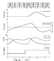
- FIG. 16 shows the knee joint angle, hip joint angle, floor reaction force of both feet, and phase number for one walking cycle when the motion assisting device is used.
- the knee joint was flexed and extended, and it was confirmed that walking was possible while switching the phase between the support leg phase and the swing leg phase.
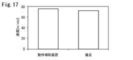
- Fig. 17 shows the speed results calculated from the time required for the 10m walking test of the prosthetic leg normally used with the motion assist device in this test. The result was 39 [s] for the motion assisting device and 38 [s] for the prosthetic leg that was normally used. From FIG. 17, it can be seen that the walking speed is comparable between the motion assist device and the prosthetic leg that is normally used.
- Stair ascent and descent motion test Stair ascending and descending when a leg amputee uses a motion assist device was tested.
- the same staircase as the test by the healthy person described above was used.
- the time required to climb a total of 10 steps from the first step to the eleventh step was measured.
- the stairs descending test the time required to descend a total of 10 steps from the 12th step to the 2nd step was measured.
- One handrail can be used.
- the stairs were raised and lowered by two steps and one step because the method of raising and lowering during normal times was two steps and one step.
- FIG. 18 shows the knee joint angle, hip joint angle, floor reaction force of both feet, and phase number for one walking cycle when the motion assist device is used in the stair climbing motion test.
- FIG. 19 shows knee joint angles, knee joint angular velocities, hip joint angles, and floor reaction forces of both feet when using the motion assisting device in the stair climbing motion test.
- FIG. 20 shows the speed result of the stair climbing test
- FIG. 21 shows the speed result of the stair climbing test.
- the cadence [steps / min] which is the number of steps raised and lowered per minute, was calculated from the measured time and the number of steps taken up and down.
- the motion assist device was able to descend faster than the normal prosthetic leg. This is probably because the gait, which was a two-step gait for the prosthetic leg that we normally use, was changed to a one-step gait for the movement assist device. Furthermore, it solves the problem that the range of motion of the ankle joint is limited by placing the foot of the sole of the sole against the corner of the step and rotating around the corner of the step to play the role of the ankle joint.
- Task switching test A leg amputee wearing a motion assisting device walks on a route that requires a flat-ground walking operation and a stair climbing operation as shown in FIG. 13 and confirms task switching according to the situation.
- the steps to be used have 5 steps and 3 steps on both sides, and the 5 step-up height is 120 mm, and the 3 step-up height is 200 mm.
- FIG. 22 shows the result of this task switching test.
- FIG. 22 shows the behavior, the knee joint angle of the motion assisting device, the task number, and the phase number.
- the task number 0 indicates a flat ground walking task, and 1 indicates a stair climbing task. Go down the stairs with both task number and phase number set to 0. This is because, as described in the above embodiment, the same torque control is used in the support leg phase of the flatland walking task and the stairs descending task.
- test cooperators can walk on the test route that requires walking on flat ground and stairs. Furthermore, it was confirmed that the task could be switched according to the situation and a desired operation could be realized without using a special device such as a switch.
- leg amputee can walk alone on a route that requires stairs to be lifted.
- FIG. 1 A schematic diagram inside the building is shown in FIG.
- the walking route starts walking from point A, travels around the building in the order of Walk1, Ascend, Walk2, Descend, Walk3, and measures the time until returning to point A again.
- we walked this route both when using a motion assist device and when using a normal prosthesis.
- the stairs were raised and lowered by two steps and one step because the method of raising and lowering during normal times was two steps and one step.
- the required time was 160 [s] when the motion assist device was used, and 165 [s] when the usual prosthetic leg was used.
- the result using the motion assist device was 5 [s] faster.
- FIG. 24 shows the time required for each route when the motion assist device is used and when a normal prosthesis is used. There was almost no difference between Walk1 and Walk3. Ascend and Walk2 showed slower results with the motion assist device. As for Descend, the operation assisting device was faster.
Landscapes
- Health & Medical Sciences (AREA)
- Engineering & Computer Science (AREA)
- Transplantation (AREA)
- Heart & Thoracic Surgery (AREA)
- Life Sciences & Earth Sciences (AREA)
- Oral & Maxillofacial Surgery (AREA)
- Veterinary Medicine (AREA)
- Biomedical Technology (AREA)
- Public Health (AREA)
- Vascular Medicine (AREA)
- Cardiology (AREA)
- Animal Behavior & Ethology (AREA)
- General Health & Medical Sciences (AREA)
- Robotics (AREA)
- Mechanical Engineering (AREA)
- Orthopedic Medicine & Surgery (AREA)
- Manipulator (AREA)
- Prostheses (AREA)
Abstract
一足一段での階段昇降を可能とするとともに、装着者の動作に合わせてタスクを円滑に切り替えることができる装着式動作補助装置及び義肢装着式動作補助装置を提供する。義肢装着式動作補助装置は、義足の大腿フレームと下腿フレームとの間の膝関節の動作を支援するものであり、前記大腿フレーム及び下腿フレームに連結され、義足に対して動力を付与する駆動部と、鉛直方向に対する股関節角度を検出する絶対角度センサと、膝関節角度を検出する角度センサと、装着者への床反力を検出する床反力センサと、タスクのフェイズの基準パラメータを格納したデータ格納部と、前記股関節角度、前記膝関節角度、及び前記床反力と、前記データ格納部に格納された基準パラメータとを比較することにより、装着者のタスクのフェイズを推定し、このフェイズに応じた動力を前記駆動部に発生させるための自律指令信号を生成する制御部と、を備える。
Description
本発明は、義肢を装着した装着者の動作を補助する義肢装着式動作補助装置及び装着式動作補助装置に関する。
下肢は、日常生活において平地歩行や階段昇降といった移動動作を行うために重要な部位であり、事故等により下肢を失うことは移動能力の低下につながる。下肢切断は、足関節と膝関節の間での切断である下腿切断と、膝関節と股関節の間での切断である大腿切断の2つに大別される。
下腿切断では、膝関節が残存していることから、下腿義足を使用することによって歩行や階段昇降等の動作が可能である。
一方、大腿切断では、失った膝関節を大腿義足で補う必要がある。一般的な大腿義足は、膝継手と呼ばれる義足の膝関節に、バネやダンパの特性をもたせた受動義足である。また、義足の関節を駆動する駆動手段を設け、随意的制御手段により、太腿部から検出される生体信号を用いて装着者の意思に従った動力を駆動手段に発生させたり、装着者の各動作パターンを一連のフェイズ(最小動作単位)からなるタスクとして分類し、自律的制御手段により、膝関節部の回転角や床反力等の物理量を用いて装着者のタスクのフェイズを推定し、このフェイズに応じた動力を駆動手段に発生させたりする装着式動作補助装置が提案されている(例えば特許文献1参照)。
上述した従来の義足は、比較的容易に平地歩行を行うことができた。しかし、健常者と同様の、一足一段での階段昇降動作を行うことが困難であった。また、装着者の意思を読み取ることが出来ないため、平地歩行から階段昇降への切り替えや、階段昇降から平地歩行への切り替えを円滑に行うことができず、健常者と同等の歩行を実現することは困難であった。
本発明は、一足一段での階段昇降を可能とするとともに、平地歩行、階段昇り、及び階段降りの3つのタスクを装着者の動作に合わせて円滑に切り替えることができる義肢装着式動作補助装置及び装着式動作補助装置を提供することを課題とする。
本発明の一態様による義肢装着式動作補助装置は、義足の大腿フレームと下腿フレームとの間の膝関節の動作を支援する義肢装着式動作補助装置であって、前記膝関節の外側に配置され、前記大腿フレーム及び前記下腿フレームに連結され、前記義足に対して動力を付与する駆動部と、鉛直方向に対する股関節角度を検出する絶対角度センサと、前記駆動部に設けられ、膝関節角度を検出する角度センサと、装着者への床反力を検出する床反力センサと、タスクとして分類した装着者の動作パターンを構成する一連の最小動作単位(フェイズ)の各々の基準パラメータを格納したデータ格納部と、前記股関節角度、前記膝関節角度、及び前記床反力と、前記データ格納部に格納された基準パラメータとを比較することにより、前記装着者のタスクのフェイズを推定し、このフェイズに応じた動力を前記駆動部に発生させるための自律指令信号を生成する制御部と、を備える。
本発明の一態様による義肢装着式動作補助装置においては、前記制御部は、階段昇りタスクの屈曲フェイズにおいて、前記義足のつま先が所定の高さの段差を超えられるように、前記大腿フレーム及び前記下腿フレームの長さから逆運動学を用いて膝関節目標角度を算出し、該膝関節目標角度と前記角度センサにより検出される膝関節角度との偏差に基づいて前記自律指令信号を生成することが好ましい。
本発明の一態様による義肢装着式動作補助装置においては、前記制御部は、階段昇りタスクの足裏水平フェイズにおいて、前記股関節角度を用いて足裏が水平になる膝関節目標角度を算出し、該膝関節目標角度と前記角度センサにより検出される膝関節角度との偏差に基づいて前記自律指令信号を生成することが好ましい。
本発明の一態様による義肢装着式動作補助装置においては、前記制御部は、前記角度センサにより検出される膝関節角度が前記膝関節目標角度に達すると、屈曲フェイズから足裏水平フェイズに遷移することが好ましい。
本発明の一態様による義肢装着式動作補助装置においては、前記制御部は、階段降りタスク又は平地歩行タスクの支持脚フェイズにおいて、完全伸展角度と前記角度センサにより検出される膝関節角度との偏差にゲインを掛け合わせた値を用いて前記自律指令信号を生成し、屈曲時のゲインは、伸展時のゲインよりも大きいことが好ましい。
本発明の一態様による義肢装着式動作補助装置においては、前記制御部は、平地歩行タスクの遊脚フェイズにおいて、前記股関節角度から股関節角速度を算出し、所定時間前の股関節角速度にゲインを掛け合わせた値を用いて前記自律指令信号を生成することが好ましい。
本発明の一態様による義肢装着式動作補助装置においては、前記制御部は、前記股関節角度、前記膝関節角度、及び前記床反力に基づいて、平地歩行タスクと階段昇りタスクの切り替えを行うことが好ましい。
本発明の一態様による義肢装着式動作補助装置においては、前記制御部は、健足側床反力、義足側床反力、前記絶対角度センサから得られる鉛直方向加速度、及び前記股関節角度に基づいて、平地歩行タスクから階段昇りタスクへの切り替えを行うことが好ましい。
本発明の一態様による義肢装着式動作補助装置においては、前記制御部は、健足側床反力が所定値以上となり、前記膝関節が屈曲方向に運動している場合、階段昇りタスクから平地歩行タスクへの切り替えを行うことが好ましい。
本発明の一態様による義肢装着式動作補助装置においては、前記制御部は、義足側床反力が所定値以上となり、前記膝関節が伸展方向に運動している場合、階段昇りタスクから平地歩行タスクへの切り替えを行うことが好ましい。
本発明の一態様による義肢装着式動作補助装置においては、前記装着者の大腿部における生体信号を検出する生体信号センサをさらに備え、前記制御部は、階段昇りタスクにおいて、該生体信号センサにより検出される伸展側の生体信号の強度が所定値以上となった場合に、屈曲フェイズから足裏水平フェイズに遷移することが好ましい。
本発明の一態様による義肢装着式動作補助装置においては、前記制御部は、前記生体信号に応じた動力を前記駆動部に発生させるための随意指令信号を生成し、前記随意指令信号及び前記自律指令信号を合成して合成指令信号を生成し、前記駆動部は、前記合成指令信号に基づいて生成された駆動電流により駆動することが好ましい。
本発明の一態様による義肢装着式動作補助装置においては、前記データ格納部は、各タスクのフェイズ毎に設定された前記随意指令信号と前記自律指令信号との合成比を格納し、前記制御部は、推定したフェイズに応じた合成比となるように、前記随意指令信号と前記自律指令信号とを合成して合成指令信号を生成することが好ましい。
本発明の一態様による装着式動作補助装置は、一端が装着者の大腿部に装着されるソケットに連結される大腿フレームと、一側が前記大腿フレームに結合される膝関節部と、一端が前記膝関節部の他側に結合される下腿フレームと、前記下腿フレームの他端に結合される足部と、前記膝関節部に設けられ、駆動力の発生により前記大腿フレーム又は前記下腿フレームを回動させる駆動部、及び膝関節角度を検出する角度センサと、前記大腿フレームに設けられ、鉛直方向に対する股関節角度を検出する絶対角度センサと、前記足部に設けられ、装着者への床反力を検出する床反力センサと、タスクとして分類した装着者の動作パターンを構成する一連の最小動作単位(フェーズ)の各々の基準パラメータを格納したデータ格納部と、前記股関節角度、前記膝関節角度、及び前記床反力と、前記データ格納部に格納された基準パラメータとを比較することにより、前記装着者のタスクのフェイズを推定し、このフェイズに応じた動力を前記駆動部に発生させるための自律指令信号を生成する制御部と、を備える。
本発明によれば、一足一段での階段昇降を可能とするとともに、平地歩行、階段昇り、及び階段降りの3つのタスクを装着者の動作に合わせて円滑に切り替え、健常者と同等の歩行を実現することができる。
以下、本発明の実施の形態を図面に基づいて説明する。
図1は本発明の実施形態に係る装着式動作補助装置(以下、「動作補助装置」と称する)の外観図である。なお、図1では、装着者Pの切断された右脚の大腿部に装着される動作補助装置を一例として説明する。動作補助装置は、ソケット10、大腿フレーム12、膝関節部14、下腿フレーム16、及び足部18を備えている。
ソケット10は、内側に右大腿部の形状に合わせた挿入凹部が形成されており、例えば樹脂等により成型される。例えば、ソケット10の挿入凹部に装着者Pの切断された右大腿部の断端を嵌合し、断端とソケット10との間の空気を抜きソケット10に陰圧をかけることで、装着者Pに装着される。
大腿フレーム12の一端はアタッチメント(図示せず)を介してソケット10に結合しており、他端は膝関節部14に結合している。大腿フレーム12には、股関節の鉛直方向とのなす角度を検出する絶対角度センサが設けられている。この絶対角度センサは、低周波数の動作では加速度センサ、高周波数の動作ではジャイロを用いて、股関節(大腿)の鉛直方向とのなす絶対角(股関節角度)を算出する。
膝関節部14は、装着者Pの右膝関節として機能する。膝関節部14の一側には大腿フレーム12の他端が結合されており、他側には下腿フレーム16の一端が結合されている。膝関節部14は大腿フレーム12及び下腿フレーム16を回動可能に連結している。また、膝関節部14には駆動部20が設けられている。駆動部20は電動モータからなり、膝関節部14を直接駆動する。これにより、膝関節を能動的に屈曲伸展させることができる。駆動部20には、膝関節の角度(屈曲角度)を検出する角度センサ(図示せず)が設けられている。この角度センサは例えばポテンショメータである。
下腿フレーム16の他端は足部18に結合されている。足部18には、主にカーボンのプレートによる弾性力によって支持脚時に蓄えられたエネルギーを蹴り出しに利用することが可能なエネルギー蓄積型足部が用いられる。足部18には靴の中敷き状の床反力センサ(図示せず)が設けられている。床反力センサは、装着者Pと床との圧力を計測することで、床から装着者Pへの反力を求める。この床反力センサは、健足側(図1に示す例では左足側)にも設けられる。
また、装着者Pの右脚大腿部の前後皮膚表面には、右脚大腿部における生体電位(生体信号)を検出する生体信号検出センサ(図示せず)が貼り付けられる。
装着者Pの腰には腰ベルト30が装着されており、この腰ベルト30の後側には、各センサから検出結果を取得して駆動部20を制御する制御部40、及び制御部40や各センサに電力を供給するバッテリ50が搭載されている。
図2は、動作補助装置の制御系を示すブロック図である。動作補助装置は、生体電位信号検出手段102、関節角度検出手段104、床反力検出手段106、制御装置110、駆動信号生成手段120、及び駆動部20を備える。
生体電位信号検出手段102は、上述した生体信号検出センサからなる。関節角度検出手段104は、上述した絶対角度センサや駆動部20に設けられた角度センサからなる。床反力検出手段106は、上述した床反力センサからなる。
制御装置110は、随意制御手段112、自律制御手段114、データ格納手段116、及び指令信号合成手段118を有し、図1の制御部40に対応する。
随意制御手段112は、生体電位信号検出手段102により検出された生体電位信号に対して、フィルタ処理(スムージング処理)及び増幅を含む信号処理を行う。そして、随意制御手段112は、信号処理を施した生体電位信号を用いて、装着者Pの意思に従った動力を駆動部20に発生させるための随意指令信号を生成する。
データ格納手段116は、装着者Pのタスクのフェイズを特定するための基準パラメータデータベースと、特定されたフェイズに応じて駆動部20の駆動トルクを制御する方法についての情報とを格納する。タスクとは、人間の主要な動作パターンを分類したものである。フェイズとは、各タスクを構成する一連の最小動作単位である。人間の一般的な動作を分析すると、各フェイズにおける各関節の角度や重心の移動等の典型的な動作パターンが決まっていることが分かる。そこで、人間の多数の基本動作(タスク)を構成する各フェイズについて、典型的な関節角度の変位や重心移動の状態等を経験的に求め、それらを基準パラメータデータベースに格納しておく。タスク及びフェイズについては後述する。
自律制御手段114は、関節角度検出手段104により検出された関節角度及び床反力検出手段106により検出された床反力等の装着者Pの動作の状態をあらわすパラメータと、データ格納手段116に格納された基準パラメータとを比較して、装着者Pの動作のタスク及びフェイズを特定する。自律制御手段114は、特定したフェイズに応じた動力を駆動部20に発生させるための自律指令信号を生成する。
指令信号合成手段118は、随意制御手段112により生成された随意指令信号と、自律制御手段114により生成された自律指令信号とを合成し、合成指令信号を駆動信号生成手段120へ出力する。
随意指令信号と自律指令信号との合成比(ハイブリッド比)を各タスクのフェイズ毎に予め設定してデータ格納手段116に格納しておいてもよい。このハイブリッド比は、各タスクのフェイズ毎に、装着者Pの動作を違和感なくアシストできるように予め設定される。指令信号合成手段118は、特定されたフェイズに応じたハイブリッド比となるように随意指令信号と自律指令信号とを合成し、合成指令信号を生成する。
合成指令信号は、動作の開始から終了まで変化する随意的制御による動力と、フェイズ毎の自律的制御による動力とを合成した動力を駆動部20に発生させる波形を有する。
駆動信号生成手段120は、合成指令信号に応じた駆動信号(駆動電流)を生成し、駆動部20に供給することにより、駆動部20を駆動する。駆動部20は、駆動信号に応じたアシスト力(動力)を装着者Pに付与する。
装着者Pの皮膚が汗で濡れる等により生体電位信号検出手段102が生体電位信号を検出できない場合には、随意制御手段112による随意指令信号の生成は行わず、自律制御手段114により生成された自律指令信号に基づく動力を駆動部20に発生させてもよい。
次に、タスク及びフェイズと、自律制御手段114による駆動部20への指令トルクの制御方法について説明する。装着者Pの動作を分類するタスクとしては、例えば、平地歩行動作、階段昇り動作、階段降り動作などがある。
[平地歩行動作]
図3に人の平地歩行の一連の流れを示す。人の歩行状態は遊脚期と支持脚期の2つに大別される。遊脚期は足が地面から離れ下腿を振り出す動作の期間である。支持脚期は足が地面に接地し自重を支えている期間である。平地歩行タスクは、遊脚フェイズと支持脚フェイズにより構成される。
図3に人の平地歩行の一連の流れを示す。人の歩行状態は遊脚期と支持脚期の2つに大別される。遊脚期は足が地面から離れ下腿を振り出す動作の期間である。支持脚期は足が地面に接地し自重を支えている期間である。平地歩行タスクは、遊脚フェイズと支持脚フェイズにより構成される。
遊脚フェイズでは、支持脚フェイズから遊脚フェイズへ遷移した直後に膝関節が屈曲する。股関節は次の1歩のために屈曲し、立脚中期から膝関節は遅れて伸展を始める。このように遊脚フェイズでは大腿の動きに遅れて下腿が連動して屈曲伸展する。本実施形態では、遊脚フェイズにおいて大腿の動きに遅れて下腿が連動して動くように、絶対角度センサから得られる股関節角速度から駆動部20への指令トルクを算出する。遊脚フェイズにおける指令トルクの算出式は以下の数式(1)のようになる。

遅延時間Tは例えば100ms程度である。また、ゲインKflとKexとは異なる値である。
遊脚フェイズにおけるトルク制御は、フィードフォワードの制御系を構成している。そのため、誤って平地歩行タスクの遊脚フェイズへ遷移しても、大腿部を随意的に屈曲伸展しない限り膝関節は駆動しない。
支持脚フェイズにおけるトルク制御は、後述する階段降り動作でのトルク制御と同じである。つまずきなどによる膝折れを防止するため、支持脚フェイズでは、完全伸展位を目標角度とした位置制御を行う。義足が遊脚フェイズから支持脚フェイズへ遷移する際に完全伸展位で着床することで、ハードウェアの構造的に支持脚期での膝折れを防止できる。支持脚フェイズにおけるトルク制御は、後述する階段降り動作でのトルク制御と同一のものとした。平地歩行動作の支持脚フェイズのまま階段を降りることで、タスクの切り替えが不要となり、プログラムを単純化できる。
このような遊脚フェイズ、支持脚フェイズのトルク制御を繰り返すことで、平地歩行動作が実現される。
[階段昇り動作]
次に、階段昇り動作でのトルク制御について説明する。本実施形態における階段昇り動作は、一足一段での昇り動作である。図4aに一足一段(Step-Over-Step)での階段昇り動作の例を示し、図4bに二足一段(Step-By-Step)での階段昇り動作の例を示す。一足一段は、健常者が階段昇降を行う際の一般的な昇降方法であり、一段ずつ交互の脚で昇降する。二足一段は、下肢に障害や損傷のある場合の昇降方法であり、両足を同じ段へ配置した後、片脚で昇降動作を行う。
次に、階段昇り動作でのトルク制御について説明する。本実施形態における階段昇り動作は、一足一段での昇り動作である。図4aに一足一段(Step-Over-Step)での階段昇り動作の例を示し、図4bに二足一段(Step-By-Step)での階段昇り動作の例を示す。一足一段は、健常者が階段昇降を行う際の一般的な昇降方法であり、一段ずつ交互の脚で昇降する。二足一段は、下肢に障害や損傷のある場合の昇降方法であり、両足を同じ段へ配置した後、片脚で昇降動作を行う。
階段昇りタスクは、図5に示すように、屈曲フェイズ(phase1)、足裏水平フェイズ(phase2)、身体押上フェイズ(phase3)の3つのフェイズから構成される。それぞれのフェイズ毎に目的の軌道を生成し、その軌道を追従するようにトルク制御を行う。軌道生成には、人のリーチング動作に近いとされる躍度最小モデル(Minimum Jerk Trajectory)を使用し、人の滑らかな運動を再現する。
屈曲フェイズ(phase1)では、足部18のつま先が階段の段差に当たりつまずかないように膝関節を屈曲させる。建築基準法において、階段の蹴上寸法は230mm以下と定められているため、蹴上寸法が230mmの段差を超えられるように装着者Pの大腿部、下腿部のリンク長から逆運動学を用いて一歩目の膝関節目標角度を算出する。装着者Pは、足部18のつま先が足裏水平フェイズ(phase2)での伸展動作で段差に当たらないように、膝関節が屈曲するタイミングに合わせて股関節を屈曲させる。膝関節屈曲角度が目標角度になると、足裏水平フェイズ(phase2)に遷移する。あるいはまた、生体信号検出センサにより検出される伸展側の生体電位信号強度が所定値以上となった場合に足裏水平フェイズ(phase2)に遷移してもよい。
足裏水平フェイズ(phase2)では、足裏が地面と水平となるように膝関節を制御する。絶対角度センサから得られる大腿部の角度から、足裏が水平になるように膝関節目標角度を算出し、膝関節屈曲角度が目標角度となるようにトルクを制御する。足裏水平フェイズ(phase2)による伸展動作が終了した後、装着者Pは動作補助装置側の足部18で段差に体重を乗せる。体重を一定の割合でかけると、身体押上フェイズ(phase3)に遷移する。
身体押上フェイズ(phase3)では、動作補助装置が支持脚になると、完全伸展位を目標角度としてトルク制御を行う。膝関節が完全伸展した後、動作補助装置の足部18を離床させると、屈曲フェイズ(phase1)に遷移する。
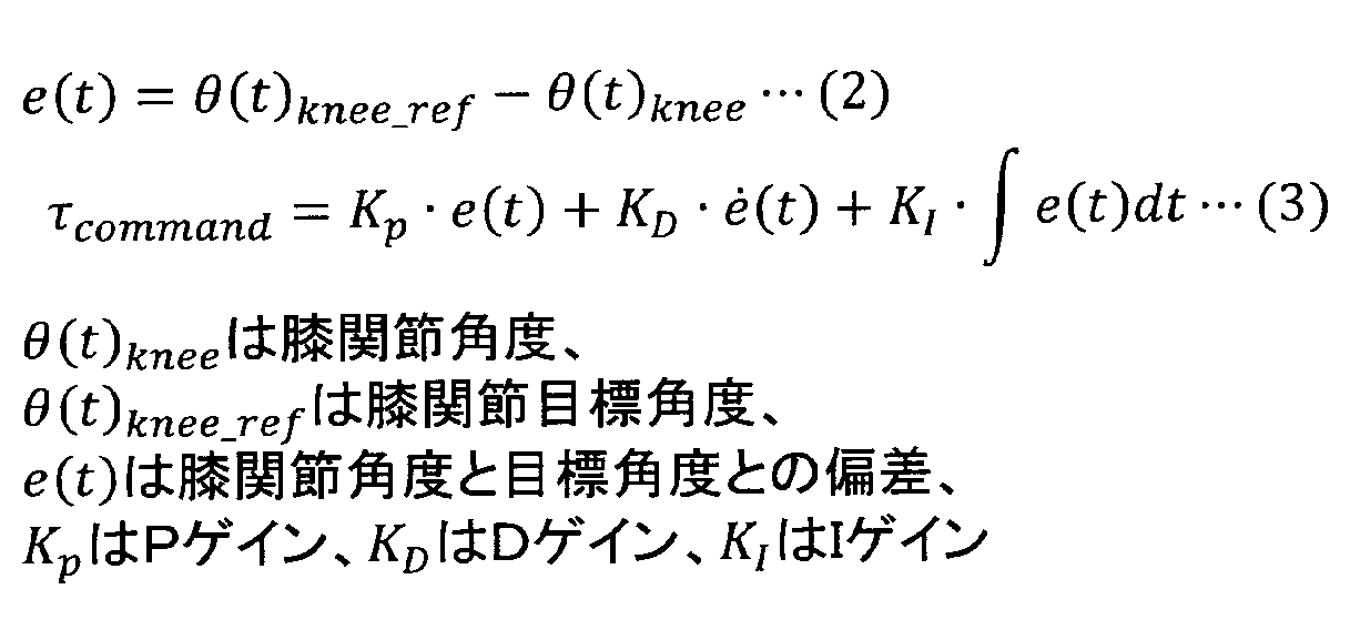
屈曲フェイズ(phase1)、足裏水平フェイズ(phase2)、身体押上フェイズ(phase3)の3つのフェイズを繰り返すことによって、階段を昇ることができる。各フェイズのいずれもPID制御によって制御器を構成し、PIDゲインは試行錯誤的に決定する。階段昇り動作における指令トルクの算出式は以下の数式(2)、(3)のようになる。
[階段降り動作]
次に、階段降り動作でのトルク制御について説明する。なお、階段降り動作についても、上述の階段昇り動作と同様に、一足一段での降り動作である。図6a,6bに示すように、階段降り動作は、支持脚フェイズ(図6a)と遊脚フェイズ(図6b)により構成される。
次に、階段降り動作でのトルク制御について説明する。なお、階段降り動作についても、上述の階段昇り動作と同様に、一足一段での降り動作である。図6a,6bに示すように、階段降り動作は、支持脚フェイズ(図6a)と遊脚フェイズ(図6b)により構成される。
図6aに示す支持脚フェイズでは、自重を支えながらゆっくり膝関節を屈曲させる。このとき、外力Fによって膝関節は屈曲し、外力Fとは反対の伸展方向に自重を支えるトルクτkが出力される.
図6bに示す遊脚フェイズでは、外力Fによる影響がないため、膝関節を滑らかに伸展させるために、支持脚フェイズと比較して小さいトルクτkを伸展方向に出力する。
支持脚フェイズ、遊脚フェイズ共に伸展方向にトルクを出力している点で共通している。そのため、完全伸展角度を目標角度として膝関節の制御を行う。支持脚フェイズでは大きいトルクを必要とし、遊脚フェイズでは必要となるトルクが小さいため、屈曲側と伸展側とでゲインを別々に設定し、現在の膝関節の回転方向に応じてゲインを切り換える。階段降り動作における指令トルクの算出式は以下の数式(4)のようになる。なお、この指令トルクの算出方法は、平地歩行動作の支持脚フェイズにおける指令トルクの算出方法と同じである。
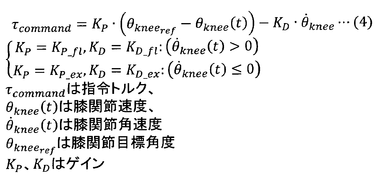
屈曲時のゲインKP_ft、KD_ftを大きく設定し、支持脚フェイズにおいて動作補助装置に体重を預けることで、膝関節がゆっくり屈曲する。また、伸展時のゲインKP_ex、KD_exを小さく設定することで、遊脚フェイズにおいて膝関節が滑らかに伸展する。この支持脚フェイズと遊脚フェイズを繰り返すことで、階段を降りることができる。
[タスクの切り替え]
図7a~7cは、上述した平地歩行タスクと階段昇りタスクとの間でのタスク切り替え状況の例を示す。図7aは、平地歩行タスクから階段昇りタスクへ健足側の脚から昇り始める場合を示す。図7bは、階段昇りタスクから平地歩行タスクへ遷移する際に、動作補助装置側(義足側)の脚から歩行を開始する場合を示す。図7cは、図7bとは逆に、階段昇りタスクから平地歩行タスクへ遷移する際に、健足側の脚から歩行を開始する場合を示す。
図7a~7cは、上述した平地歩行タスクと階段昇りタスクとの間でのタスク切り替え状況の例を示す。図7aは、平地歩行タスクから階段昇りタスクへ健足側の脚から昇り始める場合を示す。図7bは、階段昇りタスクから平地歩行タスクへ遷移する際に、動作補助装置側(義足側)の脚から歩行を開始する場合を示す。図7cは、図7bとは逆に、階段昇りタスクから平地歩行タスクへ遷移する際に、健足側の脚から歩行を開始する場合を示す。
図7aの場合では、事前に健常者による予備実験を行い、その結果からタスク切り替え条件を決定する。
例えば、予備実験では、右脚に模擬大腿ソケットを使用して動作補助装置を装着した健常者1名が平地歩行タスクで平地歩行を行い、蹴上寸法180mmの段差に健足側から昇る動作を行う。これにより得られるデータの一例を図8に示す。グラフの横軸は時間[s]、縦軸はそれぞれ健足側床反力(FRF Left)、動作補助装置側床反力(FRF Right)、絶対角度センサから得られる鉛直方向加速度(Acceleration Z)、股関節角度(Hip Angle)である。
健足側から階段を昇ることにより、健足側が支持脚、動作補助装置側が遊脚となり、FRF Leftが増大し、FRF Rightが減少する。さらに、健足側の脚で段差を一段昇ることによる鉛直方向の加速度が発生することによってAcceleration Zが瞬間的に増大する。さらに、前方に段差があることから動作補助装置側の股関節は鉛直方向からの角度に対して下を向いていることがHip Angleからわかる。
以上の特徴を考慮して各パラメータに閾値を設定し、これらの条件を満たした際に歩行タスクから階段昇りタスクへ切り替える。
人の歩き始めでは、歩き始める脚と反対側の後脚つま先に大きな床反力が発生する。そのため、図7bの場合、健足側の床反力が大きく発生し(所定値以上となり)、動作補助装置側の脚が屈曲方向に運動していることをタスクの切り替え条件とする。また、図7cの場合、動作補助装置側の床反力が大きく発生し(所定値以上となり)、動作補助装置側の脚が伸展方向に運動していることをタスクの切り替え条件とする。
なお、階段降りタスクと平地歩行タスクの支持脚フェイズとは同一のトルク制御が行われ、歩行タスクの支持脚フェイズのまま階段を降りることができる。そのため、平地歩行タスクと階段降りタスクとの間では、タスクを切り替える必要がない。
このように、本実施形態に係る動作補助装置によれば、平地歩行タスクの遊脚フェイズにおいて、絶対角度センサが検出した大腿絶対角度から角速度を算出し、この角速度を用いて、股関節に連動して膝関節を屈曲させる。そのため、健常者と同等の平地歩行を実現することができる。
また、階段昇りタスクの屈曲フェイズでは、建築基準法において定められた階段の蹴上寸法の上限段差を超えられるように、装着者Pの大腿部、下腿部のリンク長から逆運動学を用いて一歩目の膝関節目標角度を算出し、この膝関節目標角度を用いて膝関節を屈曲させる。膝関節屈曲角度が目標角度になるか、又は伸展側の生体電位信号が所定値以上となった場合、屈曲フェイズから足裏水平フェイズに遷移し、絶対角度センサから得られる大腿部の角度から、足裏が水平になるように膝関節目標角度を算出し、この膝関節目標角度を用いて膝関節を屈曲させる。動作補助装置側の足部18にかかる体重が所定値に達すると足裏水平フェイズから身体押上フェイズに遷移し、完全伸展位を目標角度として膝関節を屈曲させる。そして、動作補助装置の足部18が離床すると、身体押上フェイズから屈曲フェイズへ遷移する。このような膝関節目標角度を用いた膝関節の制御により、一足一段での階段昇りを実現することができる。
また、階段降りタスクでは、屈曲時の駆動トルクのゲインを伸展時の駆動トルクのゲインよりも大きく設定することで、支持脚フェイズにおいて膝関節がゆっくり屈曲するとともに、遊脚フェイズにおいて膝関節が滑らかに伸展し、一足一段での階段降りを実現することができる。
また、床反力や股関節角度等に基づいて平地歩行タスクと階段昇りタスクの切り替えを行い、階段降りタスクと平地歩行タスクの支持脚フェイズとで同一のトルク制御を行い、歩行タスクの支持脚フェイズのまま階段を降りることができるようにしているため、スイッチなどの特殊な装置を用いることなく、装着者Pの動作に合わせてシームレスに平地歩行、階段昇り、階段降りの3つのタスクの切り替え行うことができる。そのため、健常者と同等の歩行を実現することができる。
上記実施形態による装着式動作補助装置は、市販の義肢(義足)に取り付ける義肢装着式であってもよい。この場合、例えば、市販の義足部品により、大腿フレームと、下腿フレームと、足部と、大腿フレーム及び下腿フレームを回動可能に連結する関節とが構成される。駆動部20は、大腿フレーム及び下腿フレームに連結され、回転軸が関節の回動中心と一致し、同軸となるように取り付けられる。義肢装着式動作補助装置は、外付けタイプの駆動部20、床反力センサ、生体信号検出センサ、絶対角度センサ及び制御部40を備える。
[健常者による試験]
タスク毎の試験
動作補助装置のソケット10を模擬大腿ソケットとし、健常者による試験を行った。被験者は動作補助装置を装着していない状態と装着した状態で、平地歩行動作、階段昇り動作、階段降り動作のそれぞれについて試験を行った。被験者は動作補助装置を装着していない状態では快適速度(Comfortable speed)で歩行し、装着した状態では快適速度と最大努力速度(Maximum speed)で歩行した。これら3つの条件のもとで以下に説明する試験をそれぞれ5回試行し比較した。本試験の階段昇降では、蹴上げ高さが180mm、幅1400mm、奥行き280mm、14 段の階段を使用した。
タスク毎の試験
動作補助装置のソケット10を模擬大腿ソケットとし、健常者による試験を行った。被験者は動作補助装置を装着していない状態と装着した状態で、平地歩行動作、階段昇り動作、階段降り動作のそれぞれについて試験を行った。被験者は動作補助装置を装着していない状態では快適速度(Comfortable speed)で歩行し、装着した状態では快適速度と最大努力速度(Maximum speed)で歩行した。これら3つの条件のもとで以下に説明する試験をそれぞれ5回試行し比較した。本試験の階段昇降では、蹴上げ高さが180mm、幅1400mm、奥行き280mm、14 段の階段を使用した。
(1)平地歩行動作試験
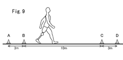
平地歩行動作試験では、10m歩行試験を行った。被験者は図9に示す経路のA地点からD地点までを歩行し、B地点からC地点までの10mの歩行に要する時間を計測した。A地点からB地点、C地点からD地点はどちらも3mの助走区間とした。
平地歩行動作試験では、10m歩行試験を行った。被験者は図9に示す経路のA地点からD地点までを歩行し、B地点からC地点までの10mの歩行に要する時間を計測した。A地点からB地点、C地点からD地点はどちらも3mの助走区間とした。
(2)階段昇り動作試験
階段昇り動作試験では、1段目から11段目までの計10段の段差を昇るのに要する時間を計測した。
階段昇り動作試験では、1段目から11段目までの計10段の段差を昇るのに要する時間を計測した。
(3)階段降り動作試験
階段降り動作試験では、12段目から2段目までの計10段の段差を降りるのに要する時間を計測した。
階段降り動作試験では、12段目から2段目までの計10段の段差を降りるのに要する時間を計測した。
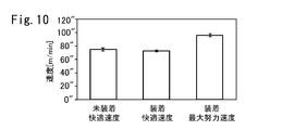
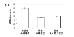
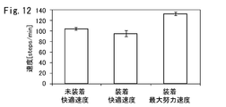
平地歩行動作試験、階段昇り動作試験、階段降り動作試験において、上記実施形態によるトルク制御によって、それぞれの動作が実現できることが確認できた。階段の昇降動作においては、健常者と同じ歩行様式である一足一段での階段昇降動作の実現を確認できた。平地歩行動作試験、階段昇り動作試験、階段降り動作試験の速度結果をそれぞれ図10、図11、図12に示す。
図10より、平地歩行動作試験では、動作補助装置における快適速度と健常者の快適速度が同程度の結果となった。動作補助装置の最大努力速度は健常者の快適速度よりも1.3倍速い結果となった。以上より、下肢切断者が動作補助装置を使用することで健常者と同等な速度で平地歩行を行えると考えられる。
図11より、階段昇り動作では、動作補助装置の快適速度と最大努力速度の両方で、健常者の快適速度より遅い結果となった。動作補助装置の最大努力速度が健常者の快適歩行速度の61%の速度であるという結果となった。以上より、下肢切断者が動作補助装置を使用することで、健常者の60%程度の速度で階段を昇ることができると考えられる。階段昇り動作の速度が健常者より遅くなったのは、動作補助装置では足首が固定され、つま先が段差にあたらないような軌道を生成するために、健常者より大きな軌道を描く必要があるためと考えられる。
図12より、階段降り動作では,動作補助装置の快適速度が健常者の快適速度と同程度の結果となった。動作補助装置の最大努力速度が健常者の快適速度より1.3倍速い結果となった。以上より、下肢切断者が動作補助装置を使用することで健常者と同等な速度で階段を降りることができると考えられる。
タスクの切り替え試験
図13に示す平地歩行動作と階段昇降動作が必要な経路を、動作補助装置を装着した健常1名が歩行し、状況に応じたタスクの切り替えを確認した。使用する階段は5段と3段の段差がそれぞれ両側にあり、5段側の蹴上寸法は120mm、3段側の蹴上寸法は200mmである。図13のA地点から歩行し、B-C区間の階段を昇り、C-D区間の階段を降り、E地点まで歩行する。その後、A地点まで同じ経路を引き返す。
図13に示す平地歩行動作と階段昇降動作が必要な経路を、動作補助装置を装着した健常1名が歩行し、状況に応じたタスクの切り替えを確認した。使用する階段は5段と3段の段差がそれぞれ両側にあり、5段側の蹴上寸法は120mm、3段側の蹴上寸法は200mmである。図13のA地点から歩行し、B-C区間の階段を昇り、C-D区間の階段を降り、E地点まで歩行する。その後、A地点まで同じ経路を引き返す。
図14にこのタスク切り替え試験の結果を示す。図14は、動作の様子と、動作補助装置の膝関節角度と、タスク番号とを示す。タスク番号は、0番が平地歩行タスク、1番が階段昇りタスク、2番が階段降りタスクを示す。上記実施形態によるタスク切り替え制御によって、イッチなどの特殊な装置を用いることなく、装着者の運動意思を読み取り、状況に応じたタスクの切り替えが円滑に行われることを確認した。
[下肢切断者による試験]
下肢切断者1名の協力のもと試験を実施した。試験協力者は交通事故により右大腿と左下腿をそれぞれ切断している50代の男性である。右脚側の膝関節屈曲伸展に必要な筋群の一部が残存しており、随意的に力を入れることができる。試験では、右脚側に動作補助装置を装着し、左脚側には市販されている下腿義足を装着した。義足使用歴は10年であり、平時はインテリジェント義足を使用して、大腿義足の膝関節を屈曲伸展させて平地歩行することができる。
下肢切断者1名の協力のもと試験を実施した。試験協力者は交通事故により右大腿と左下腿をそれぞれ切断している50代の男性である。右脚側の膝関節屈曲伸展に必要な筋群の一部が残存しており、随意的に力を入れることができる。試験では、右脚側に動作補助装置を装着し、左脚側には市販されている下腿義足を装着した。義足使用歴は10年であり、平時はインテリジェント義足を使用して、大腿義足の膝関節を屈曲伸展させて平地歩行することができる。
動作補助装置は、健足側の情報としては床反力のみを使用するため、片大腿切断の患者だけでなく、両下肢切断の本試験協力者にも適用可能である。
生体電位計測試験
動作補助装置の制御に必要な右脚側膝関節の生体電位信号を計測した。試験協力者へ膝関節を屈曲伸展するように力を入れるよう指示し、その際に膨張した筋肉の皮膚表面に生体電位計測用の電極を貼り付けた。動作補助装置によって生体電位の計測を行うと同時に、試験協力者へのフィードバックとして以下の数式(5)に基づく随意制御を行った。

動作補助装置の制御に必要な右脚側膝関節の生体電位信号を計測した。試験協力者へ膝関節を屈曲伸展するように力を入れるよう指示し、その際に膨張した筋肉の皮膚表面に生体電位計測用の電極を貼り付けた。動作補助装置によって生体電位の計測を行うと同時に、試験協力者へのフィードバックとして以下の数式(5)に基づく随意制御を行った。
τBESは随意制御による指令トルク、Efl、Eexはそれぞれ屈曲伸展に伴う生体電位信号の強度、Kfl、Kexはそれぞれ屈曲伸展の生体電位信号から膝関節指令トルクへ変換するゲインである。これにより、試験協力者の生体電位信号に基づいて、動作補助装置の膝関節を屈曲伸展させることができる。
本試験では、試験協力者に膝関節を屈曲伸展させるように指示し、その際に得られた生体電位信号の波形変化と、随意制御によって動作補助装置の膝関節が指示通りに屈曲伸展するかを確認した。
生体電位計測試験の結果を図15に示す。図15において、Knee Angleが動作補助装置の膝関節の角度変化を表し、BES ExtensionとBES Flexionがそれぞれ伸展と屈曲の生体電位信号の強度を示す。生体電位信号の計測結果には100%MVC法を適用した。
屈曲伸展の指示に対応した生体電位信号を取得することができた。図15より、随意制御によって動作補助装置の膝関節を交互に屈曲伸展できること、同時収縮がなく屈曲伸展で独立して生体電位信号を取得できることが確認された。さらに、試験協力者より「自分の脚のように動かせる」、「自分の脚が戻ったみたいだ」との感想を得た。
以上の結果より,試験協力者の随意的な生体電位信号を取得できることが確認できた。さらに、動作補助装置を制御するにあたって十分な生体電位信号の信号強度であることを確認できた。
平地歩行動作試験
下肢切断者が動作補助装置を使用した場合の平地歩行を試験した。本試験では、上述した健常者による試験と同様に、10m歩行試験を行った。図9に示す経路のA地点からD地点までを歩行し、B地点からC地点までの10の歩行に要する時間を計測した。A地点からB地点、C地点からD地点はどちらも3mの助走区間とした。
下肢切断者が動作補助装置を使用した場合の平地歩行を試験した。本試験では、上述した健常者による試験と同様に、10m歩行試験を行った。図9に示す経路のA地点からD地点までを歩行し、B地点からC地点までの10の歩行に要する時間を計測した。A地点からB地点、C地点からD地点はどちらも3mの助走区間とした。
比較のために、動作補助装置を使用した場合と、普段使っている義足(The prosthetic leg used in daily life)を使用した場合の両方で10m歩行試験を行った。
試験協力者には動作補助装置と普段使っている義足の両方で快適速度での歩行を指示した。十分な練習と制御パラメータの調整を行った後に試験を行った。
10歩行試験によって、下肢切断者が動作補助装置を使用して平地歩行ができることが確認できた。図16に動作補助装置を使用した際の1歩行周期分の膝関節角度、股関節角度、両足の床反力、フェイズ番号を示す。膝関節を屈曲伸展させ、支持脚フェイズと遊脚フェイズでフェイズを切り替えながら歩行できていることが確認できた。
図17に、本試験における動作補助装置と普段使っている義足の10m歩行試験に要する時間から算出した速度結果を示す。動作補助装置では39[s]、普段使っている義足では38[s]という結果であった。図17から、動作補助装置と普段使っている義足とで、同程度の歩行速度であることがわかる。
本試験によって、下肢切断者が動作補助装置を使用した場合でも同様に平地歩行を実現することができたことを確認した。普段使っている義足と同程度の速度結果であったことから、日常生活で使用できる歩行速度を実現したと考えられる。
階段昇降動作試験
下肢切断者が動作補助装置を使用した場合の階段昇降を試験した。本試験では、上述した健常者による試験と同じ階段を使用した。階段昇り動作試験では、1段目から11段目までの計10段の段差を昇るのに要する時間を計測した。階段降り動作試験では、12段目から2段目までの計10段の段差を降りるのに要する時間を計測した。片側の手すりは使用可能とした。比較のために、動作補助装置と普段使っている義足の両方で昇降動作時の所要時間の計測を行った。試験協力者にはどちらも快適速度での歩行を指示した。普段使っている義足での試験では、平時での昇降方法が二足一段昇降であるため、二足一段昇降で階段を昇降した。
下肢切断者が動作補助装置を使用した場合の階段昇降を試験した。本試験では、上述した健常者による試験と同じ階段を使用した。階段昇り動作試験では、1段目から11段目までの計10段の段差を昇るのに要する時間を計測した。階段降り動作試験では、12段目から2段目までの計10段の段差を降りるのに要する時間を計測した。片側の手すりは使用可能とした。比較のために、動作補助装置と普段使っている義足の両方で昇降動作時の所要時間の計測を行った。試験協力者にはどちらも快適速度での歩行を指示した。普段使っている義足での試験では、平時での昇降方法が二足一段昇降であるため、二足一段昇降で階段を昇降した。
本試験によって、下肢切断者が動作補助装置を使用して一足一段での階段昇降動作ができることを確認した。図18に階段昇り動作試験において動作補助装置を使用した際の歩行1周期分の膝関節角度、股関節角度、両足の床反力、フェイズ番号を示す。また、図19に階段降り動作試験において動作補助装置を使用した際の歩行1周期分の膝関節角度、膝関節角速度、股関節角度、両足の床反力を示す。
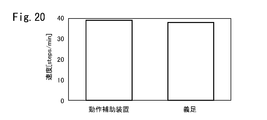
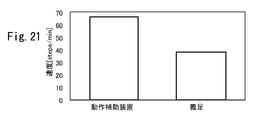
動作補助装置と普段使っている義足の速度結果を図20、図21に示す。図20は階段昇り動作試験の速度結果、図21は階段降り動作試験の速度結果を示す。計測した時間と昇降した階段の段数から、1分間の昇降段数であるケーデンス[steps/min]を算出した。
図20に示す階段昇り動作試験の結果では。動作補助装置と普段使っている義足の両方で同程度の速度結果となった。
図21に示す階段降り動作試験の結果では、動作補助装置使用時の方が、普段使っている義足使用時よりも1.7倍速い結果となった。
階段昇り動作試験において、一般的な受動義足では二足一段であった歩容が、動作補助装置を使用することによって一足一段で階段を昇ることができ、より健常者に近い歩容を実現できた。また、試験協力者から「階段の昇り降りができて楽しい」との感想を得た。これにより、今まで階段を昇ることに対して抱いていた精神的負荷を和らげることができると考えられる。
階段昇り動作において、動作補助装置と普段使っている義足の速度結果における比較では同程度の結果であった。同程度の速度結果となった要因の1つに“慣れ”が考えられる。本試験は1回につき2時間、最短で1週間に1回の頻度で実施した。1回の試験の中で内容説明、装着、生体電位の計測、パラメータの調整などを行うため、訓練にあてる時間はより制限される。日常的な訓練を行うことでより健常者に近い速度で階段を昇ることができるようになると考えられる。別の要因としては、試験協力者が両下肢切断であったことが考えられる。階段昇降動作では、平地歩行に比べて足関節が大きく動作する。両下肢切断の場合には、両脚の足関節の可動域に制限があるため、片大腿切断を模擬した上述の健常者による試験の結果より遅くなったものと考えられる。片大腿切断者が動作補助装置を使用する場合には、健常者による試験結果に近い速度で階段を昇ることができると考えられる。
階段降り動作において、動作補助装置の方が、普段使っている義足より速く降りることができた。これは,普段使っている義足では二足一段であった歩容が、動作補助装置では一足一段での歩容に変わったところが大きいと考えられる。さらに、足裏の土踏まず周辺を段差の角に当て、段差の角を中心に回転させて降りることで足関節の役割を果たし、足関節の可動域が制限されている問題を解決している。
タスクの切り替え試験
図13に示す平地歩行動作と階段昇降動作が必要な経路を、動作補助装置を装着した下肢切断者が歩行し、状況に応じたタスクの切り替えを確認した。使用する階段は5段と3段の段差がそれぞれ両側にあり、5段側の蹴上寸法は120mm、3段側の蹴上寸法は200mmである。図13のA地点から歩行し、B-C区間の階段を昇り、C-D区間の階段を降り、E地点まで歩行する。その後、A地点まで同じ経路を引き返す。
図13に示す平地歩行動作と階段昇降動作が必要な経路を、動作補助装置を装着した下肢切断者が歩行し、状況に応じたタスクの切り替えを確認した。使用する階段は5段と3段の段差がそれぞれ両側にあり、5段側の蹴上寸法は120mm、3段側の蹴上寸法は200mmである。図13のA地点から歩行し、B-C区間の階段を昇り、C-D区間の階段を降り、E地点まで歩行する。その後、A地点まで同じ経路を引き返す。
図22にこのタスク切り替え試験の結果を示す。図22は、動作の様子と、動作補助装置の膝関節角度と、タスク番号と、フェイズ番号とを示す。タスク番号は、0番が平地歩行タスク、1番が階段昇りタスクを示す。タスク番号とフェイズ番号の両方が0の状態で階段を降りる。これは上記実施形態で説明したように、平地歩行タスクの支持脚フェイズと階段降りタスクとで同一のトルク制御としたためである。
図22から、試験協力者が平地歩行と階段昇降の必要な試験用の経路を歩行可能であることが確認できた。さらに、スイッチなどの特殊な装置を用いることなく、タスクが状況に応じて切り替わり、所望の動作を実現できたことが確認できた。
このように、平地歩行に加え、階段昇降の必要な経路において、下肢切断者が単独で歩行可能なことが確認できた。
屋内での使用を想定した歩行試験
日常生活における屋内での使用を想定し、実際の建造物内における平地歩行動作と階段昇降動作の必要な経路を歩行可能か否か確認した。建造物内の模式図を図23に示す。歩行する経路は、A地点から歩行を開始し、Walk1、Ascend、Walk2、Descend、Walk3の順に建造物内を巡回し、A地点へ再び戻ってくるまでの時間を計測した。比較のために、動作補助装置を使用した場合と、普段使っている義足を使用した場合の両方でこの経路を歩行した。普段使っている義足での試験では、平時での昇降方法が二足一段昇降であるため、二足一段昇降で階段を昇降した。
日常生活における屋内での使用を想定し、実際の建造物内における平地歩行動作と階段昇降動作の必要な経路を歩行可能か否か確認した。建造物内の模式図を図23に示す。歩行する経路は、A地点から歩行を開始し、Walk1、Ascend、Walk2、Descend、Walk3の順に建造物内を巡回し、A地点へ再び戻ってくるまでの時間を計測した。比較のために、動作補助装置を使用した場合と、普段使っている義足を使用した場合の両方でこの経路を歩行した。普段使っている義足での試験では、平時での昇降方法が二足一段昇降であるため、二足一段昇降で階段を昇降した。
動作補助装置を使用した場合と普段使っている義足を使用した場合の両方において図23に示す建造物内の歩行を達成した。動作補助装置を使用した場合では、一足一段での階段昇降を行い、試験経路の歩行を達成した。
所要時間は、動作補助装置を使用した場合では160[s]、普段使っている義足を使用した場合では165[s]であった。動作補助装置を使用した方が5[s]速い結果となった。
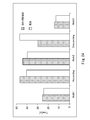
図24に、動作補助装置を使用した場合と、普段使っている義足を使用した場合の、各経路の所要時間を示す。Walk1とWalk3に関しては、両者でほとんど差がなかった。AscendとWalk2では動作補助装置の方が遅い結果となった。Descendに関しては動作補助装置の方が速い結果となった。
階段昇り動作において動作補助装置の方が遅くなった原因としては、本試験では3つのタスク全てに意識を向けなければならず、フェイズの切り替えの多い階段昇りタスクにおいて多少時間がかかったものと考えられる。本試験の経路のような平地歩行と階段昇降の必要な経路においての訓練を続けることで、より無意識的に動作補助装置を使うことができるようになり、移動速度が向上すると考えられる。
本発明を特定の態様を用いて詳細に説明したが、本発明の意図と範囲を離れることなく様々な変更が可能であることは当業者に明らかである。
本出願は、2014年6月13日付で出願された日本特許出願2014-122482に基づいており、その全体が引用により援用される。
本出願は、2014年6月13日付で出願された日本特許出願2014-122482に基づいており、その全体が引用により援用される。
10 ソケット
12 大腿フレーム
14 膝関節部
16 下腿フレーム
18 足部
20 駆動部
30 腰ベルト
40 制御部
50 バッテリ
102 生体電位信号検出手段
104 関節角度検出手段
106 床反力検出手段
110 制御装置
120 駆動信号生成手段
12 大腿フレーム
14 膝関節部
16 下腿フレーム
18 足部
20 駆動部
30 腰ベルト
40 制御部
50 バッテリ
102 生体電位信号検出手段
104 関節角度検出手段
106 床反力検出手段
110 制御装置
120 駆動信号生成手段
Claims (14)
- 義足の大腿フレームと下腿フレームとの間の膝関節の動作を支援する義肢装着式動作補助装置であって、
前記膝関節の外側に配置され、前記大腿フレーム及び前記下腿フレームに連結され、前記義足に対して動力を付与する駆動部と、
鉛直方向に対する股関節角度を検出する絶対角度センサと、
前記駆動部に設けられ、膝関節角度を検出する角度センサと、
装着者への床反力を検出する床反力センサと、
タスクとして分類した装着者の動作パターンを構成する一連の最小動作単位(フェーズ)の各々の基準パラメータを格納したデータ格納部と、
前記股関節角度、前記膝関節角度、及び前記床反力と、前記データ格納部に格納された基準パラメータとを比較することにより、前記装着者のタスクのフェイズを推定し、このフェイズに応じた動力を前記駆動部に発生させるための自律指令信号を生成する制御部と、
を備える義肢装着式動作補助装置。 - 前記制御部は、階段昇りタスクの屈曲フェイズにおいて、前記義足のつま先が所定の高さの段差を超えられるように、前記大腿フレーム及び前記下腿フレームの長さから逆運動学を用いて膝関節目標角度を算出し、該膝関節目標角度と前記角度センサにより検出される膝関節角度との偏差に基づいて前記自律指令信号を生成することを特徴とする請求項1に記載の義肢装着式動作補助装置。
- 前記制御部は、階段昇りタスクの足裏水平フェイズにおいて、前記股関節角度を用いて足裏が水平になる膝関節目標角度を算出し、該膝関節目標角度と前記角度センサにより検出される膝関節角度との偏差に基づいて前記自律指令信号を生成することを特徴とする請求項1又は2に記載の義肢装着式動作補助装置。
- 前記制御部は、前記角度センサにより検出される膝関節角度が前記膝関節目標角度に達すると、屈曲フェイズから足裏水平フェイズに遷移することを特徴とする請求項2に記載の義肢装着式動作補助装置。
- 前記制御部は、階段降りタスク又は平地歩行タスクの支持脚フェイズにおいて、完全伸展角度と前記角度センサにより検出される膝関節角度との偏差にゲインを掛け合わせた値を用いて前記自律指令信号を生成し、
屈曲時のゲインは、伸展時のゲインよりも大きいことを特徴とする請求項1乃至4のいずれかに記載の義肢装着式動作補助装置。 - 前記制御部は、平地歩行タスクの遊脚フェイズにおいて、前記股関節角度から股関節角速度を算出し、所定時間前の股関節角速度にゲインを掛け合わせた値を用いて前記自律指令信号を生成することを特徴とする請求項1乃至5のいずれかに記載の義肢装着式動作補助装置。
- 前記制御部は、前記股関節角度、前記膝関節角度、及び前記床反力に基づいて、平地歩行タスクと階段昇りタスクの切り替えを行うことを特徴とする請求項1乃至6のいずれかに記載の義肢装着式動作補助装置。
- 前記制御部は、健足側床反力、義足側床反力、前記絶対角度センサから得られる鉛直方向加速度、及び前記股関節角度に基づいて、平地歩行タスクから階段昇りタスクへの切り替えを行うことを特徴とする請求項7に記載の義肢装着式動作補助装置。
- 前記制御部は、健足側床反力が所定値以上となり、前記膝関節が屈曲方向に運動している場合、階段昇りタスクから平地歩行タスクへの切り替えを行うことを特徴とする請求項7又は8に記載の義肢装着式動作補助装置。
- 前記制御部は、義足側床反力が所定値以上となり、前記膝関節が伸展方向に運動している場合、階段昇りタスクから平地歩行タスクへの切り替えを行うことを特徴とする請求項7乃至9のいずれかに記載の義肢装着式動作補助装置。
- 前記装着者の大腿部における生体信号を検出する生体信号センサをさらに備え、
前記制御部は、階段昇りタスクにおいて、該生体信号センサにより検出される伸展側の生体信号の強度が所定値以上となった場合に、屈曲フェイズから足裏水平フェイズに遷移することを特徴とする請求項1乃至10のいずれかに記載の義肢装着式動作補助装置。 - 前記制御部は、前記生体信号に応じた動力を前記駆動部に発生させるための随意指令信号を生成し、前記随意指令信号及び前記自律指令信号を合成して合成指令信号を生成し、
前記駆動部は、前記合成指令信号に基づいて生成された駆動電流により駆動することを特徴とする請求項11に記載の義肢装着式動作補助装置。 - 前記データ格納部は、各タスクのフェイズ毎に設定された前記随意指令信号と前記自律指令信号との合成比を格納し、
前記制御部は、推定したフェイズに応じた合成比となるように、前記随意指令信号と前記自律指令信号とを合成して合成指令信号を生成することを特徴とする請求項12に記載の義肢装着式動作補助装置。 - 一端が装着者の大腿部に装着されるソケットに連結される大腿フレームと、
一側が前記大腿フレームに結合される膝関節部と、
一端が前記膝関節部の他側に結合される下腿フレームと、
前記下腿フレームの他端に結合される足部と、
前記膝関節部に設けられ、駆動力の発生により前記大腿フレーム又は前記下腿フレームを回動させる駆動部、及び膝関節角度を検出する角度センサと、
前記大腿フレームに設けられ、鉛直方向に対する股関節角度を検出する絶対角度センサと、
前記足部に設けられ、装着者への床反力を検出する床反力センサと、
タスクとして分類した装着者の動作パターンを構成する一連の最小動作単位(フェーズ)の各々の基準パラメータを格納したデータ格納部と、
前記股関節角度、前記膝関節角度、及び前記床反力と、前記データ格納部に格納された基準パラメータとを比較することにより、前記装着者のタスクのフェイズを推定し、このフェイズに応じた動力を前記駆動部に発生させるための自律指令信号を生成する制御部と、
を備える装着式動作補助装置。
Priority Applications (2)
| Application Number | Priority Date | Filing Date | Title |
|---|---|---|---|
| US15/318,257 US20170119550A1 (en) | 2014-06-13 | 2015-06-12 | Prosthesis-mounted action-assist device and wearable action-assist device |
| EP15807079.7A EP3156010A4 (en) | 2014-06-13 | 2015-06-12 | Worn-prosthetic-limb movement assistance device and worn movement assistance device |
Applications Claiming Priority (2)
| Application Number | Priority Date | Filing Date | Title |
|---|---|---|---|
| JP2014-122482 | 2014-06-13 | ||
| JP2014122482A JP6414664B2 (ja) | 2014-06-13 | 2014-06-13 | 義肢装着式動作補助装置 |
Publications (1)
| Publication Number | Publication Date |
|---|---|
| WO2015190598A1 true WO2015190598A1 (ja) | 2015-12-17 |
Family
ID=54833681
Family Applications (1)
| Application Number | Title | Priority Date | Filing Date |
|---|---|---|---|
| PCT/JP2015/067034 Ceased WO2015190598A1 (ja) | 2014-06-13 | 2015-06-12 | 義肢装着式動作補助装置及び装着式動作補助装置 |
Country Status (4)
| Country | Link |
|---|---|
| US (1) | US20170119550A1 (ja) |
| EP (1) | EP3156010A4 (ja) |
| JP (1) | JP6414664B2 (ja) |
| WO (1) | WO2015190598A1 (ja) |
Cited By (3)
| Publication number | Priority date | Publication date | Assignee | Title |
|---|---|---|---|---|
| CN106109062A (zh) * | 2016-06-14 | 2016-11-16 | 太原理工大学 | 一种基于生物力学的个性化人工膝关节制备方法 |
| CN111658246A (zh) * | 2020-05-19 | 2020-09-15 | 中国科学院计算技术研究所 | 一种基于对称性的智能关节假肢调控方法及系统 |
| CN113977582A (zh) * | 2021-11-12 | 2022-01-28 | 杭州电子科技大学 | 一种基于dmp的下肢外骨骼上楼梯控制方法 |
Families Citing this family (16)
| Publication number | Priority date | Publication date | Assignee | Title |
|---|---|---|---|---|
| US9180025B2 (en) * | 2008-04-21 | 2015-11-10 | Vanderbilt University | Powered leg prosthesis and control methodologies for obtaining near normal gait |
| US11103369B2 (en) | 2016-11-18 | 2021-08-31 | Cyberdyne Inc. | Artificial leg motion assisting apparatus and artificial leg motion assisting method |
| WO2018236208A1 (en) * | 2017-06-22 | 2018-12-27 | Universiti Malaya | A prosthetic limb integrated with a sensory system |
| CA3072504A1 (en) * | 2017-08-29 | 2019-03-07 | Roam Robotics Inc. | Exoskeleton fit evaluation system and method |
| JP6925231B2 (ja) | 2017-10-23 | 2021-08-25 | サンコール株式会社 | 歩行動作補助装置 |
| JP7111463B2 (ja) * | 2017-12-15 | 2022-08-02 | サンコール株式会社 | 歩行動作補助装置 |
| KR20200069033A (ko) * | 2018-12-06 | 2020-06-16 | 한국산업기술대학교산학협력단 | 굴절보조장치를 구비하는 유사 능동형 대퇴 의족 및 유사 능동형 대퇴 의족의 제어방법 |
| WO2020245400A1 (de) * | 2019-06-05 | 2020-12-10 | Otto Bock Healthcare Products Gmbh | Verfahren zum betreiben einer orthopädietechnischen einrichtung und entsprechende einrichtung |
| DE102019115098A1 (de) * | 2019-06-05 | 2020-12-10 | Otto Bock Healthcare Products Gmbh | Verfahren zum Steuern eines künstlichen Kniegelenks |
| DE102019118399A1 (de) * | 2019-07-08 | 2021-01-14 | Georg-August-Universität Göttingen Stiftung Öffentlichen Rechts, Universitätsmedizin | Verfahren und Systeme zum Steuern aktiver Prothesen |
| JP7374014B2 (ja) * | 2020-02-20 | 2023-11-06 | Cyberdyne株式会社 | 装着式動作補助装置 |
| CN111803250A (zh) * | 2020-07-03 | 2020-10-23 | 北京联合大学 | 基于肌电信号和角度信号的膝关节角度预测方法及系统 |
| WO2022087161A1 (en) * | 2020-10-20 | 2022-04-28 | University Of Utah Research Foundation | Powered knee and ankle joint system with adaptive control |
| CN116421372B (zh) * | 2023-03-09 | 2025-01-14 | 南方科技大学 | 控制假肢的方法、假肢和计算机可读存储介质 |
| CN117426914B (zh) * | 2023-12-21 | 2024-03-12 | 深圳市心流科技有限公司 | 假腿模式切换控制方法、控制装置及智能假腿 |
| CN118615076B (zh) * | 2024-08-15 | 2025-02-11 | 浙江强脑科技有限公司 | 假腿上楼梯控制方法、装置和存储介质 |
Citations (3)
| Publication number | Priority date | Publication date | Assignee | Title |
|---|---|---|---|---|
| JP2009060946A (ja) * | 2007-09-04 | 2009-03-26 | Univ Of Tsukuba | 装着式動作補助装置及びその制御方法及びプログラム |
| JP2010017390A (ja) * | 2008-07-11 | 2010-01-28 | Univ Of Tsukuba | 装着式動作補助装置、基準パラメータデータベース構築装置、装着式動作補助装置における駆動制御方法、基準パラメータデータベース構築方法、及びそのプログラム |
| JP2013510603A (ja) * | 2009-11-13 | 2013-03-28 | オットー・ボック・ヘルスケア・プロダクツ・ゲーエムベーハー | 矯正用または補装用の人工の関節を制御するための方法および装置 |
Family Cites Families (8)
| Publication number | Priority date | Publication date | Assignee | Title |
|---|---|---|---|---|
| JP4130739B2 (ja) * | 2002-01-28 | 2008-08-06 | 本田技研工業株式会社 | 二足歩行移動体の床反力推定方法 |
| WO2005087144A2 (en) * | 2004-03-10 | 2005-09-22 | össur hf | Control system and method for a prosthetic knee |
| CN102065799B (zh) * | 2008-06-16 | 2015-03-04 | 伯克利仿生技术公司 | 半驱动式大腿假肢膝关节 |
| US8096965B2 (en) * | 2008-10-13 | 2012-01-17 | Argo Medical Technologies Ltd. | Locomotion assisting device and method |
| KR20110082394A (ko) * | 2010-01-11 | 2011-07-19 | 삼성전자주식회사 | 보행 로봇 및 그 제어 방법 |
| EP2621414B1 (en) * | 2010-09-29 | 2019-03-13 | Össur HF | Prosthetic and orthotic devices and methods and systems for controlling the same |
| JP5642534B2 (ja) * | 2010-12-27 | 2014-12-17 | Cyberdyne株式会社 | 装着式動作補助装置、そのインタフェース装置及びプログラム |
| US9044346B2 (en) * | 2012-03-29 | 2015-06-02 | össur hf | Powered prosthetic hip joint |
-
2014
- 2014-06-13 JP JP2014122482A patent/JP6414664B2/ja active Active
-
2015
- 2015-06-12 US US15/318,257 patent/US20170119550A1/en not_active Abandoned
- 2015-06-12 WO PCT/JP2015/067034 patent/WO2015190598A1/ja not_active Ceased
- 2015-06-12 EP EP15807079.7A patent/EP3156010A4/en not_active Withdrawn
Patent Citations (3)
| Publication number | Priority date | Publication date | Assignee | Title |
|---|---|---|---|---|
| JP2009060946A (ja) * | 2007-09-04 | 2009-03-26 | Univ Of Tsukuba | 装着式動作補助装置及びその制御方法及びプログラム |
| JP2010017390A (ja) * | 2008-07-11 | 2010-01-28 | Univ Of Tsukuba | 装着式動作補助装置、基準パラメータデータベース構築装置、装着式動作補助装置における駆動制御方法、基準パラメータデータベース構築方法、及びそのプログラム |
| JP2013510603A (ja) * | 2009-11-13 | 2013-03-28 | オットー・ボック・ヘルスケア・プロダクツ・ゲーエムベーハー | 矯正用または補装用の人工の関節を制御するための方法および装置 |
Non-Patent Citations (3)
| Title |
|---|
| KENTA SUZUKI ET AL.: "Intention-based walking support for paraplegia patients with Robot Suit HAL", ADVANCED ROBOTICS, vol. 21, no. 12, 2007, pages 1441 - 1469, XP055244781 * |
| See also references of EP3156010A4 * |
| TAKUMI TAKETOMI ET AL.: "Stair Ascent assistance for Cerebral Palsy with Robot Suit HAL", SYSTEM INTEGRATION (SII), 2012 IEEE /SICE INTERNATIONAL SYMPOSIUM ON, 2012, pages 331 - 336, XP032323447 * |
Cited By (3)
| Publication number | Priority date | Publication date | Assignee | Title |
|---|---|---|---|---|
| CN106109062A (zh) * | 2016-06-14 | 2016-11-16 | 太原理工大学 | 一种基于生物力学的个性化人工膝关节制备方法 |
| CN111658246A (zh) * | 2020-05-19 | 2020-09-15 | 中国科学院计算技术研究所 | 一种基于对称性的智能关节假肢调控方法及系统 |
| CN113977582A (zh) * | 2021-11-12 | 2022-01-28 | 杭州电子科技大学 | 一种基于dmp的下肢外骨骼上楼梯控制方法 |
Also Published As
| Publication number | Publication date |
|---|---|
| EP3156010A4 (en) | 2018-07-11 |
| US20170119550A1 (en) | 2017-05-04 |
| EP3156010A1 (en) | 2017-04-19 |
| JP6414664B2 (ja) | 2018-10-31 |
| JP2016002122A (ja) | 2016-01-12 |
Similar Documents
| Publication | Publication Date | Title |
|---|---|---|
| JP6414664B2 (ja) | 義肢装着式動作補助装置 | |
| Huang et al. | Locomotor adaptation by transtibial amputees walking with an experimental powered prosthesis under continuous myoelectric control | |
| Bae et al. | A soft exosuit for patients with stroke: Feasibility study with a mobile off-board actuation unit | |
| US10290235B2 (en) | Rehabilitation using a prosthetic device | |
| Kagawa et al. | Optimization-based motion planning in joint space for walking assistance with wearable robot | |
| Tsukahara et al. | Gait support for complete spinal cord injury patient by synchronized leg-swing with HAL | |
| EP3840714B1 (en) | Bio-inspired adaptive impedance based controller for human-robot interaction | |
| JP5189911B2 (ja) | 装着式動作補助装置、基準パラメータデータベース構築装置、装着式動作補助装置における駆動制御方法、基準パラメータデータベース構築方法、及びそのプログラム | |
| US10799373B2 (en) | Stance controller and related methods | |
| JPWO2012118143A1 (ja) | 歩行訓練装置及び歩行訓練システム | |
| US20180360639A1 (en) | Torque control methods and devices for powered orthosis | |
| WO2018092325A1 (ja) | 義足動作補助装置及び義足動作補助方法 | |
| JP2015177863A (ja) | アシスト制御装置および方法 | |
| Awad et al. | Towards a smart semi-active prosthetic leg: preliminary assessment and testing | |
| Lenzi et al. | Minimum jerk swing control allows variable cadence in powered transfemoral prostheses | |
| JP2012125388A (ja) | 歩行リハビリ装置 | |
| Brantley et al. | Prediction of lower-limb joint kinematics from surface EMG during overground locomotion | |
| Xu et al. | Adaptive stair-ascending and stair-descending strategies for powered lower limb exoskeleton | |
| Yan et al. | A novel adaptive oscillators-based control for a powered multi-joint lower-limb orthosis | |
| Lenzi et al. | Reducing muscle effort in walking through powered exoskeletons | |
| Kagawa et al. | Gait pattern generation for a power-assist device of paraplegic gait | |
| JP2005013442A (ja) | 歩行訓練装置及び歩行訓練装置の制御方法 | |
| Kang et al. | A novel assist-as-needed control method to guide pelvic trajectory for gait rehabilitation | |
| Ekelem et al. | Variable geometry stair ascent and descent controller for a powered lower limb exoskeleton | |
| Yang et al. | Automatic walking pattern transformation method of an assistive device during stair-ground transition |
Legal Events
| Date | Code | Title | Description |
|---|---|---|---|
| 121 | Ep: the epo has been informed by wipo that ep was designated in this application |
Ref document number: 15807079 Country of ref document: EP Kind code of ref document: A1 |
|
| REEP | Request for entry into the european phase |
Ref document number: 2015807079 Country of ref document: EP |
|
| WWE | Wipo information: entry into national phase |
Ref document number: 15318257 Country of ref document: US Ref document number: 2015807079 Country of ref document: EP |
|
| NENP | Non-entry into the national phase |
Ref country code: DE |