WO2015194349A1 - Panneau sandwich en résine et procédé de fabrication de panneau sandwich en résine - Google Patents
Panneau sandwich en résine et procédé de fabrication de panneau sandwich en résine Download PDFInfo
- Publication number
- WO2015194349A1 WO2015194349A1 PCT/JP2015/065699 JP2015065699W WO2015194349A1 WO 2015194349 A1 WO2015194349 A1 WO 2015194349A1 JP 2015065699 W JP2015065699 W JP 2015065699W WO 2015194349 A1 WO2015194349 A1 WO 2015194349A1
- Authority
- WO
- WIPO (PCT)
- Prior art keywords
- resin
- core material
- sandwich panel
- sheet
- skin
- Prior art date
- Legal status (The legal status is an assumption and is not a legal conclusion. Google has not performed a legal analysis and makes no representation as to the accuracy of the status listed.)
- Ceased
Links
Images





Classifications
-
- B—PERFORMING OPERATIONS; TRANSPORTING
- B32—LAYERED PRODUCTS
- B32B—LAYERED PRODUCTS, i.e. PRODUCTS BUILT-UP OF STRATA OF FLAT OR NON-FLAT, e.g. CELLULAR OR HONEYCOMB, FORM
- B32B3/00—Layered products comprising a layer with external or internal discontinuities or unevennesses, or a layer of non-planar shape; Layered products comprising a layer having particular features of form
- B32B3/26—Layered products comprising a layer with external or internal discontinuities or unevennesses, or a layer of non-planar shape; Layered products comprising a layer having particular features of form characterised by a particular shape of the outline of the cross-section of a continuous layer; characterised by a layer with cavities or internal voids ; characterised by an apertured layer
- B32B3/266—Layered products comprising a layer with external or internal discontinuities or unevennesses, or a layer of non-planar shape; Layered products comprising a layer having particular features of form characterised by a particular shape of the outline of the cross-section of a continuous layer; characterised by a layer with cavities or internal voids ; characterised by an apertured layer characterised by an apertured layer, the apertures going through the whole thickness of the layer, e.g. expanded metal, perforated layer, slit layer regular cells B32B3/12
-
- B—PERFORMING OPERATIONS; TRANSPORTING
- B29—WORKING OF PLASTICS; WORKING OF SUBSTANCES IN A PLASTIC STATE IN GENERAL
- B29C—SHAPING OR JOINING OF PLASTICS; SHAPING OF MATERIAL IN A PLASTIC STATE, NOT OTHERWISE PROVIDED FOR; AFTER-TREATMENT OF THE SHAPED PRODUCTS, e.g. REPAIRING
- B29C43/00—Compression moulding, i.e. applying external pressure to flow the moulding material; Apparatus therefor
- B29C43/02—Compression moulding, i.e. applying external pressure to flow the moulding material; Apparatus therefor of articles of definite length, i.e. discrete articles
- B29C43/20—Making multilayered or multicoloured articles
- B29C43/203—Making multilayered articles
- B29C43/206—Making multilayered articles by pressing the material between two preformed layers, e.g. deformable layers
-
- B—PERFORMING OPERATIONS; TRANSPORTING
- B29—WORKING OF PLASTICS; WORKING OF SUBSTANCES IN A PLASTIC STATE IN GENERAL
- B29C—SHAPING OR JOINING OF PLASTICS; SHAPING OF MATERIAL IN A PLASTIC STATE, NOT OTHERWISE PROVIDED FOR; AFTER-TREATMENT OF THE SHAPED PRODUCTS, e.g. REPAIRING
- B29C43/00—Compression moulding, i.e. applying external pressure to flow the moulding material; Apparatus therefor
- B29C43/32—Component parts, details or accessories; Auxiliary operations
- B29C43/56—Compression moulding under special conditions, e.g. vacuum
-
- B—PERFORMING OPERATIONS; TRANSPORTING
- B29—WORKING OF PLASTICS; WORKING OF SUBSTANCES IN A PLASTIC STATE IN GENERAL
- B29C—SHAPING OR JOINING OF PLASTICS; SHAPING OF MATERIAL IN A PLASTIC STATE, NOT OTHERWISE PROVIDED FOR; AFTER-TREATMENT OF THE SHAPED PRODUCTS, e.g. REPAIRING
- B29C65/00—Joining or sealing of preformed parts, e.g. welding of plastics materials; Apparatus therefor
- B29C65/02—Joining or sealing of preformed parts, e.g. welding of plastics materials; Apparatus therefor by heating, with or without pressure
-
- B—PERFORMING OPERATIONS; TRANSPORTING
- B29—WORKING OF PLASTICS; WORKING OF SUBSTANCES IN A PLASTIC STATE IN GENERAL
- B29C—SHAPING OR JOINING OF PLASTICS; SHAPING OF MATERIAL IN A PLASTIC STATE, NOT OTHERWISE PROVIDED FOR; AFTER-TREATMENT OF THE SHAPED PRODUCTS, e.g. REPAIRING
- B29C66/00—General aspects of processes or apparatus for joining preformed parts
- B29C66/70—General aspects of processes or apparatus for joining preformed parts characterised by the composition, physical properties or the structure of the material of the parts to be joined; Joining with non-plastics material
- B29C66/72—General aspects of processes or apparatus for joining preformed parts characterised by the composition, physical properties or the structure of the material of the parts to be joined; Joining with non-plastics material characterised by the structure of the material of the parts to be joined
- B29C66/723—General aspects of processes or apparatus for joining preformed parts characterised by the composition, physical properties or the structure of the material of the parts to be joined; Joining with non-plastics material characterised by the structure of the material of the parts to be joined being multi-layered
-
- B—PERFORMING OPERATIONS; TRANSPORTING
- B29—WORKING OF PLASTICS; WORKING OF SUBSTANCES IN A PLASTIC STATE IN GENERAL
- B29C—SHAPING OR JOINING OF PLASTICS; SHAPING OF MATERIAL IN A PLASTIC STATE, NOT OTHERWISE PROVIDED FOR; AFTER-TREATMENT OF THE SHAPED PRODUCTS, e.g. REPAIRING
- B29C69/00—Combinations of shaping techniques not provided for in a single one of main groups B29C39/00 - B29C67/00, e.g. associations of moulding and joining techniques; Apparatus therefore
-
- B—PERFORMING OPERATIONS; TRANSPORTING
- B32—LAYERED PRODUCTS
- B32B—LAYERED PRODUCTS, i.e. PRODUCTS BUILT-UP OF STRATA OF FLAT OR NON-FLAT, e.g. CELLULAR OR HONEYCOMB, FORM
- B32B27/00—Layered products comprising a layer of synthetic resin
-
- B—PERFORMING OPERATIONS; TRANSPORTING
- B32—LAYERED PRODUCTS
- B32B—LAYERED PRODUCTS, i.e. PRODUCTS BUILT-UP OF STRATA OF FLAT OR NON-FLAT, e.g. CELLULAR OR HONEYCOMB, FORM
- B32B27/00—Layered products comprising a layer of synthetic resin
- B32B27/06—Layered products comprising a layer of synthetic resin as the main or only constituent of a layer, which is next to another layer of the same or of a different material
- B32B27/065—Layered products comprising a layer of synthetic resin as the main or only constituent of a layer, which is next to another layer of the same or of a different material of foam
-
- B—PERFORMING OPERATIONS; TRANSPORTING
- B32—LAYERED PRODUCTS
- B32B—LAYERED PRODUCTS, i.e. PRODUCTS BUILT-UP OF STRATA OF FLAT OR NON-FLAT, e.g. CELLULAR OR HONEYCOMB, FORM
- B32B27/00—Layered products comprising a layer of synthetic resin
- B32B27/06—Layered products comprising a layer of synthetic resin as the main or only constituent of a layer, which is next to another layer of the same or of a different material
- B32B27/08—Layered products comprising a layer of synthetic resin as the main or only constituent of a layer, which is next to another layer of the same or of a different material of synthetic resin
-
- B—PERFORMING OPERATIONS; TRANSPORTING
- B32—LAYERED PRODUCTS
- B32B—LAYERED PRODUCTS, i.e. PRODUCTS BUILT-UP OF STRATA OF FLAT OR NON-FLAT, e.g. CELLULAR OR HONEYCOMB, FORM
- B32B27/00—Layered products comprising a layer of synthetic resin
- B32B27/18—Layered products comprising a layer of synthetic resin characterised by the use of special additives
-
- B—PERFORMING OPERATIONS; TRANSPORTING
- B32—LAYERED PRODUCTS
- B32B—LAYERED PRODUCTS, i.e. PRODUCTS BUILT-UP OF STRATA OF FLAT OR NON-FLAT, e.g. CELLULAR OR HONEYCOMB, FORM
- B32B27/00—Layered products comprising a layer of synthetic resin
- B32B27/18—Layered products comprising a layer of synthetic resin characterised by the use of special additives
- B32B27/20—Layered products comprising a layer of synthetic resin characterised by the use of special additives using fillers, pigments, thixotroping agents
-
- B—PERFORMING OPERATIONS; TRANSPORTING
- B32—LAYERED PRODUCTS
- B32B—LAYERED PRODUCTS, i.e. PRODUCTS BUILT-UP OF STRATA OF FLAT OR NON-FLAT, e.g. CELLULAR OR HONEYCOMB, FORM
- B32B27/00—Layered products comprising a layer of synthetic resin
- B32B27/18—Layered products comprising a layer of synthetic resin characterised by the use of special additives
- B32B27/22—Layered products comprising a layer of synthetic resin characterised by the use of special additives using plasticisers
-
- B—PERFORMING OPERATIONS; TRANSPORTING
- B32—LAYERED PRODUCTS
- B32B—LAYERED PRODUCTS, i.e. PRODUCTS BUILT-UP OF STRATA OF FLAT OR NON-FLAT, e.g. CELLULAR OR HONEYCOMB, FORM
- B32B27/00—Layered products comprising a layer of synthetic resin
- B32B27/30—Layered products comprising a layer of synthetic resin comprising vinyl (co)polymers; comprising acrylic (co)polymers
- B32B27/302—Layered products comprising a layer of synthetic resin comprising vinyl (co)polymers; comprising acrylic (co)polymers comprising aromatic vinyl (co)polymers, e.g. styrenic (co)polymers
-
- B—PERFORMING OPERATIONS; TRANSPORTING
- B32—LAYERED PRODUCTS
- B32B—LAYERED PRODUCTS, i.e. PRODUCTS BUILT-UP OF STRATA OF FLAT OR NON-FLAT, e.g. CELLULAR OR HONEYCOMB, FORM
- B32B27/00—Layered products comprising a layer of synthetic resin
- B32B27/32—Layered products comprising a layer of synthetic resin comprising polyolefins
-
- B—PERFORMING OPERATIONS; TRANSPORTING
- B32—LAYERED PRODUCTS
- B32B—LAYERED PRODUCTS, i.e. PRODUCTS BUILT-UP OF STRATA OF FLAT OR NON-FLAT, e.g. CELLULAR OR HONEYCOMB, FORM
- B32B3/00—Layered products comprising a layer with external or internal discontinuities or unevennesses, or a layer of non-planar shape; Layered products comprising a layer having particular features of form
- B32B3/02—Layered products comprising a layer with external or internal discontinuities or unevennesses, or a layer of non-planar shape; Layered products comprising a layer having particular features of form characterised by features of form at particular places, e.g. in edge regions
- B32B3/04—Layered products comprising a layer with external or internal discontinuities or unevennesses, or a layer of non-planar shape; Layered products comprising a layer having particular features of form characterised by features of form at particular places, e.g. in edge regions characterised by at least one layer folded at the edge, e.g. over another layer ; characterised by at least one layer enveloping or enclosing a material
-
- B—PERFORMING OPERATIONS; TRANSPORTING
- B32—LAYERED PRODUCTS
- B32B—LAYERED PRODUCTS, i.e. PRODUCTS BUILT-UP OF STRATA OF FLAT OR NON-FLAT, e.g. CELLULAR OR HONEYCOMB, FORM
- B32B3/00—Layered products comprising a layer with external or internal discontinuities or unevennesses, or a layer of non-planar shape; Layered products comprising a layer having particular features of form
- B32B3/26—Layered products comprising a layer with external or internal discontinuities or unevennesses, or a layer of non-planar shape; Layered products comprising a layer having particular features of form characterised by a particular shape of the outline of the cross-section of a continuous layer; characterised by a layer with cavities or internal voids ; characterised by an apertured layer
- B32B3/30—Layered products comprising a layer with external or internal discontinuities or unevennesses, or a layer of non-planar shape; Layered products comprising a layer having particular features of form characterised by a particular shape of the outline of the cross-section of a continuous layer; characterised by a layer with cavities or internal voids ; characterised by an apertured layer characterised by a layer formed with recesses or projections, e.g. hollows, grooves, protuberances, ribs
-
- B—PERFORMING OPERATIONS; TRANSPORTING
- B32—LAYERED PRODUCTS
- B32B—LAYERED PRODUCTS, i.e. PRODUCTS BUILT-UP OF STRATA OF FLAT OR NON-FLAT, e.g. CELLULAR OR HONEYCOMB, FORM
- B32B37/00—Methods or apparatus for laminating, e.g. by curing or by ultrasonic bonding
- B32B37/14—Methods or apparatus for laminating, e.g. by curing or by ultrasonic bonding characterised by the properties of the layers
- B32B37/15—Methods or apparatus for laminating, e.g. by curing or by ultrasonic bonding characterised by the properties of the layers with at least one layer being manufactured and immediately laminated before reaching its stable state, e.g. in which a layer is extruded and laminated while in semi-molten state
- B32B37/153—Methods or apparatus for laminating, e.g. by curing or by ultrasonic bonding characterised by the properties of the layers with at least one layer being manufactured and immediately laminated before reaching its stable state, e.g. in which a layer is extruded and laminated while in semi-molten state at least one layer is extruded and immediately laminated while in semi-molten state
-
- B—PERFORMING OPERATIONS; TRANSPORTING
- B32—LAYERED PRODUCTS
- B32B—LAYERED PRODUCTS, i.e. PRODUCTS BUILT-UP OF STRATA OF FLAT OR NON-FLAT, e.g. CELLULAR OR HONEYCOMB, FORM
- B32B37/00—Methods or apparatus for laminating, e.g. by curing or by ultrasonic bonding
- B32B37/14—Methods or apparatus for laminating, e.g. by curing or by ultrasonic bonding characterised by the properties of the layers
- B32B37/16—Methods or apparatus for laminating, e.g. by curing or by ultrasonic bonding characterised by the properties of the layers with all layers existing as coherent layers before laminating
- B32B37/18—Methods or apparatus for laminating, e.g. by curing or by ultrasonic bonding characterised by the properties of the layers with all layers existing as coherent layers before laminating involving the assembly of discrete sheets or panels only
- B32B37/182—Methods or apparatus for laminating, e.g. by curing or by ultrasonic bonding characterised by the properties of the layers with all layers existing as coherent layers before laminating involving the assembly of discrete sheets or panels only one or more of the layers being plastic
-
- B—PERFORMING OPERATIONS; TRANSPORTING
- B32—LAYERED PRODUCTS
- B32B—LAYERED PRODUCTS, i.e. PRODUCTS BUILT-UP OF STRATA OF FLAT OR NON-FLAT, e.g. CELLULAR OR HONEYCOMB, FORM
- B32B38/00—Ancillary operations in connection with laminating processes
- B32B38/0004—Cutting, tearing or severing, e.g. bursting; Cutter details
-
- B—PERFORMING OPERATIONS; TRANSPORTING
- B32—LAYERED PRODUCTS
- B32B—LAYERED PRODUCTS, i.e. PRODUCTS BUILT-UP OF STRATA OF FLAT OR NON-FLAT, e.g. CELLULAR OR HONEYCOMB, FORM
- B32B38/00—Ancillary operations in connection with laminating processes
- B32B38/18—Handling of layers or the laminate
- B32B38/1858—Handling of layers or the laminate using vacuum
-
- B—PERFORMING OPERATIONS; TRANSPORTING
- B32—LAYERED PRODUCTS
- B32B—LAYERED PRODUCTS, i.e. PRODUCTS BUILT-UP OF STRATA OF FLAT OR NON-FLAT, e.g. CELLULAR OR HONEYCOMB, FORM
- B32B5/00—Layered products characterised by the non- homogeneity or physical structure, i.e. comprising a fibrous, filamentary, particulate or foam layer; Layered products characterised by having a layer differing constitutionally or physically in different parts
- B32B5/18—Layered products characterised by the non- homogeneity or physical structure, i.e. comprising a fibrous, filamentary, particulate or foam layer; Layered products characterised by having a layer differing constitutionally or physically in different parts characterised by features of a layer of foamed material
-
- B—PERFORMING OPERATIONS; TRANSPORTING
- B32—LAYERED PRODUCTS
- B32B—LAYERED PRODUCTS, i.e. PRODUCTS BUILT-UP OF STRATA OF FLAT OR NON-FLAT, e.g. CELLULAR OR HONEYCOMB, FORM
- B32B7/00—Layered products characterised by the relation between layers; Layered products characterised by the relative orientation of features between layers, or by the relative values of a measurable parameter between layers, i.e. products comprising layers having different physical, chemical or physicochemical properties; Layered products characterised by the interconnection of layers
- B32B7/04—Interconnection of layers
- B32B7/05—Interconnection of layers the layers not being connected over the whole surface, e.g. discontinuous connection or patterned connection
-
- B—PERFORMING OPERATIONS; TRANSPORTING
- B32—LAYERED PRODUCTS
- B32B—LAYERED PRODUCTS, i.e. PRODUCTS BUILT-UP OF STRATA OF FLAT OR NON-FLAT, e.g. CELLULAR OR HONEYCOMB, FORM
- B32B7/00—Layered products characterised by the relation between layers; Layered products characterised by the relative orientation of features between layers, or by the relative values of a measurable parameter between layers, i.e. products comprising layers having different physical, chemical or physicochemical properties; Layered products characterised by the interconnection of layers
- B32B7/04—Interconnection of layers
- B32B7/12—Interconnection of layers using interposed adhesives or interposed materials with bonding properties
-
- B—PERFORMING OPERATIONS; TRANSPORTING
- B29—WORKING OF PLASTICS; WORKING OF SUBSTANCES IN A PLASTIC STATE IN GENERAL
- B29C—SHAPING OR JOINING OF PLASTICS; SHAPING OF MATERIAL IN A PLASTIC STATE, NOT OTHERWISE PROVIDED FOR; AFTER-TREATMENT OF THE SHAPED PRODUCTS, e.g. REPAIRING
- B29C43/00—Compression moulding, i.e. applying external pressure to flow the moulding material; Apparatus therefor
- B29C43/02—Compression moulding, i.e. applying external pressure to flow the moulding material; Apparatus therefor of articles of definite length, i.e. discrete articles
- B29C43/18—Compression moulding, i.e. applying external pressure to flow the moulding material; Apparatus therefor of articles of definite length, i.e. discrete articles incorporating preformed parts or layers, e.g. compression moulding around inserts or for coating articles
- B29C2043/181—Compression moulding, i.e. applying external pressure to flow the moulding material; Apparatus therefor of articles of definite length, i.e. discrete articles incorporating preformed parts or layers, e.g. compression moulding around inserts or for coating articles encapsulated
- B29C2043/182—Compression moulding, i.e. applying external pressure to flow the moulding material; Apparatus therefor of articles of definite length, i.e. discrete articles incorporating preformed parts or layers, e.g. compression moulding around inserts or for coating articles encapsulated completely
-
- B—PERFORMING OPERATIONS; TRANSPORTING
- B29—WORKING OF PLASTICS; WORKING OF SUBSTANCES IN A PLASTIC STATE IN GENERAL
- B29C—SHAPING OR JOINING OF PLASTICS; SHAPING OF MATERIAL IN A PLASTIC STATE, NOT OTHERWISE PROVIDED FOR; AFTER-TREATMENT OF THE SHAPED PRODUCTS, e.g. REPAIRING
- B29C43/00—Compression moulding, i.e. applying external pressure to flow the moulding material; Apparatus therefor
- B29C43/32—Component parts, details or accessories; Auxiliary operations
- B29C43/56—Compression moulding under special conditions, e.g. vacuum
- B29C2043/561—Compression moulding under special conditions, e.g. vacuum under vacuum conditions
- B29C2043/563—Compression moulding under special conditions, e.g. vacuum under vacuum conditions combined with mechanical pressure, i.e. mould plates, rams, stampers
-
- B—PERFORMING OPERATIONS; TRANSPORTING
- B29—WORKING OF PLASTICS; WORKING OF SUBSTANCES IN A PLASTIC STATE IN GENERAL
- B29C—SHAPING OR JOINING OF PLASTICS; SHAPING OF MATERIAL IN A PLASTIC STATE, NOT OTHERWISE PROVIDED FOR; AFTER-TREATMENT OF THE SHAPED PRODUCTS, e.g. REPAIRING
- B29C48/00—Extrusion moulding, i.e. expressing the moulding material through a die or nozzle which imparts the desired form; Apparatus therefor
- B29C48/001—Combinations of extrusion moulding with other shaping operations
- B29C48/0017—Combinations of extrusion moulding with other shaping operations combined with blow-moulding or thermoforming
-
- B—PERFORMING OPERATIONS; TRANSPORTING
- B29—WORKING OF PLASTICS; WORKING OF SUBSTANCES IN A PLASTIC STATE IN GENERAL
- B29K—INDEXING SCHEME ASSOCIATED WITH SUBCLASSES B29B, B29C OR B29D, RELATING TO MOULDING MATERIALS OR TO MATERIALS FOR MOULDS, REINFORCEMENTS, FILLERS OR PREFORMED PARTS, e.g. INSERTS
- B29K2101/00—Use of unspecified macromolecular compounds as moulding material
- B29K2101/12—Thermoplastic materials
-
- B—PERFORMING OPERATIONS; TRANSPORTING
- B29—WORKING OF PLASTICS; WORKING OF SUBSTANCES IN A PLASTIC STATE IN GENERAL
- B29L—INDEXING SCHEME ASSOCIATED WITH SUBCLASS B29C, RELATING TO PARTICULAR ARTICLES
- B29L2031/00—Other particular articles
- B29L2031/30—Vehicles, e.g. ships or aircraft, or body parts thereof
-
- B—PERFORMING OPERATIONS; TRANSPORTING
- B32—LAYERED PRODUCTS
- B32B—LAYERED PRODUCTS, i.e. PRODUCTS BUILT-UP OF STRATA OF FLAT OR NON-FLAT, e.g. CELLULAR OR HONEYCOMB, FORM
- B32B2250/00—Layers arrangement
- B32B2250/03—3 layers
-
- B—PERFORMING OPERATIONS; TRANSPORTING
- B32—LAYERED PRODUCTS
- B32B—LAYERED PRODUCTS, i.e. PRODUCTS BUILT-UP OF STRATA OF FLAT OR NON-FLAT, e.g. CELLULAR OR HONEYCOMB, FORM
- B32B2250/00—Layers arrangement
- B32B2250/24—All layers being polymeric
-
- B—PERFORMING OPERATIONS; TRANSPORTING
- B32—LAYERED PRODUCTS
- B32B—LAYERED PRODUCTS, i.e. PRODUCTS BUILT-UP OF STRATA OF FLAT OR NON-FLAT, e.g. CELLULAR OR HONEYCOMB, FORM
- B32B2250/00—Layers arrangement
- B32B2250/40—Symmetrical or sandwich layers, e.g. ABA, ABCBA, ABCCBA
-
- B—PERFORMING OPERATIONS; TRANSPORTING
- B32—LAYERED PRODUCTS
- B32B—LAYERED PRODUCTS, i.e. PRODUCTS BUILT-UP OF STRATA OF FLAT OR NON-FLAT, e.g. CELLULAR OR HONEYCOMB, FORM
- B32B2262/00—Composition or structural features of fibres which form a fibrous or filamentary layer or are present as additives
- B32B2262/10—Inorganic fibres
- B32B2262/101—Glass fibres
-
- B—PERFORMING OPERATIONS; TRANSPORTING
- B32—LAYERED PRODUCTS
- B32B—LAYERED PRODUCTS, i.e. PRODUCTS BUILT-UP OF STRATA OF FLAT OR NON-FLAT, e.g. CELLULAR OR HONEYCOMB, FORM
- B32B2262/00—Composition or structural features of fibres which form a fibrous or filamentary layer or are present as additives
- B32B2262/10—Inorganic fibres
- B32B2262/106—Carbon fibres, e.g. graphite fibres
-
- B—PERFORMING OPERATIONS; TRANSPORTING
- B32—LAYERED PRODUCTS
- B32B—LAYERED PRODUCTS, i.e. PRODUCTS BUILT-UP OF STRATA OF FLAT OR NON-FLAT, e.g. CELLULAR OR HONEYCOMB, FORM
- B32B2264/00—Composition or properties of particles which form a particulate layer or are present as additives
- B32B2264/10—Inorganic particles
- B32B2264/102—Oxide or hydroxide
-
- B—PERFORMING OPERATIONS; TRANSPORTING
- B32—LAYERED PRODUCTS
- B32B—LAYERED PRODUCTS, i.e. PRODUCTS BUILT-UP OF STRATA OF FLAT OR NON-FLAT, e.g. CELLULAR OR HONEYCOMB, FORM
- B32B2264/00—Composition or properties of particles which form a particulate layer or are present as additives
- B32B2264/10—Inorganic particles
- B32B2264/104—Oxysalt, e.g. carbonate, sulfate, phosphate or nitrate particles
-
- B—PERFORMING OPERATIONS; TRANSPORTING
- B32—LAYERED PRODUCTS
- B32B—LAYERED PRODUCTS, i.e. PRODUCTS BUILT-UP OF STRATA OF FLAT OR NON-FLAT, e.g. CELLULAR OR HONEYCOMB, FORM
- B32B2266/00—Composition of foam
- B32B2266/02—Organic
- B32B2266/0207—Materials belonging to B32B25/00
-
- B—PERFORMING OPERATIONS; TRANSPORTING
- B32—LAYERED PRODUCTS
- B32B—LAYERED PRODUCTS, i.e. PRODUCTS BUILT-UP OF STRATA OF FLAT OR NON-FLAT, e.g. CELLULAR OR HONEYCOMB, FORM
- B32B2266/00—Composition of foam
- B32B2266/02—Organic
- B32B2266/0214—Materials belonging to B32B27/00
-
- B—PERFORMING OPERATIONS; TRANSPORTING
- B32—LAYERED PRODUCTS
- B32B—LAYERED PRODUCTS, i.e. PRODUCTS BUILT-UP OF STRATA OF FLAT OR NON-FLAT, e.g. CELLULAR OR HONEYCOMB, FORM
- B32B2266/00—Composition of foam
- B32B2266/02—Organic
- B32B2266/0214—Materials belonging to B32B27/00
- B32B2266/0221—Vinyl resin
-
- B—PERFORMING OPERATIONS; TRANSPORTING
- B32—LAYERED PRODUCTS
- B32B—LAYERED PRODUCTS, i.e. PRODUCTS BUILT-UP OF STRATA OF FLAT OR NON-FLAT, e.g. CELLULAR OR HONEYCOMB, FORM
- B32B2266/00—Composition of foam
- B32B2266/02—Organic
- B32B2266/0214—Materials belonging to B32B27/00
- B32B2266/0221—Vinyl resin
- B32B2266/0228—Aromatic vinyl resin, e.g. styrenic (co)polymers
-
- B—PERFORMING OPERATIONS; TRANSPORTING
- B32—LAYERED PRODUCTS
- B32B—LAYERED PRODUCTS, i.e. PRODUCTS BUILT-UP OF STRATA OF FLAT OR NON-FLAT, e.g. CELLULAR OR HONEYCOMB, FORM
- B32B2266/00—Composition of foam
- B32B2266/02—Organic
- B32B2266/0214—Materials belonging to B32B27/00
- B32B2266/0221—Vinyl resin
- B32B2266/0235—Vinyl halide, e.g. PVC, PVDC, PVF, PVDF
-
- B—PERFORMING OPERATIONS; TRANSPORTING
- B32—LAYERED PRODUCTS
- B32B—LAYERED PRODUCTS, i.e. PRODUCTS BUILT-UP OF STRATA OF FLAT OR NON-FLAT, e.g. CELLULAR OR HONEYCOMB, FORM
- B32B2266/00—Composition of foam
- B32B2266/02—Organic
- B32B2266/0214—Materials belonging to B32B27/00
- B32B2266/0242—Acrylic resin
-
- B—PERFORMING OPERATIONS; TRANSPORTING
- B32—LAYERED PRODUCTS
- B32B—LAYERED PRODUCTS, i.e. PRODUCTS BUILT-UP OF STRATA OF FLAT OR NON-FLAT, e.g. CELLULAR OR HONEYCOMB, FORM
- B32B2266/00—Composition of foam
- B32B2266/02—Organic
- B32B2266/0214—Materials belonging to B32B27/00
- B32B2266/025—Polyolefin
-
- B—PERFORMING OPERATIONS; TRANSPORTING
- B32—LAYERED PRODUCTS
- B32B—LAYERED PRODUCTS, i.e. PRODUCTS BUILT-UP OF STRATA OF FLAT OR NON-FLAT, e.g. CELLULAR OR HONEYCOMB, FORM
- B32B2266/00—Composition of foam
- B32B2266/02—Organic
- B32B2266/0214—Materials belonging to B32B27/00
- B32B2266/0257—Polyamide
-
- B—PERFORMING OPERATIONS; TRANSPORTING
- B32—LAYERED PRODUCTS
- B32B—LAYERED PRODUCTS, i.e. PRODUCTS BUILT-UP OF STRATA OF FLAT OR NON-FLAT, e.g. CELLULAR OR HONEYCOMB, FORM
- B32B2266/00—Composition of foam
- B32B2266/02—Organic
- B32B2266/0214—Materials belonging to B32B27/00
- B32B2266/0264—Polyester
-
- B—PERFORMING OPERATIONS; TRANSPORTING
- B32—LAYERED PRODUCTS
- B32B—LAYERED PRODUCTS, i.e. PRODUCTS BUILT-UP OF STRATA OF FLAT OR NON-FLAT, e.g. CELLULAR OR HONEYCOMB, FORM
- B32B2266/00—Composition of foam
- B32B2266/02—Organic
- B32B2266/0214—Materials belonging to B32B27/00
- B32B2266/0285—Condensation resins of aldehydes, e.g. with phenols, ureas, melamines
-
- B—PERFORMING OPERATIONS; TRANSPORTING
- B32—LAYERED PRODUCTS
- B32B—LAYERED PRODUCTS, i.e. PRODUCTS BUILT-UP OF STRATA OF FLAT OR NON-FLAT, e.g. CELLULAR OR HONEYCOMB, FORM
- B32B2266/00—Composition of foam
- B32B2266/02—Organic
- B32B2266/0214—Materials belonging to B32B27/00
- B32B2266/0292—Thermoplastic elastomer
-
- B—PERFORMING OPERATIONS; TRANSPORTING
- B32—LAYERED PRODUCTS
- B32B—LAYERED PRODUCTS, i.e. PRODUCTS BUILT-UP OF STRATA OF FLAT OR NON-FLAT, e.g. CELLULAR OR HONEYCOMB, FORM
- B32B2274/00—Thermoplastic elastomer material
-
- B—PERFORMING OPERATIONS; TRANSPORTING
- B32—LAYERED PRODUCTS
- B32B—LAYERED PRODUCTS, i.e. PRODUCTS BUILT-UP OF STRATA OF FLAT OR NON-FLAT, e.g. CELLULAR OR HONEYCOMB, FORM
- B32B2305/00—Condition, form or state of the layers or laminate
- B32B2305/02—Cellular or porous
-
- B—PERFORMING OPERATIONS; TRANSPORTING
- B32—LAYERED PRODUCTS
- B32B—LAYERED PRODUCTS, i.e. PRODUCTS BUILT-UP OF STRATA OF FLAT OR NON-FLAT, e.g. CELLULAR OR HONEYCOMB, FORM
- B32B2307/00—Properties of the layers or laminate
- B32B2307/50—Properties of the layers or laminate having particular mechanical properties
- B32B2307/54—Yield strength; Tensile strength
-
- B—PERFORMING OPERATIONS; TRANSPORTING
- B32—LAYERED PRODUCTS
- B32B—LAYERED PRODUCTS, i.e. PRODUCTS BUILT-UP OF STRATA OF FLAT OR NON-FLAT, e.g. CELLULAR OR HONEYCOMB, FORM
- B32B2307/00—Properties of the layers or laminate
- B32B2307/50—Properties of the layers or laminate having particular mechanical properties
- B32B2307/546—Flexural strength; Flexion stiffness
-
- B—PERFORMING OPERATIONS; TRANSPORTING
- B32—LAYERED PRODUCTS
- B32B—LAYERED PRODUCTS, i.e. PRODUCTS BUILT-UP OF STRATA OF FLAT OR NON-FLAT, e.g. CELLULAR OR HONEYCOMB, FORM
- B32B2307/00—Properties of the layers or laminate
- B32B2307/70—Other properties
- B32B2307/718—Weight, e.g. weight per square meter
-
- B—PERFORMING OPERATIONS; TRANSPORTING
- B32—LAYERED PRODUCTS
- B32B—LAYERED PRODUCTS, i.e. PRODUCTS BUILT-UP OF STRATA OF FLAT OR NON-FLAT, e.g. CELLULAR OR HONEYCOMB, FORM
- B32B2398/00—Unspecified macromolecular compounds
- B32B2398/20—Thermoplastics
-
- B—PERFORMING OPERATIONS; TRANSPORTING
- B32—LAYERED PRODUCTS
- B32B—LAYERED PRODUCTS, i.e. PRODUCTS BUILT-UP OF STRATA OF FLAT OR NON-FLAT, e.g. CELLULAR OR HONEYCOMB, FORM
- B32B2419/00—Buildings or parts thereof
-
- B—PERFORMING OPERATIONS; TRANSPORTING
- B32—LAYERED PRODUCTS
- B32B—LAYERED PRODUCTS, i.e. PRODUCTS BUILT-UP OF STRATA OF FLAT OR NON-FLAT, e.g. CELLULAR OR HONEYCOMB, FORM
- B32B2419/00—Buildings or parts thereof
- B32B2419/06—Roofs, roof membranes
-
- B—PERFORMING OPERATIONS; TRANSPORTING
- B32—LAYERED PRODUCTS
- B32B—LAYERED PRODUCTS, i.e. PRODUCTS BUILT-UP OF STRATA OF FLAT OR NON-FLAT, e.g. CELLULAR OR HONEYCOMB, FORM
- B32B2605/00—Vehicles
-
- B—PERFORMING OPERATIONS; TRANSPORTING
- B32—LAYERED PRODUCTS
- B32B—LAYERED PRODUCTS, i.e. PRODUCTS BUILT-UP OF STRATA OF FLAT OR NON-FLAT, e.g. CELLULAR OR HONEYCOMB, FORM
- B32B2607/00—Walls, panels
Definitions
- the present invention relates to a resin sandwich panel, and more particularly, to a resin sandwich panel that can ensure the required rigidity without causing molding defects while maintaining the aesthetic appearance.
- sandwich panels have been used for various purposes such as transportation equipment for automobiles, aircrafts, etc., building materials, floors for beds, housings for electrical equipment, sports and leisure.
- the sandwich panel has two skin material sheets and a core material interposed between both skin material sheets, and the laminated structure of the skin material sheet, the core material and the skin material sheet is a basic form.
- an exterior aesthetic is important, such as an interior panel used in a bathroom, but if not so strong, a cosmetic material is applied to the front side skin sheet that has an appearance.
- emphasis is placed on the surface properties or the overall molded shape of the decorative material, and in the case of use as a structural material, strength is required from the appearance of appearance.
- a resin sandwich panel when used as a cargo floor lid of an automobile, it is used not only for aesthetic appearance but also for placing heavy loads on the cargo floor lid. While rigidity that can withstand the weight of the load (especially bending rigidity) is required, weight reduction is required from the viewpoint of improving fuel efficiency, and it is necessary to overcome technical challenges that are difficult to achieve both high rigidity and light weight. is there. Therefore, as a resin-made sandwich panel for such applications, a hard resin material with a high Young's modulus is adopted as the skin material sheet, while a core (thickness of the core material) is used as a core material.
- Patent Document 1 and Patent Document 2 are common as sandwich structures for interior material panels such as automobile deck boards or floor panels, and Patent Document 1 discloses a two-piece melted parison between divided molds. Is disclosed, and a resin core material 13 such as polypropylene formed in advance between two melted parisons is placed and pressed into a split mold by vacuum or compressed air to be molded.
- a resin core material 13 such as polypropylene formed in advance between two melted parisons is placed and pressed into a split mold by vacuum or compressed air to be molded.
- Patent Document 2 in the upper and lower divided molds, a pre-formed back side sheet material softened by reheating is placed on the lower mold, and then the back side sheet material is vacuum sucked through the lower mold. And then placing a foamed resin such as polyethylene on the back side sheet material, and re-heating the softened front side sheet material on the foamed resin. It discloses that the sandwich structure is formed by placing and then clamping with vacuum suction through the upper and lower molds. According to the sandwich panel as described above, it is possible to reduce the weight by forming bubbles by foaming.
- thermoplastic resin sheet facing the surface of the resin core material 13 is welded, air exists between them, so that air pockets of various sizes are single or unexpectedly located at an unexpected position. There are cases where a plurality of these are formed, resulting in the following technical problems.
- Peeling is likely to cause welding peeling, and even if molding failure is caused or not molding failure, the rigidity of the entire resin sandwich panel is reduced due to insufficient welding.
- the aesthetic appearance as a resin sandwich panel is impaired. More specifically, as described above, when the area of the air pool expands by clamping the split mold, a portion corresponding to the air pool area of the outer surface of the thermoplastic resin sheet partially swells, The flatness of the outer surface of the thermoplastic resin sheet is lost, and the aesthetic appearance as a resin sandwich panel is impaired. It is technically difficult to perform mold clamping of the divided mold after eliminating such air pockets in advance.
- an object of the present invention is to provide a resin sandwich panel capable of ensuring the necessary rigidity without causing molding defects while maintaining aesthetic appearance.
- the resin sandwich panel of the present invention comprises: In a sandwich panel having two resin skin sheets and a resin core material that is surface-bonded to both skin sheets in a form sandwiched between both skin sheets,
- the two resin skin sheets are formed by forming a hollow portion inside by joining the peripheral edges of each other, and the resin core material is disposed in the hollow portion, At least one of the surfaces of the resin core material facing the two resin skin sheets is provided with a groove extending over the entire surface and a recessed portion communicating with the groove.
- At least one of the two resin skin sheets is provided with an air opening through hole in its thickness direction, whereby, when the resin skin material sheet corresponding to the at least one surface of the resin core material is surface-bonded in the hollow portion, the resin skin material sheet corresponding to the at least one surface; The air between is guided to the recessed portion through the groove portion and exhausted from the atmosphere opening through hole.
- a groove portion stretched over the entire surface on at least one of the surfaces of the resin core material facing the two resin skin sheets, and the groove portion Since there is a recessed portion that communicates, when the surface of the resin core material on the groove side and the resin skin material sheet facing it are surface-bonded, an air pocket is unexpectedly formed between them.
- the air accumulated in the air reservoir can be accumulated in the recessed portion through the groove portion, and can be exhausted from the atmosphere opening hole through the groove portion, and the groove portion functions as an air vent, for example,
- the recessed portion is an internal space closed by a corresponding resin skin material sheet on at least one of the surfaces of the resin core material, and may penetrate in the thickness direction of the resin core material, You don't have to.
- the concave portion in the at least one surface, forms an opening and extends inward, and constitutes a gap that is closed by the corresponding resin skin sheet, inside,
- the area of the opening is set so that the surface adhesion between the at least one surface and the corresponding resin skin sheet is sufficient
- the volume of the air gap is such that the air guided to the recessed portion through the groove portion when the resin skin material sheet corresponding to the at least one surface of the resin core material is surface-bonded in the hollow portion. Therefore, it is preferable that the pressure is set to be sufficient to suppress an increase in internal pressure in the gap.
- the resin core material is solid, and the recessed portion is configured by forming the gap in the solid portion.
- the resin core material is constituted by a pair of thermoplastic resin plate materials, and the recessed portion forms an opening on one surface of the pair of thermoplastic resin plate materials, and the other heat on the inner surface side. It is comprised by the cyclic
- the groove may be provided with a single long groove in a curved shape.
- a plurality of annular grooves may be provided in a nested manner in the groove portion, and at least adjacent grooves may communicate with each other.
- the groove portion is provided in a lattice shape, and includes a first groove portion group extending in parallel to the long side of the resin core material and a second groove portion group extending in parallel to the short side of the resin core material. It may be done.
- the resin core material is a foamed resin having a predetermined expansion ratio
- the resin skin sheet facing the at least one surface of the resin core material is bonded to the bottom surface of the groove portion. It may be.
- the groove is provided on each surface of the resin core material, The recessed portion may be provided so as to penetrate in the thickness direction of the resin core material.
- At least one of the two resin skin sheets may be further provided with an air opening through hole communicating with the groove in the thickness direction.
- the air opening through hole is formed by penetrating a stab needle into at least one of the two resin skin sheets,
- the recessed portion may be provided on a portion corresponding to the air opening through hole on the at least one surface of the resin core material so as to be sufficient to avoid interference with a puncture needle.
- the two resin skin sheets form a peripheral space around the resin core by joining the peripheral edges of each other,
- the groove portion is provided so as to come out to the outer edge of the resin core material, whereby the groove portion is configured to communicate with the outer peripheral space portion,
- the air opening through hole may be formed by penetrating a puncture needle at a position corresponding to the outer peripheral space of at least one of the two resin skin sheets.
- the air opening through hole is formed by penetrating a stab needle into at least one of the two resin skin sheets, On the at least one surface of the resin core material, a concave portion having a space sufficient to avoid interference with a puncture needle is provided at a portion corresponding to the air opening through hole, and the concave portion via the groove portion. It may be provided so as to communicate. Further, the air opening through hole is provided at a position corresponding to the flow path of the groove portion, and the groove portion is surface-bonded to the resin skin material sheet corresponding to the at least one surface of the resin core material. It may be formed as a permanent groove that does not disappear.
- the two resin skin sheets form a peripheral space around the resin core material by joining the peripheral edges of each other,
- the groove portion may be formed in a lattice shape that goes out to the outer edge of the resin core material, whereby the lattice-shaped groove portion may communicate with the outer peripheral space portion.
- the resin sandwich panel of the present invention comprises: In a sandwich panel having two resin skin sheets and a resin core material that is surface-bonded to both skin sheets in a form sandwiched between both skin sheets,
- the two resin skin sheets are formed by forming the outer peripheral space around the resin core material by joining the peripheral edges of each other.
- At least one of the surfaces of the resin core material facing the two resin skin sheets is provided with a lattice-like groove portion that goes out to the outer edge of the resin core material, Thereby, the lattice-shaped groove portion communicates with the outer peripheral space portion,
- This is a resin sandwich panel characterized by the above.
- the two resin skin material sheets are: By joining the peripheral edges of each other, an outer peripheral space is formed around the resin core material, and the resin is applied to at least one of the surfaces of the resin core material facing the two resin skin sheets A grid-like groove part is provided at the outer edge of the core-making material, and the lattice-like groove part communicates with the outer peripheral space part. Therefore, the surface of the resin-made core material on the lattice-like groove side and the resin facing it.
- the air accumulated in the air pool is dispersed in the outer peripheral space through the lattice-shaped groove.
- the outer peripheral space is possible Although it becomes an air reservoir as such, it has less weldability and appearance problems due to swelling compared to the air reservoir on the plastic core, but it has a larger volume than the air reservoir on the resin core. For this reason, the lattice-like groove portion functions as an air vent.
- a resin core material and a resin can be formed even if molding failure occurs due to air retention or molding failure.
- the said outer peripheral space part comprises a sealed annular space part.
- the resin core material may be a foam resin having a predetermined expansion ratio, and at least one of the two resin skin sheets may be bonded to the bottom surface of the groove.
- the lattice-shaped groove portions may be provided on the surface facing each of the two resin skin sheets of the resin core material.
- the lattice-shaped groove portion is constituted by a first groove portion group extending parallel to the long side of the resin core material and a second groove portion group extending parallel to the short side of the resin core material, The groove portions of the first groove portion group and the second groove portion group may be provided so as to come out to the outer peripheral edge of the resin core material.
- At least one of the two resin skin sheets is provided with an air opening through hole communicating with the lattice-shaped groove portion so as to extend in the thickness direction.
- at least one of the surfaces of the resin core material facing the two resin skin sheets is provided with a recessed portion communicating with the groove portion, The concave portion is formed in the at least one surface to form an opening extending inward and closed inside by the corresponding resin skin sheet, The area of the opening is set so that the surface adhesion between the at least one surface and the corresponding resin skin sheet is sufficient, The volume of the air gap is such that the air guided to the recessed portion through the groove portion when the resin skin material sheet corresponding to the at least one surface of the resin core material is surface-bonded in the hollow portion.
- a method for molding a resin sandwich panel of the present invention comprises: A method for forming a sandwich panel having a resin core sandwiched between two resin skin sheets, Preparing in advance at least one surface a resin core material in which a lattice-like groove part extending to the outer edge of the resin core material is formed; In a form that protrudes around the annular pinch-off portion formed at the peripheral edge of the cavity of each of the pair of split molds, two molten thermoplastic resin sheets are placed between the pair of split molds. The stage of placement; A sealed space is formed between the at least one mold and the corresponding thermoplastic resin sheet, and air is decompressed from the sealed space, so that the thermoplastic resin sheet is sucked and applied along the cavity.
- the step of shaping By moving the pair of split molds to the clamping position so that the resin core material is sandwiched between the two molten thermoplastic resin sheets, the inside of the two thermoplastic resin sheets The surfaces are welded along the pinch-off portions of the pair of split molds, and the peripheral portions of the two thermoplastic resin sheets are integrated to form an outer peripheral space around the resin core material. And a step of adhering the corresponding resin skin sheet to the resin core material while performing air venting between the resin skin material sheet and the resin core material through the lattice-shaped grooves. Have a configuration.
- the resin core material may be pressed against the inner surface of the thermoplastic resin sheet formed by suction before the pair of split molds is clamped to be welded.
- the one and / or the other thermoplastic resin sheet may be preformed in advance and reheated to be in a molten state.
- the one and the other molten thermoplastic resin sheet may be pushed down between the pair of split molds in a form of hanging downward.
- the thermoplastic resin sheet may be formed into a sheet by crushing a molten cylindrical parison. Furthermore, the thermoplastic resin sheet is formed into two sheets by extruding a molten cylindrical parison and cutting the cylindrical parison along the extrusion direction at least at two locations during extrusion. But you can.
- the depressurizing step includes a step of moving an outer frame that is externally fitted to a peripheral edge of the at least one divided mold so as to be movable in a mold clamping direction toward an outer surface of the corresponding thermoplastic resin sheet. And a sealed space may be formed by the outer surface of the corresponding thermoplastic resin sheet, the inner peripheral surface of the outer frame, and the respective cavities of the pair of split molds.
- at least one of the two resin skin sheets may further include a step of providing an air opening through hole communicating with the lattice-shaped groove portion so as to extend in the thickness direction.
- a resin sandwich panel according to the present invention and a first embodiment of each method for manufacturing such a sandwich panel will be described below in detail with reference to the drawings.
- the sandwich panel 10 is a structural member resistant to bending rigidity or bending buckling for automobiles, aircrafts, vehicles / ships, building materials, housings for various electrical equipment, bed floors, sports / leisure. Can be suitably used. In particular, it can improve fuel efficiency from the viewpoint of weight reduction as a structural member for automobiles, specifically, interior panels such as cargo floor boards, deck boards, rear parcel shelves, roof panels, door trims, and other doors. It contributes to weight reduction as a structural member such as an inner panel, platform, hardtop, sunroof, bonnet, bumper, floor spacer, devia pad, etc.
- the shape of the sandwich panel 10 can be appropriately determined according to the purpose of the product. .
- the sandwich panel 10 will be described below by taking as an example a case where the sandwich panel 10 is used for a cargo floor lid of an automobile that is required to be lightweight and highly rigid.
- such a sandwich panel 10 has a foaming property that is interposed between the front side skin material sheet 12A, the back side skin material sheet 12B, and both skin material sheets 12A and 12B.
- the resin core material 13 and the decorative material sheet 14 bonded to the outer surface of the front surface skin sheet 12A.
- the sandwich panel 10 includes the decorative material sheet 14 and the front surface skin material. This is a laminated structure of the sheet 12A, the resin core material 13, and the back surface skin sheet 12B.
- the front side skin material sheet 12A and the back side skin material sheet 12B form a sealed space portion 84 inside by joining the peripheral edge portions 82 to each other, and the peripheral edge portion 82 and the sealed space portion 84.
- An annular space 88 is formed between the outer peripheral edge 86 of the resin core member 13 inside.
- the annular space 88 is formed on the sandwich panel 10 formed by the peripheral edge portion 82 when the molten thermoplastic resin sheet, which is the material of the front side skin sheet 12A and the back side skin sheet 12B, is formed.
- the peripheral wall is passively provided from the viewpoint of adhering to the resin core material 13 and causing no molding failure.
- the resin core material 13 is formed of a resin to which a foaming agent is added.
- the resin that forms the resin core 13 include polyolefins (for example, polypropylene and high-density polyethylene) that are homopolymers or copolymers of olefins such as ethylene, propylene, butene, isoprenepentene, and methylpentene, polyamides, Acrylic derivatives such as polystyrene, polyvinyl chloride, polyacrylonitrile, ethylene-ethyl acrylate copolymer, polycarbonate, vinyl acetate copolymers such as ethylene-vinyl acetate copolymer, terpolymers such as ionomer, ethylene-propylene-dienes Acrylonitrile-styrene copolymer, ABS resin, polyphenylene oxide, polyacetal, phenol resin, polymethacrylimide, polyetherimide and the like.
- polyolefins for example
- the resin core material 13 may contain an additive.
- the additive include silica, mica, talc, calcium carbonate, glass fiber, carbon fiber, and other inorganic fillers, plasticizers, stabilizers, and colorants. , Antistatic agents, flame retardants, foaming agents and the like.
- any of physical foaming agents, chemical foaming agents and mixtures thereof may be used.
- physical foaming agents inorganic physical foaming agents such as air, carbon dioxide, nitrogen gas, and water, and organic physical foaming agents such as butane, pentane, hexane, dichloromethane, dichloroethane, and their supercritical fluids are used. be able to.
- supercritical fluid carbon dioxide, nitrogen or the like is preferably used. If nitrogen is used, the critical temperature is 149.1 ° C. and the critical pressure is 3.4 MPa or more. If carbon dioxide is used, the critical temperature is 31 ° C. and the critical pressure is 7 It is obtained by setting it to 4 MPa or more. As shown in FIG.
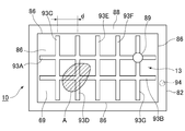
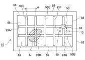
- lattice-shaped grooves 93 are provided on the surfaces 69 and 71 facing the two resin skin sheets 12 of the resin core material 13. Since the groove part 93 provided in both the surfaces 69 and 71 of the resin core material 13 is the same structure, only the groove part 93 provided in one surface 69 is demonstrated. As shown in FIG. 1, the lattice-like groove portion 93 includes a first groove portion group extending parallel to the long side of the resin core member 13 and a second groove portion group extending parallel to the short side of the resin core member 13. Composed.
- the groove portion 93 is provided with seven groove portions 93A to 93G, the groove portions 93A and 93B are parallel to the long side of the resin core material 13, and the groove portions 93C to G are the resin core material 13. Are provided in parallel with the short sides of each.
- each end does not extend to the peripheral edge portion 86 of the resin core material 13, and the groove portion 93 does not communicate with the annular space 88. In this case, it is difficult to predict in advance where and how many air pockets A are formed between the resin skin sheet 12 and the resin core material 13.
- the air accumulated therein is accumulated in the recessed portion 89 (described later) through the groove 93, and can be exhausted from the air opening hole (described later) through the groove 93.
- FIG. 1 an air reservoir A in which the closed region indicated by an oblique line having an arbitrary shape is unknown is shown.
- the interval (lattice width) between the adjacent groove portions 93 may be determined from such a viewpoint.
- the cross-sectional shape of the groove portion 93 is a flat trapezoidal shape, and the width L, the depth D, and the inclination angle ⁇ are determined as follows.
- the air accumulated in the air reservoir A is stored in the recessed portion 89 (described later) through the groove portion 93 and can be exhausted from the atmosphere opening hole (described later) through the groove portion 93. It may be determined from the viewpoint. More specifically, as will be described later, when sandwiched panels are formed, when the divided mold is clamped, the grooves 93 are determined to be formed as permanent grooves so that the grooves 93 are not lost.
- the skin material sheet 12 is made of a sheet formed of polypropylene, engineering plastics, olefin resin, or the like.
- the skin material sheet 12 constitutes the upper surface wall and the lower surface wall of the sandwich panel 10, and preferably, the outer skin material sheet 12 ⁇ / b> A and the skin material sheet 12 ⁇ / b> B are welded and integrated by pinch-off portions on the outer periphery of the sandwich panel 10. .
- a gap (not shown) is formed between the outer peripheral side wall of the sandwich panel 10 and the outer periphery of the resin core member 13, and this causes a difference in thermal shrinkage between the skin material sheet 12 after molding and the resin core member 13. Therefore, deformation of the sandwich panel 10 can be prevented.
- the skin material sheet 12 is preferably made of a resin material having a high melt tension from the viewpoint of preventing the occurrence of variations in thickness due to drawdown, neck-in, etc., while being transferred to a mold. It is preferable to use a resin material with high fluidity in order to improve the property and followability.
- a resin material with high fluidity in order to improve the property and followability.
- it is a polyolefin (for example, polypropylene, high density polyethylene) which is a homopolymer or copolymer of olefins such as ethylene, propylene, butene, isoprene pentene, methyl pentene, etc., and has an MFR (JIS K) at 230 ° C. Measured at a test temperature of 230 ° C.
- melt tension (using a melt tension tester manufactured by Toyo Seiki Co., Ltd., preheating temperature 230 ° C, extrusion speed 5.7 mm / min, diameter 2.095 mm, long A strand is extruded from an orifice having a length of 8 mm, and a tension when the strand is wound around a roller having a diameter of 50 mm at a winding speed of 100 rpm is 50 mN or more, preferably 120 mN or more.
- a hydrogenated styrene-based thermoplastic elastomer is added in a range of less than 30 wt%, preferably less than 15 wt%.
- styrene-ethylene / butylene-styrene block copolymers, styrene-ethylene / propylene-styrene block copolymers, hydrogenated styrene-butadiene rubbers and mixtures thereof are suitable as hydrogenated styrene-based thermoplastic elastomers.
- the styrene content is less than 30 wt%, preferably less than 20 wt%, and the MFR at 230 ° C. (measured at a test temperature of 230 ° C. and a test load of 2.16 kg according to JIS K-7210) is 1.0 to 10 g / 10 Minute, preferably 5.0 g / 10 min or less and 1.0 g / 10 min or more.
- the skin material sheet 12 may contain an additive as in the case of the resin core material 13, and the additive includes inorganic fillers such as silica, mica, talc, calcium carbonate, glass fiber, and carbon fiber. , Plasticizers, stabilizers, colorants, antistatic agents, flame retardants, foaming agents and the like. Specifically, silica, mica, glass fiber or the like is added in an amount of 50 wt% or less, preferably 30 to 40 wt% with respect to the molding resin.
- the decorative material sheet 14 is an object that improves appearance, decoration, and contacts with the molded product (for example, in the case of a cargo floor board, placed on the upper surface of the board). Configured for the purpose of protecting the baggage, etc.).
- a fiber skin material sheet-like skin material, a film-like skin material, or the like is applied as the material of the decorative material sheet 14.
- synthetic fibers such as polyester, polypropylene, polyamide, polyurethane, acrylic and vinylon, semi-synthetic fibers such as acetate and rayon, regenerated fibers such as viscose rayon and copper ammonia rayon, cotton, hemp, Examples thereof include natural fibers such as wool and silk, or blended fibers thereof.
- the recessed part 89 is demonstrated referring FIG. 1 and FIG. 3, the recessed part 89 is provided in the cross
- the recessed portion 89 forms an opening on each surface of the resin core material 13 to form a cylindrical through hole extending inwardly in the thickness direction, and is closed by the corresponding resin skin material sheet 12. A void to be formed is formed inside. Thereby, even if the air pocket A is formed on any surface of the resin core member 13, air can be collected from the portion into the recessed portion 89 via the groove portion 93.
- the area of the opening is set so that the surface adhesion between each surface of the resin core material 13 and the corresponding resin skin sheet 12 is sufficient. More specifically, the opening area is too large so that the bonding area is insufficient and the surface bonding is not insufficient.
- the volume of the gap is determined by the air guided to the recessed portion 89 through the groove portion 93 when the surface of the resin skin material sheet 12 corresponding to each surface of the resin core material 13 is bonded in the hollow portion. It is set to be sufficient to suppress the internal pressure rise. More specifically, it is ensured that the increase in the internal pressure in the void is not caused by the void volume being too small.
- the volume of the gap is determined by the size of the opening of the recessed portion 89 and the thickness of the resin core 13.
- the required volume of the gap is determined according to the assumed volume of the air reservoir A.
- the thickness of the resin core material 13 may be determined with respect to the maximum permissible area of the opening determined from the viewpoint of securing the surface adhesion, or the thickness of the resin core material 13 is determined in advance as a specification of the sandwich panel 10. If it is determined, the size of the opening of the recessed portion 89 is determined accordingly, and if it exceeds the maximum allowable area of the opening, for example, a plurality of recessed portions 89 are provided to ensure surface adhesion. From this point of view, they may be provided at positions sufficiently separated from each other.
- each recessed portion 89 penetrates in the thickness direction of the resin core material. You may provide in the surface of the resin-made core materials 13 in the side which provides the groove part 93, without providing. In that case, not only the case where a non-through hole is provided for the solid resin core material 13, but also one surface in a form protruding from the other surface by deforming the resin core material 13 in the thickness direction.
- each recess 89 may be provided (see FIG. 4). As shown in FIGS.
- an air opening hole 94 penetrating in the sheet thickness direction is provided at a position corresponding to the flow path of the groove portion 93 of the skin material sheet 12 ⁇ / b> B, and communicates with the groove portion 93.
- the diameter of the air opening hole 94 is smaller than the width of the groove portion 93, and the position where the air opening hole 94 is provided, particularly the positional relationship with the recessed portion 89 may be determined from the following viewpoints. That is, when the air accumulated in the air reservoir A is accumulated in the recessed portion 89 through the groove 93 and is exhausted from the atmosphere opening hole 94, a timing for providing the atmosphere opening hole 94 in the skin material sheet 12B is a split metal described later.
- the atmosphere opening hole 94 Before and after the surface welding of the resin core material 13 and the skin material sheet 12B by mold clamping, for example, when the atmosphere opening hole 94 is formed in the skin material sheet 12B with a puncture needle before welding, It is possible to prevent the air pool A from being formed at the time of welding. On the other hand, when the air opening hole 94 is formed by the same method after welding, it is formed at the time of welding. The air reservoir A will be processed afterwards. In this case, if it is before welding, the air opening hole 94 may be at an arbitrary position as long as it communicates with the groove portion 93, and if it is after welding, it may be provided at a position near the recessed portion 89.
- the peripheral portion 82 of the skin material sheets 12 ⁇ / b> A and 12 ⁇ / b> B is welded so as to sandwich the foam core material 13 using a pre-formed foam core material 13.
- the front side skin material sheet 12A and the back side skin material sheet 12B are joined to each other with the peripheral edge portions 82 to form a sealed space 84 inside.
- An annular space 88 is positively formed between the peripheral edge portion 82 and the outer peripheral edge portion 86 of the foam core material 13 in the sealed space portion 84, and two resin skin sheets of the resin core material 13 are formed.
- a lattice-like groove portion 93 that passes through the outer peripheral edge 86 of the resin core material 13 may be provided on the surfaces 69 and 71 facing each of the twelve.
- the air accumulated in the air reservoir A is accumulated in the recessed portion 89 through the groove portion 93 and exhausted from the atmosphere opening hole 94 through the groove portion 93, while being provided on the surface of the foam core member 13. Extends to the outer peripheral edge 86 of the foam core 13 and communicates with the annular space 88, so that it is formed between the foam core 13 and the skin sheets 12A and B when the mold is clamped.
- a certain air reservoir A can be dispersed in the annular space 88.
- the molding device 60 of the sandwich panel 10 includes an extrusion device 62 and a mold clamping device 64 disposed below the extrusion device 62, and the melt extruded from the extrusion device 62.
- the parison P in the state is sent to the mold clamping device 64, and the parison P in the molten state is molded by the mold clamping device 64.
- the mold clamping device 64 is also a conventionally known type like the extrusion device 62, and detailed description thereof will be omitted.
- two divided molds 73 and a sheet-like parison in which the mold 73 is melted are used.
- a mold driving device is moved between the open position and the closed position in a direction substantially perpendicular to the supply direction of P.
- the two divided molds 73 are arranged with the cavities 74 facing each other, and are arranged so that the cavities 74 are directed substantially in the vertical direction. More precisely, on the surface of each cavity 74, on the inner side of an annular pinch-off portion 76 described later, the outer shape and surface shape of the skin material sheet 12 formed on the basis of the melted sheet-like parison P Corrugated portions are provided according to the above.
- a pinch-off portion 76 is formed around the cavity 74.
- the pinch-off portion 76 is formed in an annular shape around the cavity 74 and protrudes toward the opposing mold 73. To do. As a result, when the two divided molds 73 are clamped, the tip portions of the respective pinch-off portions 76 come into contact with each other so that a parting line PL is formed at the periphery of the molten parison P.
- a pair of frame members 75 are disposed so as to be nested with the pair of molds 73 and substantially parallel to the cavity 74, and each of the pair of frame members 75 has an opening.
- the pair of frame members 75 are moved in the horizontal direction by a frame member driving device (not shown).
- a frame member driving device not shown.
- each of the pair of frame members 75 moves toward the corresponding parison P in the molten state, holds the parison P, and the tip of the pinch-off portion 76 of the corresponding mold 73 opens in the opposite direction in that state. It is possible to move until it comes into contact with the surface of the parison P.
- the mold driving device is the same as the conventional one, and the description thereof is omitted.
- the two divided molds 73 are each driven by the mold driving device, and in the open position, the two divided molds are used.
- 73 two sheet-like parisons P in a melted state can be arranged with a space between each other, and in the closed position, the pinch-off portions 76 of the two split molds 73 come into contact with each other.
- a sealed space is formed in the two divided molds 73.
- reference numeral 77 is a ventilation contact surface
- reference numeral 78 is a vacuum chamber
- reference numeral 79 is a blow pin.
- the resin core 13 is prepared in advance, and the decorative material 14 is placed in the cavity 74B.
- the molding method of the resin core material 13 it is possible to introduce foam beads into a mold and fix them by heating, as in the past, or blow molding, vacuum molding, press molding, depending on circumstances.
- the resin core material 13 may be a solid type made of a cylindrical parison or a hollow type made of a two-strip sheet as long as a groove and a recessed portion 89 communicating with the groove are formed on each surface.
- positioning timing of the resin-made core material 13 may be any time as long as it is after mold opening to mold clamping.
- thermoplastic resin sheets P1 and P2 are extruded vertically downward from corresponding die slits, and two continuous sheet-like thermoplastic resin sheets P1 and P2 are correspondingly pinched off. It is supplied between the two split molds 73 in a form protruding from the part 76.
- the mold 75A of the split mold 73A is moved toward the thermoplastic resin sheet P1 with respect to the split mold 73A and brought into contact with the side surface 83 of the thermoplastic resin sheet P1. Thereby, a sealed space is formed by the side surface 83 of the thermoplastic resin sheet P1, the inner peripheral surface of the mold 75A, and the cavity 73A.
- thermoplastic resin sheet P1 is adsorbed to the cavity 74A, whereby the thermoplastic resin sheet P1 is sucked into the cavity 74A. It is shaped into a shape along the surface.
- the resin core material 13 is disposed between the two thermoplastic resin sheets P1 and 2 in parallel with both sheets, and the surface of the resin core material 13 is made to face the inner surface of the thermoplastic resin sheet P1. And press to fix. At this time, since the surface on the opposite side of the resin core 13 is open, air between the resin core 13 and the inner surface of the thermoplastic resin sheet P1 is passed through the lattice-shaped grooves 93 and the recesses 89. It is possible to escape through. Next, an air opening hole is penetrated in the thickness direction of the sheet, for example, by a puncture needle at a position corresponding to the flow path of the groove portion 93 of the thermoplastic resin sheet P1.
- the molds 73A and 73B are moved toward each other until the pinch-off portions 76A and B come into contact with each other, and the molds are clamped. More specifically, the pair of split molds 73 are moved to the mold clamping position, and the inner surfaces of the two thermoplastic resin sheets P1 and 2 are welded along the pinch-off portions 76 of the pair of molds 73.
- the peripheral portions of the two thermoplastic resin sheets P1 and P2 are integrated.
- the air in the air reservoir A formed somewhere between the inner surface of the resin skin sheet P2 and the surface 69 of the resin core material 13 Is stored in the recess 89 through the groove 93 and exhausted from the air opening hole 94 through the groove 93, while the resin is applied to the inner surfaces of the two thermoplastic resin sheets P1 and P2.
- the core material 13 can be integrated by welding.
- the decorative material 14 is also welded to the thermoplastic resin sheet P2. Note that the effect of air venting when the divided mold 73 is clamped is the same between the surface 71 of the resin core 13 and the resin skin sheet P1.
- the extruded thermoplastic resin sheet P may be formed into a sheet shape by crushing the molten cylindrical parison, or at least two locations during extrusion by extruding the molten cylindrical parison.
- the cylindrical parison may be cut along the extrusion direction to form two sheets.
- the two split molds 73 are opened, the completed resin sandwich panel 10 is separated from the cavity 74, and burrs formed around the parting line PL are removed. Thus, the molding of the resin sandwich panel 10 is completed.
- thermoplastic resin sheets P1 and P2 in a molten state, and shape the extruded thermoplastic resin sheets P1 and P2 into a predetermined shape using a mold 73.
- the groove portion 93 stretched over the entire surface of each of the surfaces of the resin core material 13 facing the two resin skin sheets 12, and Since the concave portion 89 communicating with the groove portion 93 is provided, when the surface of the resin core material 13 on the groove portion 93 side and the resin skin material sheet 12 opposite to the surface are bonded to each other, between them Even if an air pool is unexpectedly formed, the air accumulated in the air pool can be accumulated in the recessed portion 89 through the groove 93 and exhausted from the atmosphere opening hole 94 through the groove 93. Yes, the groove portion 93 functions as an air vent.
- the sandwich panel 10 made of resin even if it causes molding defects due to air accumulation or is not defective, it is made of resin. There is no risk of insufficient welding between the material 13 and the resin skin sheet, causing insufficient rigidity of the resin sandwich panel 10 as a whole, or the area of the air pocket is expanded and partially swells, It is possible to provide a resin sandwich panel 10 that can ensure the necessary rigidity without causing molding defects while maintaining the aesthetic appearance of the appearance without impairing the aesthetic appearance of the sandwich panel 10.
- the air release hole 94 is formed by penetrating the stab needle in the thickness direction with respect to the molten resin sheet constituting the skin material sheet 12, but in the second embodiment to the fourth embodiment, the skin material sheet 12 has On the other hand, the positions where the air opening holes 94 are provided are different, and due to this, the form of the groove 93 or the surface form of the core member 13 is different.
- the characteristic part of this embodiment is the aspect of the groove part 93 according to the point which provided the air
- FIG. More specifically, firstly, the surface of the skin material sheet 12 is penetrated in the thickness direction by the stab needle to form the air opening hole 94 so that the tip of the stab needle does not reach the surface of the resin core material 13. Since it is technically difficult to control the positioning of the puncture needle, an evacuation space for the puncture needle is provided in a portion corresponding to the air opening hole 94 of the resin core member 13, and in this case, as shown in FIG. As described above, the recessed portion 89 is used as a space for avoiding the puncture needle.
- the size of the opening formed by the recessed portion 89 is sufficient for surface bonding when the resin core material 13 and the corresponding skin material sheet 12 are welded to each other.
- the volume of the gap formed by the recessed portion 89 is determined from the viewpoint of suppressing an increase in internal pressure in the gap due to the air guided through the groove 93, but the opening area required for the air opening hole 94 is determined. Since it is sufficient that the air gap and the atmosphere are ventilated, the opening area of the air release hole 94 is determined so that the recessed portion 89 can be effectively used as a space for avoiding the puncture needle, and the puncture needle 94 Decide the thickness.
- the groove portion 93 is crushed and further flattened, and the back side skin
- the material sheet 12B is bonded to the bottom surface 92 of the groove portion 93, thereby ensuring sufficient bonding between the back-side skin material sheet 12B and the resin core material 13.
- the groove portion 93 is further flattened and the resin skin material sheet P ⁇ b> 2 is joined to the bottom surface 92 of the groove portion 90, thereby the resin skin material.
- any one of the lattice-like grooves 93 communicates with the air reservoir A.
- air can be vented from the air reservoir A through the groove portion 93 through the air release hole 94. More specifically, when the pressure of the sealed space in the mold increases when the divided molds are clamped, the air accumulated in the air reservoir A can escape from the air release hole 94 to the outside air.
- the density of the grid-like grooves 93 on the surface 69 is increased so that the air accumulated there can be removed through the air opening hole 94, and the air pocket formed unexpectedly. It is the same as that of the first embodiment in that the groove 93 needs to communicate with A. In addition, about the formation method of the sandwich panel 10 of this embodiment, it is the same as that of 1st Embodiment.
- the characteristic part of the present embodiment is that the air opening hole 94 is not provided in the portion of the skin material sheet 12 corresponding to the surface of the core material 13, and between the core material 13 and the skin material sheet 12.
- An air opening hole 94 is provided in a portion of the annular space 88 formed in the above, and a groove portion 93 is provided so as to pass through the outer peripheral edge portion 86 of the core member 13 and communicated with the annular space 88 accordingly.
- the annular space 88 is itself
- the volume is larger than the air reservoir A on the resin core 13, so the annular space 88 that must be passively formed from the viewpoint of molding is actively utilized.
- the air accumulated on the resin core 13 is exhausted.
- the two resin skin sheets 12 are formed by forming the annular space 88 around the resin core material 13 by joining the peripheral edges thereof to each other, thereby providing two resin skin sheets.
- 12 is provided on at least one surface of the resin core member 13 opposed to the outer periphery of the resin core member 13 with a lattice-like groove portion 93 extending to the outer edge of the resin core member 13, whereby the lattice-like groove portion 93 communicates with the annular space 88. Therefore, when the surface of the resin core material 13 on the grid-like groove 93 side and the resin skin material sheet 12 facing the surface are bonded to each other, an air pocket is unexpectedly formed between them.
- the air accumulated in the air reservoir can be dispersed into the recessed portion 89 and the annular space 88 through the lattice-like groove portion 93, and the annular space 88 itself becomes the air reservoir A, Resin core Compared to the air trap A on the upper ridge 13, the problem of weldability and the appearance problem due to swelling are small, but on the other hand, the volume is larger than that of the air reservoir A on the resin core 13. For example, when the resin sandwich panel 10 is molded, the resin core material 13 and the resin skin sheet 12 may be formed even if the molding is caused by the air reservoir A or not.
- Resin sandwich panel 1 that can ensure the required rigidity without causing molding defects while maintaining the appearance of the appearance without impairing the appearance. It is possible to provide zero.
- the characteristic part of this embodiment is the same as that of the second embodiment in that the air opening hole 94 is provided in the part of the skin material sheet 12 corresponding to the surface of the core material 13, but in the second embodiment, In accordance with the position where the concave portion 89 is provided on the surface of the core material 13, the air opening hole 94 is provided, and thus the concave portion 89 itself is used as an avoidance space for the puncture needle.
- the air opening hole 94 is provided at a position different from the position at which the recessed portion 89 is provided on the surface of the core material 13, thereby providing a puncture needle avoidance space on the surface of the core material 13 separately from the recessed portion 89. .
- an air opening hole 94 is provided in a portion of the skin material sheet 12 corresponding to the intersection of the groove 93, and accordingly, a puncture needle avoidance space 50 is provided at the intersection of the groove 93.
- an avoidance space 50 which is a space large enough not to touch the puncture needle, is located at a position corresponding to the air opening hole 94 of the skin material sheet 12. It is provided over the direction.
- the shape of the avoidance space 50 is a columnar shape, and the axis of the column is provided so as to be orthogonal to the back surface skin sheet 12B. May be determined according to the shape of the puncture needle, and when the tip of the puncture needle reaches the surface of the resin core material 13, there is a hole in the surface of the resin core material 13, which is easily damaged. What is necessary is just to determine from the viewpoint of preventing this from happening.
- the groove 93 is provided only on one surface of the resin core material 13, it is only necessary to provide the air release hole 94 in the skin material sheet 12 corresponding to the one surface.
- 50 it is not necessary to penetrate in the thickness direction of the resin core member 13, and it may be provided as a recess opening on one surface.
- the characteristic part of this embodiment is in the form of the groove portion 93, and the point that the groove portion 93 is a permanent groove is the same as that of the first embodiment.
- the groove portion 93 has a lattice shape.
- the single curved long groove 100 is provided in a meandering manner so as to extend over the entire surface of the resin core material 13.
- the recessed portion 89 is provided at the intersecting portion of the groove portion 93.
- the recessed portion 89 since the intersecting portion of the groove portion 93 does not exist, the recessed portion 89 has the curved long groove 100. Is provided so as to communicate with the curved long groove 100.
- the groove portion 93 is provided over the entire surface of the resin core member 13, various forms of the groove portion 93 are possible.
- a plurality of annular grooves 101 having a permanent groove shape are provided.
- the annular grooves 101 adjacent to each other may communicate with each other via the communication path 103.
- the recessed portion 89 is provided in the middle of one of the nested annular grooves 101. That's fine.
- a concave is formed on the surface of the core material 13 in order to remove air from an unexpected air pocket A formed between the surface of the resin core material 13 and the skin sheet 12A, B during molding.
- the characteristic part of this embodiment exists in the aspect of the recessed part 89 and the groove part 93.
- FIG. As shown in FIGS. 14 and 15, the recessed portion 89 is a cylindrical through hole penetrating in the thickness direction of the resin core material 13, and the resin sheet corresponding to the skin material sheet 12 ⁇ / b> A is formed during molding.
- the diameter thereof is stabbed.
- the tip of the needle 202 penetrates in the thickness direction of the skin material sheet 12A and is set to be larger than at least the outer diameter of the puncture needle 202 so as not to come into contact with the puncture needle 202 so as to fit in the middle of the concave portion 89 in the thickness direction. .
- the piercing needle 202 has a hollow portion 203 extending to the tip, and when the mold 73 is clamped during molding, the resin core material 13 and the resin sheet facing the surface are welded to each other, and the inside of the mold 73 When the stab needle 202 is stabbed immediately after mold clamping, the air accumulated in the recess 89 is exhausted through the stab needle 202 or the stab needle 202 is withdrawn. It is possible to exhaust air through an air opening hole formed in the communicating skin material sheet 12A.
- the groove part 93 Although the point connected to the annular space 88 formed between the peripheral part 82 of a pair of skin material sheets 12 and the peripheral part 86 of the resin core material 13 is common to 1st Embodiment. , Formed as a permanent groove. More specifically, the groove portion 93 has a lattice shape so as to be stretched over the entire surface of each surface of the resin core member 13, and a recessed portion 89 is provided on the lattice point.
- the depth and width of the groove portion 93 and the pitch between the adjacent groove portions 93 are determined according to the application of the sandwich panel product 10, and particularly when a product overview is required, the width is narrow and the depth is shallow. The width is preferably 4 mm or less and the depth is 1 mm or less.
- the groove portion 93 disappears, so that there is no effect of driving air into the recessed portion 89 via the groove portion 93, but the groove portion 93 itself is a permanent groove. As with the recessed portion 89, it functions as an active air reservoir.
- the needle 202 serves as a mark when the outer surface of the resin sheet is pierced toward the resin core 13. According to the above configuration, during molding, air is released from the unexpected air reservoir A to the recessed portion 89 via the permanent groove and the annular space 88 or directly to the recessed portion 89 via the permanent groove. It is possible to pierce the piercing needle 202 from the outer surface of the portion corresponding to the recessed portion 89 of the resin sheet corresponding to 12A and exhaust the air through the piercing needle 202.
- a recess is formed in the surface of the resin core material 13.
- the characteristic part of this embodiment exists in the aspect of the recessed part 89 and the groove part 93.
- the recessed portion 89 is a substantially frustoconical non-through hole extending in the thickness direction of the resin core material 13 and is provided in the vicinity of the peripheral edge portion 86 of the resin core material 13.
- the stab needle 202 is stabbed from the outer surface of the portion corresponding to the recessed portion 89 of the resin sheet corresponding to the skin material sheet 12A toward the resin core member 13, and the air accumulated in the recessed portion 89 is pierced by the puncture needle 202.
- the diameter of the puncture needle 202 does not come into contact with the puncture needle 202 so that the tip of the puncture needle 202 penetrates in the thickness direction of the skin material sheet 12A and fits in the middle of the thickness direction of the recessed portion 89. And at least larger than the outer diameter of the puncture needle 202.
- the piercing needle 202 has a hollow portion 203 extending to the tip, and when the mold 73 is clamped during molding, the resin core material 13 and the resin sheet facing the surface are welded to each other, and the inside of the mold 73 When the stab needle 202 is stabbed immediately after mold clamping, the air accumulated in the recess 89 is exhausted through the stab needle 202 or the stab needle 202 is withdrawn. It is possible to exhaust air through an air opening hole formed in the communicating skin material sheet 12A.
- the groove part 93 although the point connected to the annular space 88 formed between the peripheral part 82 of a pair of skin material sheets 12 and the peripheral part 86 of the resin core material 13 is common to 1st Embodiment. , Formed as a permanent groove. More specifically, the groove 93 is provided on one surface of the resin core 13 as a single groove that communicates the recessed portion 89 provided in the vicinity of the peripheral edge 86 of the resin core 13 and the annular space 88. It is done.
- the depth and width of the groove 93 are determined in accordance with the use of the sandwich panel product 10, and particularly when a product overview is required, the width is narrow and the depth is shallow, for example, the width is 4 mm or less, the depth Is preferably 1 mm or less.
- the annular space 88 is used as an active air reservoir, and the air accumulated in the annular space 88 is released to the recessed portion 89 through the permanent groove, and the resin corresponding to the skin sheet 12A. It is possible to pierce the piercing needle 202 from the outer surface of the portion corresponding to the recessed portion 89 of the manufactured sheet, and to exhaust the air through the piercing needle 202.
- the sandwich panel 10 is a structural member resistant to bending rigidity or bending buckling for automobiles, aircrafts, vehicles / ships, building materials, housings for various electrical equipment, bed floors, sports / leisure. Can be suitably used. In particular, it can improve fuel efficiency from the viewpoint of weight reduction as a structural member for automobiles, specifically, interior panels such as cargo floor boards, deck boards, rear parcel shelves, roof panels, door trims, and other doors. It contributes to weight reduction as a structural member such as an inner panel, platform, hardtop, sunroof, bonnet, bumper, floor spacer, devia pad, etc.
- the shape of the sandwich panel 10 can be appropriately determined according to the purpose of the product. .
- the sandwich panel 10 will be described below by taking as an example a case where the sandwich panel 10 is used for a cargo floor lid of an automobile that is required to be lightweight and highly rigid.
- such a sandwich panel 10 includes a front surface skin sheet 12A, a back surface skin sheet 12B, and a foaming foam core interposed between both skin sheets 12A and 12B.
- the sandwich panel 10 includes a decorative material sheet 14, a front surface skin material sheet 12A, foamed material 13 and a decorative material sheet 14 bonded to the outer surface of the front surface skin material sheet 12A. It is a laminated structure of the core material 13 and the back surface skin sheet 12B.
- the front side skin material sheet 12 ⁇ / b> A and the back side skin material sheet 12 ⁇ / b> B form a sealed space portion 84 inside by joining the peripheral edge portions 82 to each other.
- An annular space 88 is formed between the peripheral edge 82 and the outer peripheral edge 86 of the foam core 13 in the sealed space 84.
- the annular space 88 is formed on the sandwich panel 10 formed by the peripheral edge portion 82 when the molten thermoplastic resin sheet, which is the material of the front side skin sheet 12A and the back side skin sheet 12B, is formed.
- the peripheral wall is passively provided from the viewpoint of adhering to the foam core 13 and causing no molding failure.
- the sandwich panel 10 is molded using the preformed foam core material 13 so that the peripheral edge portions 82 of the skin material sheets 12A and 12B are welded so as to sandwich the foam core material 13 therebetween.
- a groove provided on the surface of the foam core member 13 to be described later extends to the outer peripheral edge 86 of the foam core member 13 and communicates with the annular space 88.
- lattice-shaped grooves 93 extending to the outer peripheral edge 91 of the resin core material 13 are formed on the surfaces 69 and 71 of the resin core material 13 facing each of the two resin skin sheets 12. Is provided. Since the groove part 93 provided in both the surfaces 69 and 71 of the resin core material 13 is the same structure, only the groove part 93 provided in one surface 69 is demonstrated.
- the lattice-like groove 93 is configured by a first groove group extending parallel to the long side of the resin core material 13 and a second groove group extending parallel to the short side of the resin core material 13, and the first groove group. And each groove part of the 2nd groove part group is provided so that it may come out to the outer periphery 86 of resin core material 13.
- the groove portion 93 is provided with seven groove portions 93A to 93G, the groove portions 93A and 93B are parallel to the long side of the resin core material 13, and the groove portions 93C to G are the resin core material 13. These are provided in parallel with the short sides of the resin cores, and both are arranged so as to come out to the outer peripheral edge 86 of the resin core material 13. In this case, it is difficult to predict in advance where and how many air pockets A are formed between the resin skin sheet 12 and the resin core material 13. In order to be able to disperse the air accumulated therein to the annular space 88, the density of the lattice-like grooves 93 is increased so that the grooves 93 are formed in the unexpectedly formed air reservoir A. It is necessary to communicate. In FIG. 19, an air reservoir A in which the closed region indicated by an oblique line having an arbitrary shape is unknown is shown. The interval (lattice width) between the adjacent groove portions 93 may be determined from such a viewpoint.
- the cross-sectional shape of the groove portion 93 is a flat trapezoidal shape, and the width L, the depth D, and the inclination angle ⁇ are determined as follows. What is necessary is just to determine from the viewpoint of dispersing the air accumulated in the air reservoir A through the groove portion 93 when clamping the mold. In particular, for the depth D and the inclination angle ⁇ , as shown in FIG. 20B, when the divided mold is clamped, the groove 93 is crushed and further flattened, as will be described later. It is also necessary to determine from the viewpoint that the back surface skin sheet 12B is bonded to the bottom surface 92 of the groove portion 93, thereby ensuring sufficient bonding between the back surface sheet 12B and the resin core material 13.
- the molding device 60 of the resin sandwich panel 10 includes an extrusion device 62 and a mold clamping device 64 disposed below the extrusion device 62, and is in a molten state extruded from the extrusion device 62.
- the thermoplastic resin sheet P is sent to the mold clamping device 64, and the mold clamping device 64 molds the molten thermoplastic resin sheet P.
- the extruding device 62 is a conventionally known type, and detailed description thereof is omitted. However, a cylinder 66 provided with a hopper 65, a screw (not shown) provided in the cylinder 66, and a screw are connected to the screw. A hydraulic motor 68, an accumulator 70 communicating with the inside of the cylinder 66, and a plunger 72 provided in the accumulator 70, and resin pellets introduced from the hopper 65 are screwed by the hydraulic motor 68 in the cylinder 66. The molten resin is melted and kneaded by the rotation of the resin, and the molten resin is transferred to the accumulator chamber and stored in a certain amount.
- the plunger 72 is driven to feed the molten resin toward the T die 71 and continuously through the die slit (not shown).
- a sheet-like thermoplastic resin sheet P is extruded and spaced apart. While being pinched by the pair of rollers 79, it is sent downward and is suspended between the split molds 73. Thereby, the sheet-like thermoplastic resin sheet P is disposed between the split molds 73 without being wrinkled or loosened.
- the extrusion capability of the extrusion device 62 is appropriately selected from the viewpoints of the size of the front side skin material sheet 12A and the back side skin material sheet 12B to be molded, and the prevention of the drawdown of the thermoplastic resin sheet P. More specifically, from a practical viewpoint, the extrusion rate of the resin from the die slit is several hundred kg / hour or more, more preferably 700 kg / hour or more. Further, from the viewpoint of preventing the drawdown of the thermoplastic resin sheet P, the extrusion process of the thermoplastic resin sheet P is preferably as short as possible and generally depends on the type of resin and the MFR value. Should be completed within 40 seconds, more preferably within 30 seconds. For this reason, the extrusion area per unit area and unit time of the thermoplastic resin from the die slit is 50 kg / hour cm 2 or more, more preferably 60 kg / hour cm 2 or more.
- the die slit 75 is arranged vertically downward, and the thermoplastic resin sheet P extruded from the die slit 75 is sent vertically downward in a form that hangs down from the die slit 75 as it is.
- the width of the die slit variable it is possible to change the thickness of the continuous sheet-like thermoplastic resin sheet P.
- the mold clamping device 64 is also a conventionally known type like the extrusion device 62, and detailed description thereof will be omitted.
- two divided molds 73 and a sheet-like heat in which the mold 73 is melted are used.
- a mold driving device that moves between an open position and a closed position in a direction substantially orthogonal to the supply direction of the plastic resin sheet P;
- the two divided molds 73 are arranged with the cavities 74 facing each other, and the cavities 74 are arranged so as to face substantially vertically.
- the surface of each cavity 74 is in accordance with the outer shape and the surface shape of the front side skin material sheet 12A and the back side skin material sheet 12B which are molded based on the molten sheet-like thermoplastic resin sheet P. An uneven portion is provided.
- a pinch-off portion 76 is formed around the cavity 74.
- the pinch-off portion 76 is formed in an annular shape around the cavity 74 and protrudes toward the opposing mold 73. To do.
- the tip portions of the respective pinch-off portions 76 come into contact with each other so that the parting line PL is formed at the periphery of the molten thermoplastic resin sheet P. I have to.
- the mold 81A is slidably fitted on the outer periphery of the split mold 73A, and the mold 81A is movable relative to the mold 73A by a mold moving device (not shown). More specifically, the mold 81 ⁇ / b> A protrudes toward the mold 73 ⁇ / b> B with respect to the mold 73 ⁇ / b> A, so that the mold 81 ⁇ / b> A can contact one side surface 83 of the thermoplastic resin sheet P ⁇ b> 1 disposed between the molds 73. It is.
- a vacuum suction chamber 85 is provided inside the split mold 73 ⁇ / b> A, and the vacuum suction chamber 85 communicates with the cavity 74 ⁇ / b> A via the suction hole 87.
- the sheet P1 made of the thermoplastic resin is adsorbed toward the cavity 74A and is shaped into a shape along the outer surface of the cavity 74A.
- the mold driving device is the same as the conventional one, and the description thereof is omitted.
- the two divided molds 73 are each driven by the mold driving device, and in the open position, the two divided molds are used.
- two continuous sheet-like thermoplastic resin sheets P1 and 2 in a molten state can be arranged with a space between each other, and in one closed position, the pinch-off portions of the two split molds 73 76 abuts and the annular pinch-off portions 76 abut each other so that a sealed space is formed in the two split molds 73.
- the closed position is the position of the center line of the two continuous sheet-like thermoplastic resin sheets P1 and 2 in the molten state. It is driven by the mold driving device so as to move toward the position.
- the foam core material 13 is prepared in advance, and the decorative material 14 is disposed in the cavity 74B.
- the foamed beads may be introduced into the mold and fused and fixed by heating as in the prior art, or blow molding, vacuum molding, press molding, or injection depending on the case.
- the foamed core material 13 may be a solid type made of a cylindrical parison or a hollow type made of a two-sheet.
- positioning timing of the foaming core material 13 may be any time as long as it is after mold opening to mold clamping.
- thermoplastic resin sheets P1 and P2 in the molten state are extruded vertically downward from the corresponding die slits 75 to correspond to the two continuous sheet-like thermoplastic resin sheets P1 and P2.
- the sheet is supplied between the two divided molds 73 so as to protrude from the pinch-off portion 76.
- the mold 81A of the split mold 73A is moved toward the thermoplastic resin sheet P1 with respect to the split mold 73A, so that it contacts the side surface 83 of the thermoplastic resin sheet P1. Make contact. As a result, a sealed space 84 is formed by the side surface 83 of the thermoplastic resin sheet P1, the inner peripheral surface 102 of the mold 81A, and the cavity 73A.
- thermoplastic resin sheet P1 is adsorbed to the cavity 74A, thereby The thermoplastic resin sheet P1 is shaped into a shape along the surface of the cavity 74A.
- the foam core material 13 is disposed between the two thermoplastic resin sheets P1 and 2 in parallel with both sheets, and the surface of the foam core material 13 is pressed against the inner surface of the thermoplastic resin sheet P1. And fix it by welding. At this time, the air between the foamed core material 13 and the inner surface of the thermoplastic resin sheet P1 can be removed through the lattice-shaped grooves 93.
- thermoplastic resin sheet P1 in a state in which the thermoplastic resin sheet P1 is sucked and held in a state where the mold 81 that is in contact with the outer surface 83 of the thermoplastic resin sheet P1 is held as it is, The molds 73A and 73B are moved toward each other until the pinch-off portions 76A and B come into contact with each other, and the molds are clamped. More specifically, the pair of split molds 73 are moved to the mold clamping position, and the inner surfaces of the two thermoplastic resin sheets P1, 2 are welded along the pinch-off portions of the pair of molds 73. Thus, the peripheral portions of the two thermoplastic resin sheets P1 and P2 are integrated.
- the air in the air reservoir A formed somewhere between the inner surface of the resin skin sheet P2 and the surface 69 of the resin core material 13 is latticed.
- the resin core material 13 is dispersed with respect to the inner surfaces of the two thermoplastic resin sheets P1 and P2 while being dispersed in the annular space 88 via the peripheral groove portion 86 and the peripheral edge portion 86 of the resin core material 13. It is possible to integrate them by welding.
- the decorative material 14 is also welded to the thermoplastic resin sheet P2. In this case, by crushing the groove 93 of the resin core material 13 (see FIG. 20B), the groove 93 is further flattened and the resin skin material sheet P2 is bonded to the bottom surface 92 of the groove 90.
- the extruded thermoplastic resin sheet P may be formed into a sheet by crushing the molten cylindrical parison, or at least two locations during extrusion by extruding the molten cylindrical parison.
- the cylindrical parison may be cut along the extrusion direction to form two sheets.
- the two split molds 73 are opened, the completed resin sandwich panel 10 is separated from the cavity 74, and burrs formed around the parting line PL are removed. Thus, the molding of the resin sandwich panel 10 is completed.
- thermoplastic resin sheets P1 and P2 in a molten state, and shape the extruded thermoplastic resin sheets P1 and P2 into a predetermined shape using a mold 73.
- the annular space 88 is as itself. Although it becomes an air pool, there is no problem of the weldability between the resin core material 13 and both skin sheets 12 as compared with the air pool formed on the resin core material 13, and there is a problem in appearance due to swelling.
- the annular space 88 since the volume is larger than the air reservoir on the resin core 13, the annular space 88 that must be passively formed from the viewpoint of molding is actively utilized to make the resin The air accumulated on the core material 13 is dispersed.
- the two resin skin sheets 12 are formed by forming the annular space 88 around the resin core material 13 by joining the peripheral edges thereof to each other, thereby providing two resin skin sheets.
- 12 is provided on at least one surface of the resin core member 13 opposed to the outer periphery of the resin core member 13 with a lattice-like groove portion 93 that passes through the outer edge of the resin core member 13. Therefore, when the surface of the resin core material 13 on the grid-like groove 93 side and the resin skin material sheet 12 facing the surface are bonded to each other, an air pocket is unexpectedly formed between them.
- the air accumulated in the air reservoir can be dispersed into the annular space 88 through the lattice-like groove 93, and the annular space 88 itself becomes an air reservoir, but on the resin core 13 Air pocket Compared to the problem of weldability, the problem of appearance due to swelling is small, but since the volume is large compared to the air reservoir on the resin core material, the lattice-like groove portion functions as an air vent, for example, When molding the sandwich panel 10 made of resin, even if it causes poor molding due to the air trap A, or if it is not defective molding, insufficient welding between the resin core material 13 and the resin skin sheet 12 occurs.
- the characteristic part of the present embodiment is that the atmosphere opening hole 90 is provided in the resin skin sheet 12, and the groove 93 according to the feature is provided. More specifically, as shown in FIG. 26, the air opening hole 90 provided in the resin skin material sheet 12 is an adhesion portion between the resin skin material sheet 12 and the resin core material 13, that is, the resin core material 13. This is a portion of the resin skin sheet 12 that opposes the surface, and is a position corresponding to the annular space 88, and is provided with two air opening holes 90.
- the lattice-like groove portion 93 extends to the outer peripheral edge 86 of the resin core member 13 and comes out to the outer peripheral edge 86, whereas in this embodiment, As shown in FIG. 9, the point that the groove portions 93 are provided in a lattice shape is common, but the lattice-like groove portions 93 extend to the outer peripheral edge 86 of the resin core 13 and come out to the outer peripheral edge 86. This is a point that extends to the inner peripheral edge 97 of the resin core material 13 and comes out to the inner peripheral edge 97.
- the resin core material 13 penetrates through the thickness of the resin core material 13 so as to communicate with the air open hole 90 at a position corresponding to the air open hole 90.
- the through hole 99 is provided, the groove 93 extends to the inner peripheral edge 97 of the through hole 99, and comes out to the inner peripheral edge 97.
- the shape and size of the through hole 99 are arbitrary as long as they communicate with the atmosphere opening hole 90. From the viewpoint of securing the rigidity of the sandwich panel, the shape is preferably cylindrical and the size is preferably as small as possible.
- any one of the lattice-like grooves 93 communicates with the air reservoir A.
- the accumulated air is dispersed in the annular space 88.
- the air is vented from the air reservoir A through the air opening hole 90 through the groove 93. It is possible.
- the air accumulated in the air reservoir A passes through the through holes 99 through the grooves 93B or 93C, A, Furthermore, it is possible to escape from the atmosphere opening hole 90 communicating with the through hole 99 or the atmosphere opening hole 90 provided at a position corresponding to the annular space 88 to the outside air.
- the density of the grid-like grooves 93 on the surface 69 is increased so that the air accumulated there can be extracted through the air opening hole 90, and the air pocket formed unexpectedly. It is the same as that of the eighth embodiment in that the groove 93 needs to communicate with A.
- the sandwich panel forming method of the present embodiment is the same as that of the eighth embodiment.
- a recess 89 is further provided at the intersection of the groove 93. Similar to the first embodiment, the recessed portion 89 is provided at the intersection of the groove portions 93 and is disposed so as to communicate with the vertical and horizontal groove portions 93. As in the first embodiment, the recessed portion 89 is formed with a cylindrical through-hole formed on each surface of the resin core member 13 so as to form an opening and extend inward in the thickness direction. A gap closed by the resin skin sheet 12 is formed inside. As a result, regardless of the surface of the resin core material 13 where the air pool A is formed, the air accumulated in the air pool A is dispersed in the annular space 88 through the lattice-shaped grooves 93. It is possible to collect air in the recess 89 through the groove 93.
- the lattice-shaped groove portion 93 is provided with a single curved long groove or a plurality of annular grooves in a nested manner based on the first embodiment.
- the grid-like groove portion 93 may be provided in a single curved long groove or a plurality of annular grooves in a nested manner in any of the second to fourth embodiments.
- the thermoplastic resin sheets P1 and P2 in a molten state extruded from the extrusion slit are directly formed.
- the present invention is not limited thereto, and one and / or the other thermoplastic resin sheet P1 is used. , P2 may be preformed in advance and reheated into a molten state.
- the present invention is not limited thereto, and the cross-shaped groove portion is provided as long as the air accumulated in the air reservoir A can be extracted to the outside air.
- a groove part may be sufficient.
- the thermoplastic resin sheets P1 and P2 in a molten state extruded from the extrusion slit are directly formed.
- the present invention is not limited thereto, and one and / or the other thermoplastic resin sheet is used. P1 and P2 may be preformed in advance and reheated into a molten state.
- FIG. 1 is a plan view of a resin sandwich panel 10 according to a first embodiment of the present invention.
- FIG. 3 is a partial cross-sectional view taken along line BB in FIG.
- FIG. 2 is a partial cross-sectional view taken along line AA in FIG. It is a figure similar to FIG. 2 of the modification of the resin sandwich panel 10 which concerns on 1st Embodiment of this invention.
- It is a schematic fragmentary sectional view which shows the condition which has arrange
- FIG. 11 is a partial cross-sectional view taken along line CC in FIG. 10. It is a top view of resin-made sandwich panel 10 concerning a 5th embodiment of the present invention. It is a top view of the resin-made sandwich panels 10 which concern on the modification of 5th Embodiment of this invention.
- FIG. 20 is a partial cross-sectional view taken along line AA of FIG.
- FIG. 3 is a schematic partial cross-sectional view showing a state in which a thermoplastic resin sheet P1 is shaped in the molding process of the resin sandwich panel 10 according to the embodiment of the present invention.
- FIG. 3 is a schematic partial cross-sectional view showing a state in which a resin core material is disposed between thermoplastic resin sheets P1 and P2 in the molding process of the resin sandwich panel 10 according to the embodiment of the present invention.
- FIG. 20 is a plan view of a resin sandwich panel 10 according to a ninth embodiment of the present invention, similar to FIG.
- FIG. 27 is a partial cross-sectional view taken along line BB in FIG. 26.
- FIG. 20 is a plan view of a resin sandwich panel 10 according to a tenth embodiment of the present invention, similar to FIG.
Landscapes
- Engineering & Computer Science (AREA)
- Mechanical Engineering (AREA)
- Laminated Bodies (AREA)
- Blow-Moulding Or Thermoforming Of Plastics Or The Like (AREA)
Abstract
Priority Applications (4)
| Application Number | Priority Date | Filing Date | Title |
|---|---|---|---|
| CN201580031734.9A CN106457742B (zh) | 2014-06-19 | 2015-05-30 | 树脂制夹芯板及树脂制夹芯板的制造方法 |
| EP15809252.8A EP3159154B1 (fr) | 2014-06-19 | 2015-05-30 | Panneau sandwich en résine et procédé de fabrication de panneau sandwich en résine |
| KR1020167035113A KR101933393B1 (ko) | 2014-06-19 | 2015-05-30 | 수지제 샌드위치 패널 및 수지제 샌드위치 패널의 제조 방법 |
| US15/319,302 US10232584B2 (en) | 2014-06-19 | 2015-05-30 | Resin sandwich panel, and method for manufacturing resin sandwich panel |
Applications Claiming Priority (2)
| Application Number | Priority Date | Filing Date | Title |
|---|---|---|---|
| JP2014125999A JP6489399B2 (ja) | 2014-06-19 | 2014-06-19 | 樹脂製サンドイッチパネル |
| JP2014-125999 | 2014-06-19 |
Publications (1)
| Publication Number | Publication Date |
|---|---|
| WO2015194349A1 true WO2015194349A1 (fr) | 2015-12-23 |
Family
ID=54935340
Family Applications (1)
| Application Number | Title | Priority Date | Filing Date |
|---|---|---|---|
| PCT/JP2015/065699 Ceased WO2015194349A1 (fr) | 2014-06-19 | 2015-05-30 | Panneau sandwich en résine et procédé de fabrication de panneau sandwich en résine |
Country Status (6)
| Country | Link |
|---|---|
| US (1) | US10232584B2 (fr) |
| EP (1) | EP3159154B1 (fr) |
| JP (1) | JP6489399B2 (fr) |
| KR (1) | KR101933393B1 (fr) |
| CN (1) | CN106457742B (fr) |
| WO (1) | WO2015194349A1 (fr) |
Cited By (5)
| Publication number | Priority date | Publication date | Assignee | Title |
|---|---|---|---|---|
| JP2016141034A (ja) * | 2015-02-02 | 2016-08-08 | キョーラク株式会社 | 樹脂製パネル |
| WO2017115640A1 (fr) * | 2015-12-28 | 2017-07-06 | 東レ株式会社 | Structure en couches, objet moulé et procédés de production associés |
| WO2019167817A1 (fr) * | 2018-02-28 | 2019-09-06 | キョーラク株式会社 | Panneau de résine et procédé pour le fabriquer |
| CN112318899A (zh) * | 2020-09-25 | 2021-02-05 | 北京机科国创轻量化科学研究院有限公司 | 一种生产增强型热塑性复合材料的生产线以及加工方法 |
| CN114845858A (zh) * | 2019-12-16 | 2022-08-02 | 光纤芯Ip有限公司 | 具有芯元件或空隙阵列和插入的片材的产品以及用于形成这种产品的方法 |
Families Citing this family (9)
| Publication number | Priority date | Publication date | Assignee | Title |
|---|---|---|---|---|
| US9969338B1 (en) * | 2017-03-08 | 2018-05-15 | Howa Kasei Co., Ltd. | Interior component |
| JP6908846B2 (ja) * | 2017-07-31 | 2021-07-28 | キョーラク株式会社 | 構造体及び製造方法 |
| JP6187718B1 (ja) * | 2017-05-09 | 2017-08-30 | 大日本印刷株式会社 | 真空断熱材用外包材、真空断熱材、および真空断熱材付き物品 |
| GB2566752B (en) * | 2017-09-26 | 2020-09-16 | Univ Cranfield | Method of manufacturing a moulded article |
| JP7133569B2 (ja) * | 2018-01-17 | 2022-09-08 | 株式会社タムラ製作所 | リアクトル |
| RU2680670C1 (ru) * | 2018-03-16 | 2019-02-25 | Российская Федерация, от имени которой выступает ФОНД ПЕРСПЕКТИВНЫХ ИССЛЕДОВАНИЙ | Способ изготовления чувствительного элемента электроакустического преобразователя на основе пьезоактивной пленки из поливинилиденфторида (ПВДФ) и устройство для склейки чувствительного элемента |
| EP3907068B1 (fr) * | 2020-05-06 | 2026-04-08 | ZAAC S.r.l. | Procede de fabrication d'un panneau pour ameublement a base d'un noyau alveolaire, de films supérieur, inférieur et de bord en polypropylene et panneau pour meubles et accessoires d'ameublement obtenus par une telle methode |
| CN113829631B (zh) * | 2021-09-25 | 2023-05-12 | 东莞市瑞利箱包有限公司 | 一种医疗用头枕制备工艺及其设备 |
| KR102735853B1 (ko) * | 2023-09-14 | 2024-11-28 | 김성범 | 트레일러용 경량 복합 패널 |
Citations (11)
| Publication number | Priority date | Publication date | Assignee | Title |
|---|---|---|---|---|
| JPS5715921A (en) * | 1980-07-03 | 1982-01-27 | Tokai Kasei Kogyo Kk | Manufacture of composite product through vacuum molding processing |
| JPH07246673A (ja) * | 1994-03-11 | 1995-09-26 | Inoac Corp | 積層成形品の表皮と積層成形品と積層成形品の製造方法 |
| JPH08323847A (ja) * | 1995-05-29 | 1996-12-10 | Ube Ind Ltd | 貼り合わせブロー成形方法 |
| JP2000218682A (ja) * | 1999-01-29 | 2000-08-08 | Kyoraku Co Ltd | 樹脂中空成形品のブロー成形方法 |
| JP2004045867A (ja) * | 2002-07-12 | 2004-02-12 | Nishikawa Kasei Co Ltd | 浮出し表示部を有する真空成形体及びその成形方法 |
| JP2006334801A (ja) * | 2005-05-31 | 2006-12-14 | Kyoraku Co Ltd | 樹脂製パネルおよびその製造方法 |
| JP2007098607A (ja) * | 2005-09-30 | 2007-04-19 | Sekisui Plastics Co Ltd | 表皮シート付き発泡樹脂成形品とその製造方法 |
| JP2009119728A (ja) * | 2007-11-15 | 2009-06-04 | Yoshida Industry Co Ltd | 樹脂シート被覆製品の製造方法及び樹脂シート被覆製品 |
| JP2013506575A (ja) * | 2009-10-01 | 2013-02-28 | バイエル・マテリアルサイエンス・アクチェンゲゼルシャフト | 連続気泡硬質フォームの複合材料 |
| JP2014079901A (ja) * | 2012-10-14 | 2014-05-08 | Kyoraku Co Ltd | 樹脂製サンドイッチパネルおよび樹脂製サンドイッチパネルの製造方法 |
| JP2015104887A (ja) * | 2013-12-01 | 2015-06-08 | キョーラク株式会社 | 樹脂製サンドイッチパネルおよび樹脂製サンドイッチパネルの製造方法 |
Family Cites Families (9)
| Publication number | Priority date | Publication date | Assignee | Title |
|---|---|---|---|---|
| JPH02231125A (ja) | 1989-03-04 | 1990-09-13 | Toyoda Gosei Co Ltd | 真空成形方法 |
| US5804127A (en) | 1995-05-29 | 1998-09-08 | Ube Industries, Ltd. | Blow molding method |
| US7048986B2 (en) * | 2003-06-12 | 2006-05-23 | Northrop Grumman Corporation | End gaps of filled honeycomb |
| JP5603534B2 (ja) | 2007-03-30 | 2014-10-08 | 盟和産業株式会社 | 積層板の製造方法 |
| JP5004371B2 (ja) * | 2008-04-30 | 2012-08-22 | キョーラク株式会社 | サンドイッチパネル用芯材およびサンドイッチパネル用芯材の成形方法、ならびにサンドイッチパネルおよびサンドイッチパネルの成形方法 |
| JP5385568B2 (ja) | 2008-08-29 | 2014-01-08 | 盟和産業株式会社 | 積層板及びその製造方法 |
| WO2010050242A1 (fr) * | 2008-10-31 | 2010-05-06 | キョーラク株式会社 | Panneau sandwich, procédé de fabrication d'un matériau de noyau pour panneau sandwich et procédé de fabrication d'un panneau sandwich |
| KR101046244B1 (ko) | 2009-07-31 | 2011-07-04 | 주식회사 하이닉스반도체 | 반도체 집적 회로의 클럭 생성 장치 |
| JP5971073B2 (ja) * | 2012-10-14 | 2016-08-17 | キョーラク株式会社 | 樹脂製サンドイッチパネルおよび樹脂製サンドイッチパネルの製造方法 |
-
2014
- 2014-06-19 JP JP2014125999A patent/JP6489399B2/ja active Active
-
2015
- 2015-05-30 US US15/319,302 patent/US10232584B2/en active Active
- 2015-05-30 CN CN201580031734.9A patent/CN106457742B/zh active Active
- 2015-05-30 EP EP15809252.8A patent/EP3159154B1/fr active Active
- 2015-05-30 KR KR1020167035113A patent/KR101933393B1/ko active Active
- 2015-05-30 WO PCT/JP2015/065699 patent/WO2015194349A1/fr not_active Ceased
Patent Citations (11)
| Publication number | Priority date | Publication date | Assignee | Title |
|---|---|---|---|---|
| JPS5715921A (en) * | 1980-07-03 | 1982-01-27 | Tokai Kasei Kogyo Kk | Manufacture of composite product through vacuum molding processing |
| JPH07246673A (ja) * | 1994-03-11 | 1995-09-26 | Inoac Corp | 積層成形品の表皮と積層成形品と積層成形品の製造方法 |
| JPH08323847A (ja) * | 1995-05-29 | 1996-12-10 | Ube Ind Ltd | 貼り合わせブロー成形方法 |
| JP2000218682A (ja) * | 1999-01-29 | 2000-08-08 | Kyoraku Co Ltd | 樹脂中空成形品のブロー成形方法 |
| JP2004045867A (ja) * | 2002-07-12 | 2004-02-12 | Nishikawa Kasei Co Ltd | 浮出し表示部を有する真空成形体及びその成形方法 |
| JP2006334801A (ja) * | 2005-05-31 | 2006-12-14 | Kyoraku Co Ltd | 樹脂製パネルおよびその製造方法 |
| JP2007098607A (ja) * | 2005-09-30 | 2007-04-19 | Sekisui Plastics Co Ltd | 表皮シート付き発泡樹脂成形品とその製造方法 |
| JP2009119728A (ja) * | 2007-11-15 | 2009-06-04 | Yoshida Industry Co Ltd | 樹脂シート被覆製品の製造方法及び樹脂シート被覆製品 |
| JP2013506575A (ja) * | 2009-10-01 | 2013-02-28 | バイエル・マテリアルサイエンス・アクチェンゲゼルシャフト | 連続気泡硬質フォームの複合材料 |
| JP2014079901A (ja) * | 2012-10-14 | 2014-05-08 | Kyoraku Co Ltd | 樹脂製サンドイッチパネルおよび樹脂製サンドイッチパネルの製造方法 |
| JP2015104887A (ja) * | 2013-12-01 | 2015-06-08 | キョーラク株式会社 | 樹脂製サンドイッチパネルおよび樹脂製サンドイッチパネルの製造方法 |
Cited By (13)
| Publication number | Priority date | Publication date | Assignee | Title |
|---|---|---|---|---|
| WO2016125646A1 (fr) * | 2015-02-02 | 2016-08-11 | キョーラク株式会社 | Panneau de résine |
| JP2016141034A (ja) * | 2015-02-02 | 2016-08-08 | キョーラク株式会社 | 樹脂製パネル |
| CN108290374B (zh) * | 2015-12-28 | 2020-10-30 | 东丽株式会社 | 夹层结构体及成型体、以及它们的制造方法 |
| WO2017115640A1 (fr) * | 2015-12-28 | 2017-07-06 | 東レ株式会社 | Structure en couches, objet moulé et procédés de production associés |
| CN108290374A (zh) * | 2015-12-28 | 2018-07-17 | 东丽株式会社 | 夹层结构体及成型体、以及它们的制造方法 |
| JPWO2017115640A1 (ja) * | 2015-12-28 | 2018-10-18 | 東レ株式会社 | サンドイッチ構造体および成形体、並びにそれらの製造方法 |
| TWI738697B (zh) * | 2015-12-28 | 2021-09-11 | 日商東麗股份有限公司 | 夾芯構造體、成形體、及該等之製造方法 |
| US10532537B2 (en) | 2015-12-28 | 2020-01-14 | Toray Industries, Inc. | Sandwich structure, shaped product, and production processes therefor |
| JP2019150967A (ja) * | 2018-02-28 | 2019-09-12 | キョーラク株式会社 | 樹脂製パネル及び製造方法 |
| WO2019167817A1 (fr) * | 2018-02-28 | 2019-09-06 | キョーラク株式会社 | Panneau de résine et procédé pour le fabriquer |
| JP6997374B2 (ja) | 2018-02-28 | 2022-01-17 | キョーラク株式会社 | 樹脂製パネル |
| CN114845858A (zh) * | 2019-12-16 | 2022-08-02 | 光纤芯Ip有限公司 | 具有芯元件或空隙阵列和插入的片材的产品以及用于形成这种产品的方法 |
| CN112318899A (zh) * | 2020-09-25 | 2021-02-05 | 北京机科国创轻量化科学研究院有限公司 | 一种生产增强型热塑性复合材料的生产线以及加工方法 |
Also Published As
| Publication number | Publication date |
|---|---|
| EP3159154A4 (fr) | 2018-01-03 |
| KR101933393B1 (ko) | 2018-12-28 |
| JP2016002744A (ja) | 2016-01-12 |
| JP6489399B2 (ja) | 2019-03-27 |
| EP3159154B1 (fr) | 2020-08-19 |
| US10232584B2 (en) | 2019-03-19 |
| CN106457742B (zh) | 2019-05-03 |
| KR20170010384A (ko) | 2017-01-31 |
| EP3159154A1 (fr) | 2017-04-26 |
| US20170151747A1 (en) | 2017-06-01 |
| CN106457742A (zh) | 2017-02-22 |
Similar Documents
| Publication | Publication Date | Title |
|---|---|---|
| JP6489399B2 (ja) | 樹脂製サンドイッチパネル | |
| JP6003009B2 (ja) | 樹脂製サンドイッチパネルおよび樹脂製サンドイッチパネルの製造方法 | |
| JP5532522B2 (ja) | サンドイッチパネルおよびサンドイッチパネル用芯材の成形方法、ならびにサンドイッチパネルの成形方法 | |
| US10688751B2 (en) | Foam structural material, resin panel, and method for manufacturing a resin panel | |
| JP6206555B2 (ja) | 樹脂製サンドイッチパネルおよび樹脂製サンドイッチパネルの製造方法 | |
| JP5971073B2 (ja) | 樹脂製サンドイッチパネルおよび樹脂製サンドイッチパネルの製造方法 | |
| JP6015921B2 (ja) | 樹脂製サンドイッチパネルおよび樹脂製サンドイッチパネルの製造方法 | |
| JP6252749B2 (ja) | 樹脂製サンドイッチパネルおよび樹脂製サンドイッチパネルの製造方法 | |
| CN101274483B (zh) | 层压板及其制造方法 | |
| EP2631064B1 (fr) | Panneau de resine et panneau sandwich | |
| KR20130055558A (ko) | 수지 적층판의 제조 방법 | |
| JP6268427B2 (ja) | 樹脂製パネル及び成形方法 | |
| JP2007106304A (ja) | 吸音パネル | |
| WO2014058059A1 (fr) | Panneau pris en sandwich dans de la résine et son procédé de fabrication | |
| JP5505792B2 (ja) | 薄板樹脂製パネルおよびその製造方法 | |
| JP5834797B2 (ja) | 湾曲自在あるいは屈曲自在樹脂製中空薄型パネル構造の製造方法 | |
| JP6460374B2 (ja) | 樹脂製サンドイッチパネル | |
| JP2016124108A (ja) | サンドイッチパネルおよびサンドイッチパネルの成形方法 | |
| DE102006003154A1 (de) | Verfahren zur Herstellung eines Thermoplastartikels | |
| JP6669550B2 (ja) | 積層構造体の製造方法 |
Legal Events
| Date | Code | Title | Description |
|---|---|---|---|
| 121 | Ep: the epo has been informed by wipo that ep was designated in this application |
Ref document number: 15809252 Country of ref document: EP Kind code of ref document: A1 |
|
| ENP | Entry into the national phase |
Ref document number: 20167035113 Country of ref document: KR Kind code of ref document: A |
|
| WWE | Wipo information: entry into national phase |
Ref document number: 15319302 Country of ref document: US |
|
| NENP | Non-entry into the national phase |
Ref country code: DE |
|
| REEP | Request for entry into the european phase |
Ref document number: 2015809252 Country of ref document: EP |
|
| WWE | Wipo information: entry into national phase |
Ref document number: 2015809252 Country of ref document: EP |