WO2015198413A1 - Tambour pour équipement de manutention, et équipement de manutention - Google Patents
Tambour pour équipement de manutention, et équipement de manutention Download PDFInfo
- Publication number
- WO2015198413A1 WO2015198413A1 PCT/JP2014/066771 JP2014066771W WO2015198413A1 WO 2015198413 A1 WO2015198413 A1 WO 2015198413A1 JP 2014066771 W JP2014066771 W JP 2014066771W WO 2015198413 A1 WO2015198413 A1 WO 2015198413A1
- Authority
- WO
- WIPO (PCT)
- Prior art keywords
- rope
- drum
- cargo handling
- handling machine
- guide
- Prior art date
- Legal status (The legal status is an assumption and is not a legal conclusion. Google has not performed a legal analysis and makes no representation as to the accuracy of the status listed.)
- Ceased
Links
Images







Classifications
-
- B—PERFORMING OPERATIONS; TRANSPORTING
- B66—HOISTING; LIFTING; HAULING
- B66D—CAPSTANS; WINCHES; TACKLES, e.g. PULLEY BLOCKS; HOISTS
- B66D1/00—Rope, cable, or chain winding mechanisms; Capstans
- B66D1/28—Other constructional details
- B66D1/30—Rope, cable, or chain drums or barrels
-
- B—PERFORMING OPERATIONS; TRANSPORTING
- B66—HOISTING; LIFTING; HAULING
- B66D—CAPSTANS; WINCHES; TACKLES, e.g. PULLEY BLOCKS; HOISTS
- B66D1/00—Rope, cable, or chain winding mechanisms; Capstans
- B66D1/28—Other constructional details
- B66D1/36—Guiding, or otherwise ensuring winding in an orderly manner, of ropes, cables, or chains
-
- B—PERFORMING OPERATIONS; TRANSPORTING
- B66—HOISTING; LIFTING; HAULING
- B66D—CAPSTANS; WINCHES; TACKLES, e.g. PULLEY BLOCKS; HOISTS
- B66D1/00—Rope, cable, or chain winding mechanisms; Capstans
- B66D1/28—Other constructional details
- B66D1/36—Guiding, or otherwise ensuring winding in an orderly manner, of ropes, cables, or chains
- B66D1/38—Guiding, or otherwise ensuring winding in an orderly manner, of ropes, cables, or chains by means of guides movable relative to drum or barrel
-
- B—PERFORMING OPERATIONS; TRANSPORTING
- B66—HOISTING; LIFTING; HAULING
- B66D—CAPSTANS; WINCHES; TACKLES, e.g. PULLEY BLOCKS; HOISTS
- B66D1/00—Rope, cable, or chain winding mechanisms; Capstans
- B66D1/54—Safety gear
-
- B—PERFORMING OPERATIONS; TRANSPORTING
- B66—HOISTING; LIFTING; HAULING
- B66D—CAPSTANS; WINCHES; TACKLES, e.g. PULLEY BLOCKS; HOISTS
- B66D1/00—Rope, cable, or chain winding mechanisms; Capstans
- B66D1/54—Safety gear
- B66D1/56—Adaptations of limit switches
Definitions
- the present invention relates to a technology of a device for raising and lowering a load using a rope wound around a drum such as a hoist or a winch.
- the fleet angle is large, the unwinding speed of the rope and the followability of the load are bad, and when the rope speed is high and the acceleration / deceleration is repeated, the rebound (bounce) phenomenon due to the spring action of the rope occurs,
- the rope may come out of the groove and jump to the adjacent groove or the groove ahead.
- the rope is guided by the guide groove provided in the drum. Therefore, when the rope comes off the groove, the rope is damaged and the life of the rope is shortened. There are challenges.
- the present invention has been made to solve the above-described problems of the prior art.
- the object of the present invention is to damage the rope when winding and unwinding the rope wound around the drum. Therefore, it is to provide a drum that can be handled safely and to provide a technique for extending the life of the rope.
- the present invention is a drum for a cargo handling machine capable of winding a rope in multiple stages by parallel winding, for supporting and guiding the rope on the surface of a cylindrical drum body.
- the plurality of convex curved guide portions are cargo handling machine drums provided at predetermined intervals along the circumferential direction of the drum main body portion.
- the present invention is also effective when the guide portion is formed in a circular arc shape having a radius of curvature equal to or greater than the radius of the rope. In this invention, it is effective also when the support part for supporting the said rope is provided between the said guide parts.
- the drum main body portion has a concave rope accommodating portion for accommodating and fixing the tip end portion of the rope, and a portion for guiding the rope when the rope is pulled out from the rope accommodating portion. It is also effective in the case where a rope whose end is bent so as to correspond to the shape is accommodated and fixed in the rope accommodating portion of the drum main body.
- the present invention is a cargo handling machine including any of the above-described drums for a cargo handling machine, a drum drive mechanism that rotationally drives the drum for a cargo handling machine, and a control unit that controls the operation of the drum drive mechanism.
- the present invention further includes a rope feeding mechanism for guiding or moving the rope wound around or around the drum of the cargo handling machine in the direction of the axis of rotation of the drum.
- a rod-shaped rope reciprocating feed screw which is provided in parallel with the rotation axis and is rotatable with the drum for cargo handling machine, and a threaded portion of the rope reciprocating feed screw are mounted, and with the rotation of the rope reciprocating feed screw
- a block-shaped moving body configured to move in the longitudinal direction of the rope reciprocating feed screw and having a rope guide portion for guiding a rope unwound from the drum for a cargo handling machine, and the rope reciprocating feed screw;
- a rod-shaped guide shaft that is provided in parallel and guides the movable body in contact with the movable body, the guide shaft being rotatable If you have been made it is also effective.
- the present invention further includes a rope reverse winding detection mechanism for detecting a reverse winding state of the rope unwound from the cargo handling machine drum, wherein the reverse winding detection mechanism is a rope unwound from the cargo handling machine drum.
- a limit lever unit that is rotatably attached to the movable body and that operates a limit switch by the rotational movement.
- the limit lever unit is a rope that is unwound from the drum for a cargo handling machine. This is also effective when the limit switch is operated by rotating according to the displacement of the path.
- the present invention further has a no-load detection mechanism for detecting an unloaded state of the rope unwound from the drum for the cargo handling machine, and the no-load detection mechanism is provided on the rope unwound from the drum for the cargo handling machine.
- a loadless lever unit that is attached to the movable body so as to be able to rotate and that operates a limit switch by the rotational movement.
- the loadless lever unit is unwound from the drum for cargo handling machinery. This is also effective when the limit switch is operated by rotating in accordance with the change in the tension of the rope.
- the present invention further includes a rope presser mechanism for pressing a rope wound around the drum for a cargo handling machine, wherein the rope presser mechanism is connected to a rope wound around a central portion of a drum body portion of the drum for a cargo handling machine. It is also effective in the case of having a rope presser roller formed in a shape that does not come into contact with the rope wound around both ends of the drum main body of the cargo handling machine drum while making contact and pressing.
- the drum drive mechanism includes a DC or AC motor
- the control unit includes a rotation control unit that sets acceleration time and deceleration time of the motor, and an addition set in the rotation control unit.
- An acceleration / deceleration waveform control unit that determines a soft acceleration waveform and a soft deceleration waveform of the motor based on a deceleration signal, and a PWM generation unit that generates a PWM waveform based on a drive waveform signal from the acceleration / deceleration waveform control unit. Even when the cargo handling machine drum is lowered, the motor is driven by PWM control using the rotation control unit, the acceleration / deceleration waveform control unit, and the PWM generation unit. It is effective.
- FIG.3 (a) is the figure seen from one side
- FIG.3 (b) is the figure seen from the other side.
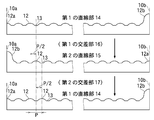
- Development view of the drum body Side view for explaining a straight portion and an intersecting portion of the drum main body Explanatory drawing which shows the arrangement structure of the support part of the drum main-body part FIGS.
- FIGS. 7A to 7C are explanatory views showing the configuration and dimensional relationship of the guide portion and the support portion in the drum main body, and FIGS. 7D and 7E are the configurations of the first and second guide portions.
- FIG. 12A to 12C show an embodiment of a rope feeding mechanism used in the present invention.
- FIG. 12A is a partial cross-sectional view showing the overall configuration
- FIG. 12B is a configuration of a shifter block.
- FIG. 12C is a side view showing the configuration of the main part of the rope feeding mechanism.
- FIG. 17 (a) is a front view showing the overall configuration
- FIG. 17 (b) shows the main configuration of the rope reverse winding detection mechanism.
- FIG. 17 (c) is a side view showing the overall configuration of the rope reverse winding detection mechanism.
- FIGS. 19A to 19C show the no-load detection lever unit of the no-load detection mechanism used in the present invention.
- FIG. 19A is a partial cross-sectional view seen from the no-load detection guide sheave side.
- b) is a side view
- FIG. 19 (c) is a partial sectional view as seen from the guide sheave side.
- FIG. 20 (a) is a front partial sectional view showing the overall configuration
- FIG. 20 (b) shows the main configuration of the no-load detection mechanism.
- FIG. 20C is a side view showing the entire configuration of the no-load detection mechanism.
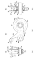
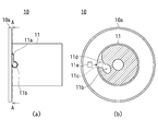
- FIG. 24 (a) is a side view showing the main part of the drum
- FIG. 24 (b) is FIG. AA line cross section (A) to (d): showing a mechanism for preventing the rope end portion from rising in the present embodiment.
- FIG. 25 (a) is an explanatory view showing the configuration of the tip of the conventional rope
- FIG. 25 (b) is an explanatory view showing a case where a conventional rope is fixed to a drum main body
- FIG. 25C is an explanatory view showing a configuration of a tip portion of the rope of the present embodiment
- FIG. 25D is a present embodiment. Explanatory drawing showing the case of fixing the rope to the drum body
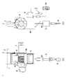
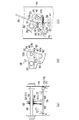
- FIG.1 (a) is a front view which shows the external appearance structure of embodiment of the hoist which is a cargo handling machine based on this invention
- FIG.1 (b) is a side view which shows the external appearance structure of the hoist.
- the hoist 1 of the present embodiment is used in a factory or the like.
- the hoist 1 is hung by a support hook 3 on a support shaft 2 provided at a high place. It is configured.
- the hoist 1 has an apparatus main body 4 in which a drum 10 and the like to be described later are accommodated.
- a rope 20 unwound from the drum 10 is led downward from a main body frame 4a at the lower part of the apparatus main body 4, and the rope 20 The hook 6 provided at the front end portion is moved upward or downward.
- a hollow weight 5 for adjusting the tension of the rope 20 is detachably mounted on the hook 6.
- a DC or AC motor 7 for rotating the drum 10 is provided on one side of the apparatus body 4, and the rotation speed of the drum 10 is controlled on the other side of the apparatus body 4.
- a drive mechanism unit 8 is provided.
- a reduction gear, a clutch mechanism, a brake mechanism, and the like are provided in the drive mechanism unit 8.
- a control unit 9 is provided on the front surface of the main body frame 4a. The control unit 9 controls the driving of the motor 7, and controls the rotation of the motor 7 by an operation switch 9 a connected to the control unit 9.
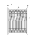
- FIG. 2 is a front view showing an external configuration of the drum in the present embodiment.
- 3 (a) and 3 (b) are front views showing the external configuration of the drum body of the drum, FIG. 3 (a) is a view from one side, and FIG. 3 (b) is a view from the other side. It is a figure.
- FIG. 4 is a development view of the drum main body
- FIG. 5 is a side view for explaining a straight portion and an intersection of the drum main body
- FIG. 6 is an arrangement configuration of support portions of the drum main body. It is explanatory drawing which shows.
- a drum (handling machine drum) 10 of the present embodiment has a cylindrical drum body 11, and first and second flanges are provided at both ends of the drum body 11. 10a and 10b are provided in parallel.
- the rope 20 is wound around the drum main body 11 in multiple layers in parallel.
- the drum body 11 has a plurality of convex curved guide portions 12 provided on the surface thereof at predetermined intervals along the circumferential direction.
- each guide portion 12 is formed in an arc shape in cross section, and a planar support portion 13 is provided between the guide portions 12, for example.
- the surface area of the drum main body 11 includes a first straight portion 14, a second straight portion 15, a first intersecting portion (crossover portion) 16, and a second intersecting portion. It is divided into regions (crossover portions) 17.
- the guide portion 12 and the support portion 13 are formed in a straight line and parallel along the circumferential direction of the drum body portion 11, that is, the direction orthogonal to the rotation axis. Yes.
- the guide portion 12 and the support portion 13 are inclined at a predetermined angle in the same direction with respect to the circumferential direction of the drum body portion 11, that is, the rotation axis, as will be described later. Are formed in parallel in a straight line.
- first and second straight portions 14 and 15 and the first and second intersecting portions 16 and 17 are provided so as to be symmetrical on the surface of the drum main body 11, respectively.
- the first straight portion 14, the first crossing portion 16, the second straight portion 15, and the second straight portion 14 in the winding direction K of the rope 20 with reference to the rope outlet 11 a provided at the crossing portion 17. are provided in the order of the intersections 17 (see FIGS. 4 and 5).
- the 1st and 2nd linear parts 14 and 15 are formed in the same length, and the length of the 1st and 2nd intersection parts 16 and 17 is also formed in the same length.
- first and second straight portions 14 and 15 are set to be longer than the lengths of the first and second intersecting portions 16 and 17, respectively.
- the guide portions 12 and the support portions 13 are respectively in the direction of the rotation axis of the cylinder by 1 ⁇ 2 pitch P between the starting point and the ending point. Inclined so as to be displaced in the (width direction).
- the pitch P of the guide part 12 and the support part 13 means the distance between the top parts of each guide part 12 (refer FIG. 6, FIG. 7 (a)).
- each guide portion 12 and support portion shifts in the rotational axis direction of the cylinder by 1 ⁇ 2 pitch P, and further moves from the second straight portion 15 to the first straight portion 14 via the second intersecting portion 17.
- the part 12 and the support part 13 are displaced by 1/2 pitch P in the rotation axis direction of the cylinder and make a round of the drum main body part 11, each guide part 12 and the support part 13 are in the rotation axis direction of the cylinder.
- the rope 20 is smoothly wound around the first and second straight portions 14 and 15 of the drum main body portion 11, and the end portion thereof will be described later.
- the 1st guide part 12a and the 2nd guide part 12b are provided.
- the first and second guide portions 12 a and 12 b are provided at opposite positions in the first straight portion 14 and the second straight portion 15 of the drum main body portion 11.
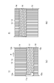
- FIGS. 7A to 7C are explanatory views showing the configuration and dimensional relationship of the guide part and the support part in the drum main body part in the present invention, and FIGS. 7D and 7E show the first and first parts. It is explanatory drawing which shows the structure of 2 guide parts.
- the lower portion of the rope 20 wound around the drum main body 11 is supported at two points by a pair of adjacent guide portions 12 formed in a convex shape (see FIG. 7A).
- the pitch P of the guide portion 12 is set to be slightly larger than the diameter ⁇ of the rope 20 (see FIG. 7A).
- the reason for this is to provide a slight gap between the adjacent first layer ropes 20 wound around the drum main body 11 so that the ropes 20 can be smoothly wound in multiple layers.
- the preferable pitch P of the guide portion 12 is 1.03 to 1.05 times the diameter ⁇ of the rope 20.
- the curvature radius R, width D and height H of the guide portion 12 and the width d of the support portion 13 between the guide portions 12 are the first layer when the rope 20 is wound around the drum body portion 11.
- the distance between the rope 20 and the support portion 13 is set in consideration.
- the preferred curvature radius R of the guide portion 12 is 1 ⁇ 2 of the diameter ⁇ of the rope 20.
- the height H of the guide portion 12 (distance from the support portion 13) is the distance h between the lower portion of the rope 20 and the support portion 13 when the rope 20 is supported by a pair of adjacent guide portions 12. (See FIGS. 7B and 7C).
- first guide portion 12a and the second guide portion 12b are provided at the ends of the first and second linear portions 14 and 15 of the drum main body portion 11 (see FIG. 6). As described below, the first guide portion 12a and the second guide portion 12b are formed so as to have different shapes and sizes (see FIG. 7D).
- the first guide portion 12a is formed continuously with the support portion 13 at one end portion of the drum main body portion 11, and has a shape such that the guide portion 12 is divided into two with respect to the central portion, and the height of the end portion is increased. Is configured to be the highest.
- the end portion of the first guide portion 12a is flush with the inner surface of the first or second flange 10a, 10b (see FIG. 6).
- the first guide portion 12a supports the rope 20 at the end of the first layer together with the adjacent guide portion 12. Therefore, from the viewpoint of reliably guiding and supporting the rope 20, the first guide portion 12a
- the guide portion 12a is preferably formed in the same shape as the inclined surface of the guide portion 12.
- the width and height of the first guide portion 12a are determined so that the first guide portion 12a and the adjacent guide portion 12 support the first layer of rope 20 on the flange side of the rope 20. It is preferable to set so that the portion is supported in contact with the first or second flange 10a, 10b.
- the second guide portion 12b includes a lower guide portion 12b 1 formed continuously with the support portion 13 at the other end of the drum body portion 11, and an upper portion continuous with the lower guide portion 12b 1. and a upper guide portion 12b 2 formed in (see FIG. 7 (e)).
- the lower guide portion 12b 1 of the second guide portion 12b supports the rope 20 at the end of the first layer together with the adjacent guide portion 12, and therefore the viewpoint of reliably guiding and supporting the rope 20 From the above, it is preferable that the shape of the lower guide portion 12b 1 is the same as the inclined surface of the guide portion 12, that is, the same radius of curvature R as that of the guide portion 12.
- the upper guide portion 12b 2 of the second guide portion 12b supports the rope 20 at the end of the second layer together with the rope 20 at the end of the first layer, as will be described later.
- the shape of the upper guide portion 12 b 2 is preferably formed with the same radius of curvature R as the guide portion 12.
- the end portion of the upper guide portion 12b 2 of the second guide portion 12b is flush with the inner surface of the first or second flange 10a, 10b (see FIG. 6).
- the width and height of the second guide portion 12b are such that when the second layer rope 20 is supported by the upper guide portion 12b 2 and the rope 20 at the end of the first layer, the second layer rope 20 is provided. It is preferable to set the side of the flange side so as to contact the first or second flange 10a, 10b.
- the diameter ⁇ of the rope 20 is 5.2 mm.
- the pitch P of the guide portion 12 is 5.4 mm, the curvature radius R of the guide portion 12 is 2.5 to 2.6 mm, and the width D of the guide portion 12 is about 4 mm.
- the height H of 12 is about 1 mm.
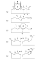
- FIGS. 8A to 8D are diagrams schematically showing a cross-sectional configuration and principle of a drum main body according to the prior art.
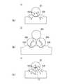
- FIGS. 9A to 9C are diagrams schematically showing the principle of the drum main body of the present invention.
- a guide groove 113 is provided on the surface of the drum main body 111.
- an acute-angle protrusion 112 having a small curvature is formed between the adjacent guide grooves 113.
- the guide groove 113 is formed in a circular arc shape having a radius of curvature r 1 slightly larger than the radius r 0 of the rope 120 having a diameter d 0 , and is provided along the circumference of the drum body 111.
- the radius of curvature r 1 of the guide groove 113 is 0.535 d 0 or more and 0.56 d 0 or less.
- the depth H 0 of the guide groove 113 is 0.28d 0 or more and 0.45d 0 or less.
- the guide grooves 113 are shifted from each other by 1 ⁇ 2 pitch in the first and second linear portions 14, 15 and the first and second intersecting portions 16, 17 in the same manner as in the present invention.
- the guide grooves 113 are provided so as to be continued with a shift of one pitch.
- the rope 120 is wound along the guide groove 113 by the same method as the present invention, and the rope 120 is inclined in the direction opposite to the inclination direction of the lower rope 120 at the first and second intersecting portions 16 and 17. It is designed to be wound up by riding it.
- the load F acts on the cross section of the rope 120 wound around the drum main body 111 from the bottom of the guide groove 113 to the bottom of the guide groove 113 with respect to the cross section.
- the reaction force f acts on the cross section at one point on the drawing (see FIG. 8B).
- the rope 120 is an elastic body, a force does not act at one point, but in order to make the explanation easy to understand, it will be described as a rigid body.
- the radius of curvature r 1 of the guide groove 113 is configured to be larger than the radius r 0 of the rope 120 (see FIG. 8A).
- the guide groove 113 described above is used, and the rope 120 is wound only on the first layer and then used as a multi-layer winding.
- the first layer rope 120 is useless and the environment Causes load.
- the rope 120 may be unwound by mistake, resulting in a dangerous state.
- the convex arcuate guide portion 12 since the convex arcuate guide portion 12 is adopted, for example, when the load is pulled diagonally or wound with no load, a turbulence is generated and the load is lifted as it is. In this case, even when the rope 20 is out of the row and is displaced to the next row or beyond, the cross-sectional shape of the guide portion 12 is close to the radius of the rope 20 and is not a sharp shape as in the prior art. Will not cause damage.
- the first layer rope 20 is supported at two points with respect to the cross section, so that the centering function works on each rope 20.
- the distance between the rows of the ropes 20 of the layer can be stabilized.
- the load acting on the drum main body 11 from the rope 20 can be distributed and received at two points with respect to the cross section, thereby reducing the stress concentration in the rope 20. it can.
- the force acting on the rope 20 from the drum main body 11 can be distributed and received at two points with respect to the cross section, whereby the stress concentration in the rope 20 can be relaxed.
- wear of the drum main body 11 can be reduced and the life of the rope 20 can be extended.
- the rope 20 when an overload is applied to the rope 20 such as at the time of ground cutting (separation from the ground), the rope 20 is a pair of convex guide portions 12A and 12B adjacent to the drum main body portion 11.
- the rope 20 is mainly compressed and deformed, so that the portion of the rope 20 on the drum main body 11 side comes into contact with and is supported by the support portion 13 between the guide portions 12A and 12B of the drum main body 11. (See FIG. 9C).
- the load acting on the drum body 11 from the rope 20 can be distributed and received at three points with respect to the cross section.
- stress concentration in the rope 20 can be reduced.
- the wear of the drum body 11 can be reduced and the life of the rope 20 can be extended.
- the shape of the support portion 13 is not limited to the above-described plane, but may be a convex shape or a concave shape.
- FIG. 10 is a block diagram showing the configuration of the control unit of the present embodiment.
- the control unit 9 of the present embodiment has a rotation control unit 101 for controlling the rotation of the DC motor 7 described above, and the rotation control unit 101 includes the operation described above.
- An up or down instruction signal is input from the switch 9a.
- the rotation control unit 101 sets the acceleration time and deceleration time of the motor 7 and the subsequent constant speed conditions, and outputs an instruction signal based on these settings.
- the rotation control unit 101 is connected to the acceleration / deceleration waveform control unit 102 and the constant velocity waveform control unit 103.
- the acceleration / deceleration waveform control unit 102 receives the acceleration / deceleration signal from the rotation control unit 101, sets the acceleration waveform (soft start) and deceleration waveform (soft stop) of the motor 7, and sets the set drive waveform signal at a predetermined timing. Output to the PWM generator 104.
- the constant speed waveform control unit 103 receives the constant speed signal from the rotation control unit 101, determines the constant speed waveform of the motor 7, and outputs the determined drive waveform signal to the PWM generation unit 104 at a predetermined timing.
- the PWM generation unit 104 generates a PWM waveform at a low voltage based on the drive waveform signals from the acceleration / deceleration waveform control unit 102 and the constant velocity waveform control unit 103, and outputs the PWM waveform signal to the motor drive circuit 105.
- the motor drive circuit 105 converts the PWM waveform signal from the PWM generation unit 104 into a motor output waveform signal, and outputs this signal to the motor 7. With such a configuration, the motor 7 can perform a soft start when starting and a soft stop when stopping.
- the motor 7 is provided with a sensor (not shown) that detects its rotational position and the like, and a position detector 106 that reads the state of the sensor based on a signal from this sensor. It has been. Thereby, the position detection part 106 outputs a stop signal also to the state detection part 107, when the operation
- the state detection unit 107 monitors the state operation of the motor 7, and when receiving a stop signal from the position detection unit 106, outputs a signal to the rotation control unit 101 that all operation instructions should be prohibited. To do. As a result, the rotation control unit 101 stops outputting instruction signals to the acceleration / deceleration waveform control unit 102 and the constant velocity waveform control unit 103. As a result, the rotation operation of the motor 7 is stopped.
- the acceleration signal set in the rotation control unit 101 is changed to a predetermined soft waveform in the acceleration / deceleration waveform control unit 102, and the low voltage is generated in the PWM generation unit 104. After the PWM waveform is generated, the motor 7 is started (soft start).
- Controlling the operation of the motor 7 in this way prevents the occurrence of relative slip between the upper layer portion and the lower layer rope 20 wound around the drum main body portion 11 when the drum 10 is lowered. As a result, the rope 20 can be prevented from being lifted or jumped to the adjacent guide portion 12.
- FIGS. 11A and 11B show the configuration of the drive system of the present embodiment.
- FIG. 11A is an internal front view and FIG. 11B is an internal side view.
- the driving gear 21 is connected to the second flange 10 b on the motor side of the drum 10 provided in the apparatus main body 4. It is attached concentrically with the rotation axis O and is configured to rotate with the drum 10.
- a first transmission gear 23 that rotates about a support shaft 22 provided in the apparatus main body 4 is provided below the drive gear 21, and the first transmission gear 23 meshes with the drive gear 21. It is provided as follows.
- the gear ratio of the first transmission gear 23 is set to be equivalent to that of the driving gear 21. Further, a pinion gear 24 having a smaller number of teeth than the first transmission gear 23 is integrally and concentrically fixed to the first transmission gear 23.
- a rope reciprocating feed screw 30 is provided below the drum 10 in the apparatus body 4.
- the rope reciprocating feed screw 30 is made of an engineering resin (for example, polyacetal, high density polyethylene, nylon resin, carbon fiber, or the like).
- the rope reciprocating feed screw 30 is formed in a straight line and is arranged in parallel with the rotation axis O of the drum 10, and the rotation shaft 31 is rotatably supported by bearings 32 provided on both sides of the main body frame 4 a.
- the rope reciprocating feed screw 30 has a thread groove portion 33 in the middle part thereof, and a shifter block 50 described later meshes with the screw groove portion 33 so that the rope reciprocating feed screw 30 reciprocates at a predetermined speed along the direction in which the rope reciprocating feed screw 30 extends. It is like that.
- a second transmission gear 25 is fixed to the rotary shaft 31 of the rope reciprocating feed screw 30, and the second transmission gear 25 is disposed so as to mesh with the pinion gear 24 described above.
- the number of teeth of the second transmission gear 25 is set to be larger than the number of teeth of the pinion gear 24.
- a rod-shaped guide shaft 40 for guiding a shifter block 50 described later is provided obliquely below the rope reciprocating feed screw 30.
- the guide shaft 40 is formed in a straight line and is arranged in parallel with the rope reciprocating feed screw 30, and both ends thereof are rotatably supported by bearings 43 provided on both sides of the main body frame 4a.
- the driven gear 26 is fixed to the guide shaft 40, and the driven gear 26 is disposed so as to mesh with the second transmission gear 25 described above.
- the number of teeth of the driven gear 26 is set to be smaller than the number of teeth of the second transmission gear 25.
- FIG. 12 (a) to 12 (c) show an embodiment of the rope feeding mechanism used in the present invention.
- FIG. 12 (a) is a partial sectional view showing the entire configuration
- FIG. 12 (b) is a shifter.
- FIG. 12C is a side view showing the configuration of the main part of the rope feed mechanism.
- this rope feed mechanism has a shifter block 50 that is mounted across the rope reciprocating feed screw 30 and the guide shaft 40 described above.
- the shifter block 50 has a main body 51 formed in a rectangular parallelepiped shape, for example.
- the shifter block 50 is configured such that the above-described rope reciprocating feed screw 30 penetrates at one end of the main body 51 and the above-described guide shaft 40 penetrates at the other end of the main body 51. Has been.
- a top 52 having a projection that meshes with the thread groove 33 of the rope reciprocating feed screw 30 is provided, and the top 52 and the thread groove 33 of the rope reciprocating feed screw 30 are engaged with each other.
- the shifter block 50 is configured to reciprocate in the rotational axis direction of the rope reciprocating feed screw 30 as the rope reciprocating feed screw 30 rotates.
- the hoist 1 of the present embodiment performs parallel multi-layer winding by supporting the rope 20 by the convex guide portion 12 provided in the drum main body portion 11 as described above, a conventional parallel grooved drum is used.
- the fleet angle is set to be 90 ° ⁇ 1.5 ° or less with respect to the rotation axis O of the drum 10, and particularly in the vicinity of the first and second flanges 10 a and 10 b. It is necessary to set the fleet angle to be 90 degrees ⁇ about 1.0 to 1.5 degrees so that the transfer of the rope 20 to the road becomes smooth.
- the screw at the central portion of the rope reciprocating feed screw 30 is moved so that the shifter block 50 moves at a slightly smaller pitch than the pitch P of the guide portion 12 described above.
- the angle and speed ratio of the groove 33 are set.
- a guide sheave 53 is provided at the other end of the main body 51 of the shifter block 50.
- the guide sheave 53 moves the rope 20 fed from the drum 10 so as to come to the center position of the hoist 1, and is attached to a position inside the shifter block 50.
- a ball bearing 54 is attached to the guide sheave 53, and a slide bearing 55 is attached inside the ball bearing 54 (see FIG. 12A).
- the slide bearing 55 is attached so as to penetrate in the width direction of the guide sheave 53, and both ends thereof are fixed to the shifter block 50 in a state in which the slide sheave cannot be rotated by, for example, a stop screw (not shown).
- a guide shaft 40 is inserted and arranged concentrically with the guide shaft 40.
- the rope 20 is inserted into a through hole 51 a provided in the middle part of the main body 51 of the shifter block 50, and is engaged with the sheave groove 53 a of the guide sheave 53 to guide the rope 20. (See FIGS. 12A and 12B).
- the rotational power of the drive gear 21 attached concentrically with the rotation axis O of the drum 10 is the first. It is transmitted via the transmission gear 23, the pinion gear 24, and the second transmission gear 25, whereby the rope reciprocating feed screw 30 rotates at a predetermined speed, and the shifter block 50 extends along the direction in which the rope reciprocating feed screw 30 extends.
- the rotational power of the second transmission gear 25 is transmitted to the driven gear 26 fixed to the guide shaft 40, so that the guide shaft 40 rotates.
- the number of teeth of the second transmission gear 25 fixed to the rotary shaft 31 of the rope reciprocating feed screw 30 is the number of teeth of the driven gear 26 fixed to the guide shaft 40.
- the rotational speed of the guide shaft 40 is set to be larger than the rotational speed of the rope reciprocating feed screw 30.
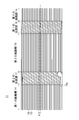
- FIGS. 13 (a) to 13 (d) and FIGS. 14 (a) to 14 (c) are explanatory views showing the operation of winding the rope in the present embodiment around the drum body.
- the cross-sectional configuration of the first straight portion 14 is schematically shown.
- the tip of the rope 20 is fixed to the rope outlet 11a (see FIG. 4) of the drum main body 11, and the drum 10 is rotated and the shifter block 50 is operated to wind the rope 20 in parallel winding.
- the first layer of rope 20A includes a first guide portion 12a on the first flange 10a side, a guide portion 12C adjacent to the first guide portion 12a, 1 (see FIG. 13A).
- the first layer of rope 20A is sequentially applied to the pair of adjacent guide portions 12 toward the second guide portion 12b on the second flange 10b side.
- the second layer rope 20B is connected to the first layer rope 20A at the end on the second guide portion 12b side and the second layer. It rides on the guide portion 12b and is supported by the first layer rope 20A, the upper guide portion 12b2 of the second guide portion 12b, and the second flange 10b (see FIG. 13C).
- the second-layer rope 20B is sequentially supported by the adjacent first-layer rope 20A toward the first flange 10a ( (Refer FIG.13 (d)).
- the second layer rope 20B is inclined in the direction opposite to the inclination direction of the first layer rope 20A, and the first layer It rides on the rope 20A and is wound.
- the third layer rope 20C is supported by the first flange 10a, and the second layer at the end of the first flange 10a side. It rides on the rope 20B of the eye and is supported by the rope 20B of the second layer and the first flange 10a (see FIG. 14A).
- the third layer rope 20C is sequentially supported by the adjacent second layer rope 20B toward the second flange 10b ( (Refer FIG.14 (b)).
- the rope 20C of the third layer is inclined in the direction opposite to the inclination direction of the rope 20B of the second layer, and the second layer It rides on the rope 20B and is wound.
- the fourth layer rope 20D is supported by the second flange 10b, and the third layer on the second flange 10b side end. It rides on the rope 20C of the eye and is supported by the rope 20C of the third layer and the second flange 10b (see FIG. 14C).
- the gear ratio of the driven gear 26 and the second transmission gear 25 is set so that the rotational speed of the guide shaft 40 is 2 to 3 times the rotational speed of the rope reciprocating feed screw 30.
- the slide may not go smoothly due to the presence of dust and the lack of lubrication of the guide shaft 40, which may cause a self-lock and stop moving, but according to this embodiment, Such inconvenience does not occur, and the length of the slide bearing 55 of the guide shaft 40 can be shortened as the friction coefficient is reduced, so that a more compact rope feeding mechanism can be provided. It was.
- the rope reciprocating feed screw used for the conventional hoist and winch was made of a steel material including stainless steel, in this embodiment, by configuring the rope reciprocating feed screw 30 with the above-described engineering resin, Because of its self-lubricating property, oil and grease are not required, and dust can be made difficult to adhere.
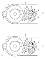
- FIG. 15 is a schematic configuration diagram of an embodiment of a rope reverse winding detection mechanism and a no-load detection mechanism used in the present invention.
- this invention has a rope reverse winding detection mechanism and a no-load detection mechanism so that it may mention later.
- the shifter block 50 below the drum 10 in the main body frame 4a, the shifter block 50, a no-load detection lever unit 80 assembled to the shifter block 50, a limit dog 71, a limit cam 73, and a limit switch 75 are included.
- a load detection mechanism is provided below the drum 10 in the main body frame 4a.
- rope regulating rollers 41 and 42 are provided below the rope reverse winding detection mechanism and the no-load detection mechanism in the main body frame 4a.
- embodiments of the rope reverse winding detection mechanism and the no-load detection mechanism will be described in detail.
- FIG. 16 (a) and 16 (b) show a limit lever unit of the rope reverse winding detection mechanism of the present embodiment.
- FIG. 16 (a) is a side view and FIG. 16 (b) is a front view.
- FIGS. 17 (a) to 17 (c) show the configuration of the rope reverse winding detection mechanism
- FIG. 17 (a) is a front view showing the entire configuration
- FIG. 17 (b) is the rope reverse winding detection.
- FIG.17 (c) is a side view which shows the whole structure of the rope reverse winding detection mechanism.
- the rope reverse winding detection mechanism includes a limit lever unit 60 attached to the shifter block 50 described above.
- the limit lever unit 60 includes a pair of limit levers 61 having the same shape, and a detection roller 62 and a drive roller 63 attached to the pair of limit levers 61. Yes.
- the limit lever 61 is formed, for example, by bending an elongated plate-like member at right angles twice in different directions almost at the middle part, and by making these two limit levers 61 face each other, the drive unit 61a having a small interval between the levers A mounting portion 61b having a larger interval between the levers than the driving portion 61a is provided.
- the interval between the mounting portions 61 b of the pair of limit levers 61 is set to be slightly larger than the width of the shifter block 50.
- the drive part 61a of each limit lever 61 is formed in a straight line shape, and a drive roller 63 is attached to the tip of the limit lever 61 with the drive part 61a sandwiched between the drive parts.
- the drive roller 63 is configured to rotate about a support shaft 64 orthogonal to a straight line in the extending direction of the drive unit 61a.
- each limit lever 61 is formed such that its middle portion is curved in one direction, for example, in a boomerang shape on the same plane, and the radius of curvature of the edge portion 61c inside the curve is the rope reciprocating feed screw. It is set to be slightly larger than the radius of 30.
- the detection roller 62 is attached to the front-end
- the detection roller 62 is configured to rotate around a support shaft 65 parallel to the support shaft 64 of the drive roller 63 described above. Moreover, the detection roller 62 is comprised from the edge part roller 62a provided in the both ends, and the inner side press roller 62b provided inside these edge part rollers 62a.
- the outer diameter of the end roller 62a is set to be slightly larger than the outer diameter of the inner pressing roller 62b.
- the end roller 62a is made of stainless steel, for example.
- the inner pressing roller 62b is made of, for example, stainless steel or resin, and is configured to rotate independently of the end roller 62a.
- the limit lever unit 60 having such a configuration is rotatable around, for example, support shafts 56 provided on both sides of the shifter block 50 in a state where the shifter block 50 is sandwiched between the mounting portions 61b of the pair of limit levers 61. It is attached.
- the support shaft 56 is located in the vicinity of the through hole 51a for the rope reciprocating feed screw 30 of the shifter block 50 (see FIGS. 12A and 12B), and on the inner edge of the curved portion of the mounting portion 61b of each limit lever 61 It is provided in the vicinity of the portion 61c (see FIG. 16A).
- the limit lever unit 60 is configured such that the drive portion 61a is reciprocated by the rope of the shifter block 50 by a tension coil spring 58 having one end attached to a mounting bracket 57a fixed to the end of the shifter block 50 on the rope reciprocating feed screw 30 side. It is comprised so that it may be pulled by the feed screw 30 side edge part (refer FIG.17 (b)).
- a projecting locking portion 59 is provided on the upper portion of the main body 51 of the shifter block 50, that is, on the detection roller 62 side of the limit lever unit 60.
- the locking portion 59 is provided at a position facing the end roller 62a of the detection roller 62 (see FIG. 16B), and the tension coil spring 58 is in a state where no external force acts on the limit lever unit 60.
- the end roller 62a of the detection roller 62 abuts against the locking portion 59 and is locked by the elastic force.
- the limit lever unit 60 is attached such that the detection roller 62 is on the upper side with respect to the rope reciprocating feed screw 30 (shifter block 50).
- a limit dog 71 fixed to the linear rotary support shaft 70 is provided below the rope reciprocating feed screw 30 and on the opposite side of the rope reciprocating feed screw 30 from the guide shaft 40.
- the rotation support shaft 70 is arranged in parallel with the rope reciprocating feed screw 30 and is attached to the main body frame 4a in a rotatable state.
- the limit dog 71 is made of, for example, a plate-like member extending in the direction of the rotation support shaft 70, and the limit lever unit is configured such that one surface (here, the upper surface) is in contact with the drive roller 63 of the limit lever unit 60 described above.
- the dimension (length) of the drive part 61a of 60, the position of the rotation spindle 70, and the size and shape of the limit dog 71 are set (see FIGS. 17A and 17C).
- a torsion coil spring 72 is connected to the limit dog 71, and the end roller 62 a of the detection roller 62 is engaged with the locking portion 59 by the elastic force of the torsion coil spring 72 when no external force is applied to the limit dog 71.
- a torsion coil spring 72 is connected to the limit dog 71, and the end roller 62 a of the detection roller 62 is engaged with the locking portion 59 by the elastic force of the torsion coil spring 72 when no external force is applied to the limit dog 71.
- a limit cam 73 is provided at, for example, one end of the rotation support shaft 70 (see FIG. 17A), and a limit switch is provided at a position facing the arc-shaped cam surface of the limit cam 73, for example. 75 is provided.
- the limit switch 75 is turned off when the limit dog 71 shown in FIG. 17C faces obliquely upward and contacts the driving roller 63 of the limit lever unit 60, and is turned on when the limit dog 71 is pushed down. It is configured.
- 18A and 18B are explanatory views showing the operation of the rope reverse winding detection mechanism.
- the apparatus for performing multi-layer winding as in the present invention, if the row groove of the rope 20 collapses during lowering, a gap is generated between the rows, and the rope 20 is likely to bite into the gap.
- the rope 20 whose path is displaced from the guide shaft 40 side to the rope reciprocating feed screw 30 side pushes the inner pressing roller 62b of the detection roller 62 toward the rope reciprocating feed screw 30, and thereby the limit lever unit 60 is pulled by the tension coil.
- the drive roller 63 provided at the front end of the drive portion 61a of the limit lever unit 60 pushes down the limit dog 71 downward, and the limit switch 75 is turned off. Turn on. Thereby, the lowering operation of the motor 7 is stopped.
- the motor 7 When the operation of the motor 7 is stopped, the motor 7 is operated in the winding direction to return the rope 20 in the reverse winding state to the original position, so that the rope 20 is pressed against the inner pressing roller 62b of the detection roller 62. Since the force no longer acts, the limit lever unit 60 rotates around the support shaft 56 by the elastic force of the tension coil spring 58, returns to the original state shown in FIG. 18A, and the end roller 62a of the detection roller 62 Are brought into contact with the locking portions 59 and locked.
- the inner pressing roller 62b of the detection roller 62 has a smaller roller diameter than the end roller 62a of the detection roller 62, and the end roller 62a is pressed against the locking portion 59 of the shifter block 51. Even if it is a case, it is freely rotatable. For this reason, the inner pressing roller 62b does not rotate with respect to the rope 20, and the sliding rope 20 is not damaged.
- the rope outlet is arranged so that the tip end portion of the rope 20 does not fall out of the drum body 11.
- the female thread portion 11c connected to 11a is fixed by a rope stopper 11e (this point will be described later, see FIGS. 24A and 24B).
- the rope 20 can be wound up again without a problem. Even if the rope 20 is removed from the guide portion 12 of the drum main body portion 11, as described above, the guide portion 12 of the drum main body portion 11 is formed in a convex curved surface shape. There will be no damage.
- FIG. 19 (a) and 19 (b) show the no-load detection lever unit of the no-load detection mechanism used in the present invention.
- FIG. 19 (a) is a partial sectional view as seen from the guide sheave side for no-load detection.
- 19 (b) is a side view
- FIG. 19 (c) is a partial sectional view as seen from the guide sheave side.
- 20 (a) to 20 (c) show the configuration of the no-load detection mechanism
- FIG. 20 (a) is a front partial sectional view showing the entire configuration
- FIG. 20 (b) is the no-load detection mechanism.
- FIG.20 (c) is a side view which shows the whole structure of the no-load detection mechanism.
- the no-load detection mechanism includes the no-load detection lever unit 80 attached to the shifter block 50 described above.
- the no-load detection lever unit 80 includes a pair of no-load detection levers 81 having the same shape, and a no-load detection guide sheave 82 and a driving roller 83 attached to the pair of no-load detection levers 81.
- the no-load detection lever 81 has, for example, an elongated plate-like main body portion 81a, and has a drive projection 81b formed so as to extend obliquely to one side of the main body portion 81a.
- the pair of no-load detection levers 81 is provided inside the shifter block 50.
- the guide sheave 53 used in the rope feed mechanism and the rope reverse winding detection mechanism described above is sandwiched between the pair of no-load detection levers 81 at one end of the main body 81 a of the no-load detection lever 81.
- a no-load detection guide sheave 82 which will be described later, is provided at the other end of the main body 81a of the no-load detection lever 81 (the end on the side where the drive protrusion 81b is provided). 81 so as to be sandwiched by 81.
- a collar 54a is provided on both sides of the ball bearing 54 provided in the guide sheave 53, and the no-load detection lever 81 is configured to rotate around the collar 54a.
- a no-load detection guide sheave 82 is provided between the end portions of the main body 81a of the no-load detection lever 81 on the side where the drive protrusion 81b is provided.
- the no-load detection guide sheave 82 includes a pair of no-load detection levers 81 through which a cylindrical pin 84 provided in parallel with the guide shaft 40 passes, and the pin 84, collar 85, and shaft retaining ring ( It is rotatably mounted via a ball bearing 86 fixed by a not-shown).
- a driving roller 83 is attached to the outer portion of the tip of the driving protrusion 81b of each no-load detection lever 81 so as to be rotatable around a support shaft 87 parallel to the guide shaft 40.
- the no-load detection lever unit 80 having such a configuration is rotatably mounted around the rotation axis of the guide shaft 40 described above at a position inside the shifter block 50 (see FIG. 20B).
- the no-load detection guide sheave 82 and the drive roller 83 of the no-load detection lever unit 80 are positioned below the main body 51 of the shifter block 50, and the drive roller 83 is on the rope reciprocating feed screw 30 side. It is arranged to be located.
- the drive roller 63 of the limit lever 61 described above is arranged and configured so as to enter the inner portion of the tip of the drive protrusion 81b of the no-load detection lever 81 of the no-load detection lever unit 80 (FIGS. 15 and 15). 19 (a)).
- the no-load detection lever unit 80 one end is attached to the mounting bracket 57b fixed to the end of the shifter block 50 on the guide shaft 40 side, and the other end is a pin 84 of the no-load detection lever unit 80 (FIG. 19).
- the driving protrusion 81b is configured to be pulled to the end of the shifter block 50 on the side of the guide shaft 40 by the elastic force of the tension coil spring 58 attached to (a) and (b).
- the rope 20 unwound from the drum body 11 passes through the body 51 from above the body 51 of the shifter block 50 and enters the sheave groove 53 a of the guide sheave 53.
- One side is in contact, passes between the pair of no-load detection levers 81 of the no-load detection lever unit 80, and the other side of the rope 20 contacts the sheave groove 82a of the no-load detection guide sheave 82. Is configured to do.
- the rope 20 hangs directly under the long rollers 41 and 42.
- the rope 20 has the long roller 41 on the side of the guide sheave 53 by the elastic force of the tension coil spring 58 attached to the pin 84 of the no-load detection guide sheave 82 located substantially at the center between the guide sheave 53 and the long roller 41. It is pressed against.
- the spring force is set as follows. In other words, when the tension of the rope 20 during the lowering is larger than a predetermined set value (for example, 8% of the rated load), there is almost no deflection of the rope 20 and no load is detected by the elastic force of the tension coil spring 58.
- the force applied to the rope 20 from the guide sheave 82 and the force applied from the rope 20 to the no-load detection guide sheave 82 based on the tension of the rope 20 are set to be balanced.
- weights of the hook and weight are adjusted so that the tension of the rope 20 is, for example, 8 to 10% so that the limit switch 75 is not turned on when the load is not suspended.
- FIGS. 21A and 21B are explanatory diagrams showing the operation of the no-load detection mechanism.
- the tension of the rope 20 becomes equal to or higher than the set value.
- a compact configuration can be obtained by combining the shifter block 50 and the no-load detection lever unit 80.
- FIGS. 22A and 22B are diagrams showing the configuration of the rope presser mechanism
- FIG. 23 is an explanatory diagram showing the dimensional relationship of the rope presser roller of the rope presser mechanism.
- the rope presser mechanism 90 presses the surface of the rope 20 by the rope presser roller 91 when the rope 20 is wound up and down.
- the rope presser roller 91 is formed in a cylindrical shape, and is attached to the end of one long side of two L-shaped arms 92, for example, so as to be rotatable around the rotation shaft 93.
- An end portion on the short side of each arm 92 is provided so as to be rotatable about a support shaft 94 provided on the upper portion of the apparatus main body 4 of the hoist 1, for example.
- the support shafts 94 provided at both ends of the arm 92 are respectively arranged in parallel with the rotation axis O of the drum 10, so that the rope presser roller 91 is arranged in parallel with the drum main body 11. ing.
- the rope pressing roller 91 is configured to press the rope 20 against the drum body 11 by urging the arm 92 toward the drum body 11 by the elastic force of the torsion coil spring 97 provided on the support shaft 94, for example. Has been.
- a limit cam 95 is attached to the end portion of the arm 92 on the support shaft 94 side, and a limit switch 96 provided in the vicinity thereof is turned on / off in accordance with the operation of the arm 92.
- the rope presser roller 91 is slightly shorter than the width of the drum main body 11, and narrows from the central portion 91a toward the both end portions 91b in the axial direction via the tapered portions 91c.
- the diameter ⁇ D of both end portions 91b of the rope presser roller 91 is configured to be smaller than the diameter ⁇ A of the central portion 91a.
- the reason is as follows. That is, when a rope is wound on a drum having a conventional parallel groove, when the rope is transferred to a layer on one layer and the rope is pressed by means such as a roller, the ropes are stacked in multiple stages. When such a phenomenon occurs, the rope is wound in a random manner. Therefore, when transferring to the upper layer of the rope, it is necessary to make the rope free from contact with other members.
- the pitch is shifted by 0.5 pitch for each layer of the rope.
- the drum main body portion is represented by reference numeral B in FIG. It is necessary not to contact the rope 20 for 1.5 pitches of the 11 guide portions 12.
- the size and the inclination angle of the tapered portion 91c are set.
- the rope 20 being wound is inclined on the first and second intersecting portions 16 and 17 in a direction opposite to the inclination direction of the rope 20 that is one layer below. Wound by.
- the first and second straight portions 14 and 15 and the first and second intersecting portions 16 and 17 are provided so as to be symmetrical on the surface of the drum main body 11 (see FIG. Therefore, the rope 20 wound around the drum main body 11 has an elliptical cross-sectional shape in each layer, and the relative position is also the same.
- FIGS. 25 (a) to 25 (d) show a mechanism for preventing the rope end portion from lifting up in the present embodiment.
- FIG. 24A is a side view showing the main part of the drum
- FIG. 24B is a cross-sectional view taken along line AA of FIG.
- FIG. 25 (a) is an explanatory view showing the configuration of the tip of the conventional rope
- FIG. 25 (b) is an explanatory view showing a case where the conventional rope is fixed to the drum body
- FIG. 25 (c) is an explanatory view showing the configuration of the tip of the rope of the present embodiment
- FIG. 25D is an explanatory view showing a case where the rope of the present embodiment is fixed to the drum body.
- a concave rope housing portion 11b for housing the distal end portion of the rope 20 is provided in the vicinity of the first flange 10a of the drum main body portion 11, and the distal end of the rope 20 is placed in the rope housing portion 11b. It is comprised so that a rope 20 may be pulled out from the rope outlet 11a by inserting a part.
- the rope outlet 11a is formed in, for example, an oval shape extending in the circumferential direction of the drum main body 11, and a cylindrical female screw portion 11c is provided at the rear end portion so as to be connected to the rope outlet 11a. ing.
- the female threaded portion 11c is configured such that a rope stopper 11e, which is a male threaded plug, meshes with the hole to close the hole (see FIG. 24B).
- the rope accommodating portion 11b is provided with a convex curved rope guide portion 11d along the rope outlet 11a.
- the rope guide portion 11d extends from the rope accommodating portion 11b to the tip of the rope outlet 11a. It is formed so that the depth becomes shallower.
- a wire rope used in a cargo handling machine such as the present invention is provided with a bump-shaped lock pipe at its end.
- a rope 120 is inserted into the rope outlet 11a of the drum body 11 and then fixed with the rope stopper 11e, and the rope 120 is wound around the drum body 11, the lock 120a of the rope 120 is A phenomenon occurs in which the adjacent drawn portion 120b slightly floats from the curved surface of the drum main body 11 due to the rigidity of the rope 120 (see FIGS. 25A and 25B).
- the rope 20 of the present embodiment has a distal end portion corresponding to the shape of the portion that guides the rope 20 when the rope 20 is pulled out from the accommodating portion 11b of the drum main body portion 11. Bending is applied.
- bending of an equivalent radius of curvature is performed so that the drawn-out portion 20b on the rear end side in the vicinity of the lock tube 20a at the tip end portion of the rope 20 corresponds to the curved surface shape of the rope guide portion 11d of the drum main body portion 11.
- the routing portion 20c on the rope rear end side of the drawing portion 20b is bent so as to have the same radius of curvature as the surface of the drum body portion 11.
- the lock tube 20a of the rope 20 is locked and fixed by the protruding portion of the rope accommodating portion 11b and the rope stopper 11e.
- the drawn portion 20b of the rope 20 is subjected to, for example, bending processing with an equivalent curvature radius so as to correspond to the curved surface shape of the rope guide portion 11d of the rope 20 of the drum main body portion 11, and further, the drawn portion 20b. Since the bending portion 20c on the rear end portion side of the rope 20 is bent so as to have the same radius of curvature as the surface of the drum body portion 11, the drawing portion 20b of the rope 20 is provided with the drum body portion 11.
- the rope guide portion 11d is in close contact with each other, and the routing portion 20c of the rope 20 is in close contact with the surface of the drum main body portion 11, that is, the pair of guide portions 12.
- the rope 20 attached to the drum 10 does not float at all from the drum main body 11, and as a result, the diameter ⁇ D of the both ends 91b of the rope pressing roller 91 is increased to the limit. It became possible.
- the rope 20 when the rope 20 is wound in multiple layers, it can prevent that the tension
Landscapes
- Engineering & Computer Science (AREA)
- Mechanical Engineering (AREA)
- Transmission Devices (AREA)
Abstract
L'invention concerne un tambour pour équipement de manutention qui permet d'enrouler sur plusieurs niveaux des cordes en enroulement parallèle. Une pluralité de parties guide (12) prenant une forme convexe en surface destinée à maintenir les cordes et à les guider, est agencée à la surface d'une partie corps principal de tambour (11) de forme cylindrique, selon un intervalle prédéfini dans la direction périphérique de la partie corps principal de tambour (11). Les parties guide (12) prennent une forme en arc de cercle en plan transversal avec un rayon de courbure égal ou supérieur au rayon des cordes. Des parties maintien (13) destinées à maintenir les cordes, sont agencées entre les parties guide (12).
Priority Applications (1)
| Application Number | Priority Date | Filing Date | Title |
|---|---|---|---|
| PCT/JP2014/066771 WO2015198413A1 (fr) | 2014-06-25 | 2014-06-25 | Tambour pour équipement de manutention, et équipement de manutention |
Applications Claiming Priority (1)
| Application Number | Priority Date | Filing Date | Title |
|---|---|---|---|
| PCT/JP2014/066771 WO2015198413A1 (fr) | 2014-06-25 | 2014-06-25 | Tambour pour équipement de manutention, et équipement de manutention |
Publications (1)
| Publication Number | Publication Date |
|---|---|
| WO2015198413A1 true WO2015198413A1 (fr) | 2015-12-30 |
Family
ID=54937548
Family Applications (1)
| Application Number | Title | Priority Date | Filing Date |
|---|---|---|---|
| PCT/JP2014/066771 Ceased WO2015198413A1 (fr) | 2014-06-25 | 2014-06-25 | Tambour pour équipement de manutention, et équipement de manutention |
Country Status (1)
| Country | Link |
|---|---|
| WO (1) | WO2015198413A1 (fr) |
Cited By (6)
| Publication number | Priority date | Publication date | Assignee | Title |
|---|---|---|---|---|
| CN110685134A (zh) * | 2019-11-18 | 2020-01-14 | 宁波斯洛曼智能科技有限公司 | 一种晾衣架 |
| CN111302251A (zh) * | 2019-12-27 | 2020-06-19 | 上海宜亮电子科技有限公司 | 一种卷筒 |
| CN112362212A (zh) * | 2020-11-12 | 2021-02-12 | 常州路航轨道装备有限公司 | 受电弓静态拉力检测仪和受电弓静态拉力检测控制方法 |
| CN113788421A (zh) * | 2021-09-10 | 2021-12-14 | 河南东起机械有限公司 | 一种电动葫芦的定点限位折线起升机构 |
| JP7046406B1 (ja) * | 2021-12-07 | 2022-04-04 | 合同会社森林システム研究所 | 集材機及び集材機用ロープ巻き取り装置 |
| CN117878523A (zh) * | 2023-04-27 | 2024-04-12 | 广东宝路盛精密机械有限公司 | 一种电池隔膜生产线 |
Citations (7)
| Publication number | Priority date | Publication date | Assignee | Title |
|---|---|---|---|---|
| JPS53113223U (fr) * | 1977-01-20 | 1978-09-09 | ||
| JPS5563383U (fr) * | 1978-10-26 | 1980-04-30 | ||
| JPS58166590U (ja) * | 1982-04-30 | 1983-11-07 | リョービ株式会社 | 電動ウインチにおける逆巻き防止装置 |
| JPS6145889A (ja) * | 1984-08-03 | 1986-03-05 | 三菱重工業株式会社 | ウインチ装置 |
| JPS63152111U (fr) * | 1987-03-27 | 1988-10-06 | ||
| JPH0233626B2 (ja) * | 1986-07-28 | 1990-07-30 | Fujikura Ltd | Nizukuryodoramuniokerutororisennotanmatsukoteihoho |
| JPH0727019U (ja) * | 1993-10-22 | 1995-05-19 | 松下電工株式会社 | 昇降装置 |
-
2014
- 2014-06-25 WO PCT/JP2014/066771 patent/WO2015198413A1/fr not_active Ceased
Patent Citations (7)
| Publication number | Priority date | Publication date | Assignee | Title |
|---|---|---|---|---|
| JPS53113223U (fr) * | 1977-01-20 | 1978-09-09 | ||
| JPS5563383U (fr) * | 1978-10-26 | 1980-04-30 | ||
| JPS58166590U (ja) * | 1982-04-30 | 1983-11-07 | リョービ株式会社 | 電動ウインチにおける逆巻き防止装置 |
| JPS6145889A (ja) * | 1984-08-03 | 1986-03-05 | 三菱重工業株式会社 | ウインチ装置 |
| JPH0233626B2 (ja) * | 1986-07-28 | 1990-07-30 | Fujikura Ltd | Nizukuryodoramuniokerutororisennotanmatsukoteihoho |
| JPS63152111U (fr) * | 1987-03-27 | 1988-10-06 | ||
| JPH0727019U (ja) * | 1993-10-22 | 1995-05-19 | 松下電工株式会社 | 昇降装置 |
Cited By (8)
| Publication number | Priority date | Publication date | Assignee | Title |
|---|---|---|---|---|
| CN110685134A (zh) * | 2019-11-18 | 2020-01-14 | 宁波斯洛曼智能科技有限公司 | 一种晾衣架 |
| CN111302251A (zh) * | 2019-12-27 | 2020-06-19 | 上海宜亮电子科技有限公司 | 一种卷筒 |
| CN112362212A (zh) * | 2020-11-12 | 2021-02-12 | 常州路航轨道装备有限公司 | 受电弓静态拉力检测仪和受电弓静态拉力检测控制方法 |
| CN112362212B (zh) * | 2020-11-12 | 2022-05-06 | 常州路航轨道装备有限公司 | 受电弓静态拉力检测仪和受电弓静态拉力检测控制方法 |
| CN113788421A (zh) * | 2021-09-10 | 2021-12-14 | 河南东起机械有限公司 | 一种电动葫芦的定点限位折线起升机构 |
| JP7046406B1 (ja) * | 2021-12-07 | 2022-04-04 | 合同会社森林システム研究所 | 集材機及び集材機用ロープ巻き取り装置 |
| WO2023105900A1 (fr) * | 2021-12-07 | 2023-06-15 | 合同会社森林システム研究所 | Treuil et dispositif d'enroulement de câble pour treuil |
| CN117878523A (zh) * | 2023-04-27 | 2024-04-12 | 广东宝路盛精密机械有限公司 | 一种电池隔膜生产线 |
Similar Documents
| Publication | Publication Date | Title |
|---|---|---|
| WO2015198413A1 (fr) | Tambour pour équipement de manutention, et équipement de manutention | |
| CN104976322B (zh) | 容许绳索偏角的槽轮 | |
| EP2694427B1 (fr) | Dispositif de tensionnement | |
| CN102648146A (zh) | 用于绞车总成的改进的匀绕臂 | |
| US8814143B2 (en) | Inclined drum arrangement for winch apparatus | |
| RU2590791C2 (ru) | Приводной агрегат для как минимум одного тягового средства | |
| US9850112B2 (en) | Load bearing apparatus and method | |
| US8702067B2 (en) | Axial displacement device, line deployment system, and a method for deploying a line | |
| ITRA20120027A1 (it) | Attrezzatura industriale | |
| CN204752064U (zh) | 具有排线装置的卷扬机 | |
| US10875739B2 (en) | Detachable line guide | |
| CN106429838A (zh) | 钢丝绳张紧装置、张紧方法及工程机械 | |
| JP2003012279A (ja) | 巻ドラムの乱巻防止装置 | |
| JP5057758B2 (ja) | ワイヤリーリング設備のアンコイラ | |
| US11780713B2 (en) | Rope guiding device and a method for guiding a rope | |
| KR20160096619A (ko) | 이용가능한 견인력이 증가된 승강 시스템 | |
| CN216711392U (zh) | 一种钢索同步排列及绳轮自适应摆动装置 | |
| JP2020158255A (ja) | 線状体監視装置、線状体巻き取り装置、および線状体巻き出し巻き取り方法 | |
| CN110642126B (zh) | 一种采用钢丝绳收放装置的电梯系统 | |
| CN114314329A (zh) | 一种钢索同步排列及绳轮自适应摆动装置 | |
| WO2016096726A1 (fr) | Poulie pour ascenseurs | |
| JP2014037302A (ja) | エレベーター | |
| JP6097726B2 (ja) | 支持装置 | |
| JP2004131192A (ja) | エレベーター装置 | |
| JP2001039682A (ja) | ウインチ装置 |
Legal Events
| Date | Code | Title | Description |
|---|---|---|---|
| 121 | Ep: the epo has been informed by wipo that ep was designated in this application |
Ref document number: 14895492 Country of ref document: EP Kind code of ref document: A1 |
|
| NENP | Non-entry into the national phase |
Ref country code: DE |
|
| NENP | Non-entry into the national phase |
Ref country code: JP |
|
| 122 | Ep: pct application non-entry in european phase |
Ref document number: 14895492 Country of ref document: EP Kind code of ref document: A1 |