WO2015198723A1 - ワイパ装置 - Google Patents
ワイパ装置 Download PDFInfo
- Publication number
- WO2015198723A1 WO2015198723A1 PCT/JP2015/063434 JP2015063434W WO2015198723A1 WO 2015198723 A1 WO2015198723 A1 WO 2015198723A1 JP 2015063434 W JP2015063434 W JP 2015063434W WO 2015198723 A1 WO2015198723 A1 WO 2015198723A1
- Authority
- WO
- WIPO (PCT)
- Prior art keywords
- stop
- wiper
- stop position
- lip
- wiper blade
- Prior art date
- Legal status (The legal status is an assumption and is not a legal conclusion. Google has not performed a legal analysis and makes no representation as to the accuracy of the status listed.)
- Ceased
Links
Images


Classifications
-
- B—PERFORMING OPERATIONS; TRANSPORTING
- B60—VEHICLES IN GENERAL
- B60S—SERVICING, CLEANING, REPAIRING, SUPPORTING, LIFTING, OR MANOEUVRING OF VEHICLES, NOT OTHERWISE PROVIDED FOR
- B60S1/00—Cleaning of vehicles
- B60S1/02—Cleaning windscreens, windows or optical devices
- B60S1/04—Wipers or the like, e.g. scrapers
- B60S1/06—Wipers or the like, e.g. scrapers characterised by the drive
- B60S1/08—Wipers or the like, e.g. scrapers characterised by the drive electrically driven
- B60S1/0896—Wipers or the like, e.g. scrapers characterised by the drive electrically driven including control systems responsive to a vehicle driving condition, e.g. speed
-
- B—PERFORMING OPERATIONS; TRANSPORTING
- B60—VEHICLES IN GENERAL
- B60S—SERVICING, CLEANING, REPAIRING, SUPPORTING, LIFTING, OR MANOEUVRING OF VEHICLES, NOT OTHERWISE PROVIDED FOR
- B60S1/00—Cleaning of vehicles
- B60S1/02—Cleaning windscreens, windows or optical devices
- B60S1/04—Wipers or the like, e.g. scrapers
- B60S1/06—Wipers or the like, e.g. scrapers characterised by the drive
- B60S1/08—Wipers or the like, e.g. scrapers characterised by the drive electrically driven
- B60S1/0814—Wipers or the like, e.g. scrapers characterised by the drive electrically driven using several drive motors; motor synchronisation circuits
-
- B—PERFORMING OPERATIONS; TRANSPORTING
- B60—VEHICLES IN GENERAL
- B60S—SERVICING, CLEANING, REPAIRING, SUPPORTING, LIFTING, OR MANOEUVRING OF VEHICLES, NOT OTHERWISE PROVIDED FOR
- B60S1/00—Cleaning of vehicles
- B60S1/02—Cleaning windscreens, windows or optical devices
- B60S1/04—Wipers or the like, e.g. scrapers
- B60S1/28—Wipers or the like, e.g. scrapers characterised by a plurality of wipers
-
- B—PERFORMING OPERATIONS; TRANSPORTING
- B60—VEHICLES IN GENERAL
- B60S—SERVICING, CLEANING, REPAIRING, SUPPORTING, LIFTING, OR MANOEUVRING OF VEHICLES, NOT OTHERWISE PROVIDED FOR
- B60S1/00—Cleaning of vehicles
- B60S1/02—Cleaning windscreens, windows or optical devices
- B60S1/04—Wipers or the like, e.g. scrapers
- B60S1/06—Wipers or the like, e.g. scrapers characterised by the drive
Definitions
- the present invention relates to a wiper device in which the tip side of the lip is directed in a different direction each time the wiper blade stops.
- a wiper device that secures the visibility of the driver and passengers.
- a motor device whose output shaft is rotationally driven in forward and reverse directions is used.
- the wiper member is swung within a predetermined wiping range, and as a result, rainwater or the like adhering to the wiping surface is wiped off.
- the wiper member includes a wiper arm that is swingably provided on the vehicle body, and a wiper blade that is attached to the distal end side of the wiper arm.
- the wiper blade has a blade rubber, and the lip of the blade rubber is pressed toward the wiping surface by the spring force of a tension spring provided at the base end portion of the wiper arm. As a result, the blade rubber is prevented from being lifted by a traveling wind or the like, and as a result, good wiping performance is ensured.
- Patent Document 1 discloses a technique in which the direction in which the tip side of the lip faces is periodically changed to thereby suppress the plastic deformation of the blade rubber.
- Patent Document 1 includes a control unit (controller) that controls the rotation of the output shaft of the wiper motor in the forward and reverse directions, and the control unit is provided each time when the ignition switch is turned on or off.
- the wiper blade is moved between the first stop position and the second stop position. Thereby, the direction in which the tip side of the lip faces is changed, and the blade rubber is prevented from being plastically deformed.
- the movement distance of the wiper blade for changing the direction in which the tip side of the lip faces is shortened. Therefore, when the blade rubber is hardened due to use in a cold region or the like, the direction in which the tip side of the lip faces cannot be changed. In this case, the plastic deformation of the blade rubber becomes stronger, which may cause a problem that the wiping performance of the blade rubber is significantly lowered.
- An object of the present invention is to provide a wiper device that can reliably change the direction in which the tip side of the lip faces at a predetermined stop position without frequently changing the direction in which the tip side of the lip faces.
- each time the wiper blade stops a wiper device in which the tip end side of the lip is directed in a different direction, the tip end side of the lip being above the wiping surface on the wiping surface with which the lip slides.
- a first stop position that is stopped in a state facing toward the side
- a second stop position that is stopped in a state in which the tip side of the lip is directed toward the lower side of the wiping surface
- a stop operation of the wiper blade A lower limit position during a stop operation that is a lower limit position and an upper limit position during a stop operation that is an upper limit position during the stop operation of the wiper blade are defined, and when the number of vehicle speed detections reaches a predetermined number, the lip
- the wiper blade is once moved to the lower limit position during the stop operation and then moved to the second stop position to stop the wiper blade. Tsu when the distal end side of the flop is in the second stop position, the wiper blade, the stop moves to the first stop position after moving once the stop operation at the
- the first stop position is provided below the wiping surface, and the second stop position is provided above the wiping surface relative to the first stop position.
- the lower limit position during the stop operation is provided below the wiping surface from the first stop position, and the upper limit position during the stop operation is above the wiping surface from the second stop position.
- the wiper device is directed so that the tip end side of the lip is directed in a different direction, and the tip end side of the lip is on the wiping surface on the wiping surface with which the lip slides.
- a third stop position is defined in which the tip end side of the lip is stopped in a state in which the tip end side is directed upward of the wiping surface, and when the vehicle speed detection count reaches a predetermined number, the tip end side of the lip is First stop position Alternatively, when the wiper blade is in the third stop position, the wiper blade is once moved to the lower limit position during the stop operation, and then moved to the second stop position to stop the lip. If it is in the second stop position, the wiper blade is moved to the third stop position and stopped.
- the first stop position is provided below the wiping surface, and the second stop position is provided above the wiping surface relative to the first stop position. It is done.
- the wiper blade when the number of times of detection of the vehicle speed reaches the predetermined number of times, if the tip end side of the lip is at the first stop position, the wiper blade is once moved to the lower limit position during the stop operation. If the tip end side of the lip is at the second stop position, the wiper blade is temporarily moved to the upper limit position during the stop operation and then moved to the first stop position. Stop.
- the wiper blade can be stopped at each of the first stop position and the second stop position while increasing the amount of movement of the wiper blade, and as a result, the direction in which the tip side of the lip faces in each stop position is ensured. Can be changed to
- FIG. 5 is an explanatory diagram for explaining a lip folding operation according to the first embodiment.
- 6 is a flowchart for explaining a lip folding operation (every wiper blade stop) in FIG. 4.
- 5 is a flowchart for explaining a lip folding operation (number of times of vehicle speed detection) in FIG. 4.
- 10 is an explanatory diagram for explaining a lip folding operation according to Embodiment 2.
- FIG. It is a flowchart explaining the lip folding operation
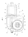
- FIG. 6 is a diagram illustrating details of a wiper motor according to a third embodiment.
- FIG. 10 illustrates a wiper device according to a fourth embodiment.
- FIG. 2 is a diagram showing an example of application of the wiper device of FIG. 1 to a vehicle
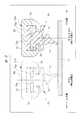
- FIG. 2 is a diagram showing details of the wiper motor
- FIG. 3 is a diagram explaining stop states A and B of the wiper blade
- FIG. FIG. 5 is a flowchart for explaining the lip folding operation (every wiper blade stop) in FIG. 4
- FIG. 6 is a flowchart for explaining the lip folding operation (number of vehicle speed detections) in FIG. Each of the flowcharts to be described is shown.
- a windshield 11 is provided on the front side of a vehicle 10 such as an automobile.
- a wiper device 12 is provided that wipes rainwater and the like attached to the wiping surface of the windshield 11 to ensure the visibility of the driver and passengers.
- the wiper device 12 includes a DR wiper motor 20 disposed on the DR side (driver's seat side) of the vehicle 10 and an AS side wiper motor 30 disposed on the AS side (passenger seat side) of the vehicle 10. These wiper motors 20 and 30 are formed in the same manner, and are disposed opposite to the left and right sides of the vehicle 10.
- the wiper motors 20 and 30 have a DR-side wiper member 21 and an AS-side wiper member 31.
- the DR-side wiper member 21 includes a DR-side wiper arm 21a and a DR-side wiper blade 21b
- the AS-side wiper member 31 includes an AS-side wiper arm 31a and an AS-side wiper blade 31b.
- the base ends of the wiper arms 21a and 31a are fixed to the output shafts 22 and 32 of the wiper motors 20 and 30, and the wiper motors 20 and 30 directly swing the wiper members 21 and 31 without using a link mechanism or the like. ing. That is, the wiper device 12 is a counter-wiping type direct drive wiper device.
- the wiper blades 21b and 31b are reciprocally wiped within a wiping range of approximately 90 ° between the lower inversion position LRP and the upper inversion position URP.
- the wiper motors 20 and 30 detect the rotational positions of the output shafts 22 and 32 to cause the wiper blades 21b and 31b to perform a reverse operation at the lower reverse position LRP and the upper reverse position URP.
- the storage position SL is provided below the windshield 11 with respect to the lower inversion position LRP.
- the storage position SL indicates a stop position at which the wiper blades 21b and 31b are moved when the wiper device 12 is stopped by turning off the wiper switch 14.
- the DR-side control board 23 and the AS-side control board 33 are accommodated in the wiper motors 20 and 30.
- a communication line 13 is provided between the control boards 23 and 33, and the wiper motors 20 and 30 communicate with each other via the communication line 13.
- the rotational position information of the output shafts 22 and 32 (position information of the wiper blades 21b and 31b) is communicated with each other via the communication line 13, so that the wiper blades 21b and 31b are wiped back and forth without colliding on the windshield 11. It is operating.
- the wiper switch 14 provided in the passenger compartment (not shown) is connected to the AS-side control board 33.
- the wiper motors 20 and 30 are rotationally controlled at high speed (High), low speed (Low), or intermittently (Int).
- an ignition switch 15 provided in the passenger compartment is connected to the AS-side control board 33, and the wiper device 14 can be operated by the wiper switch 14 when the operator operates the ignition switch 15.
- a vehicle speed sensor 16 for detecting the vehicle speed (Vkm / h) of the vehicle 10 is connected to the AS-side control board 33, and information from the vehicle speed sensor 16 is used as a trigger for a lip folding operation described later. It is done.
- other information such as rotational speed information of the wiper motors 20 and 30 is also transmitted to and from the communication line 13.
- the DR side wiper motor 20 and the AS side wiper motor 30 are formed in the same manner. Therefore, hereinafter, the detailed description of the AS-side wiper motor 30 will be omitted, and the detailed structure of the DR-side wiper motor 20 will be described.
- the DR-side wiper motor 20 includes a motor unit 40 and a gear unit 50 connected thereto.
- the motor unit 40 includes a yoke 41 formed into a bottomed cylindrical shape by pressing a steel plate made of a magnetic material, and a plurality of permanent magnets 42 are provided inside the yoke 41. Inside these permanent magnets 42, an armature 43 is rotatably provided through a predetermined gap (air gap), and a coil (not shown) is wound around the armature 43 with a predetermined winding method and the number of turns. It is disguised.
- the armature shaft 44 penetrates and is fixed to the rotation center of the armature 43, and the base end side (right side in the figure) of the armature shaft 44 rotates to the bottom portion of the yoke 41 via a radial bearing (not shown). It is supported freely. Further, the distal end side (left side in the drawing) of the armature shaft 44 extends into the case 51 of the gear portion 50.
- a worm 45 is integrally provided on the distal end side of the armature shaft 44, and the worm 45 is engaged with a tooth portion 52 a of the worm wheel 52.
- the worm 45 and the worm wheel 52 form a speed reduction mechanism SD, and the speed reduction mechanism SD reduces the rotation of the armature shaft 44 to increase the torque.
- the high torque rotation is output to the DR-side wiper arm 21a (see FIG. 1) via the output shaft 22 fixed to the worm wheel 52.
- a commutator 46 is provided at a position near the armature 43 of the armature shaft 44.
- the end of the coil is electrically connected to the commutator 46, and a pair of brushes 47 are in sliding contact.
- a drive current flows to the coil via the commutator 46, an electromagnetic force is generated in the armature 43, and consequently the armature shaft 44 is forward or backward.
- a predetermined rotational speed At a predetermined rotational speed.
- the worm wheel 52 is rotatably accommodated in the case 51 of the gear unit 50, and the rotation from the worm 45 is transmitted to the worm wheel 52.
- a proximal end side of the output shaft 22 is fixed to the worm wheel 52, and a distal end side of the output shaft 22 extends to the outside of the case 51.
- the output shaft 22 is connected to the proximal end side of the DR-side wiper arm 21a (see FIG. 1).
- a sensor magnet 53 formed in a substantially disk shape is attached to the front side surface 52b of the worm wheel 52.
- the sensor magnet 53 is rotated together with the worm wheel 52.
- One side along the radial direction of the sensor magnet 53 is magnetized to the N pole, and the other side along the radial direction of the sensor magnet 53 is magnetized to the S pole. That is, the sensor magnet 53 is magnetized to the N pole and the S pole (two poles) at intervals of 180 ° along the circumferential direction.
- the opening part (front side in the figure) of the case 51 is closed by a cover member (not shown).
- a DR-side control board 23 (two-dot chain line in the figure) is mounted on the inner side of the cover member so as to face the front side surface 52b of the worm wheel 52, whereby the DR-side control board 23 is accommodated inside the gear portion 50.
- the DR-side control board 23 controls the motor unit 40.
- the DR-side control board 23 includes a plurality of electronic components (not shown) such as transistors and resistors, and a CPU having a RAM, a ROM, and the like.
- a controller 23a is mounted.
- an MR sensor (magnetoresistance element) 23b is mounted on a portion of the DR-side control board 23 that faces the sensor magnet 53.
- the MR sensor 23b outputs electrical signals (amount of change in resistance value) having different magnitudes depending on the direction of the magnetic flux across the MR sensor 23b. Then, an electrical signal from the MR sensor 23b generated by the relative rotation of the sensor magnet 53 is sent to the controller 23a.
- the controller 23a grasps the rotation position and rotation speed of the worm wheel 52 with respect to the case 51, that is, the position and movement speed of the DR-side wiper blade 21b with respect to the windshield 11 according to the magnitude of the electrical signal from the MR sensor 23b. To do. Thereby, the DR-side wiper member 21 can be reversed or stopped at the storage position SL (see FIG. 1).
- the DR side wiper blade 21b and the AS side wiper blade 31b are both formed in the same manner. Therefore, hereinafter, the description of the AS-side wiper blade 31b will be omitted, and the detailed structure thereof will be described on behalf of the DR-side wiper blade 21b.
- the DR-side wiper blade 21 b includes a blade holder 60 and a blade rubber 70 held by the blade holder 60.
- the blade rubber 70 has a lip 71, a main body portion 72, and a neck portion 73.
- the cross-sectional shape of the blade rubber 70 is the same in the entire region along the longitudinal direction of the blade rubber 70.
- the cross-sectional shape of the lip 71 is formed in a substantially triangular shape, and the tapered tip end portion of the lip 71 is in contact with the wiping surface of the windshield 11.
- the cross-sectional shape of the main body 72 is formed in a substantially rectangular shape, and the main body 72 is provided with a pair of spring accommodating grooves 72 a along the longitudinal direction of the blade rubber 70.
- a pair of vertebras (spring members) 74 made of a long flat steel material are mounted in the spring accommodating grooves 72a. These vertebras 74 are curved so as to have a radius of curvature smaller than the radius of curvature of the windshield 11 under a natural state in which no external force is applied.
- the blade rubber 70 is elastically deformed in accordance with the curvature radius of the windshield 11 by the spring force of the vertibra 74, and as a result, the entire longitudinal direction of the lip 71 is pressed (adhered) to the wiping surface of the windshield 11.
- the neck portion 73 connects the lip 71 and the main body 72.
- the thickness dimension along the wiping direction (the left-right direction in the figure) of the neck portion 73 is the thinnest compared to other portions of the blade rubber 70 and can be easily elastically deformed.
- a tension spring (not shown) provided at the base end portion of the DR-side wiper arm 21a (see FIG. 1).
- the neck portion 73 is tilted in the wiping direction.
- the lip 71 is brought into sliding contact with the wiping surface in a tilted state.
- the rain water etc. which adhered to the wiping surface at the corner
- the direction to which the front end side of the lip 71 faces changes according to the wiping direction, generation of chatter noise during the wiping operation is effectively suppressed.
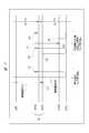
- FIG. 4 schematically shows the wiping surface of the windshield 11, and the solid line arrow in the figure indicates the path along which the DR-side wiper blade 21b can move.
- circles (1) to (6) indicate the stop position (storage position) of the DR-side wiper blade 21b (the tip side of the lip 71).
- area 1 and area 2 indicated by broken-line arrows in the figure indicate a lower area and an upper area of windshield 11 centered on storage position SL, and area 1 is located on the lower side and cannot be seen from the driver's seat.
- the area 2 indicates an area that can be viewed from the driver's seat relatively easily by looking into the upper side.
- the stop position of the DR-side wiper blade 21b is two places: a lower stop position (first stop position) APS1 or an upper stop position (second stop position) APS2.
- the lower side stop position APS1 is provided on the lower side (lower side in the figure) of the wiping surface
- the upper side stop position APS2 is provided on the upper side (upper side in the figure) of the wiping surface than the lower side stop position APS1. Yes.
- the DR wiper blade 21b is stopped at the lower stop position APS1, as shown in “stop state A” in FIG. 3, the tip end side of the lip 71 faces the upper side of the wiping surface.
- the DR wiper blade 21b is stopped at the upper stop position APS2, as shown in “stop state B” in FIG. 3, the tip end side of the lip 71 faces the lower side of the wiping surface.
- a lower limit position EPSL during stop operation that is a lower limit position during stop operation of the DR wiper blade 21b is provided below the wiping surface from the lower stop position APS1.
- the upper limit position during the stop operation that is the upper limit position during the stop operation of the DR-side wiper blade 21b is located above the wiping surface above the upper stop position APS2 and below the lower inverting position LRP.
- An EPSU is provided.
- the DR-side wiper blade 21b is reciprocated between the lower inversion position LRP and the upper inversion position URP. Accordingly, in the region below the windshield 11 from the lower inversion position LRP in FIG. 4, when the ignition switch 15 is turned on and the wiper switch 14 is turned off, the DR-side wiper blade 21b arrives. It is an area to gain.
- the movement control of the DR-side wiper blade 21b to the four positions (APS1, APS2, EPSL, EPSU) defined on the wiping surface of the windshield 11 is controlled by the MR sensor 23b (see FIG. This is performed by grasping the position of the DR-side wiper blade 21b with respect to the windshield 11 based on the electrical signal from 2).
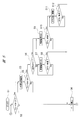
- FIGS. 5 and 6 are started by turning on the ignition switch 15 (step S1).
- the execution and determination in all steps shown in FIGS. 5 and 6 are processed in the controller 23a (see FIG. 2).
- step S2 it is determined whether or not the wiper switch 14 is on. If it is determined in step S2 that the wiper switch 14 is on (Yes), the process proceeds to step S3, where a driving current is supplied to the DR-side wiper motor 20 to perform a reciprocating wiping operation. On the other hand, if it is determined (No) in step S2 that the wiper switch 14 is off (OFF), the process proceeds to step S4, and the stop state of the DR-side wiper motor 20 is maintained.
- step S5 it is determined whether or not the wiper switch 14 is turned off. If it is determined in step S5 that the wiper switch 14 is off (Yes), the process proceeds to step S6. On the other hand, if it is determined (No) in step S5 that the wiper switch 14 is on (ON), the process returns to step S3, and the DR-side wiper motor 20 is continuously operated for reciprocal wiping.
- the controller 23a performs the DR-side wiper between the lower inversion position LRP and the upper inversion position URP based on the electrical signal from the MR sensor 23b (see FIG. 2). The blade 21b is reciprocated.
- step S6 based on the determination result that the wiper switch 14 is turned off, it is determined whether or not the previous stop position of the DR wiper blade 21b is the lower stop position APS1.
- the past stop position information of the DR wiper blade 21b is obtained from information stored in the RAM or the like of the controller 23a. If it is determined in step S6 that the previous stop position of the DR-side wiper blade 21b was the upper-side stop position APS2 (No), the process proceeds to step S7, and the storage operation (A) shown in FIG. 4 is executed. .
- step S7 and step S8 means that the DR-side wiper blade 21b is moved to the lower side of the windshield 11 beyond the lower inversion position LRP, and is directed to the lower-side stop position APS1. It is an action to dodge.
- step S8 it is determined whether or not the DR side wiper blade 21b has reached the lower side stop position APS1. If it is determined in step S8 that the lower stop position APS1 has been reached (Yes), the process proceeds to step S4, the supply of drive current to the DR wiper motor 20 is stopped, and the DR wiper motor 20 is stopped. As a result, the DR-side wiper blade 21b stops at the position of the black circle (1) in FIG. 4, and enters the “stop state A” shown in FIG. The direction of facing can be changed to face in a different direction. On the other hand, if it is determined in step S8 that the lower stop position APS1 has not yet been reached (No), the process returns to step S7 to continue the storage operation (A).
- step S6 If it is determined in step S6 that the previous stop position of the DR-side wiper blade 21b is the lower stop position APS1 (Yes), the process proceeds to step S9 to execute the storing operation (B) shown in FIG. .
- the storing operation (B) performed in step S9 to step S12 means that the DR-side wiper blade 21b is moved to the lower side of the windshield 11 beyond the lower inversion position LRP to reach the lower limit position EPSL during the stop operation. This is an operation in which the DR-side wiper motor 20 is reversely rotated and moved toward the upper stop position APS2 after being moved once.
- step S10 it is determined whether or not the DR-side wiper blade 21b has reached the lower limit position EPSL during the stop operation. If it is determined in step S10 that the stop operation lower limit position EPSL has been reached (Yes), the process proceeds to step S11, and the DR-side wiper motor 20 is rotated in the reverse direction. Thereby, the DR side wiper blade 21b is driven to the upper side stop position APS2 side and moved to the upper side of the windshield 11 (see FIG. 4). On the other hand, if it is determined in step S10 that the stop operation lower limit position EPSL has not yet been reached (No), the process returns to step S9 to continue the storage operation (B).
- step S12 it is determined whether or not the DR-side wiper blade 21b has reached the upper stop position APS2. If it is determined in step S12 that the upper stop position APS2 has been reached (Yes), the process proceeds to step S4, the supply of drive current to the DR wiper motor 20 is stopped, and the DR wiper motor 20 is stopped. As a result, the DR-side wiper blade 21b stops at the position of the black circle (2) in FIG. 4, and enters the “stop state B” shown in FIG. The direction of facing can be changed to face in a different direction. On the other hand, if it is determined in step S12 that the upper stop position APS2 has not yet been reached (No), the process returns to step S11 to continue the storage operation (B).
- steps S13 to S24 regardless of the on / off operation of the wiper switch 14, the direction in which the tip side of the lip 71 faces is different between “stop state A” and “stop state B” in FIG. A process of reliably changing, that is, a lip folding operation is executed.
- step S13 it is determined whether or not the number of times the vehicle speed signal is input from the vehicle speed sensor 16, that is, the number of times the vehicle speed is detected is a predetermined n times or more. If it is determined in step S13 that the number of vehicle speed detections is less than the predetermined n times (No), a return process is returned to step S2 in FIG. On the other hand, if it is determined in step S13 that the number of vehicle speed detections is greater than or equal to the predetermined n (Yes), the process proceeds to step S14, and the lip folding operation is executed in the subsequent steps. That is, the controller 23a performs a lip folding operation every time the number of vehicle speed detections is n times or more.
- the number n of vehicle speed detections is set to 5 times, for example. Accordingly, it is not necessary to frequently change the direction in which the tip side of the lip 71 faces each time the ignition switch is turned on or off as before, and thus the early deterioration of the lip 71 is prevented.
- step S14 it is determined whether or not the DR wiper blade 21b is currently stopped at the lower stop position APS1. If it is determined in step S14 that the position is the lower stop position APS1 (Yes), the process proceeds to step S15, the drive current is supplied to the DR wiper motor 20, and the DR wiper blade 21b is moved to the lower limit position EPSL side during the stop operation. To drive.
- step S16 it is determined whether or not the DR-side wiper blade 21b has reached the lower limit position EPSL during the stop operation. If it is determined in step S16 that the stop operation lower limit position EPSL has been reached (Yes), the process proceeds to step S17, and the DR-side wiper motor 20 is rotated in the reverse direction. Thereby, the DR side wiper blade 21b is driven to the upper side stop position APS2 side and moved to the upper side of the windshield 11 (see FIG. 4). On the other hand, if it is determined in step S16 that the stop operation lower limit position EPSL has not yet been reached (No), the process returns to step S15 to continue the movement to the stop operation lower limit position EPSL.
- step S18 it is determined whether or not the DR wiper blade 21b has reached the upper stop position APS2. If it is determined in step S18 that the upper stop position APS2 has been reached (Yes), the process proceeds to step S19, the supply of drive current to the DR-side wiper motor 20 is stopped, and the DR-side wiper motor 20 is stopped. As a result, the DR-side wiper blade 21b is moved from the position of the white circle (3) in FIG. 4 to the position of the black circle (4) to change from “stop state A” to “stop state B” shown in FIG. The direction in which the front end side of 71 is directed is changed so as to be directed in a different direction.
- step S18 determines whether the upper stop position APS2 has not yet been reached (No)
- the process returns to step S17 to continue the movement to the upper stop position APS2.
- step S19 the return process returned to step S2 in FIG. 5 is executed.
- step S14 If it is determined in step S14 that the upper stop position APS2 is reached (No), the process proceeds to step S20, where a drive current is supplied to the DR wiper motor 20, and the DR wiper blade 21b is moved to the upper limit position EPSU during stop operation. To drive.
- step S21 it is determined whether or not the DR-side wiper blade 21b has reached the upper limit position EPSU during the stop operation. If it is determined in step S21 that the stop operation upper limit position EPSU has been reached (Yes), the process proceeds to step S22, and the DR-side wiper motor 20 is rotated in the reverse direction. Accordingly, the DR-side wiper blade 21b is driven to the lower side stop position APS1 side and moved to the lower side of the windshield 11 (see FIG. 4). On the other hand, if it is determined in step S21 that the stop operation upper limit position EPSU has not yet been reached (No), the process returns to step S20 to continue the movement to the stop operation upper limit position EPSU.
- step S23 it is determined whether or not the DR-side wiper blade 21b has reached the lower stop position APS1. If it is determined in step S23 that the lower stop position APS1 has been reached (Yes), the process proceeds to step S24, the supply of drive current to the DR wiper motor 20 is stopped, and the DR wiper motor 20 is stopped. As a result, the DR-side wiper blade 21b is moved from the position of the white circle (5) in FIG. 4 to the position of the black circle (6) to change from the “stop state B” to the “stop state A” shown in FIG. The direction in which the front end side of 71 is directed is changed so as to be directed in a different direction.
- step S23 determines whether the lower stop position APS1 has not yet been reached (No)
- the process returns to step S22 to continue the movement to the lower stop position APS1.
- step S24 the return process returned to step S2 in FIG. 5 is executed.
- the vehicle travels directly between the lower side stop position APS1 and the upper side stop position APS2. Without moving, it is temporarily moved to the lower limit position EPSL during stop operation or the upper limit position EPSU during stop operation. Thereby, the movement amount of the DR-side wiper blade 21b (blade rubber 70) is increased, and the direction in which the front end side of the lip 71 is directed is surely changed to be directed in a different direction.
- the folding operation of the lip 71 is performed in the area 1 and in the area below the windshield 11 with respect to the lower inversion position LRP of the area 2, so that it is conspicuous to the driver and passengers. There is nothing. Therefore, there is no concern that the wiper device 12 is malfunctioning.
- the wiper device 12 when the front end side of the lip 71 is at the lower stop position APS1 when the number of vehicle speed detections reaches the predetermined number n.
- the DR wiper blade 21b is temporarily moved to the lower limit position EPSL during the stop operation and then moved to the upper stop position APS2 and stopped, and the tip side of the lip 71 is at the upper stop position APS2, the DR side The wiper blade 21b is once moved to the upper limit position EPSU during the stop operation and then moved to the lower stop position APS1 and stopped.
- the DR wiper blade 21b can be stopped at each of the lower stop position APS1 and the upper stop position APS2 while increasing the amount of movement of the DR wiper blade 21b.
- the respective stop positions APS1, APS2
- the direction in which the tip side of the lip 71 faces can be reliably changed.
- FIG. 7 is an explanatory diagram for explaining the lip folding operation of the second embodiment
- FIG. 8 is a flowchart for explaining the lip folding operation of FIG. 7 (every stop of the wiper blade)
- FIG. 9 is a lip folding operation of FIG. The flowchart explaining the frequency
- the position where the DR-side wiper blade 21b defined on the wiping surface of the windshield 11 can move is different from that in the first embodiment. Specifically, the difference is that the second lower stop position (third stop position) APS3 is defined instead of the upper limit position EPSU (see FIG. 4) during stop operation in the first embodiment.
- the second lower stop position APS3 is defined instead of the upper limit position EPSU (see FIG. 4) during stop operation in the first embodiment.
- APS1 is set as the first lower stop position.
- the second lower stop position APS3 is provided between the first lower stop position APS1 and the stop operation lower limit position EPSL and closer to the stop operation lower limit position EPSL. Accordingly, the amount of movement between the first lower stop position APS1 and the second lower stop position APS3 is set to be relatively large.
- the tip end side of the lip 71 faces the upper side of the wiping surface. State.
- step S32 it is determined whether or not the wiper switch 14 is on. If it is determined in step S32 that the wiper switch 14 is on (Yes), the process proceeds to step S33, where a driving current is supplied to the DR-side wiper motor 20 to perform a reciprocating wiping operation. On the other hand, if it is determined (No) in step S32 that the wiper switch 14 is off (OFF), the process proceeds to step S34 and the stopped state of the DR-side wiper motor 20 is maintained.
- step S35 it is determined whether or not the wiper switch 14 is turned off. If it is determined in step S35 that the wiper switch 14 is off (Yes), the process proceeds to step S36. On the other hand, if it is determined (No) in step S35 that the wiper switch 14 is on (ON), the process returns to step S33, and the DR-side wiper motor 20 is continuously operated for reciprocating wiping.
- step S36 based on the determination result that the wiper switch 14 has been turned off, the previous stop position of the DR wiper blade 21b (the tip side of the lip 71) is the first lower stop position APS1 or the second lower side. It is determined whether or not the stop position APS3. If it is determined in step S36 that the previous stop position of the DR-side wiper blade 21b is the upper-side stop position APS2 (No), the process proceeds to step S37 to execute the storing operation (A) shown in FIG. .
- step S38 it is determined whether or not the DR-side wiper blade 21b has reached the first lower stop position APS1. If it is determined in step S38 that the first lower stop position APS1 has been reached (Yes), the process proceeds to step S34, the supply of drive current to the DR wiper motor 20 is stopped, and the DR wiper motor 20 is stopped. As a result, the DR-side wiper blade 21b stops at the position of the black circle (1) in FIG. 7, and enters the “stop state A” shown in FIG. The direction of facing can be changed to face in a different direction. On the other hand, if it is determined in step S38 that the first lower stop position APS1 has not yet been reached (No), the process returns to step S37 to continue the storing operation (A).
- step S36 If it is determined in step S36 that the previous stop position of the DR wiper blade 21b is the first lower stop position APS1 or the second lower stop position APS3 (Yes), the process proceeds to step S39.
- the storage operation (B) shown in FIG. 7 is executed.
- step S40 it is determined whether or not the DR-side wiper blade 21b has reached the lower limit position EPSL during the stop operation. If it is determined in step S40 that the stop operation lower limit position EPSL has been reached (Yes), the process proceeds to step S41, and the DR-side wiper motor 20 is rotated in the reverse direction. Accordingly, the DR-side wiper blade 21b is driven to the upper stop position APS2 side and moved to the upper side of the windshield 11 (see FIG. 7). On the other hand, if it is determined in step S40 that the stop operation lower limit position EPSL has not yet been reached (No), the process returns to step S39 to continue the storage operation (B).
- step S42 it is determined whether or not the DR wiper blade 21b has reached the upper stop position APS2.
- step S42 it is determined whether or not the DR wiper blade 21b has reached the upper stop position APS2.
- the process proceeds to step S34, where the supply of drive current to the DR wiper motor 20 is stopped and the DR wiper motor 20 is stopped.
- the DR-side wiper blade 21b stops at the position of the black circle (2) in FIG. 7, and enters the “stop state B” shown in FIG. The direction of facing can be changed to face in a different direction.
- step S42 if it is determined in step S42 that the upper stop position APS2 has not yet been reached (No), the process returns to step S41 to continue the storage operation (B).
- step S43 it is determined whether or not the number of times of input of the vehicle speed signal from the vehicle speed sensor 16, that is, the number of times of vehicle speed detection is not less than a predetermined n times. If it is determined in step S43 that the number of vehicle speed detections is less than the predetermined n (No), a return process is returned to step S32 in FIG. On the other hand, if it is determined in step S43 that the number of vehicle speed detections is greater than or equal to the predetermined n (Yes), the process proceeds to step S44, and the lip folding operation is performed in the subsequent steps.
- step S44 it is determined whether or not the DR-side wiper blade 21b is currently stopped at the first lower stop position APS1 or the second lower stop position APS3. If it is determined in step S44 that the position is the first lower stop position APS1 or the second lower stop position APS3 (Yes), the process proceeds to step S45, where a drive current is supplied to the DR wiper motor 20 and the DR side The wiper blade 21b is driven to the lower limit position EPSL side during the stop operation.
- step S46 it is determined whether or not the DR-side wiper blade 21b has reached the lower limit position EPSL during the stop operation. If it is determined in step S46 that the lower limit position EPSL during stop operation has been reached (Yes), the process proceeds to step S47, and the DR-side wiper motor 20 is rotated in the reverse direction. Accordingly, the DR-side wiper blade 21b is driven to the upper stop position APS2 side and moved to the upper side of the windshield 11 (see FIG. 7). On the other hand, if it is determined in step S46 that the stop operation lower limit position EPSL has not yet been reached (No), the process returns to step S45 to continue the movement to the stop operation lower limit position EPSL.
- step S48 it is determined whether or not the DR wiper blade 21b has reached the upper stop position APS2. If it is determined in step S48 that the upper stop position APS2 has been reached (Yes), the process proceeds to step S49, the supply of drive current to the DR wiper motor 20 is stopped, and the DR wiper motor 20 is stopped.
- step S44 when the determination in step S44 is the first lower stop position APS1, the DR-side wiper blade 21b moves from the position of the white circle (3) in FIG. 7 to the position of the black circle (4). From the “stop state A” shown in FIG. 3 to the “stop state B”, the direction in which the tip side of the lip 71 faces is changed to a different direction. On the other hand, if the determination in step S44 is the second lower stop position APS3, the DR-side wiper blade 21b moves from the position of the white circle (5) in FIG. 7 to the position of the black circle (6), From the “stop state A” shown in FIG. 3 to the “stop state B”, the direction in which the tip side of the lip 71 faces is changed to a different direction.
- step S48 If it is determined in step S48 that the upper stop position APS2 has not yet been reached (No), the process returns to step S47 to continue the movement to the upper stop position APS2. In addition, after the process in step S49, the return process returned to step S32 in FIG. 8 is executed.
- step S44 If it is determined in step S44 that the upper stop position APS2 is reached (No), the process proceeds to step S50 where a drive current is supplied to the DR wiper motor 20 to move the DR wiper blade 21b to the second lower stop position APS3. Drive to the side.
- step S51 it is determined whether or not the DR-side wiper blade 21b has reached the second lower stop position APS3. If it is determined in step S51 that the second lower stop position APS3 has been reached (Yes), the process proceeds to step S52, the supply of drive current to the DR wiper motor 20 is stopped, and the DR wiper motor 20 is stopped. As a result, the DR-side wiper blade 21b is moved from the position of the white circle (7) in FIG. 7 to the position of the black circle (8) to change from the “stop state B” to the “stop state A” shown in FIG. The direction in which the front end side of 71 is directed is changed so as to be directed in a different direction.
- step S51 If it is determined in step S51 that the second lower stop position APS3 has not yet been reached (No), the process returns to step S50 to continue the movement to the second lower stop position APS3. . In addition, after the process in step S52, the return process returned to step S32 in FIG. 8 is executed.
- the same operational effects as in the first embodiment can be obtained.
- the lip folding operation is performed only in the area 1, so that the lip folding operation is performed. Can be made more inconspicuous.
- FIG. 10 is a diagram showing details of the wiper motor of the third embodiment.
- a substantially disc-shaped sensor magnet 53 is provided on the worm wheel 52, and one DR-side control board 23 is provided so as to face the sensor magnet 53.
- the MR sensor 23b was provided.
- a ring-shaped multipolar magnet 81 is provided between the worm 45 of the armature shaft 44 and the commutator 46 so as to face the multipolar magnet 81.
- the DR-side control board 23 is provided with a pair of rotation detection hall sensors 82 and 83.
- the worm wheel 52 is provided with a ring-shaped sensor magnet 84, and the DR-side control board 23 is provided with a pair of absolute position detection hall sensors 85 and 86 so as to face the sensor magnet 84. .
- the multipolar magnet 81 is formed by alternately magnetizing (for example, 6 poles) N poles, S poles, etc. at equal intervals in the circumferential direction.
- the multi-pole magnet 81 is used for detecting the rotation speed, rotation direction, and the like of the armature shaft 44 together with a pair of rotation detection hall sensors 82 and 83.
- the rotation detection hall sensors 82 and 83 are arranged close to the multi-pole magnet 81 so that sufficient detection accuracy can be obtained.
- the rotation detecting hall sensors 82 and 83 generate rectangular wave electric signals (pulse signals) as the multi-pole magnet 81 rotates, and these pulse signals are sent to the controller 23a.
- the controller 23a counts the appearance timing and the number of appearances of the pulse signal to grasp the rotation state such as the rotation number and the rotation direction of the armature shaft 44, and controls the motor unit 40 based on this.
- the sensor magnet 84 is magnetized to the N pole in a range of approximately 90 degrees along the circumferential direction, and the other range of approximately 270 degrees is magnetized to the S pole.
- the sensor magnet 84 is used to detect the rotation state of the output shaft 22 together with the pair of absolute position detection hall sensors 85 and 86.
- the absolute position detecting hall sensors 85 and 86 are arranged close to each other so as to obtain sufficient detection accuracy. Then, the absolute position detecting hall sensors 85 and 86 respectively generate rectangular-wave electric signals (pulse signals) with the rotation of the sensor magnet 84, and these pulse signals are sent to the controller 23a.
- the controller 23a counts the appearance timing and the number of appearances of the pulse signal, thereby grasping the rotation state of the output shaft 22, that is, the position information of the DR-side wiper member 21 shown in FIG.
- the motor unit 40 is controlled.
- the same operational effects as those of the first embodiment can be obtained.
- the motor unit 40 can be controlled with higher accuracy, and as a result, the lip folding operation can be performed with higher accuracy.
- FIG. 11 is a diagram showing the wiper device of the fourth embodiment.
- the tandem type wiper device 90 is used with respect to the wiper device 12 of the first embodiment (see FIG. 1), that is, the counter-wiping type direct drive wiper device. Is different.
- the power transmission mechanism 92 is driven by one wiper motor 91, thereby causing the DR-side wiper member 93 and the AS-side wiper member 94 to swing on the windshield 11 of the vehicle 10.
- the wiper device 90 includes a wiper motor 91 having the same structure as the DR-side wiper motor 20 (see FIG. 2) of the first embodiment.
- the power transmission mechanism 92 transmits the swing motion of the wiper motor 91 to the DR side pivot shaft 95 and the AS side pivot shaft 96.
- the proximal ends of the DR-side wiper member 93 and the AS-side wiper member 94 are fixed to the pivot shafts 95 and 96, and the distal end sides of the wiper members 93 and 94 are moved to the front as the pivot shafts 95 and 96 swing. Swings on the glass 11.
- the wiper members 93 and 94 are composed of wiper arms 93a and 94a, and wiper blades 93b and 94b attached to the wiper arms 93a and 94a, respectively.
- the wiper motor 91 by rotating and driving the wiper motor 91, the swinging motion of the wiper motor 91 is transmitted to the respective pivot shafts 95 and 96 through the power transmission mechanism 92, whereby the pivot shafts 95 and 96 are driven to swing.
- the driving force of the wiper motor 91 is transmitted to the wiper members 93 and 94, and the rain water and the like adhering to the wiping surface of the windshield 11 is wiped by the wiper blades 93b and 94b.
- the same operational effects as in the first embodiment can be obtained.
- the control logic can be simplified as compared with the first embodiment.
- the present invention is not limited to the above-described embodiments, and it goes without saying that various modifications can be made without departing from the scope of the invention.
- the present invention is applied to the wiper devices 12, 90 that wipe the windshield 11 of the vehicle 10.
- the present invention is not limited to this, and the rear glass of the vehicle 10 is wiped. It can also be applied to a wiper device.
- the wiper device is mounted on a vehicle such as an automobile and is used for wiping away rainwater and dust adhering to the windshield to ensure good visibility.
Landscapes
- Engineering & Computer Science (AREA)
- Mechanical Engineering (AREA)
- Automation & Control Theory (AREA)
- Control Of Direct Current Motors (AREA)
- Stopping Of Electric Motors (AREA)
- Vehicle Cleaning, Maintenance, Repair, Refitting, And Outriggers (AREA)
- Control Of Position, Course, Altitude, Or Attitude Of Moving Bodies (AREA)
- Steering Control In Accordance With Driving Conditions (AREA)
Abstract
Description
Claims (4)
- ワイパブレードが停止する毎に、リップの先端側が異なる方向に向けられるワイパ装置であって、
前記リップが摺接する払拭面上に、
前記リップの先端側が前記払拭面の上方側に向いた状態で停止される第1の停止位置と、
前記リップの先端側が前記払拭面の下方側に向いた状態で停止される第2の停止位置と、
前記ワイパブレードの停止動作時における下限位置となる停止動作時下限位置と、
前記ワイパブレードの停止動作時における上限位置となる停止動作時上限位置と、
が規定され、
車速検出の回数が所定の回数に到達したときに、
前記リップの先端側が前記第1の停止位置にある場合には、前記ワイパブレードを、前記停止動作時下限位置に一旦移動させた後に前記第2の停止位置に移動して停止させ、
前記リップの先端側が前記第2の停止位置にある場合には、前記ワイパブレードを、前記停止動作時上限位置に一旦移動させた後に前記第1の停止位置に移動して停止させる、ワイパ装置。 - 請求項1記載のワイパ装置において、
前記第1の停止位置は、前記払拭面の下方側に設けられ、
前記第2の停止位置は、前記第1の停止位置よりも前記払拭面の上方側に設けられ、
前記停止動作時下限位置は、前記第1の停止位置よりも前記払拭面の下方側に設けられ、
前記停止動作時上限位置は、前記第2の停止位置よりも前記払拭面の上方側に設けられる、ワイパ装置。 - ワイパブレードが停止する毎に、リップの先端側が異なる方向に向けられるワイパ装置であって、
前記リップが摺接する払拭面上に、
前記リップの先端側が前記払拭面の上方側に向いた状態で停止される第1の停止位置と、
前記リップの先端側が前記払拭面の下方側に向いた状態で停止される第2の停止位置と、
前記第1の停止位置よりも前記払拭面の下方側に設けられ、前記ワイパブレードの停止動作時における下限位置となる停止動作時下限位置と、
前記第1の停止位置と前記停止動作時下限位置との間に設けられ、前記リップの先端側が前記払拭面の上方側に向いた状態で停止される第3の停止位置と、
が規定され、
車速検出の回数が所定の回数に到達したときに、
前記リップの先端側が前記第1の停止位置または前記第3の停止位置にある場合には、前記ワイパブレードを、前記停止動作時下限位置に一旦移動させた後に前記第2の停止位置に移動して停止させ、
前記リップの先端側が前記第2の停止位置にある場合には、前記ワイパブレードを前記第3の停止位置に移動して停止させる、ワイパ装置。 - 請求項3記載のワイパ装置において、
前記第1の停止位置は、前記払拭面の下方側に設けられ、
前記第2の停止位置は、前記第1の停止位置よりも前記払拭面の上方側に設けられる、ワイパ装置。
Priority Applications (4)
| Application Number | Priority Date | Filing Date | Title |
|---|---|---|---|
| CN201580011290.2A CN106061807B (zh) | 2014-06-24 | 2015-05-11 | 刮水器装置 |
| EP15810989.2A EP3162643B1 (en) | 2014-06-24 | 2015-05-11 | Wiper apparatus |
| MX2016016506A MX377184B (es) | 2014-06-24 | 2015-05-11 | Dispositivo limpiaparabrisas. |
| US15/320,365 US10005430B2 (en) | 2014-06-24 | 2015-05-11 | Wiper apparatus |
Applications Claiming Priority (2)
| Application Number | Priority Date | Filing Date | Title |
|---|---|---|---|
| JP2014128959A JP6286293B2 (ja) | 2014-06-24 | 2014-06-24 | ワイパ装置 |
| JP2014-128959 | 2014-06-24 |
Publications (1)
| Publication Number | Publication Date |
|---|---|
| WO2015198723A1 true WO2015198723A1 (ja) | 2015-12-30 |
Family
ID=54937822
Family Applications (1)
| Application Number | Title | Priority Date | Filing Date |
|---|---|---|---|
| PCT/JP2015/063434 Ceased WO2015198723A1 (ja) | 2014-06-24 | 2015-05-11 | ワイパ装置 |
Country Status (6)
| Country | Link |
|---|---|
| US (1) | US10005430B2 (ja) |
| EP (1) | EP3162643B1 (ja) |
| JP (1) | JP6286293B2 (ja) |
| CN (1) | CN106061807B (ja) |
| MX (1) | MX377184B (ja) |
| WO (1) | WO2015198723A1 (ja) |
Families Citing this family (3)
| Publication number | Priority date | Publication date | Assignee | Title |
|---|---|---|---|---|
| KR102452401B1 (ko) | 2020-12-16 | 2022-10-06 | 현대오토에버 주식회사 | 차량용 와이퍼의 제어 시스템 및 이를 이용한 차량용 와이퍼의 제어 방법 |
| JP7435912B2 (ja) * | 2021-05-14 | 2024-02-21 | 株式会社デンソー | 車両用ワイパ装置及び車両用ワイパ装置の制御方法 |
| US12545393B2 (en) * | 2023-04-25 | 2026-02-10 | Rosemount Aerospace Inc. | Systems for precise control of wiper |
Citations (10)
| Publication number | Priority date | Publication date | Assignee | Title |
|---|---|---|---|---|
| JPS5820546A (ja) * | 1981-07-31 | 1983-02-07 | Nissan Motor Co Ltd | フエンダミラ−用ワイパ装置 |
| JPS5878848A (ja) * | 1981-11-06 | 1983-05-12 | Nippon Denso Co Ltd | 車両用ワイパの制御方法および装置 |
| JPS6067241A (ja) * | 1983-09-22 | 1985-04-17 | Jidosha Denki Kogyo Co Ltd | ワイパの停止位置制御装置 |
| JPH0537616U (ja) * | 1991-10-29 | 1993-05-21 | 日産自動車株式会社 | ワイパー装置 |
| JPH06344867A (ja) * | 1993-06-04 | 1994-12-20 | Jidosha Denki Kogyo Co Ltd | ワイパ間欠制御装置 |
| JPH079948A (ja) * | 1993-06-28 | 1995-01-13 | Jidosha Denki Kogyo Co Ltd | ワイパ制御装置 |
| FR2714641A1 (fr) * | 1993-12-30 | 1995-07-07 | Renault | Procédé de commande du déplacement et de la mise au repos d'un balai d'essuie-vitre. |
| JP2000516558A (ja) * | 1996-08-23 | 2000-12-12 | アイティーティー・オートモーティブ・エレクトリカル・システムズ・インコーポレーテッド | 可逆ワイパーモータシステムおよび方法 |
| JP2001512070A (ja) * | 1997-08-01 | 2001-08-21 | ローベルト ボツシユ ゲゼルシヤフト ミツト ベシユレンクテル ハフツング | 車両のウィンドウガラスのワイパ装置 |
| JP2010159044A (ja) * | 2008-12-09 | 2010-07-22 | Asmo Co Ltd | ワイパ装置及びワイパ制御方法 |
Family Cites Families (8)
| Publication number | Priority date | Publication date | Assignee | Title |
|---|---|---|---|---|
| DE3434060A1 (de) * | 1983-09-22 | 1985-04-11 | Jidosha Denki Kogyo K.K., Yokohama, Kanagawa | Steuervorrichtung zum anhalten eines scheibenwischers |
| US4904908A (en) * | 1987-11-10 | 1990-02-27 | General Motors Corporation | Anti blade set vehicle wiper park mechanism |
| DE10236887A1 (de) * | 2002-08-12 | 2004-02-26 | Valeo Auto-Electric Wischer Und Motoren Gmbh | Verfahren zum Betreiben einer Wischeranlage und Wischeranlage |
| JP4594838B2 (ja) * | 2005-09-29 | 2010-12-08 | 日立建機株式会社 | 作業機械のワイパ装置 |
| JP4598726B2 (ja) * | 2006-07-10 | 2010-12-15 | アスモ株式会社 | ワイパ装置 |
| JP5779517B2 (ja) | 2012-02-10 | 2015-09-16 | アスモ株式会社 | ワイパ装置 |
| US9031390B2 (en) * | 2012-03-26 | 2015-05-12 | Asmo Co., Ltd. | Wiper device |
| US9061657B2 (en) * | 2012-07-10 | 2015-06-23 | Asmo Co., Ltd. | Wiper device |
-
2014
- 2014-06-24 JP JP2014128959A patent/JP6286293B2/ja active Active
-
2015
- 2015-05-11 CN CN201580011290.2A patent/CN106061807B/zh active Active
- 2015-05-11 MX MX2016016506A patent/MX377184B/es active IP Right Grant
- 2015-05-11 EP EP15810989.2A patent/EP3162643B1/en active Active
- 2015-05-11 WO PCT/JP2015/063434 patent/WO2015198723A1/ja not_active Ceased
- 2015-05-11 US US15/320,365 patent/US10005430B2/en active Active
Patent Citations (10)
| Publication number | Priority date | Publication date | Assignee | Title |
|---|---|---|---|---|
| JPS5820546A (ja) * | 1981-07-31 | 1983-02-07 | Nissan Motor Co Ltd | フエンダミラ−用ワイパ装置 |
| JPS5878848A (ja) * | 1981-11-06 | 1983-05-12 | Nippon Denso Co Ltd | 車両用ワイパの制御方法および装置 |
| JPS6067241A (ja) * | 1983-09-22 | 1985-04-17 | Jidosha Denki Kogyo Co Ltd | ワイパの停止位置制御装置 |
| JPH0537616U (ja) * | 1991-10-29 | 1993-05-21 | 日産自動車株式会社 | ワイパー装置 |
| JPH06344867A (ja) * | 1993-06-04 | 1994-12-20 | Jidosha Denki Kogyo Co Ltd | ワイパ間欠制御装置 |
| JPH079948A (ja) * | 1993-06-28 | 1995-01-13 | Jidosha Denki Kogyo Co Ltd | ワイパ制御装置 |
| FR2714641A1 (fr) * | 1993-12-30 | 1995-07-07 | Renault | Procédé de commande du déplacement et de la mise au repos d'un balai d'essuie-vitre. |
| JP2000516558A (ja) * | 1996-08-23 | 2000-12-12 | アイティーティー・オートモーティブ・エレクトリカル・システムズ・インコーポレーテッド | 可逆ワイパーモータシステムおよび方法 |
| JP2001512070A (ja) * | 1997-08-01 | 2001-08-21 | ローベルト ボツシユ ゲゼルシヤフト ミツト ベシユレンクテル ハフツング | 車両のウィンドウガラスのワイパ装置 |
| JP2010159044A (ja) * | 2008-12-09 | 2010-07-22 | Asmo Co Ltd | ワイパ装置及びワイパ制御方法 |
Also Published As
| Publication number | Publication date |
|---|---|
| EP3162643A1 (en) | 2017-05-03 |
| JP6286293B2 (ja) | 2018-02-28 |
| EP3162643B1 (en) | 2019-04-03 |
| JP2016007907A (ja) | 2016-01-18 |
| CN106061807A (zh) | 2016-10-26 |
| CN106061807B (zh) | 2018-06-29 |
| EP3162643A4 (en) | 2018-03-14 |
| US20170158172A1 (en) | 2017-06-08 |
| MX2016016506A (es) | 2017-05-01 |
| MX377184B (es) | 2025-03-07 |
| US10005430B2 (en) | 2018-06-26 |
Similar Documents
| Publication | Publication Date | Title |
|---|---|---|
| JP6349120B2 (ja) | ワイパシステム制御方法及びワイパシステム制御装置 | |
| EP1577182B1 (en) | Wiper device | |
| JP6634372B2 (ja) | ブラシレスワイパモータ | |
| WO2015045003A1 (ja) | ブラシレスワイパモータ | |
| JP4191509B2 (ja) | モータ制御方法及びモータ制御装置 | |
| JP5129477B2 (ja) | ワイパモータ | |
| JP2013001237A (ja) | ワイパ制御装置及びワイパ制御方法 | |
| JP6286293B2 (ja) | ワイパ装置 | |
| JP5766072B2 (ja) | ワイパ制御装置 | |
| JP2013223317A (ja) | ブラシレスワイパモータ | |
| JPWO2005097569A1 (ja) | ワイパ装置制御方法 | |
| JP4410524B2 (ja) | ワイパ装置制御方法 | |
| JPWO2007052503A1 (ja) | ワイパ制御方法及びワイパ制御システム | |
| JP4981420B2 (ja) | 減速機構付き電動モータ | |
| JP4298991B2 (ja) | ワイパ装置の制御方法及びワイパ装置並びに減速機構付きモータ | |
| JP6454132B2 (ja) | ワイパシステム | |
| JP6091086B2 (ja) | モータ装置 | |
| JP2011057174A (ja) | ワイパ制御装置 | |
| JP2009113555A (ja) | ワイパ制御装置 | |
| JP6372958B2 (ja) | ワイパシステム | |
| JP7500497B2 (ja) | ワイパ装置 | |
| JP7579208B2 (ja) | ワイパ装置 | |
| JP2009208675A (ja) | ワイパ装置の制御方法および制御装置 | |
| JP2004007931A (ja) | 減速機構付き電動モータ | |
| JP2013193501A (ja) | 車両用ワイパ装置 |
Legal Events
| Date | Code | Title | Description |
|---|---|---|---|
| 121 | Ep: the epo has been informed by wipo that ep was designated in this application |
Ref document number: 15810989 Country of ref document: EP Kind code of ref document: A1 |
|
| WWE | Wipo information: entry into national phase |
Ref document number: MX/A/2016/016506 Country of ref document: MX |
|
| REEP | Request for entry into the european phase |
Ref document number: 2015810989 Country of ref document: EP |
|
| WWE | Wipo information: entry into national phase |
Ref document number: 15320365 Country of ref document: US Ref document number: 2015810989 Country of ref document: EP |
|
| NENP | Non-entry into the national phase |
Ref country code: DE |