WO2016002112A1 - Dispositif d'admission - Google Patents
Dispositif d'admission Download PDFInfo
- Publication number
- WO2016002112A1 WO2016002112A1 PCT/JP2015/001661 JP2015001661W WO2016002112A1 WO 2016002112 A1 WO2016002112 A1 WO 2016002112A1 JP 2015001661 W JP2015001661 W JP 2015001661W WO 2016002112 A1 WO2016002112 A1 WO 2016002112A1
- Authority
- WO
- WIPO (PCT)
- Prior art keywords
- cylinder
- intake
- branch passage
- cylinders
- upstream end
- Prior art date
- Legal status (The legal status is an assumption and is not a legal conclusion. Google has not performed a legal analysis and makes no representation as to the accuracy of the status listed.)
- Ceased
Links
Images






Classifications
-
- F—MECHANICAL ENGINEERING; LIGHTING; HEATING; WEAPONS; BLASTING
- F02—COMBUSTION ENGINES; HOT-GAS OR COMBUSTION-PRODUCT ENGINE PLANTS
- F02M—SUPPLYING COMBUSTION ENGINES IN GENERAL WITH COMBUSTIBLE MIXTURES OR CONSTITUENTS THEREOF
- F02M35/00—Combustion-air cleaners, air intakes, intake silencers, or induction systems specially adapted for, or arranged on, internal-combustion engines
- F02M35/10—Air intakes; Induction systems
- F02M35/104—Intake manifolds
- F02M35/112—Intake manifolds for engines with cylinders all in one line
-
- F—MECHANICAL ENGINEERING; LIGHTING; HEATING; WEAPONS; BLASTING
- F02—COMBUSTION ENGINES; HOT-GAS OR COMBUSTION-PRODUCT ENGINE PLANTS
- F02M—SUPPLYING COMBUSTION ENGINES IN GENERAL WITH COMBUSTIBLE MIXTURES OR CONSTITUENTS THEREOF
- F02M35/00—Combustion-air cleaners, air intakes, intake silencers, or induction systems specially adapted for, or arranged on, internal-combustion engines
- F02M35/10—Air intakes; Induction systems
-
- F—MECHANICAL ENGINEERING; LIGHTING; HEATING; WEAPONS; BLASTING
- F02—COMBUSTION ENGINES; HOT-GAS OR COMBUSTION-PRODUCT ENGINE PLANTS
- F02M—SUPPLYING COMBUSTION ENGINES IN GENERAL WITH COMBUSTIBLE MIXTURES OR CONSTITUENTS THEREOF
- F02M35/00—Combustion-air cleaners, air intakes, intake silencers, or induction systems specially adapted for, or arranged on, internal-combustion engines
- F02M35/10—Air intakes; Induction systems
- F02M35/10006—Air intakes; Induction systems characterised by the position of elements of the air intake system in direction of the air intake flow, i.e. between ambient air inlet and supply to the combustion chamber
- F02M35/10072—Intake runners
-
- F—MECHANICAL ENGINEERING; LIGHTING; HEATING; WEAPONS; BLASTING
- F02—COMBUSTION ENGINES; HOT-GAS OR COMBUSTION-PRODUCT ENGINE PLANTS
- F02M—SUPPLYING COMBUSTION ENGINES IN GENERAL WITH COMBUSTIBLE MIXTURES OR CONSTITUENTS THEREOF
- F02M35/00—Combustion-air cleaners, air intakes, intake silencers, or induction systems specially adapted for, or arranged on, internal-combustion engines
- F02M35/10—Air intakes; Induction systems
- F02M35/10091—Air intakes; Induction systems characterised by details of intake ducts: shapes; connections; arrangements
- F02M35/10124—Ducts with special cross-sections, e.g. non-circular cross-section
-
- F—MECHANICAL ENGINEERING; LIGHTING; HEATING; WEAPONS; BLASTING
- F02—COMBUSTION ENGINES; HOT-GAS OR COMBUSTION-PRODUCT ENGINE PLANTS
- F02M—SUPPLYING COMBUSTION ENGINES IN GENERAL WITH COMBUSTIBLE MIXTURES OR CONSTITUENTS THEREOF
- F02M35/00—Combustion-air cleaners, air intakes, intake silencers, or induction systems specially adapted for, or arranged on, internal-combustion engines
- F02M35/10—Air intakes; Induction systems
- F02M35/1015—Air intakes; Induction systems characterised by the engine type
- F02M35/10157—Supercharged engines
-
- F—MECHANICAL ENGINEERING; LIGHTING; HEATING; WEAPONS; BLASTING
- F02—COMBUSTION ENGINES; HOT-GAS OR COMBUSTION-PRODUCT ENGINE PLANTS
- F02M—SUPPLYING COMBUSTION ENGINES IN GENERAL WITH COMBUSTIBLE MIXTURES OR CONSTITUENTS THEREOF
- F02M35/00—Combustion-air cleaners, air intakes, intake silencers, or induction systems specially adapted for, or arranged on, internal-combustion engines
- F02M35/10—Air intakes; Induction systems
- F02M35/104—Intake manifolds
- F02M35/1045—Intake manifolds characterised by the charge distribution between the cylinders/combustion chambers or its homogenisation
-
- F—MECHANICAL ENGINEERING; LIGHTING; HEATING; WEAPONS; BLASTING
- F02—COMBUSTION ENGINES; HOT-GAS OR COMBUSTION-PRODUCT ENGINE PLANTS
- F02P—IGNITION, OTHER THAN COMPRESSION IGNITION, FOR INTERNAL-COMBUSTION ENGINES; TESTING OF IGNITION TIMING IN COMPRESSION-IGNITION ENGINES
- F02P15/00—Electric spark ignition having characteristics not provided for in, or of interest apart from, groups F02P1/00 - F02P13/00 and combined with layout of ignition circuits
- F02P15/08—Electric spark ignition having characteristics not provided for in, or of interest apart from, groups F02P1/00 - F02P13/00 and combined with layout of ignition circuits having multiple-spark ignition, i.e. ignition occurring simultaneously at different places in one engine cylinder or in two or more separate engine cylinders
-
- F—MECHANICAL ENGINEERING; LIGHTING; HEATING; WEAPONS; BLASTING
- F02—COMBUSTION ENGINES; HOT-GAS OR COMBUSTION-PRODUCT ENGINE PLANTS
- F02P—IGNITION, OTHER THAN COMPRESSION IGNITION, FOR INTERNAL-COMBUSTION ENGINES; TESTING OF IGNITION TIMING IN COMPRESSION-IGNITION ENGINES
- F02P5/00—Advancing or retarding ignition; Control therefor
-
- Y—GENERAL TAGGING OF NEW TECHNOLOGICAL DEVELOPMENTS; GENERAL TAGGING OF CROSS-SECTIONAL TECHNOLOGIES SPANNING OVER SEVERAL SECTIONS OF THE IPC; TECHNICAL SUBJECTS COVERED BY FORMER USPC CROSS-REFERENCE ART COLLECTIONS [XRACs] AND DIGESTS
- Y02—TECHNOLOGIES OR APPLICATIONS FOR MITIGATION OR ADAPTATION AGAINST CLIMATE CHANGE
- Y02T—CLIMATE CHANGE MITIGATION TECHNOLOGIES RELATED TO TRANSPORTATION
- Y02T10/00—Road transport of goods or passengers
- Y02T10/10—Internal combustion engine [ICE] based vehicles
- Y02T10/12—Improving ICE efficiencies
Definitions
- the present invention relates to an intake system for an internal combustion engine.
- an intake system (intake manifold) having an intake chamber connected to an intake port and a plurality of branch passages branched from the intake chamber to correspond to the intake port of each cylinder is used ing.
- the branch passages are often arranged in series with one another in the same way as the arrangement of the cylinders, and are often connected in a line to the intake chamber.
- the intake amount taken into each cylinder In some cases, the air-fuel ratio may differ.
- each branch passage is connected to a rotationally symmetrical position with a predetermined center line of the intake chamber as a symmetry axis, and the relative positions of each branch passage are made similar (symmetrical) (for example, 1 to 3).
- each branch passage the influence given to each branch passage changes according to each stroke of the combustion cycle.
- the combustion cycle of each cylinder has a predetermined phase difference set based on the firing order, the strokes of the cylinders at any given time are usually different from each other. For this reason, the characteristics of each branch passage connected to each cylinder differ from each other at any time. Therefore, even if the connections of the branch passages to the intake chamber are arranged at positions symmetrical to each other as described above, there is a difference in the influence of one branch passage from the other branch passages. This effect is particularly pronounced in internal combustion engines where the Atkinson cycle is implemented.
- the Atkinson cycle can be realized by a Miller cycle that lowers the effective compression ratio by delaying the closing timing of the intake valve relative to the bottom dead center.
- a Miller cycle that lowers the effective compression ratio by delaying the closing timing of the intake valve relative to the bottom dead center.
- intake valve is open and piston is lowered
- another cylinder is in a blow back stroke (piston is raised while the intake valve is open).
- Gas may return from the cylinder in stroke to the intake system and a portion of the gas may flow to the cylinder in intake stroke.
- the air-fuel ratio flows from the cylinder in the return stroke to the cylinder in the intake stroke through the intake system. Fluctuations occur.
- the fuel adhering to the intake port rides on the backflow and flows to the other cylinders, so that the fluctuation of the air-fuel ratio becomes larger.
- the distance between the upstream end of the branch passage of the cylinder in the blowback stroke and the branch passage of the cylinder in the intake stroke is It changes with the arrangement of each upstream end. Therefore, a difference occurs in the amount of air-fuel mixture flowing into each cylinder in the intake stroke as it is blown back, and a difference occurs in the air-fuel ratio of each cylinder.
- the present invention has an object to reduce the difference in air-fuel ratio between cylinders without increasing the size of a branch passage in an intake system of an internal combustion engine.
- the present invention is an intake system (23) of an internal combustion engine (1) having at least three cylinders (3), the intake chamber (30) connected to the intake port (16) And an intake port (6) connected at the upstream end (41) with the intake chamber and communicating with the cylinder and a plurality of branch passages (31) connected at the downstream end, the upstream of the branch passage
- Each of the ends is characterized in that it is arranged in the same direction as the firing order of the cylinders in a rotational direction about a predetermined center line (X).
- the branch passages corresponding to the cylinders in each stroke at the same relative position are arranged around the branch passages corresponding to the cylinders in the intake stroke.
- the upstream end of the branch passage corresponding to the cylinder in the blow-back stroke and the upstream end of the branch passage corresponding to the cylinder in the intake stroke are centered on the center line.
- the distance is always almost constant. Therefore, the influence of blow back on the cylinders in the intake stroke becomes equal in each cylinder, and the difference in air-fuel ratio in each cylinder becomes smaller. As a result, the difference in air-fuel ratio between the cylinders is reduced without increasing the size of each branch passage.
- the total length of the branch passage and the intake port in each of the cylinders may be set to be equal to each other.
- the distance from the cylinder in the blowback stroke to the cylinder in the intake stroke from the intake port, the branch passage, the intake chamber, the branch passage, and the intake port is The difference in air-fuel ratio in each cylinder becomes smaller.
- the lengths of the branch paths may be set to be equal to one another.
- each intake port since the shape and length of each intake port can be made identical to each other, the structure is simplified.
- the cylinder has first to fourth four cylinders (3A to 3D) arranged along a predetermined cylinder row direction, and the ignition order is first, third, fourth, fourth The order of the two cylinders or the order of the first, second, fourth and third cylinders, and the center line is on a plane orthogonal to the cylinder row direction, and the second and third The upstream end of the branch passage (31A) disposed so as to pass through the portion between the cylinders and corresponding to the first cylinder is the first cylinder side in the cylinder row direction with respect to the center line And the upstream end of the branch passage (31D) corresponding to the fourth cylinder is disposed on the fourth cylinder side along the cylinder row direction with respect to the center line, And one of the third cylinders The upstream end of the branch passage (31B, 31C) is disposed on one side with respect to the center line in the cylinder row direction and a first direction orthogonal to the center line, and the second and third cylinders The upstream end of
- the intake device can be miniaturized while arranging each of the upstream ends of the branch passages in the same rotation order as the cylinders in the direction of rotation about the center line.
- the cross section of the upstream end of the branch passage corresponding to the first and fourth cylinders is formed in an elliptical shape whose length in the first direction is longer than the length in the cylinder row direction Good to have.
- the branch passage corresponding to the first and fourth cylinders When the branch passage corresponding to the first and fourth cylinders extends from the end on the intake port side toward the upstream end, it advances to the center side in the cylinder row direction. Therefore, as for the blowback flow passing through the cross section of each branch passage, the velocity (density) on the central side in the cylinder row direction decreases and the velocity (density) on the outer side in the cylinder row direction increases.
- the branch passage corresponding to the second and third cylinders also extends from the end on the intake port side toward the upstream end, it advances to the center side in the cylinder row direction, but the length in the cylinder row direction is It is smaller than the branch passage corresponding to the first and fourth cylinders.
- the distribution of the backflow at the upstream end of the branch passage corresponding to the first and fourth cylinders is different from the distribution of the backflow at the upstream end of the branch passage corresponding to the second and third cylinders. It occurs.
- the width in the cylinder row direction of the branch passage corresponding to the first and fourth cylinders is reduced, so the difference in the distribution of the blowback flow in the cylinder row direction is reduced.
- the difference in the velocity distribution of the blowback flow in the cross section of the upstream end of the branch passage corresponding to the first and fourth cylinders is suppressed, and the difference in the influence of the blowback flow on intake air in each cylinder is reduced.
- the upstream end of the branch passage corresponding to the second cylinder is the branch corresponding to the cylinder igniting immediately before the second cylinder in the cylinder row direction with respect to the center line.
- the upstream end of the branch passage which is disposed offset to the passage side and corresponds to the third cylinder, ignites the cylinder firing immediately before the third cylinder in the cylinder row direction with respect to the center line. It is preferable to be disposed offset to the corresponding branch passage side.
- the intake ports corresponding to the first and fourth cylinders are disposed at positions farther from the center line than the intake ports corresponding to the second and third cylinders, and thus correspond to the first and fourth cylinders.
- the branched passage is more curved than the branched passages corresponding to the second and third cylinders, and the flow resistance is increased. Therefore, the blowback flow passing through the branch passage corresponding to the first and fourth cylinders is weaker than the blowback flow passing through the branch passage corresponding to the second and third cylinders. Therefore, by configuring as described above, the blowback flow passing through the branch passage corresponding to the first and fourth cylinders can easily flow to the branch passages corresponding to the second and third cylinders in the intake stroke. In each cylinder, the difference in the influence of the blowback flow on the intake becomes small.
- a first barrier (401) for suppressing the flow of gas is protrusively provided, and is an inner surface of a housing forming the intake chamber, and the fourth cylinder
- a second barrier for suppressing the flow of gas ( 402) is preferably provided.
- the blowback flow passing through the branch passage corresponding to the second and third cylinders does not easily flow to the branch passages corresponding to the first and fourth cylinders in the intake stroke, and the blowback flow in each cylinder The difference in the influence of the flow on the intake is reduced.
- an inner surface of a housing forming the intake chamber, the upstream end of the branch passage corresponding to the first cylinder and the cylinder igniting immediately after the first cylinder The portion between the branch passage and the upstream end is connected by a smooth first curved portion (501) to promote the flow of gas, and is the inner surface of a housing that forms the intake chamber, wherein A portion between the upstream end of the branch passage corresponding to a fourth cylinder and the upstream end of the branch passage corresponding to the cylinder igniting immediately after the fourth cylinder promotes gas flow
- a smooth second curved surface (502) Preferably connected by a smooth second curved surface (502).
- the blowback flow passing through the branch passage corresponding to the first and fourth cylinders can easily flow to the branch passages corresponding to the second and third cylinders in the intake stroke, and the blowback flow in each cylinder The difference in the influence of the flow on the intake is reduced.
- a chamber forming member (35) forming the intake chamber, a plurality of passage forming members (36A to 36D) forming the respective branched passages, and an outer surface of the chamber forming member and the passage forming member And a connecting wall (701) forming a space formed between the outer surface of the chamber forming member and the outer surface of the passage forming member in an inner chamber (702) closed to the outside,
- a chamber may be in communication with the intake chamber.
- the outer shape of the intake device becomes a simple shape, and molding of the outer shape becomes easy.
- the structure of the mold is complicated if the chamber-forming member and the plurality of branch passages have overlapping portions and there is a space between the overlapping portions.
- the chamber forming member and the plurality of branch passages are connected to each other by the connecting wall and the outer shape is simplified, for example, molding using a two-divided mold is possible.
- the inner chamber surrounded by the connecting wall can be shaped like the inner surface of the intake chamber to communicate with the intake chamber.
- the difference in air-fuel ratio between the cylinders can be reduced without increasing the size of the branch passage.
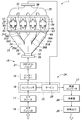
- FIG. 2 Schematic view of an internal combustion engine provided with an intake system according to the first embodiment
- a perspective view of the intake system according to the first embodiment A perspective view of the intake system according to the first embodiment
- IV-IV sectional view of FIG. 2 VV cross section of FIG. 2
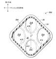
- Sectional view of an intake system according to a second embodiment Sectional view of an intake system according to a third embodiment
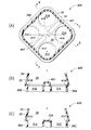
- A) Sectional view of the intake system according to the fourth embodiment (B) Sectional view along the line BB in FIG. 10 (A), (C) Section along the line CC in FIG.
- FIG. 10 (A) (A) Sectional view of the intake system according to the fifth embodiment, (B) Sectional view along the line BB in FIG. 11 (A), (C) Section along the line CC in FIG. 11 (A) (A) Top view of intake system according to the sixth embodiment, (B) BB sectional view of FIG. 12 (A) Sectional view of an intake system according to a seventh embodiment
- the internal combustion engine 1 is a four-stroke, in-line four-cylinder reciprocating engine.
- an engine body 2 which is a main body of the internal combustion engine 1 is formed by combining a cylinder block, a cylinder head, an oil pan, a head cover, and the like.
- first to fourth four cylinders 3 (3A, 3B, 3C, 3D) are formed.
- the four cylinders 3 are arranged in series such that the cylinder axes which are the respective axes are parallel to one another and arranged on one virtual plane.
- the arrangement direction of the cylinders 3A to 3D is referred to as a cylinder row direction.
- the four cylinders 3 are a first cylinder 3A, a second cylinder 3B, a third cylinder 3C, and a fourth cylinder 3D in this order from one side (left side in FIG. 1) along the cylinder row direction.
- the cylinder row direction extends in the front-rear direction, and a direction orthogonal to the cylinder row direction and the cylinder axial direction is described as the left-right direction.
- a piston (not shown) is reciprocally received, and a combustion chamber 5 is formed between the top surface of the piston and the end of the cylinder 3.
- An intake port 6 and an exhaust port 7 communicate with each combustion chamber 5.
- the intake port 6 extends from each combustion chamber 5 to a side surface of one side of the engine body 2 in the left-right direction orthogonal to the cylinder row direction and the cylinder axial direction, and the exhaust port 7 opens from the respective combustion chambers 5 in the left-right direction. It extends to the other side of the engine body 2 and is open.
- Each of the intake port 6 and the exhaust port 7 has an outer end opening to the side surface of the engine body 2 and an inner end branching into two branches and communicating with the combustion chamber 5 respectively.
- the outer ends of the intake port 6 and the exhaust port 7 extend substantially in parallel with the left-right direction.
- the configuration corresponding to the first cylinder 3A (for example, the intake port 6) is given the suffix A
- the configuration corresponding to the second cylinder 3B is given the suffix B
- the third cylinder 3C The suffix C is added to the configuration corresponding to F.
- the index D is assigned to the configuration corresponding to the fourth cylinder 3D.
- the first to fourth intake ports 6A to 6D are equal in length and volume to each other.
- the lengths of the first to fourth intake ports 6A to 6D are the distance from the inner end connected to the combustion chamber 5 to the outer end opening on the side surface of the engine body 2.
- An intake valve 11 is provided at the boundary between each of the combustion chamber 5 and the inner end of the intake port 6, and an exhaust valve 12 is provided at the boundary between each of the combustion chamber 5 and the inner end of the exhaust port 7. It is done.
- the intake valve 11 and the exhaust valve 12 are known poppet valves, and switch the communication state between the ports 6 and 7 and the combustion chamber 5 between open and close.
- the piston received in the first cylinder 3A and the piston received in the fourth cylinder 3D are in the same phase, and the first cylinder 3A and the second cylinder 3B are used.
- the received piston has a 180 ° phase difference with respect to the piston received in the first cylinder 3A.
- the firing order is the first cylinder 3A (0 °), the third cylinder 3C (180 °), the fourth cylinder 3D (360 °), and the second cylinder 3B (540 °).
- An intake system 15 of the internal combustion engine 1 includes an air inlet 16 (intake inlet), an air cleaner 17, a compressor 21 of a turbocharger 20, an intercooler 19 which is a cooling device for intake air, a throttle valve 18, and an intake device 23 Manifold), including the intake port 6.
- Each intake port 6 is provided with a fuel injection device (not shown). Air is taken in from the air inlet 16, passes through the air cleaner 17 to remove foreign matter, and the flow rate is adjusted at the throttle valve 18 and pressurized at the compressor 21. The air that has passed through the compressor 21 is distributed to the respective intake ports 6 in the intake device 23, and receives supply of fuel from the fuel injection device at the intake port 6 to form an air-fuel mixture. The air-fuel mixture passes through the intake valve 11, flows into the combustion chamber 5, and burns at a predetermined timing.
- the exhaust system 24 of the internal combustion engine 1 includes an exhaust port 7, an exhaust manifold 25, a turbine 26 of the turbocharger 20, a catalytic converter 27, a silencer 28, and an exhaust outlet 29 in this order from the upstream side.
- the exhaust gas generated by the combustion in each combustion chamber 5 is collected in the exhaust manifold 25, and after a part of energy is recovered in the turbine 26, it is purified through the catalytic converter 27. Thereafter, the exhaust gas passes through the silencer 28 and is discharged from the exhaust outlet 29 to the outside.
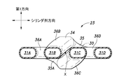
- the intake device 23 has an intake chamber 30 disposed on the upstream side, and first to fourth branch passages 31A to 31D extending downstream from the intake chamber 30.
- the introduction passage 32 is in communication with the intake chamber 30 from the upstream side.
- the first branch passage 31A communicates with the first intake port 6A corresponding to the first cylinder 3A.
- branch passages 31B to 31D of other numbers communicate with intake ports 6B to 6D of cylinders 3B to 3D of corresponding numbers.
- the introduction passage 32, the intake chamber 30, and the first to fourth branch passages 31A to 31D are formed inside the outer housing 34.
- the housing 34 has a chamber portion 35 forming the intake chamber 30, four branch pipe portions 36A to 36D projecting from the chamber portion 35 and forming the branch passages 31A to 31D, and projecting from the chamber portion 35 to form the introduction passage 32 And an introduction pipe portion 37.
- the housing 34 is formed, for example, by molding a resin.
- the chamber portion 35 is formed in a square pyramid having a square bottom plate 35A.
- An inlet pipe 37 is connected to the top of the head facing the bottom plate 35A of the chamber 35.
- An upstream flange 39 is formed on the outer peripheral portion of the upstream end of the introduction pipe portion 37. The upstream flange 39 is connected directly to the housing of the throttle valve 18 or to a pipe connected to the housing of the throttle valve 18.
- the upstream end of the four branch pipe portions 36A to 36D is connected to the bottom plate 35A of the chamber portion 35.
- first to fourth openings 41A to 41D which are through holes, are formed.
- the intake chamber 30 and the first to fourth branch passages 31A to 31D communicate with each other through the first to fourth openings 41A to 41D.
- the first to fourth openings 41A to 41D form the upstream ends of the first to fourth branch passages 31A to 31D.
- the first to fourth openings 41A to 41D are respectively formed in a circular shape, and the radius is set to be equal to each other.
- the first to fourth openings 41A to 41D are disposed around the center line X.
- the first to fourth openings 41A to 41D are formed in the first opening 41A, the first opening 41A, the fourth opening 41A, and the fourth opening 41A to 41D in the rotational direction about the center line X orthogonal to the bottom plate 35A.
- the three openings 41C, the fourth opening 41D, and the second opening 41B are arranged at equal intervals in this order.
- the order of the openings 41A to 41D is the same as the ignition order of the cylinders 3A to 3D.
- the openings 41A to 41D are arranged in the rotational direction around the center line X such that the cylinders 3A to 3D of the corresponding numbers are in the firing order.
- the center line X is arranged to coincide with the perpendicular of the square pyramid of the chamber portion 35. Further, the introduction passage 32 is arranged such that its axis coincides with the center line X. In another embodiment, the center line X may not coincide with the perpendicular of the square pyramid of the chamber portion 35, and the introduction passage 32 may not have its axis coincide with the center line X.
- the center line X is disposed on an imaginary plane orthogonal to the cylinder row direction and passing through a portion between the second and third cylinders 3B and 3C. Further, the center line X is disposed substantially in parallel with the extending direction of the outer end portions of the intake ports 6A to 6D.
- the bottom plate 35A is disposed to be orthogonal to the extending direction of the outer end of each intake port 6A to 6D.
- a pair of corner portions located at diagonal positions of the bottom plate 35A is disposed in the cylinder row direction of the center line X. Assuming that a direction perpendicular to the cylinder row direction and the center line X is a first direction (vertical direction), the remaining pair of corner portions are arranged in the first direction with respect to the center line X.
- the first to fourth openings 41A to 41D are disposed at each corner of the bottom plate 35A formed in a rectangular shape.
- the first opening 41A is disposed at a corner of the bottom plate 35A, which is disposed on the side of the first cylinder 3A in the cylinder row direction with respect to the center line X.
- the second opening 41B is disposed at a corner of the bottom plate 35A, which is disposed above the center line X in the first direction.
- the third opening 41C is disposed at a corner of the bottom plate 35A, which is disposed below in the first direction with respect to the center line X.
- the fourth opening 41D is disposed at a corner of the bottom plate 35A, which is disposed on the fourth cylinder 3D side in the cylinder row direction with respect to the center line X.
- the first branch pipe portion 36A extends from the first opening 41A to the outside in the cylinder row direction with respect to the center line X (in a direction away from the center line X and on the side of the first cylinder 3A). ing.
- the fourth branch pipe portion 36D extends obliquely from the fourth opening 41D outward in the cylinder row direction with respect to the center line X (in a direction away from the center line X and on the fourth cylinder 3D side) ing.
- the first branch pipe portion 36A and the fourth branch pipe portion 36D are formed symmetrically with respect to a virtual plane orthogonal to the cylinder row direction and including the center line X.
- the second branch pipe portion 36B extends from the second opening 41B in parallel to the center line X, and then the center line X side in the first direction and the outer side in the cylinder row direction (the direction away from the center line X , And extends obliquely to the first cylinder 3A side).
- the downstream end of the second branch pipe portion 36B is disposed inward (in the direction approaching the center line X) in the cylinder row direction of the downstream end of the first branch pipe portion 36A.
- the third branch pipe portion 36C extends from the third opening 41C in parallel to the center line X, and then the center line X side in the first direction and the outer side in the cylinder row direction (the direction away from the center line X , And extends obliquely to the fourth cylinder 3D side).
- the downstream end of the third branch pipe portion 36C is disposed inward (in the direction approaching the center line X) in the cylinder row direction of the downstream end of the fourth branch pipe portion 36D.
- the downstream ends of the first to fourth branch pipe portions 36A to 36D are arranged in a line in the cylinder row direction and open in a direction parallel to the center line X.
- the downstream ends of the first to fourth branch pipe portions 36A to 36D are a first branch pipe portion 36A, a second branch pipe portion 36B, a third branch pipe portion 36C, and a fourth branch pipe portion along the cylinder row direction. It arranges in order of branch pipe part 36D.
- the downstream ends of the first to fourth branch pipe portions 36A to 36D are connected to each other by one downstream flange 43.
- the first to fourth branch passages 31A to 31D are formed inside the first to fourth branch pipe portions 36A to 36D along the respective branch pipe portions 36A to 36D.
- the cross sections of the first to fourth branch passages 31A to 31D are formed in a circular shape, and the radius is set to be equal to each other.
- the first to fourth branch passages 31A to 31D are equal in length and volume to each other.
- the downstream flange 43 is coupled to the side surface of the engine body 2. Thereby, the downstream end of the first branch passage 31A is connected to the first intake port 6A, the downstream end of the second branch passage 31B is connected to the second intake port 6B, and the third branch passage 31C The downstream end is connected to the third intake port 6C, and the downstream end of the fourth branch passage 31D is connected to the fourth intake port 6D.
- the first to fourth cylinders 3A to 3D of the internal combustion engine 1 have an intake stroke during two rotations (720.degree. Rotation) of the crankshaft based on the Atkinson cycle (mirror cycle).
- the blow back stroke, the compression stroke, the expansion stroke, and the exhaust stroke are sequentially performed.
- the blow back stroke may be recognized as part of the intake stroke.
- the intake valve 11 is opened and the exhaust valve 12 is closed, whereby the air-fuel mixture is taken in from the intake port 6 (intake stroke).
- the pistons of the first and fourth cylinders 3A and 3D are at the top dead center when the crank angle is 0 ° and 360 °, and the pistons of the second and third cylinders 3C have a crank angle of 180 ° and 540 It is at top dead center at the time of °.
- the firing order is the order of the first cylinder 3A, the third cylinder 3C, the fourth cylinder 3D, and the second cylinder 3B.
- the third cylinder 3C has a phase of 180 with respect to the first cylinder 3A.
- the fourth cylinder 3D is delayed in phase by 360 °
- the fourth cylinder 3D is delayed in phase by 540 °.
- the first to fourth openings 41A to 41D that form the connection portions of the first to fourth branch passages 31A to 31D with the intake chamber 30 are rotated in the rotational direction about the center line X. They are arranged in the same order as the firing order of the first to fourth cylinders 3A to 3D. Therefore, the opening 41 corresponding to the cylinder 3 in the intake stroke and the opening 41 corresponding to the cylinder 3 in the blow-back stroke are always adjacent in the rotational direction around the center line X.
- the lengths and volumes of the first to fourth intake ports 6A to 6D are equal to one another, and the lengths and volumes of the first to fourth branch passages 31A to 31D are equal to one another.
- the distance and volume from the four cylinders 3A to 3D to the intake chamber 30 via the intake ports 6A to 6D and the branch passages 31A to 31D are equal to one another. Therefore, regardless of which cylinder 3 is in the intake stroke, the intake port 6, branch passage 31, intake chamber 30, branch passage 31, intake port 6 of the cylinder 3 in the intake stroke and the cylinder 3 in the return stroke. The distance and volume through the Therefore, the influence of blow back on the cylinders 3 in the intake stroke becomes equal among the cylinders 3A to 3D, and the difference in air-fuel ratio among the cylinders 3A to 3D decreases.
- FIG. 7 is a diagram comparing the difference in air-fuel ratio of each of the cylinders 3A to 3D in the intake system 23 according to the first embodiment with the difference in air-fuel ratio of the intake system according to the comparative example.
- the difference between the air-fuel ratios of the cylinders 3A to 3D means the difference between the air-fuel ratio of the cylinder whose air-fuel ratio is the largest among the four cylinders 3A to 3D and the air-fuel ratio of the cylinders It is.
- the intake system according to the comparative example is the same as the intake system 23 according to the first embodiment, except that the position where the upstream end of the branch passage is connected to the intake chamber is different.
- the upstream end of the first branch passage is connected to the position corresponding to the first opening 41A of the intake system 23 according to the first embodiment, and the upstream end of the second branch passage is the first embodiment
- the upstream end of the third branch passage is connected to a position corresponding to the fourth opening 41D of the intake device 23 according to the first embodiment, which is connected to the position corresponding to the second opening 41B of the intake device 23 according to the embodiment.
- the upstream end of the fourth branch passage is connected to a position corresponding to the third opening 41C of the intake device 23 according to the first embodiment.
- each of the upstream ends of the branch passages is the same as the ignition order (first, third, fourth, second) of the cylinder 3 in the rotational direction about the center line X They are not arranged in order, but are arranged in the same order as the arrangement order (first, second, third, fourth) of the cylinders 3.
- the lengths of the branch passages are set to be equal to each other.
- the ignition order is the first cylinder 3A, the third cylinder 3C, the fourth cylinder 3D, and the second cylinder 3B in this order.
- the upstream end of the branch passage 31 corresponding to the cylinder 3 in the intake stroke and the upstream end of the branch passage 31 corresponding to the cylinder 3 in the return stroke when the cylinder 3 in the intake stroke is replaced, the upstream end of the branch passage 31 corresponding to the cylinder 3 in the intake stroke and the upstream end of the branch passage 31 corresponding to the cylinder 3 in the return stroke.
- the third cylinder 3C when the third cylinder 3C is in the intake stroke, the first cylinder 3A is in the reverse stroke, and the upstream end of the first branch passage 31A and the upstream end of the third branch passage 31C are parallel to the center line X They are not adjacent to each other in the center of rotation direction. Therefore, if the cylinder 3 in the intake stroke alternates in distance between the cylinder 3 in the intake stroke and the cylinder 3 in the blowback stroke via the intake port 6, branch passage, intake chamber 30, branch passage, and intake port 6 Change.
- the intake device 23 according to the present embodiment can reduce the difference in air-fuel ratio among the cylinders 3A to 3D without increasing the volume (length) of the branch passage 31.
- the intake device 23 can be miniaturized. Further, in the intake system 23 according to the present embodiment, since the volume (length) of the branch passage 31 can be reduced, the time taken for the operation of the throttle valve 18 or the turbocharger 20 to appear as a change in the intake amount is short. can do.
- each branch passage 31 has its upstream end offset (biased) to the inside in the cylinder row direction (center line X side) with respect to the downstream end. Therefore, the blowback flow passing through any cross section of each branch passage 31 has a high velocity (density) at the outer side in the cylinder row direction and a low velocity (density) at the inner side. That is, the blowback flow passing through any cross section of each branch passage 31 has a speed difference (density difference) in the cylinder row direction due to the shape of the branch passage 31.
- the inward offset amount (length in the cylinder row direction of the branch passages 31A, 31D) of the first and fourth branch passages 31A, 31D with respect to the downstream end with respect to the downstream end is the second and third branches. Since it is larger than the offset amount to the center side in the cylinder row direction of the upstream end with respect to the downstream end in the passages 31B and 31C, the first and fourth branch passages 31A and 31D are more than the second and third branch passages 31B and 31C.
- the velocity difference (density difference) increases in the cylinder row direction of the backflow.
- the distance from the first or fourth opening 41A, 41D is more than the distance when the backflow flows from the second or third opening 41B, 41C to the first or fourth opening 41A, 41D.
- the distance when the backflow flows through the second or third opening 41B, 41C becomes longer, and the backflow becomes difficult to flow.
- the flow from the first opening 41A to the third opening 41C and the flow from the fourth opening 41D to the second opening 41B are the flow from the third opening 41C to the fourth opening 41D. This makes it harder to flow than the flow from the second opening 41B to the first opening 41A.
- the cylinder row direction of the blowback flow in the above-mentioned branch passage 31 is obtained by changing a part of the intake device 23 according to the first embodiment. It is an object of the present invention to further reduce the difference in air-fuel ratio of each of the cylinders 3A to 3D due to the speed difference in the above.
- the same components as those of the first embodiment are denoted by the same reference numerals and descriptions thereof will be omitted, and only different components will be described.
- the second opening 41 B is the fourth with respect to the center line X in the cylinder row direction.
- the third opening 41C is offset to the first opening 41A side with respect to the center line X in the cylinder row direction.
- the distance between the first opening 41A and the third opening 41C and the distance between the second opening 41B and the fourth opening 41D are set equal, and the first opening 41A and the second opening The distance to the opening 41B and the distance between the third opening 41C and the fourth opening 41D are set equal.
- the bottom plate 35A is rectangular, the first opening 41A and the second opening 41B are disposed along one of the long sides, and the third opening 41C and the fourth opening 41D are the other of the long sides. Placed along the
- the intake system 200 according to the second embodiment compared to the intake system 23 according to the first embodiment, the flow from the first opening 41A to the third opening 41C and the fourth opening 41D to the second The flow to the opening 41B is promoted, and the flow from the third opening 41C to the fourth opening 41D and the flow from the second opening 41B to the first opening 41A are suppressed.
- the difference in air-fuel ratio among the cylinders 3A to 3D generated in the intake system 23 according to the first embodiment can be further reduced.
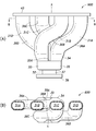
- the first to fourth branch passages 31A to 31D and the first to fourth openings 41A to 41D have transverse sections in the first direction.
- the length is formed in an elliptical shape longer than the length in the cylinder row direction.
- the intake system 300 according to the third embodiment as compared with the intake system 23 according to the first embodiment, crossing of the first to fourth branch passages 31A to 31D and the first to fourth openings 41A to 41D Since the width of the surface in the cylinder row direction is reduced, the speed difference (density difference) in the cylinder row direction of the backflow in the first to fourth openings 41A to 41D is reduced. Thereby, the distance when the blow back flow flows from the second or third opening 41B, 41C to the first or fourth opening 41A, 41D, and the second or fourth from the first or fourth opening 41A, 41D The difference with the distance when flowing through the three openings 41B and 41C is reduced.
- the intake system 300 according to the third embodiment can further reduce the difference in air-fuel ratio among the cylinders 3A to 3D generated in the intake system 23 according to the first embodiment.
- the first opening 41A and the second opening 41A are the inner surface (surface on the intake chamber 30 side) of the bottom plate 35A.
- a first barrier 401 is provided protruding from a portion between the opening 41B and a second barrier 402 is provided protruding from a portion between the third opening 41C and the fourth opening 41D.
- the first barrier 401 extends from the edge of the bottom plate 35A toward the center line X so as to separate the portion where the first opening 41A is provided and the portion where the second opening 41B is provided.
- the second barrier 402 extends from the edge of the bottom plate 35A toward the center line X so as to separate the portion where the third opening 41C is provided and the portion where the fourth opening 41D is provided. doing.
- the intake system 400 according to the fourth embodiment compared with the intake system 23 according to the first embodiment, the backflow from the second opening 41B to the first opening 41A is suppressed by the first barrier 401, The second barrier 402 suppresses backflow from the third opening 41C to the fourth opening 41D.
- the intake system 400 according to the fourth embodiment can further reduce the difference in air-fuel ratio among the cylinders 3A to 3D generated in the intake system 23 according to the first embodiment.
- the first opening 41A and the third opening 41A are the inner surface (the surface on the intake chamber 30 side) of the bottom plate 35A.
- a first curved surface portion 501 is formed in a portion between the opening 41C and a second curved surface portion 502 is formed in a portion between the third opening 41C and the fourth opening 41D.
- the first curved surface portion 501 is formed to smoothly connect the edge of the first opening 41A and the edge of the third opening 41C.
- the first curved surface portion 501 is a corner (an edge of the first opening 41A) formed by the inner surface of the bottom plate 35A and the inner surface of the first branch pipe portion 36A, and the inner surface of the bottom plate 35A
- the corner portion (the edge portion of the second opening 41B) formed by the inner surface of the second branch pipe portion 36B is chamfered.
- the second curved surface portion 502 is formed to smoothly connect the edge of the third opening 41C and the edge of the fourth opening 41D.
- the external shape of the cross section of the first and second curved surface portions 501 and 502 is formed in an arc shape such as a semicircle.
- the first curved surface portion 501 promotes the blowback flow from the first opening 41A to the third opening 41C.
- the second curved surface portion 502 promotes a backflow from the fourth opening 41D to the second opening 41B.
- the intake system 500 according to the fifth embodiment can further reduce the difference in air-fuel ratio among the cylinders 3A to 3D generated in the intake system 23 according to the first embodiment.
- the intake system 600 according to the sixth embodiment differs from the intake system 23 according to the first embodiment in the arrangement of the first to fourth openings 41A to 41D.
- the first opening 41A is on the first cylinder 3A side in the cylinder row direction with respect to the center line X, and It is disposed above in the first direction.
- the second opening 41B is disposed on the fourth cylinder 3D side in the cylinder row direction with respect to the center line X and above in the first direction, and the fourth cylinder in the cylinder row direction with respect to the first opening 41A. It is arranged on the 3D side.
- the third opening 41C is disposed on the first cylinder 3A side in the cylinder row direction with respect to the center line X and downward in the first direction, and is disposed downward in the first direction with respect to the first opening 41A.
- the fourth opening 41D is disposed on the fourth cylinder 3D side in the cylinder row direction with respect to the center line X and downward in the first direction, and the fourth cylinder 41 in the cylinder row direction with respect to the third opening 41C. It is arranged on the 3D side.
- the offset amount in the cylinder row direction with respect to the center line X of the second opening 41B and the third opening 41C is the center line X of the first opening 41A and the fourth opening 41D.
- the offset amount in the cylinder row direction with respect to Therefore, in the intake system 600 according to the sixth embodiment, compared to the intake system 23 according to the first embodiment, the lengths of the second branch passage 31B and the third branch passage 31C in the cylinder row direction and the The difference between the length of the first branch passage 31A and the length of the fourth branch passage 31D in the cylinder row direction is reduced.
- An intake system 700 according to the seventh embodiment is a system in which the manufacturability of the intake system 23 according to the first embodiment is enhanced.
- the second branch pipe portion 36B and the third branch pipe portion 36C overlap each other in the first direction (vertical direction), and there is a gap between them, and the cylinder row is formed.
- the first to fourth branch pipe portions 36A to 36D respectively overlap each other, and there is an air gap between the respective branch pipe portions 36A to 36D. Therefore, the outer shape of the intake device 23 can not be molded using a two-divided mold.
- An intake system 700 according to the seventh embodiment is configured to allow the outer shape of the intake system 23 to be molded using a two-piece mold.
- the outer surfaces of the first to fourth branch pipe portions 36A to 36D and the outer surface of the chamber portion 35 are connected to each other by a connecting wall 701.
- the outer surfaces of the first to fourth branch pipe portions 36A to 36D, the outer surface of the chamber portion 35, and the connection wall 701 form an inner chamber 702 closed to the outside of the intake device 700.
- the inner chamber 702 is in communication with the intake chamber 30 through a through hole 703 formed in the central portion of the bottom plate 35A.
- the present invention can be widely modified and implemented without being limited to the above embodiment.
- an example of the intake system 23, 200, 300, 400, 500, 600 corresponding to the four-cylinder internal combustion engine 1 is shown.
- the intake system 23, 200, 300, 400, 500, 600 has three cylinders.
- the present invention can be applied to the internal combustion engine 1 described above.
- the intake system 23 has a configuration in which the second and third openings 41C according to the second embodiment are offset in the cylinder row direction with respect to the center line X, and the cross sections of each branch passage 31 and the opening 41 according to the third embodiment. At least two of the configuration to make it elliptical, the configuration to provide the first and second barriers 401 and 402 according to the fourth embodiment, and the configuration to provide the first and second curved surface portions 501 and 502 according to the fifth embodiment. You may have one.
- the ignition orders are the first, second, fourth, and third orders. It is also good. Also in this case, each of the upstream ends (first to fourth openings 41A to 41D) of the first to fourth branch passages 31A to 31D is rotated about the center line X, as in the above embodiment. In the direction, the ignition sequence of the first to fourth cylinders 3A to 3D is arranged in the same order, and the same effect is obtained.
- each branch pipe part 36A, 36B, 36C, 36D in said embodiment are an illustration, and are not limited to the example described.
- the second branch pipe portion 36B and the third branch pipe portion 36C have portions extending parallel to the center line X from the second opening 41B and the third opening 41C.
- the configuration is not essential and can be replaced with other shapes.
- the configuration of the intake system 15 is not limited to that shown in FIG.
- the intake system 15 may be provided with an exhaust gas recirculation passage that recirculates the exhaust gas to the intake system 15.
- the exhaust gas recirculation passage may be provided to connect, for example, the exhaust manifold 25 and the intake chamber 30 of the intake device 23.
- a cooling device may be provided to cool the exhaust gas returned to the intake device 23.
- the intercooler 19 may be incorporated in the intake device 23.
Landscapes
- Engineering & Computer Science (AREA)
- Chemical & Material Sciences (AREA)
- Combustion & Propulsion (AREA)
- Mechanical Engineering (AREA)
- General Engineering & Computer Science (AREA)
- Lubrication Details And Ventilation Of Internal Combustion Engines (AREA)
- Cylinder Crankcases Of Internal Combustion Engines (AREA)
- Exhaust Gas After Treatment (AREA)
Abstract
Priority Applications (3)
| Application Number | Priority Date | Filing Date | Title |
|---|---|---|---|
| US15/308,416 US10260462B2 (en) | 2014-07-01 | 2015-03-24 | Intake device |
| CN201580035138.8A CN106662050B (zh) | 2014-07-01 | 2015-03-24 | 进气装置 |
| JP2016530805A JP6182674B2 (ja) | 2014-07-01 | 2015-03-24 | 吸気装置 |
Applications Claiming Priority (2)
| Application Number | Priority Date | Filing Date | Title |
|---|---|---|---|
| JP2014135519 | 2014-07-01 | ||
| JP2014-135519 | 2014-07-01 |
Publications (1)
| Publication Number | Publication Date |
|---|---|
| WO2016002112A1 true WO2016002112A1 (fr) | 2016-01-07 |
Family
ID=55018696
Family Applications (1)
| Application Number | Title | Priority Date | Filing Date |
|---|---|---|---|
| PCT/JP2015/001661 Ceased WO2016002112A1 (fr) | 2014-07-01 | 2015-03-24 | Dispositif d'admission |
Country Status (4)
| Country | Link |
|---|---|
| US (1) | US10260462B2 (fr) |
| JP (1) | JP6182674B2 (fr) |
| CN (1) | CN106662050B (fr) |
| WO (1) | WO2016002112A1 (fr) |
Citations (6)
| Publication number | Priority date | Publication date | Assignee | Title |
|---|---|---|---|---|
| JPS57101367U (fr) * | 1980-12-15 | 1982-06-22 | ||
| JPS63170568U (fr) * | 1987-04-28 | 1988-11-07 | ||
| DE3728179A1 (de) * | 1987-08-24 | 1989-03-09 | Opel Adam Ag | Brennkraftmaschine |
| JPH01208511A (ja) * | 1988-02-15 | 1989-08-22 | Nissan Motor Co Ltd | 多気筒内燃機関の吸気装置 |
| JPH04136420A (ja) * | 1990-09-28 | 1992-05-11 | Mazda Motor Corp | エンジンの吸気装置 |
| JP2008501082A (ja) * | 2004-06-01 | 2008-01-17 | ウェッセルス ステファン | 流体分配マニフォールド |
Family Cites Families (9)
| Publication number | Priority date | Publication date | Assignee | Title |
|---|---|---|---|---|
| US3024774A (en) * | 1959-02-05 | 1962-03-13 | Int Harvester Co | Tuned intake manifold |
| US4765285A (en) * | 1985-08-07 | 1988-08-23 | Yamaha Hatsudoki Kabushiki Kaisha | Intake system for internal combustion engine |
| US4664075A (en) * | 1985-10-30 | 1987-05-12 | General Motors Corporation | Symmetric manifold |
| JPH0791983B2 (ja) | 1989-09-05 | 1995-10-09 | マツダ株式会社 | 多気筒エンジンの吸気装置 |
| JPH0484756U (fr) | 1990-11-29 | 1992-07-23 | ||
| US5947483A (en) * | 1993-12-10 | 1999-09-07 | Firma Carl Freudenberg | Seal for the gas-tight mounting of an intake manifold on the cylinder head of an internal combustion engine |
| JPH10196474A (ja) * | 1997-01-14 | 1998-07-28 | Daihatsu Motor Co Ltd | インテークマニホールド |
| JP4103424B2 (ja) * | 2002-03-28 | 2008-06-18 | アイシン精機株式会社 | エンジンの吸気装置 |
| JP5917908B2 (ja) * | 2011-12-27 | 2016-05-18 | 株式会社マーレ フィルターシステムズ | 吸気流制御弁 |
-
2015
- 2015-03-24 US US15/308,416 patent/US10260462B2/en active Active
- 2015-03-24 WO PCT/JP2015/001661 patent/WO2016002112A1/fr not_active Ceased
- 2015-03-24 JP JP2016530805A patent/JP6182674B2/ja not_active Expired - Fee Related
- 2015-03-24 CN CN201580035138.8A patent/CN106662050B/zh not_active Expired - Fee Related
Patent Citations (6)
| Publication number | Priority date | Publication date | Assignee | Title |
|---|---|---|---|---|
| JPS57101367U (fr) * | 1980-12-15 | 1982-06-22 | ||
| JPS63170568U (fr) * | 1987-04-28 | 1988-11-07 | ||
| DE3728179A1 (de) * | 1987-08-24 | 1989-03-09 | Opel Adam Ag | Brennkraftmaschine |
| JPH01208511A (ja) * | 1988-02-15 | 1989-08-22 | Nissan Motor Co Ltd | 多気筒内燃機関の吸気装置 |
| JPH04136420A (ja) * | 1990-09-28 | 1992-05-11 | Mazda Motor Corp | エンジンの吸気装置 |
| JP2008501082A (ja) * | 2004-06-01 | 2008-01-17 | ウェッセルス ステファン | 流体分配マニフォールド |
Also Published As
| Publication number | Publication date |
|---|---|
| CN106662050B (zh) | 2019-05-14 |
| US20170122271A1 (en) | 2017-05-04 |
| CN106662050A (zh) | 2017-05-10 |
| JPWO2016002112A1 (ja) | 2017-04-27 |
| JP6182674B2 (ja) | 2017-08-16 |
| US10260462B2 (en) | 2019-04-16 |
Similar Documents
| Publication | Publication Date | Title |
|---|---|---|
| US9038612B2 (en) | Exhaust gas recirculation device of multi-cylinder engine | |
| US10598074B2 (en) | Exhaust device of multiple-cylinder engine | |
| JP2021004569A (ja) | Egrガス分配装置 | |
| US9140198B2 (en) | Intake and exhaust apparatus of multi-cylinder engine | |
| JP6182674B2 (ja) | 吸気装置 | |
| RU2699856C2 (ru) | Система сгорания для двигателя (варианты) и головка блока цилиндров для использования в этой системе | |
| JP7112290B2 (ja) | タンブル流生成装置 | |
| EP1947320B1 (fr) | Système de reccirculation des gaz d'échappement d'un moteur à combustion interne multicylindre | |
| US20200049110A1 (en) | Air intake system for multi-cylinder engine | |
| JP2010031688A (ja) | 火花点火式内燃機関 | |
| JP2018173014A (ja) | 多気筒エンジンの吸気装置 | |
| US7444974B2 (en) | Internal combustion engine intake device | |
| JP2010031687A (ja) | 火花点火式内燃機関 | |
| JP6258653B2 (ja) | 内燃機関 | |
| JP6258654B2 (ja) | 内燃機関 | |
| JP7365583B2 (ja) | 多気筒エンジンの吸気装置 | |
| JP4860451B2 (ja) | 内燃機関 | |
| JP2013024171A (ja) | 内燃機関 | |
| CN101874153A (zh) | 多缸内燃机的进气装置 | |
| JP2013241834A (ja) | 内燃機関の排気還流装置 | |
| JP2012036805A (ja) | 熱交換部材、および、それを用いた吸気システム | |
| JP2010031686A (ja) | 火花点火式内燃機関 | |
| JP6032802B2 (ja) | Egr装置 | |
| JP2002317702A (ja) | 直列多気筒内燃機関 | |
| JP6299797B2 (ja) | エンジンの排気装置 |
Legal Events
| Date | Code | Title | Description |
|---|---|---|---|
| 121 | Ep: the epo has been informed by wipo that ep was designated in this application |
Ref document number: 15816033 Country of ref document: EP Kind code of ref document: A1 |
|
| ENP | Entry into the national phase |
Ref document number: 2016530805 Country of ref document: JP Kind code of ref document: A |
|
| WWE | Wipo information: entry into national phase |
Ref document number: 15308416 Country of ref document: US |
|
| NENP | Non-entry into the national phase |
Ref country code: DE |
|
| 122 | Ep: pct application non-entry in european phase |
Ref document number: 15816033 Country of ref document: EP Kind code of ref document: A1 |