WO2016002424A1 - Dispositif d'affichage à cristaux liquides - Google Patents
Dispositif d'affichage à cristaux liquides Download PDFInfo
- Publication number
- WO2016002424A1 WO2016002424A1 PCT/JP2015/066144 JP2015066144W WO2016002424A1 WO 2016002424 A1 WO2016002424 A1 WO 2016002424A1 JP 2015066144 W JP2015066144 W JP 2015066144W WO 2016002424 A1 WO2016002424 A1 WO 2016002424A1
- Authority
- WO
- WIPO (PCT)
- Prior art keywords
- information
- transparent
- liquid crystal
- blanking period
- display device
- Prior art date
- Legal status (The legal status is an assumption and is not a legal conclusion. Google has not performed a legal analysis and makes no representation as to the accuracy of the status listed.)
- Ceased
Links
Images





Classifications
-
- H—ELECTRICITY
- H04—ELECTRIC COMMUNICATION TECHNIQUE
- H04N—PICTORIAL COMMUNICATION, e.g. TELEVISION
- H04N5/00—Details of television systems
- H04N5/44—Receiver circuitry for the reception of television signals according to analogue transmission standards
- H04N5/445—Receiver circuitry for the reception of television signals according to analogue transmission standards for displaying additional information
- H04N5/44504—Circuit details of the additional information generator, e.g. details of the character or graphics signal generator, overlay mixing circuits
-
- G—PHYSICS
- G09—EDUCATION; CRYPTOGRAPHY; DISPLAY; ADVERTISING; SEALS
- G09G—ARRANGEMENTS OR CIRCUITS FOR CONTROL OF INDICATING DEVICES USING STATIC MEANS TO PRESENT VARIABLE INFORMATION
- G09G3/00—Control arrangements or circuits, of interest only in connection with visual indicators other than cathode-ray tubes
- G09G3/20—Control arrangements or circuits, of interest only in connection with visual indicators other than cathode-ray tubes for presentation of an assembly of a number of characters, e.g. a page, by composing the assembly by combination of individual elements arranged in a matrix no fixed position being assigned to or needed to be assigned to the individual characters or partial characters
- G09G3/2003—Display of colours
-
- G—PHYSICS
- G09—EDUCATION; CRYPTOGRAPHY; DISPLAY; ADVERTISING; SEALS
- G09G—ARRANGEMENTS OR CIRCUITS FOR CONTROL OF INDICATING DEVICES USING STATIC MEANS TO PRESENT VARIABLE INFORMATION
- G09G3/00—Control arrangements or circuits, of interest only in connection with visual indicators other than cathode-ray tubes
- G09G3/20—Control arrangements or circuits, of interest only in connection with visual indicators other than cathode-ray tubes for presentation of an assembly of a number of characters, e.g. a page, by composing the assembly by combination of individual elements arranged in a matrix no fixed position being assigned to or needed to be assigned to the individual characters or partial characters
- G09G3/34—Control arrangements or circuits, of interest only in connection with visual indicators other than cathode-ray tubes for presentation of an assembly of a number of characters, e.g. a page, by composing the assembly by combination of individual elements arranged in a matrix no fixed position being assigned to or needed to be assigned to the individual characters or partial characters by control of light from an independent source
- G09G3/3406—Control of illumination source
- G09G3/3413—Details of control of colour illumination sources
-
- G—PHYSICS
- G09—EDUCATION; CRYPTOGRAPHY; DISPLAY; ADVERTISING; SEALS
- G09G—ARRANGEMENTS OR CIRCUITS FOR CONTROL OF INDICATING DEVICES USING STATIC MEANS TO PRESENT VARIABLE INFORMATION
- G09G3/00—Control arrangements or circuits, of interest only in connection with visual indicators other than cathode-ray tubes
- G09G3/20—Control arrangements or circuits, of interest only in connection with visual indicators other than cathode-ray tubes for presentation of an assembly of a number of characters, e.g. a page, by composing the assembly by combination of individual elements arranged in a matrix no fixed position being assigned to or needed to be assigned to the individual characters or partial characters
- G09G3/34—Control arrangements or circuits, of interest only in connection with visual indicators other than cathode-ray tubes for presentation of an assembly of a number of characters, e.g. a page, by composing the assembly by combination of individual elements arranged in a matrix no fixed position being assigned to or needed to be assigned to the individual characters or partial characters by control of light from an independent source
- G09G3/36—Control arrangements or circuits, of interest only in connection with visual indicators other than cathode-ray tubes for presentation of an assembly of a number of characters, e.g. a page, by composing the assembly by combination of individual elements arranged in a matrix no fixed position being assigned to or needed to be assigned to the individual characters or partial characters by control of light from an independent source using liquid crystals
- G09G3/3607—Control arrangements or circuits, of interest only in connection with visual indicators other than cathode-ray tubes for presentation of an assembly of a number of characters, e.g. a page, by composing the assembly by combination of individual elements arranged in a matrix no fixed position being assigned to or needed to be assigned to the individual characters or partial characters by control of light from an independent source using liquid crystals for displaying colours or for displaying grey scales with a specific pixel layout, e.g. using sub-pixels
-
- G—PHYSICS
- G09—EDUCATION; CRYPTOGRAPHY; DISPLAY; ADVERTISING; SEALS
- G09G—ARRANGEMENTS OR CIRCUITS FOR CONTROL OF INDICATING DEVICES USING STATIC MEANS TO PRESENT VARIABLE INFORMATION
- G09G3/00—Control arrangements or circuits, of interest only in connection with visual indicators other than cathode-ray tubes
- G09G3/20—Control arrangements or circuits, of interest only in connection with visual indicators other than cathode-ray tubes for presentation of an assembly of a number of characters, e.g. a page, by composing the assembly by combination of individual elements arranged in a matrix no fixed position being assigned to or needed to be assigned to the individual characters or partial characters
- G09G3/34—Control arrangements or circuits, of interest only in connection with visual indicators other than cathode-ray tubes for presentation of an assembly of a number of characters, e.g. a page, by composing the assembly by combination of individual elements arranged in a matrix no fixed position being assigned to or needed to be assigned to the individual characters or partial characters by control of light from an independent source
- G09G3/36—Control arrangements or circuits, of interest only in connection with visual indicators other than cathode-ray tubes for presentation of an assembly of a number of characters, e.g. a page, by composing the assembly by combination of individual elements arranged in a matrix no fixed position being assigned to or needed to be assigned to the individual characters or partial characters by control of light from an independent source using liquid crystals
- G09G3/3611—Control of matrices with row and column drivers
- G09G3/3648—Control of matrices with row and column drivers using an active matrix
-
- H—ELECTRICITY
- H04—ELECTRIC COMMUNICATION TECHNIQUE
- H04N—PICTORIAL COMMUNICATION, e.g. TELEVISION
- H04N5/00—Details of television systems
- H04N5/44—Receiver circuitry for the reception of television signals according to analogue transmission standards
- H04N5/57—Control of contrast or brightness
-
- H—ELECTRICITY
- H04—ELECTRIC COMMUNICATION TECHNIQUE
- H04N—PICTORIAL COMMUNICATION, e.g. TELEVISION
- H04N7/00—Television systems
- H04N7/08—Systems for the simultaneous or sequential transmission of more than one television signal, e.g. additional information signals, the signals occupying wholly or partially the same frequency band, e.g. by time division
- H04N7/087—Systems for the simultaneous or sequential transmission of more than one television signal, e.g. additional information signals, the signals occupying wholly or partially the same frequency band, e.g. by time division with signal insertion during the vertical blanking interval only
-
- G—PHYSICS
- G09—EDUCATION; CRYPTOGRAPHY; DISPLAY; ADVERTISING; SEALS
- G09G—ARRANGEMENTS OR CIRCUITS FOR CONTROL OF INDICATING DEVICES USING STATIC MEANS TO PRESENT VARIABLE INFORMATION
- G09G2310/00—Command of the display device
- G09G2310/02—Addressing, scanning or driving the display screen or processing steps related thereto
- G09G2310/0232—Special driving of display border areas
-
- G—PHYSICS
- G09—EDUCATION; CRYPTOGRAPHY; DISPLAY; ADVERTISING; SEALS
- G09G—ARRANGEMENTS OR CIRCUITS FOR CONTROL OF INDICATING DEVICES USING STATIC MEANS TO PRESENT VARIABLE INFORMATION
- G09G2310/00—Command of the display device
- G09G2310/02—Addressing, scanning or driving the display screen or processing steps related thereto
- G09G2310/0235—Field-sequential colour display
-
- G—PHYSICS
- G09—EDUCATION; CRYPTOGRAPHY; DISPLAY; ADVERTISING; SEALS
- G09G—ARRANGEMENTS OR CIRCUITS FOR CONTROL OF INDICATING DEVICES USING STATIC MEANS TO PRESENT VARIABLE INFORMATION
- G09G2310/00—Command of the display device
- G09G2310/06—Details of flat display driving waveforms
- G09G2310/061—Details of flat display driving waveforms for resetting or blanking
-
- G—PHYSICS
- G09—EDUCATION; CRYPTOGRAPHY; DISPLAY; ADVERTISING; SEALS
- G09G—ARRANGEMENTS OR CIRCUITS FOR CONTROL OF INDICATING DEVICES USING STATIC MEANS TO PRESENT VARIABLE INFORMATION
- G09G2320/00—Control of display operating conditions
- G09G2320/02—Improving the quality of display appearance
- G09G2320/0242—Compensation of deficiencies in the appearance of colours
-
- G—PHYSICS
- G09—EDUCATION; CRYPTOGRAPHY; DISPLAY; ADVERTISING; SEALS
- G09G—ARRANGEMENTS OR CIRCUITS FOR CONTROL OF INDICATING DEVICES USING STATIC MEANS TO PRESENT VARIABLE INFORMATION
- G09G2340/00—Aspects of display data processing
- G09G2340/12—Overlay of images, i.e. displayed pixel being the result of switching between the corresponding input pixels
-
- G—PHYSICS
- G09—EDUCATION; CRYPTOGRAPHY; DISPLAY; ADVERTISING; SEALS
- G09G—ARRANGEMENTS OR CIRCUITS FOR CONTROL OF INDICATING DEVICES USING STATIC MEANS TO PRESENT VARIABLE INFORMATION
- G09G2370/00—Aspects of data communication
- G09G2370/04—Exchange of auxiliary data, i.e. other than image data, between monitor and graphics controller
-
- G—PHYSICS
- G09—EDUCATION; CRYPTOGRAPHY; DISPLAY; ADVERTISING; SEALS
- G09G—ARRANGEMENTS OR CIRCUITS FOR CONTROL OF INDICATING DEVICES USING STATIC MEANS TO PRESENT VARIABLE INFORMATION
- G09G3/00—Control arrangements or circuits, of interest only in connection with visual indicators other than cathode-ray tubes
- G09G3/20—Control arrangements or circuits, of interest only in connection with visual indicators other than cathode-ray tubes for presentation of an assembly of a number of characters, e.g. a page, by composing the assembly by combination of individual elements arranged in a matrix no fixed position being assigned to or needed to be assigned to the individual characters or partial characters
- G09G3/2092—Details of a display terminals using a flat panel, the details relating to the control arrangement of the display terminal and to the interfaces thereto
Definitions
- the present invention relates to a liquid crystal display device, and more particularly to a liquid crystal display device that performs color display using a field sequential method or a color filter method.
- liquid crystal display devices that perform color display include color filters that transmit red (R), green (G), and blue (B) light, respectively, corresponding to subpixels obtained by dividing one pixel into three. ing.
- RGB red
- G green
- B blue
- the color filter type liquid crystal display device since about 2/3 of the backlight light applied to the liquid crystal display panel is absorbed by the color filter, the color filter type liquid crystal display device has a problem that the light use efficiency is low. Therefore, a field sequential type liquid crystal display device that performs color display without using a color filter has attracted attention.
- one frame period that is a display period of one screen is divided into three subframe periods.
- a red screen is displayed by causing the red light source to emit light while inputting the red component of the video signal.
- a green screen is displayed by causing the green light source to emit light while inputting the green component of the video signal.
- a blue screen is displayed by emitting a blue light source while inputting a blue component of a video signal.
- the field sequential type liquid crystal display device sequentially displays the red, green, and blue screens, so that the viewer can visually recognize the color image by the afterimage effect.
- the field sequential type liquid crystal display device does not require a color filter, the light use efficiency is improved about three times as compared with the color filter type liquid crystal display device.
- Patent Document 1 describes that if a video signal to which content identification information is added during a blanking period is received, an optimal process according to the type of content is performed on the video signal based on the content identification information.
- Patent Document 2 deals with two types of video signals: a first video signal for displaying an OSD (On Screen Display) video and a second video signal for displaying a video different from the OSD video. The system describes that information for OSD is added to the blanking period of the second video signal and transmitted.
- OSD On Screen Display
- FIG. 14 is a diagram showing that a specific gradation value is handled as a transparent gradation in a conventional field sequential type liquid crystal display device.
- a specific gradation value for example, 1023 gradation value
- the specific gradation value cannot be used to display an image. For this reason, there is a problem that an image cannot be displayed using all displayable colors.
- an object of the present invention is to provide a liquid crystal display device capable of displaying an image using all displayable colors.
- 1st aspect of this invention is a liquid crystal display device which displays the image
- the liquid crystal display device divides one frame period into a plurality of subframe periods in order to irradiate the display unit with light, and a plurality of color light sources that emit light of a color specified for each subframe period;
- a light source unit including a backlight driving circuit for driving the light source
- a screen of a different color is displayed for each subframe period
- the display area information is transparent area information including transparent display information indicating whether or not to perform transparent display for each pixel forming unit
- the signal processing unit is connected to the transparent gradation control circuit that reads the transparent display information from the display area information added to the video signal, and the transparent gradation control circuit, and the video signal of the one frame period is
- a separation circuit that separates each color, and the video signal that displays a screen of one or more colors separated in each subframe period is read from the separation circuit and converted in frequency, and the transparent gradation control circuit
- the transparent area information is added to at least one of a vertical blanking period, a horizontal blanking period of the video signal, and an additional transparent area of the video signal.
- the transparent area information is added to at least one of a vertical blanking period or a horizontal blanking period of the video signal and an additional transparent area of the video signal, respectively.
- the transparent area information further includes transparency information for setting the transparency of the pixel forming portion to be transparently displayed by controlling the luminance of the light source
- the light source includes a light emitting diode disposed for each of the one or more pixel forming units, and the backlight driving circuit controls a luminance by adjusting a driving current value of the light emitting diode based on the transparency information. It is characterized by that.
- a sixth aspect of the present invention is the fifth aspect of the present invention,
- the transparent area information is added to a back porch period or a front porch period of the vertical blanking period or the horizontal blanking period.
- the transparent display information and the transparency information are continuously added to any one of the vertical blanking period, the horizontal blanking period, and the additional transparent area of the video signal.
- the transparent display information is added to any one of the vertical blanking period, the horizontal blanking period, and an additional transparent area of the video signal, and the transparency information is added to any of the remaining areas.
- a ninth aspect of the present invention is the fifth aspect of the present invention, At least one of the transparent display information and the transparency information is added to the horizontal blanking period from the falling edge or rising edge of the vertical synchronization signal every horizontal scanning period.
- a tenth aspect of the present invention is the fifth aspect of the present invention, At least one of the transparent display information and the transparency information is added to the horizontal blanking period adjacent to an area where the video signal is displayed.
- the display area information is hidden area information including fill information indicating whether or not the pixel forming portion is filled with a predetermined color.
- the signal processing unit includes a hidden area control circuit that reads the fill information added to either the vertical blanking period or the horizontal blanking period of the video signal, The driving unit fills the pixel formation unit specified by the fill information with a predetermined color and displays the video on the pixel formation unit not specified by the fill information.
- a twelfth aspect of the present invention is the eleventh aspect of the present invention
- the hidden area information further includes character information for displaying characters
- the fill information and the character information are added together in one of the vertical blanking period and the horizontal blanking period, or are added separately in the vertical blanking period and the horizontal blanking period
- the drive unit displays a character based on the character information on the pixel forming unit painted based on the fill information.
- the display area information indicating the display state of the pixel formation portion is added to the video signal, so that the pixel formation portion specified by the display area information is in a predetermined display state. This eliminates the need to assign a part of the color depth of each color component included in the video signal to the display area information, so that the pixel forming unit is displayed on the pixel forming unit when the display state is determined by the display area information. Images can be displayed using all colors.
- transparent display information indicating whether or not to perform transparent display for each pixel forming portion is added to the video signal.
- the pixel formation part specified by the transparent display area information is transparently displayed. This eliminates the need to assign a part of the color depth of each color component included in the video signal to the transparent display information, so when displaying the pixel forming part transparently, all the images displayed on the pixel forming part not transparently displayed are displayed. Can be displayed using different colors.
- the transparent display information is included in the video signal because it is added to at least one of the vertical blanking period, the horizontal blanking period of the video signal, and the additional transparent area of the image signal. It becomes unnecessary to assign a part of the color depth of each color component to the transparent display information. Accordingly, when the pixel forming portion is displayed in a transparent manner, an image displayed on the pixel forming portion that is not transparently displayed can be displayed using all colors.
- the transparent display information is added to either the vertical blanking period or the horizontal blanking period of the video signal and the additional transparent area of the image signal, each color included in the video signal. It becomes unnecessary to assign a part of the color depth of the component to the transparent display information. Accordingly, when the pixel forming portion is displayed in a transparent manner, an image displayed on the pixel forming portion that is not transparently displayed can be displayed using all colors.
- the transparent area information also includes transparency information for setting the transparency of the pixel forming portion by controlling the luminance of the light source.
- transparency information for setting the transparency of the pixel forming portion by controlling the luminance of the light source.
- the transparent area information is added to the back porch period or the front porch period of the vertical blanking period or the horizontal blanking period.
- the transparent display information and the transparency information are continuously added to any one of the vertical blanking period, the horizontal blanking period, and the additional transparent area of the video signal.
- the transparent display information is added to any of the vertical blanking period, the horizontal blanking period, and the additional transparent area of the video signal, and the transparency information is added to the remaining one.
- the transparent display information is added to the vertical blanking period
- the transparency information is added to either the horizontal blanking period or the additional transparent area of the video signal.
- the vertical synchronization signal rises every horizontal scanning period. Added from falling or rising.
- At least one of the transparent display information and the transparency information included in the transparent area information is given in a horizontal blanking period adjacent to the area where the video signal is displayed.
- the fill information indicating whether or not to fill in each pixel forming portion is added to at least one of the vertical blanking period and the horizontal blanking period of the video signal.
- the pixel formation part specified by the fill information is displayed in a state of being filled with a predetermined color. This eliminates the need to assign a part of the color depth of each color component included in the video signal to the fill information, so when painting the pixel formation part, use all colors for the video displayed on the pixel formation part that is not filled. Can be displayed.
- the hidden area information further includes character information for displaying characters on the painted pixel forming portion.
- This character information is added together with the fill information in one of the vertical blanking period and the horizontal blanking period, or is added separately. Since this character information is given to the filled pixel forming portion, the character is displayed on the filled pixel forming portion.
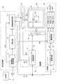
- FIG. 1 is a block diagram illustrating a configuration of a field sequential type liquid crystal display device according to a first embodiment of the present invention.
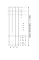
- FIG. It is a figure which shows the relationship between the vertical blanking period with which transparent area information was added, and the video display area in 1 frame period of 1st Embodiment.
- a 1st embodiment it is a figure which compares the case where transparent area information is expressed with the specific gradation value of each color component, and the case where it adds to a vertical blanking period.
- the field sequential type liquid crystal display device it is a diagram showing gradation values of each color component that can be used for video display by adding transparent area information during the vertical blanking period.
- FIG. 16 is a diagram illustrating an example in which one frame period is divided into five subframe periods in the modified examples of the first to fifth embodiments. It is a figure which shows handling a specific gradation value as a transparent gradation in the conventional liquid crystal display device of a field sequential system.
- FIG. 1 is a block diagram showing a configuration of a field sequential type liquid crystal display device according to a first embodiment of the present invention.
- the liquid crystal display device according to this embodiment is a display device that performs color display by a field sequential method in which one frame period is time-divided into three subframe periods.
- the liquid crystal display device includes a signal source 10, a signal processing unit 20, a driving unit 30, a liquid crystal panel 40, and a light source unit 50.
- the signal processing unit 20 includes a transparent gradation control circuit 21, a separation circuit 23, and a frequency conversion circuit 24.
- the drive unit 30 includes an LCD timing control circuit 31, a source driver 32, and a gate driver 33.
- the light source unit 50 includes an LED timing control circuit 51, a backlight driving circuit 52, and red, green, and blue LEDs (Light Emitting Diodes) 53r, 53g, and 53b that emit red, green, and blue light, respectively. Yes. When these LEDs 53r, 53g, and 53b are not distinguished, they may be referred to as “LEDs 53”.
- one frame period is 1/60 seconds, and subframe periods for displaying red, green, and blue images are each 1/180 seconds.
- the color depth of the red component (R component), green component (G component), and blue component (B component) included in the video signal DAT input from the signal source 10 to the signal processing unit 20 is 10 bits.
- the liquid crystal display device can express each color of red, green, and blue with 1024 gradations, approximately 1.70 billion colors (more precisely, 1024 ⁇ 1024 ⁇ 1024 colors) are displayed on the liquid crystal panel 40. can do.
- the color depth of each color component is not limited to 10 bits, and may be, for example, 8 bits, 12 bits, or 14 bits.
- the R component, G component, and B component may be collectively referred to as “each color component”.
- the signal source 10 transmits a video signal DAT representing a video displayed on the display unit 41 of the liquid crystal panel 40 and a control signal TS such as a vertical synchronization signal and a horizontal synchronization signal to the signal processing unit 20 every frame period.
- a control signal TS such as a vertical synchronization signal and a horizontal synchronization signal
- transparent area information Ita indicating whether or not to perform transparent display is added to each pixel forming unit 42 during the vertical blanking period of the video signal DAT.
- the transparent gradation control circuit 21 Upon receiving the video signal DAT from the signal source 10, the transparent gradation control circuit 21 reads the transparent area information Ita added to the video signal DAT and supplies it to the frequency conversion circuit 24.
- the transparent area information Ita is the same information as the LCD information Icd indicating whether or not the pixel forming portion 42 is transparent in each embodiment described later.
- the video signal DAT is input to the separation circuit 23.
- the separation circuit 23 separates the R component, the G component, and the B component from the video signal DAT, time-divides each color component, and sequentially outputs them to the frequency conversion circuit 24.
- the frequency conversion circuit 24 converts the frequency of each color component of the given video signal DAT from 1/60 seconds to 1/180 seconds. Further, the frequency conversion circuit 24 outputs the control signal TS and the transparent area information Ita included in the video signal DAT to the LCD timing control circuit 31.
- the LCD timing control circuit 31 is a control signal such as a source start pulse, a clock signal, and a latch strobe signal necessary for driving the source driver 32 based on the control signal TS and the transparent area information Ita given from the frequency conversion circuit 24.
- An SCT is generated and output to the source driver 32, and a control signal GCT such as a gate start pulse and a clock signal necessary for driving the gate driver 33 is generated and output to the gate driver 33.
- the LCD timing control circuit 31 uses the control signals SCT and GCT for driving the source driver 32 and the gate driver 33 as frequencies in order to synchronize the operation of the frequency conversion circuit 24 with the operations of the source driver 32 and the gate driver 33.
- the conversion circuit 24 is also provided. Based on the control signals SCT and GCT given from the LCD timing control circuit 31, the frequency conversion circuit 24 converts each color component of the video signal DAT given from the separation circuit 23 and the transparent area given from the transparent gradation control circuit 21. Information Ita is given to the source driver 32.
- a plurality of source lines SL, a plurality of gate lines GL, and a plurality of pixel formations corresponding to the intersections of the source lines SL and the gate lines GL are formed.
- a portion 42 is formed.
- a panel capable of high-speed response is used for the liquid crystal panel 40 so that an image of each color component can be displayed every 1/180 second.
- the display unit 41 only one pixel formation unit 42 connected to the source line SL and the gate line GL is shown for convenience.
- the source driver 32 drives signals for each color component from the R component, G component, and B component included in the video signal DAT supplied from the frequency conversion circuit 24. Voltages are generated in order, the drive signal voltages are time-divisionally applied to the source line SL in order, and the pixel forming unit 42 to be transparently displayed based on the transparent area information Ita has a transparent level corresponding to the transparent gradation. The application of the regulated voltage Vt is repeated every subframe period.
- the gate driver 33 Based on the control signal GCT supplied from the LCD timing control circuit 31, the gate driver 33 sequentially applies to the plurality of gate lines GL every subframe period to activate the gate lines GL one by one. Is repeated every subframe period.
- the frequency conversion circuit 24 controls the control signal TS and the transparent area information in order to control the turning on and off of the LED 53 that functions as a backlight in accordance with the timing at which the driving signal voltage of each color component is applied to the pixel forming unit 42. Ita is also given to the LED timing control circuit 51.
- the LED timing control circuit 51 generates a backlight control signal BCT for controlling lighting and extinguishing of the LED 53 based on the control signal TS and the transparent area information Ita, and provides the backlight driving circuit 52 with the backlight control signal BCT.
- a red LED (Light Emitting Diode) 53r, a green LED 53g, and a blue LED 53b that irradiate the liquid crystal panel 40 with red, green, and blue light, respectively, are disposed on the back side of the liquid crystal panel 40.
- the backlight control signal BCT provided from the LED timing control circuit 51 includes lighting times, extinguishing times, driving current values, and the like of the LEDs 53r, 53g, and 53b of the respective colors. At this time, if the drive current passed through the LED 53 arranged at the position corresponding to the pixel forming portion 42 is increased, the luminance of the LED increases, and the pixel forming portion 42 at the position corresponding to the LED is transparently displayed.
- the backlight drive circuit 52 turns on and off the LED 53 with a predetermined luminance based on the backlight control signal BCT provided from the LED timing control circuit 51, and also forms a pixel display section 42 to be transparently displayed.
- a large drive current is passed through the LED 53 at a position corresponding to.
- the drive current for the LED 53 is supplied from a power supply circuit (not shown).
- the driving signal voltage and the transparent gradation voltage Vt are applied to the source line SL, the scanning signal is applied to the gate line GL, and light of each color is irradiated from the LED 53 to the liquid crystal panel 40 in order.
- the driving signal voltage is applied to each pixel forming unit 42 of the display unit 41, and the video represented by the video signal DAT is displayed on the display unit 41.
- the pixel forming unit 42 to which the transparent gradation voltage Vt generated based on the transparent area information Ita is applied becomes transparent, and the background can be seen through the pixel forming unit 42.
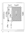
- FIG. 2 is a diagram illustrating a relationship between the vertical blanking period to which the transparent area information is added and the video display area in one frame period of the present embodiment.
- the horizontal synchronizing signal HS shown in FIG. 2 defines one horizontal scanning period
- the vertical synchronizing signal VS defines one vertical scanning period.
- an active area and a blanking area surrounding it are set.
- the blanking area includes a vertical blanking area and a horizontal blanking area.
- the upper and lower areas of the video display area are vertical blanking areas
- the left and right areas are horizontal blanking areas.
- the vertical synchronization signal VS and the horizontal synchronization signal HS are described as signal waveforms in the case of positive logic, but these signals may be signal waveforms in the case of negative logic.
- the active area includes a video display area composed of 1920 pixels in the horizontal direction and 1080 pixels in the vertical direction, and a back porch period in the vertical blanking period to which transparent area information is added (hereinafter, unless otherwise specified in the description of this embodiment).
- This area includes “vertical blanking period”.
- Each pixel forming unit 42 is composed of red, green, and blue sub-pixels (not shown). If the color depth of each color component in each sub-pixel is 10 bits, the number of bits A1 included in one horizontal scanning period of the video display area can be obtained by the following equation (1).
- A1 1920 ⁇ 3 ⁇ 10 (1)
- the transparent area information is 1-bit information indicating whether or not each pixel is transparent.
- the pixel forming unit 42 is not transparent when the transparent area information is “0”, and is transparent when the transparent area information is “1”. Therefore, the number of bits A2 of the transparent area information necessary to indicate whether or not all the pixels in the video display area are transparent is obtained by the following equation (2).
- A2 1920 ⁇ 1080 ⁇ 1 (2)
- the vertical data corresponding to 36 lines from the first data enable (Data Enable) in the vertical blanking period is used.
- a blanking period is required. Since this transparent area information is given as a part of the active area in the vertical blanking period, the active area included in the video signal DAT transmitted from the signal source 10 is (1080 + 36) lines.
- the vertical blanking period to which the transparent area information is added is adjacent to the video display area. Note that the vertical blanking period is set to include at least 36 lines or more so that the transparent area information of all the pixel forming portions 42 can be added.
- the transparent area information added in the vertical blanking period is adjacent to the video display area, but for example, information on the transparent area after 5 clocks from the falling edge of the vertical synchronization signal VS. Therefore, the transparent area information added during the vertical blanking period may not be adjacent to the video display area.
- the transparent area information is added to the back porch period of the vertical blanking period, but may be added to the front porch period of the vertical blanking period. In this case, the transparent area information added to the front porch period is not information in the current frame period but information in the next frame period.
- FIG. 3 is a diagram comparing the case where the transparent area information is represented by a specific gradation value of each color component and the case where it is added to the vertical blanking period.
- a video is displayed in an area of 1920 ⁇ 1080 pixels, which is a video display area, with an R component, a G component, and a B component having a color depth of 10 bits.
- the case of the present embodiment will be described as compared to the conventional case.
- each color component in the transparent display area, the 1023 gradation value of each color component is assigned to the transparent gradation. For this reason, when displaying an image in the image display area, each color component can be expressed only by 1023 gradations of 0 to 1022 gradation values, and pixel values (1023, 1023, 1023) are assigned to transparent gradations. The color represented by the pixel value cannot be displayed.
- each color component can be expressed by 1024 gradations of 0 to 1023 gradation values, and even when a transparent display area is provided, an image can be displayed in a full range of colors.
- FIG. 4 is a diagram showing gradation values of each color component that can be used when displaying an image by adding transparent area information during a vertical blanking period in a field sequential type liquid crystal display device.
- each color has 1024 gradations from 0 gradation value to 1023 gradation value. It is possible to display.
- pixel values (1023, 1023, 1023) are different from the case shown in FIG. 14 by adding transparent area information during the vertical blanking period. Need not be assigned to the transparent gradation, and the color represented by the pixel value can also be used when displaying an image. As a result, the liquid crystal display device can display images in all colors even when performing transparent display.
- the liquid crystal display device in the field sequential type liquid crystal display device, by adding transparent area information during the vertical blanking period, a part of the color depth of each of the R component, G component, and B component is assigned to the transparent gradation. There is no need. Accordingly, the liquid crystal display device can display an image using all colors even when performing transparent display.
- FIG. 5 is a block diagram showing a configuration of a liquid crystal display device according to the second embodiment of the present invention. Since the liquid crystal display device according to the present embodiment is composed of the same circuit as the circuit constituting the liquid crystal display device shown in FIG. 1, the same reference numerals as those of the liquid crystal display device are given to the respective circuits of the liquid crystal display device. It is attached. However, in these liquid crystal display devices, since the connection destination of the transparent gradation control circuit 21 is partially different, this point will be described.
- the transparent gradation control circuit 21 is only connected to the separation circuit 23 and the frequency conversion circuit 24. In addition, it is also connected to the backlight drive circuit 52. This is due to the following reason.
- the transparent area information is represented by 1-bit information indicating whether or not each pixel is transparent.
- the transparent area information is only information indicating whether or not each pixel forming unit 42 is transparent (hereinafter referred to as “LCD information Icd” in the present embodiment).
- the transparent gradation control circuit 21 is also connected to the backlight drive circuit 52 in order to give the LED information Ied included in the transparent area information added in the vertical blanking period to the backlight drive circuit 52.
- the LCD information Icd may be referred to as “transparent display information”, and the LED information Ied may be referred to as “transparency information”.
- the liquid crystal display device is a see-through type display device in which the background of the liquid crystal panel 40 can be seen through
- the number of LEDs 53 arranged on the back side of the liquid crystal panel 40 is made smaller than usual.
- the transparency of the pixel forming unit 42 is set by adjusting the luminance of the LED 53, so that the pixel forming unit 42 has a one-to-one correspondence with the pixel forming unit 42 in order to set the transparency. It is preferable to arrange the LED 53 in the above. However, if the number of LEDs 53 is increased, light from the background is less likely to be transmitted through the liquid crystal panel 40 during transparent display, so that the background is less visible through the liquid crystal panel 40. Therefore, it is preferable to increase the number of LEDs 53 within a range where the background of the liquid crystal panel 40 is sufficiently visible.
- the transparent area information used in the present embodiment represents the transparent state of one pixel with 2-bit information. Of these bits, 1 bit is LCD information Icd indicating whether or not the pixel forming portion 42 is transparent. Similarly to the case of the first embodiment, “0” is set when the pixel forming portion 42 is not transparent. ", And" 1 "if it is transparent.
- the other 1 bit is LED information Ied indicating the transparency of the pixel forming unit 42 when the pixel forming unit 42 is transparent.
- the transparency of the pixel forming portion 42 is determined by the luminance of the LED 53 of each color. If the luminance of the LED 53 is increased, the transparency of the pixel forming portion 42 is increased, and if the luminance of the LED 53 is decreased, the transparency of the pixel forming portion 42 is decreased. Therefore, by setting the LED information Ied indicating the luminance of the LED 53 to “0” or “1”, it is possible to set the pixel forming portion 42 to be transparently displayed to one of two levels of transparency. Specifically, the drive current of the LED 53 is increased or decreased by controlling the backlight drive circuit 52.
- the liquid crystal display device can set the transparency of the pixel forming unit 42 that should perform transparent display, based on the LED information Ied included in the transparent area information.
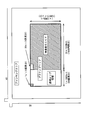
- FIG. 6 is a diagram illustrating the relationship between the vertical blanking period to which the transparent area information is added and the video display area in one frame period of the present embodiment.
- the active area includes a video display area composed of 1920 pixels in the horizontal direction and 1080 pixels in the vertical direction, and a back porch period (hereinafter referred to as the present embodiment) of the vertical blanking period to which transparent area information is added.
- the present embodiment a back porch period
- Each pixel forming unit 42 includes three sub-pixels (not shown) of red, green, and blue. If the color depth of each color component in each sub-pixel is 10 bits, the number of bits B1 included in one horizontal scanning period of the video display area can be obtained by the following equation (4).
- B1 1920 ⁇ 3 ⁇ 10 (4)
- the transparent area information added during the vertical blanking period is different from the number of bits in the video display area, and is 1-bit LCD information Icd indicating whether or not each pixel forming unit 42 is transparent, and see-through.
- the information is made up of a total of 2 bits of 1-bit LED information Ied representing the transparency of the pixel forming section 42 set as described above, and these are given continuously. Therefore, the total number of bits B2 of the transparent area information in one frame period is obtained by the following equation (5).
- B2 1920 ⁇ 1080 ⁇ 2 (5)
- the LED information is described as 1-bit information, but may be multi-bit information.
- the transparency of the pixel forming portion to be transparently displayed can be set to more stages instead of being set to one of the two stages.
- the transparent area information is described as being added to the back porch period of the vertical blanking period, but can be added to the front porch period.
- the transparent area information added to the front porch period is not information in the current frame period but information in the next frame period.
- the liquid crystal display device in the field sequential type liquid crystal display device, by adding the transparent area information during the vertical blanking period, the R component, the G component, and the B component. It is not necessary to assign a part of each color depth to the transparent area information. Accordingly, the liquid crystal display device can display an image using all colors even when performing transparent display.
- the liquid crystal display device can set the transparency of the pixel forming portion 42 to be transparently displayed by adjusting the luminance of the LED 53 based on the LED information Ied.
- the liquid crystal display device according to the third embodiment of the present invention adds 1-bit transparent area information to the horizontal blanking period.
- the configuration of the liquid crystal display device according to the present embodiment is the same as the configuration of the liquid crystal display device shown in FIG. 1, the block diagram and description of the liquid crystal display device according to the present embodiment are omitted.
- FIG. 7 is a diagram illustrating the relationship between the horizontal blanking period to which the transparent area information is added and the video display area in one frame period of the present embodiment.
- the active area is composed of a video display area composed of 1920 pixels in the horizontal direction and 1080 pixels in the vertical direction, and the horizontal blanking period to which the transparent area information is added is the active area. Is not included.
- Each pixel forming unit 42 includes three sub pixel forming units (not shown) of red, green, and blue. If the color depth of these sub-pixels is 10 bits, the number of bits of one pixel forming unit 42 is (3 ⁇ 10) bits.
- the transparent area information is only the LCD information Icd indicating whether or not each pixel forming unit 42 is transparent, one pixel forming unit 42 has one bit. Therefore, the number of pixels Lh of the transparent area information corresponding to 1920 pixels included in one horizontal scanning period (one line) of the video display area is obtained by the following equation (7).
- the transparent area information for 64 pixels may be added for one line in the horizontal blanking period. Therefore, in the present embodiment, transparent area information is added to 64 pixels from the falling edge of the vertical synchronization signal VS for each line in the horizontal blanking period.
- the transparent area information for 64 pixels is added for each line from the first data enable in the horizontal blanking period. Is repeated for 1080 lines. Since this transparent area information is added in the horizontal blanking period separately from the active area, the video signal DAT corresponding to 1920 pixels of the active area for each line from the signal source 10 and 64 pixels separately from the active area. Transparent area information is transmitted. For this reason, as shown in FIG. 7, the horizontal blanking period to which the transparent area information is added is not adjacent to the video display area. In this case, the horizontal blanking period is set to include at least 64 pixels per line so that the transparent area information of all the pixel forming portions 42 can be added.
- the transparent area information is described as being added to the back porch period of the horizontal blanking period. However, it may be added to the front porch period. In this case, the transparent area information added to the front porch period is not information in the current frame period, but information in the next frame period.
- the liquid crystal display device by adding transparent area information in the horizontal blanking period, similarly to the case of adding transparent area information in the vertical blanking period, the R component, G A part of the color depths of the component and the B component may not be used as the transparent gradation. Accordingly, the liquid crystal display device can display an image using all colors even when performing transparent display.
- FIG. 8 is a diagram showing another relationship between the video display area and the horizontal blanking period in which transparent area information is added in one frame period.
- 64 pixels from the time when the vertical synchronization signal VS falls are used as the transparent area information.
- the horizontal blanking period with the transparent area information added is set at a position away from the video display area. Therefore, as shown in FIG. 8, by increasing the data enable transmitted from the signal source 10, an active area including a video display area and a horizontal blanking period to which transparent area information is added is formed.
- This active area includes 1984 pixels in total, including 1920 pixels of the video display area and 64 pixels from the rise time of the data enable, and further includes 1080 such lines. Yes. Therefore, unlike the case shown in FIG. 7, the video display area and the transparent area information added in the horizontal blanking period are adjacent to each other. Since the effect in this case is the same as the effect of the liquid crystal display device shown in FIG.
- the transparent area information is 1-bit information. However, as long as it is within the range of the number of bits that can be added during the horizontal blanking period, information of 2 bits or more may be added as the transparent area information, as in the second embodiment.
- the transparent area information is represented by 2 bits as in the liquid crystal display device according to the second embodiment. However, unlike the case of the first embodiment, 1 bit of 2-bit transparent area information is added to the vertical blanking period, and the other 1 bit is added to the horizontal blanking period.
- the configuration of the liquid crystal display device according to the present embodiment is the same as the configuration of the liquid crystal display device shown in FIG.
- the transparent area information transmitted from the signal source 10 includes 2-bit information.
- the 1-bit information of the transparent area information is LCD information Icd that is “0” when each pixel forming unit 42 is not transparent and “1” when each pixel forming unit 42 is transparent. This information is information given to the source driver 32 via the frequency conversion circuit 24.
- the other 1-bit information is LED information Ied indicating the transparency of the pixel forming unit 42 to be transparently displayed. Specifically, when the LED information Ied is “0”, the drive current value of each LED 53 is decreased to lower the luminance of the LED 53, and the transparency of the pixel forming portion 42 is set to be lower.
- the LED information Ied is “1”
- the drive current value of each LED 53 is increased to increase the luminance of the LED 53, and the transparency of the pixel forming portion 42 is set to be high.
- the LED information Ied can set the transparency of the pixel forming portion 42 to be transparently displayed by controlling the luminance of the LED 53.
- FIG. 9 is a diagram showing the relationship between the vertical and horizontal blanking periods to which the transparent area information is added and the video display area in one frame period of the present embodiment.
- each color depth of the R component, the G component, and the B component is 10 bits, and the LCD information and the LED information are each 1 bit, the LED information is added to the vertical blanking period.
- the information for LCD is added to the horizontal blanking period and transmitted.
- the number of pixels in the video display area is 1920 ⁇ 1080 pixels.
- 64 pixels are required for each horizontal period as determined in the third embodiment. Therefore, the horizontal width of the active area is 1984 pixels when combined with the 1920 pixels of the video display area.
- the number of lines Lv3 required when adding the LED information to the vertical blanking period is obtained by the following formula (10).
- the number of lines in the vertical direction of the active area is (35 + 1080) lines.
- LED information for 35 lines is transmitted from the first data enable in the vertical blanking period.
- the LCD information for 64 pixels (one line) is transmitted from the first data enable in the horizontal blanking period.
- a video signal DAT for 1920 pixels (one line) is transmitted.
- the transmission of the LCD information and the video signal DAT for one line is completed, the transmission of the LCD information and the video signal DAT for the next one line is performed. In this way, the LCD information and the video signal DAT are transmitted for one line, for a total of 1080 lines. In this way, the video signal and the transparent area information included in the active area are transmitted.
- each color of the R component, the G component, and the B component is obtained by adding LCD information during the horizontal blanking period. It becomes unnecessary to use a part of the depth as a transparent gradation. Accordingly, the liquid crystal display device can display an image using all colors even when performing transparent display. Further, by adding the LED information during the vertical blanking period, the liquid crystal display device can set the transparency by adjusting the luminance of the LEDs 53 of each color included in the backlight unit based on the information.
- the transparency information is not set to one of the two levels, as in the case of the second embodiment. It can also be set in stages.
- the LED information is added to the vertical blanking period and the LCD information is added to the horizontal blanking period.
- the LED information may be added to the horizontal blanking period, and the LCD information may be added to the vertical blanking period. In this case, the same effect as described above can be obtained.
- the liquid crystal display device according to the fifth embodiment of the present invention does not add transparent area information to the vertical or horizontal blanking period, It is added to the signal DAT. That is, a new number of bits is added in addition to the number of bits representing the color depth of the R component, G component, and B component included in the video signal DAT, and the added number of bits is assigned to the transparent area information.
- the configuration of the liquid crystal display device according to the present embodiment is the same as the configuration of the liquid crystal display device shown in FIG.
- each color component of the video signal DAT is assigned to the color depth of each color component as a 10-bit signal, and each color component is further expanded by adding 2 bits. 2 bits are assigned to the transparent area information. For this reason, each color component of the video signal is apparently 12 bits.
- FIG. 10 is a diagram showing how to use the number of bits representing the color depth of the R component, the G component, and the B component included in the video signal DAT. More specifically, FIG. 10A is a diagram showing the number of bits of the R component, G component, and B component, and FIG. 10B is the number of bits representing the color depths of the R component, G component, and B component. It is a figure which shows the bit number allocated to transparent area information. As shown in FIG. 10, the number of bits of the R component, G component, and B component are all expanded to 12 bits. However, among them, 10 bits are assigned to each color component for the color depth of the video, and the remaining 2 bits are assigned to the transparent area information.
- the transparent gradation control circuit 21 of the liquid crystal display device If the 2-bit transparent area information added to the video signal DAT is read by the transparent gradation control circuit 21 of the liquid crystal display device, 1-bit information of the 2-bit information included in the transparent area information is used as LCD information. The signal is supplied to the frequency conversion circuit 24, and the other 1 bit is supplied to the backlight drive circuit 52 as LED information. Since the subsequent operation of the liquid crystal display device is the same as that described in the fourth embodiment, the description thereof is omitted.
- the color depth of each color component can be represented by 10 bits.
- the pixel values (1023, 1023, 1023) can be assigned to the transparent gradation, and the color represented by the pixel value can also be used when displaying an image.
- the liquid crystal display device can display images using all colors even when performing transparent display.
- 2 bits are added to 10 bits representing each color component of the video signal in order to add the LCD information and the LED information included in the transparent area information.
- only LCD information may be added to one of the two added bits, and LED information may be added to the horizontal blanking period or vertical blanking period, or only LED information is added.
- the information for LCD may be added to the horizontal blanking period or the vertical blanking period in addition to one of the two bits.
- a bit added to 10 bits representing each color component of the video signal may be referred to as an “additional transparent area”.
- the liquid crystal display device is not a field sequential type liquid crystal display device described in each of the first to fifth embodiments but a color filter type liquid crystal display device, and is not a see-through type. / A display device that displays only a color image every 60 seconds.
- FIG. 11 is a block diagram showing a configuration of the liquid crystal display device according to the present embodiment.
- the configuration of the liquid crystal display device is substantially the same as the configuration of the liquid crystal display device shown in FIG.
- hidden area information is added to the vertical blanking period instead of the transparent area information.
- the fill information Inp included in the hidden area information is “0”
- an image is displayed on the pixel formation unit 47 of the display unit 46 of the liquid crystal panel 45.
- the fill information Inp is “1”
- the pixel formation is performed.
- the portion 47 is filled so that no video is displayed. Therefore, in the liquid crystal display device, a hidden area control circuit 22 is provided instead of the transparent gradation control circuit 21.
- the hidden area control circuit 22 reads the paint information Inp added during the vertical blanking period and supplies it to the source driver 32, the LCD timing control circuit 31, and the LED timing control circuit 51.
- the source driver 32 drives signals for each color component from the R component, G component, and B component included in the video signal DAT supplied from the frequency conversion circuit 24. Voltages are generated in order, and the driving signal voltages are time-divisionally applied to the source line SL in order. Further, applying the fill gradation voltage Vn corresponding to the fill gradation to the pixel forming portion 47 to be filled based on the fill information Inp is repeated every subframe period.
- the separation circuit 23 and the frequency conversion circuit 24 may not be included or may be included. However, when the separation circuit 23 and the frequency conversion circuit 24 are included as shown in FIG. 11, it is necessary to stop their operations. Therefore, in FIG. 11, the separation circuit 23 and the frequency conversion circuit 24 are surrounded by a dotted line to indicate that the operation is stopped.
- the liquid crystal panel 40 included in the liquid crystal display device shown in FIG. 1 is replaced with a liquid crystal panel 45 on which a color filter is formed. Even when the information added in the vertical blanking period is hidden area information, the apparatus can display an image by the color filter method or can fill the hidden pixel forming unit 42 so that the image cannot be displayed.
- the liquid crystal display device usable in this embodiment can be manufactured by simply replacing the field sequential type liquid crystal panel 40 with the color filter type liquid crystal panel 45. it can. Thereby, the manufacturing cost of the liquid crystal display device which can be used in this embodiment can be suppressed at low cost.
- FIG. 12 is a diagram showing the relationship between the video display area and the vertical blanking period to which the hidden area information is added in one frame period of the present embodiment.
- This embodiment corresponds to the case where hidden area information is added to the vertical blanking period instead of transparent area information in the case of the first embodiment. Therefore, as shown in FIG. 12, as the number of lines necessary for adding 1-bit hidden area information corresponding to each of 1920 ⁇ 1080 pixels in the video display area during the vertical blanking period of the video display area, 36 lines are required as determined in the first embodiment. Therefore, the (36 + 1080) lines obtained by combining 1080 lines in the video display area and 36 lines to which hidden area information is added are active areas transmitted from the signal source 10.
- the hidden area information may be added to the horizontal blanking period instead of being added to the vertical blanking period.
- the hidden area information may be represented by a plurality of bits, and a part of the hidden area information may be used as character information for displaying a character or the like on a filled pixel, for example.
- the LCD information and the character information included in the hidden area information may be added together in either the vertical blanking period or the horizontal blanking period, or for example, the LCD information may be added to the vertical blanking period and the horizontal blanking period.
- the blanking period may be given to one of the blanking periods, and the character information may be added to the other blanking period.
- the hidden area information is added to the vertical blanking period, so that it is not necessary to assign a part of each color depth of the R component, the G component, and the B component to the hidden area information.
- the liquid crystal display device can express the video in all colors even when providing a hidden area where the video is not displayed.
- the display unit 46 of the liquid crystal panel 45 can be provided with a pixel forming unit 47 filled with a predetermined color, or black characters can be displayed on the pixel forming unit 42 painted with white or the like, for example.
- the transparent area information and the hidden area information may be collectively referred to as “display area information”, and the state when the pixel forming unit 42 is in the transparent state and the filled state are collectively referred to as the “display state”. There is a case.
- the liquid crystal display device divides one frame period into three subframe periods by time division by a field sequential method, and red, green, and blue images are time-divided in each subframe period. Then, color images were displayed by displaying them sequentially.
- FIG. 13 is a diagram illustrating an example when one frame period is divided into five subframe periods.
- a white subframe (W subframe) period for displaying a white image is added before and after a subframe period for displaying red, green, and blue images, and one frame period is divided into five frames. You may comprise by a sub-frame period.
- Such driving can also be realized in the liquid crystal display device shown in FIG.
- the separation circuit 23 separates the R component, the G component, and the B component included in the video signal for each frame period, and before and after reading them by the frequency conversion circuit 24, the W subframe period is set. In the W subframe period, each color component is read out simultaneously. In this case, since 5 subframe periods are provided in 1/60 second which is one frame period, the frequency conversion circuit 24 needs to convert each subframe period to 1/300 seconds.
- the present invention is applicable to a display device such as a liquid crystal display device that performs color display by a field sequential method or a color filter method.
Landscapes
- Engineering & Computer Science (AREA)
- Physics & Mathematics (AREA)
- Computer Hardware Design (AREA)
- General Physics & Mathematics (AREA)
- Theoretical Computer Science (AREA)
- Multimedia (AREA)
- Signal Processing (AREA)
- Chemical & Material Sciences (AREA)
- Crystallography & Structural Chemistry (AREA)
- Computer Graphics (AREA)
- Control Of Indicators Other Than Cathode Ray Tubes (AREA)
Abstract
Traditionnellement, dans une zone d'affichage transparente, une valeur de niveau de gris 1023 de chaque composante de couleur est affectée à un niveau de gris transparent. Par conséquent, lorsqu'une image est affichée dans une zone d'affichage d'image, chaque composante de couleur peut être représentée uniquement par des niveaux de gris 1023 d'une valeur de niveau de gris allant de 0 à 1022, une valeur de pixel (1023, 1023, 1023) n'a pas besoin d'être affectée au niveau de gris transparent, et une couleur représentée par cette valeur de pixel ne peut pas être affichée. Si des informations de zone transparente sont ajoutées à une période d'extinction verticale d'un signal d'image, la valeur de pixel (1023, 1023, 1023) peut être utilisée pour afficher l'image. En conséquence, il devient possible de représenter chaque composante de couleur par des niveaux de gris 1024 d'une valeur de niveau de gris allant de 0 à 1023, et même si la zone d'affichage transparente est prévue, il devient possible d'afficher l'image dans une gamme complète de couleurs.
Priority Applications (2)
| Application Number | Priority Date | Filing Date | Title |
|---|---|---|---|
| CN201580031448.2A CN106463093B (zh) | 2014-07-04 | 2015-06-04 | 液晶显示装置 |
| US15/318,456 US10033957B2 (en) | 2014-04-07 | 2015-06-04 | Liquid crystal display device |
Applications Claiming Priority (2)
| Application Number | Priority Date | Filing Date | Title |
|---|---|---|---|
| JP2014139022 | 2014-07-04 | ||
| JP2014-139022 | 2014-07-04 |
Publications (1)
| Publication Number | Publication Date |
|---|---|
| WO2016002424A1 true WO2016002424A1 (fr) | 2016-01-07 |
Family
ID=55018976
Family Applications (1)
| Application Number | Title | Priority Date | Filing Date |
|---|---|---|---|
| PCT/JP2015/066144 Ceased WO2016002424A1 (fr) | 2014-04-07 | 2015-06-04 | Dispositif d'affichage à cristaux liquides |
Country Status (3)
| Country | Link |
|---|---|
| US (1) | US10033957B2 (fr) |
| CN (1) | CN106463093B (fr) |
| WO (1) | WO2016002424A1 (fr) |
Families Citing this family (10)
| Publication number | Priority date | Publication date | Assignee | Title |
|---|---|---|---|---|
| US9922588B2 (en) * | 2014-01-29 | 2018-03-20 | Sharp Kabushiki Kaisha | Image display device |
| CN104505055B (zh) * | 2014-12-31 | 2017-02-22 | 深圳创维-Rgb电子有限公司 | 调整背光亮度的方法及装置 |
| CN105898613A (zh) * | 2015-08-21 | 2016-08-24 | 乐视致新电子科技(天津)有限公司 | 一种设置屏幕菜单透明度的方法和装置 |
| US10388212B2 (en) | 2017-06-12 | 2019-08-20 | Motorola Mobility Llc | Organic light emitting diode display with transparent pixel portion and corresponding devices |
| JP2019090858A (ja) * | 2017-11-10 | 2019-06-13 | キヤノン株式会社 | 表示装置、表示制御装置及び表示制御方法 |
| CN109545155B (zh) * | 2019-02-25 | 2019-05-07 | 南京熊猫电子制造有限公司 | 一种改善场序显示色彩均匀度的装置和方法 |
| CN110660369B (zh) * | 2019-09-06 | 2022-05-20 | 北京集创北方科技股份有限公司 | 显示驱动方法、源极驱动电路、驱动芯片以及显示装置 |
| KR102870521B1 (ko) * | 2020-08-04 | 2025-10-16 | 삼성디스플레이 주식회사 | 표시장치 |
| JP2023056854A (ja) * | 2021-10-08 | 2023-04-20 | 株式会社Joled | 制御装置、表示装置及び制御方法 |
| CN116811260A (zh) * | 2023-08-31 | 2023-09-29 | 禹创半导体(深圳)有限公司 | 数据传输方法、装置、设备及存储介质 |
Citations (4)
| Publication number | Priority date | Publication date | Assignee | Title |
|---|---|---|---|---|
| JPH08317350A (ja) * | 1995-05-19 | 1996-11-29 | Hitachi Ltd | 字幕表示装置 |
| JPH08331527A (ja) * | 1995-05-31 | 1996-12-13 | Toshiba Corp | 文字情報信号受信装置 |
| WO2007102413A1 (fr) * | 2006-03-03 | 2007-09-13 | Matsushita Electric Industrial Co., Ltd. | Dispositif émetteur, dispositif récepteur et dispositif émetteur/récepteur |
| WO2014097976A1 (fr) * | 2012-12-21 | 2014-06-26 | シャープ株式会社 | Dispositif d'affichage à cristaux liquides |
Family Cites Families (9)
| Publication number | Priority date | Publication date | Assignee | Title |
|---|---|---|---|---|
| TW514854B (en) * | 2000-08-23 | 2002-12-21 | Semiconductor Energy Lab | Portable information apparatus and method of driving the same |
| JP4063158B2 (ja) | 2003-07-10 | 2008-03-19 | ソニー株式会社 | 画像合成装置及び方法、並びに画像再生装置 |
| JP4627148B2 (ja) * | 2004-04-09 | 2011-02-09 | 株式会社 日立ディスプレイズ | 表示装置 |
| US7898623B2 (en) * | 2005-07-04 | 2011-03-01 | Semiconductor Energy Laboratory Co., Ltd. | Display device, electronic device and method of driving display device |
| CN101432793B (zh) * | 2006-07-14 | 2012-02-01 | 夏普株式会社 | 有源矩阵基片和配备该基片的显示装置 |
| EP2124437A4 (fr) | 2007-03-13 | 2010-12-29 | Sony Corp | Système de communication, émetteur, procédé de transmission, récepteur et procédé de réception |
| WO2011122271A1 (fr) * | 2010-03-31 | 2011-10-06 | Semiconductor Energy Laboratory Co., Ltd. | Dispositif d'affichage à séquence de trames |
| US8907881B2 (en) * | 2010-04-09 | 2014-12-09 | Semiconductor Energy Laboratory Co., Ltd. | Liquid crystal display device and method for driving the same |
| CN102971784B (zh) * | 2010-07-02 | 2016-08-03 | 株式会社半导体能源研究所 | 液晶显示装置及驱动液晶显示装置的方法 |
-
2015
- 2015-06-04 WO PCT/JP2015/066144 patent/WO2016002424A1/fr not_active Ceased
- 2015-06-04 US US15/318,456 patent/US10033957B2/en active Active
- 2015-06-04 CN CN201580031448.2A patent/CN106463093B/zh not_active Expired - Fee Related
Patent Citations (4)
| Publication number | Priority date | Publication date | Assignee | Title |
|---|---|---|---|---|
| JPH08317350A (ja) * | 1995-05-19 | 1996-11-29 | Hitachi Ltd | 字幕表示装置 |
| JPH08331527A (ja) * | 1995-05-31 | 1996-12-13 | Toshiba Corp | 文字情報信号受信装置 |
| WO2007102413A1 (fr) * | 2006-03-03 | 2007-09-13 | Matsushita Electric Industrial Co., Ltd. | Dispositif émetteur, dispositif récepteur et dispositif émetteur/récepteur |
| WO2014097976A1 (fr) * | 2012-12-21 | 2014-06-26 | シャープ株式会社 | Dispositif d'affichage à cristaux liquides |
Also Published As
| Publication number | Publication date |
|---|---|
| CN106463093B (zh) | 2019-04-02 |
| US20170150085A1 (en) | 2017-05-25 |
| US10033957B2 (en) | 2018-07-24 |
| CN106463093A (zh) | 2017-02-22 |
Similar Documents
| Publication | Publication Date | Title |
|---|---|---|
| WO2016002424A1 (fr) | Dispositif d'affichage à cristaux liquides | |
| CN100589013C (zh) | 液晶显示器件及其驱动方法 | |
| CN104299575B (zh) | 一种时序混色的显示控制方法、装置及显示器 | |
| CN104575416B (zh) | 显示装置及其驱动方法 | |
| CN101414449B (zh) | 彩色序列式显示器的驱动方法 | |
| KR101219143B1 (ko) | 액정 표시 장치와 이의 구동 방법 | |
| EP2615603A2 (fr) | Appareil et procédé d'affichage d'image | |
| JPWO2015114943A1 (ja) | 画像表示装置 | |
| US20170047021A1 (en) | Display device | |
| KR101252089B1 (ko) | 액정 표시 장치 | |
| CN103137090A (zh) | 显示图像的设备和方法 | |
| KR101859481B1 (ko) | 표시장치 및 그 구동방법 | |
| US9916806B2 (en) | Liquid crystal display apparatus and driving method thereof | |
| TWI545540B (zh) | 拼接屏顯示裝置以及其顯示驅動方法 | |
| KR102185676B1 (ko) | 백라이트 디밍 제어 장치 | |
| WO2013150913A1 (fr) | Dispositif d'affichage d'image et procédé d'affichage d'image | |
| KR20130022600A (ko) | 액정표시장치와 그 구동방법 | |
| KR102509878B1 (ko) | 시간분할 구동 방법 및 이를 구현하는 장치 | |
| US20160293130A1 (en) | Display device | |
| KR20100019186A (ko) | 액정 표시장치의 구동장치와 그 구동방법 | |
| US7576722B2 (en) | Gray-scale method for a flat panel display | |
| US20160049122A1 (en) | Display apparatus and method of driving the same | |
| CN104361867B (zh) | 拼接屏显示装置以及其显示驱动方法 | |
| KR102532108B1 (ko) | 표시장치 및 표시장치의 구동 방법 | |
| KR102150290B1 (ko) | 액정표시장치 |
Legal Events
| Date | Code | Title | Description |
|---|---|---|---|
| 121 | Ep: the epo has been informed by wipo that ep was designated in this application |
Ref document number: 15815184 Country of ref document: EP Kind code of ref document: A1 |
|
| WWE | Wipo information: entry into national phase |
Ref document number: 15318456 Country of ref document: US |
|
| NENP | Non-entry into the national phase |
Ref country code: DE |
|
| NENP | Non-entry into the national phase |
Ref country code: JP |
|
| 122 | Ep: pct application non-entry in european phase |
Ref document number: 15815184 Country of ref document: EP Kind code of ref document: A1 |