WO2016006707A1 - Article façonné en courbe - Google Patents
Article façonné en courbe Download PDFInfo
- Publication number
- WO2016006707A1 WO2016006707A1 PCT/JP2015/069995 JP2015069995W WO2016006707A1 WO 2016006707 A1 WO2016006707 A1 WO 2016006707A1 JP 2015069995 W JP2015069995 W JP 2015069995W WO 2016006707 A1 WO2016006707 A1 WO 2016006707A1
- Authority
- WO
- WIPO (PCT)
- Prior art keywords
- peripheral wall
- bending
- core material
- cross
- bent product
- Prior art date
- Legal status (The legal status is an assumption and is not a legal conclusion. Google has not performed a legal analysis and makes no representation as to the accuracy of the status listed.)
- Ceased
Links
Images




Classifications
-
- F—MECHANICAL ENGINEERING; LIGHTING; HEATING; WEAPONS; BLASTING
- F16—ENGINEERING ELEMENTS AND UNITS; GENERAL MEASURES FOR PRODUCING AND MAINTAINING EFFECTIVE FUNCTIONING OF MACHINES OR INSTALLATIONS; THERMAL INSULATION IN GENERAL
- F16L—PIPES; JOINTS OR FITTINGS FOR PIPES; SUPPORTS FOR PIPES, CABLES OR PROTECTIVE TUBING; MEANS FOR THERMAL INSULATION IN GENERAL
- F16L9/00—Rigid pipes
- F16L9/003—Rigid pipes with a rectangular cross-section
-
- B—PERFORMING OPERATIONS; TRANSPORTING
- B21—MECHANICAL METAL-WORKING WITHOUT ESSENTIALLY REMOVING MATERIAL; PUNCHING METAL
- B21C—MANUFACTURE OF METAL SHEETS, WIRE, RODS, TUBES, PROFILES OR LIKE SEMI-MANUFACTURED PRODUCTS OTHERWISE THAN BY ROLLING; AUXILIARY OPERATIONS USED IN CONNECTION WITH METAL-WORKING WITHOUT ESSENTIALLY REMOVING MATERIAL
- B21C23/00—Extruding metal; Impact extrusion
- B21C23/02—Making uncoated products
- B21C23/04—Making uncoated products by direct extrusion
- B21C23/14—Making other products
- B21C23/142—Making profiles
-
- B—PERFORMING OPERATIONS; TRANSPORTING
- B21—MECHANICAL METAL-WORKING WITHOUT ESSENTIALLY REMOVING MATERIAL; PUNCHING METAL
- B21D—WORKING OR PROCESSING OF SHEET METAL OR METAL TUBES, RODS OR PROFILES WITHOUT ESSENTIALLY REMOVING MATERIAL; PUNCHING METAL
- B21D7/00—Bending rods, profiles, or tubes
-
- B—PERFORMING OPERATIONS; TRANSPORTING
- B29—WORKING OF PLASTICS; WORKING OF SUBSTANCES IN A PLASTIC STATE IN GENERAL
- B29C—SHAPING OR JOINING OF PLASTICS; SHAPING OF MATERIAL IN A PLASTIC STATE, NOT OTHERWISE PROVIDED FOR; AFTER-TREATMENT OF THE SHAPED PRODUCTS, e.g. REPAIRING
- B29C48/00—Extrusion moulding, i.e. expressing the moulding material through a die or nozzle which imparts the desired form; Apparatus therefor
- B29C48/15—Extrusion moulding, i.e. expressing the moulding material through a die or nozzle which imparts the desired form; Apparatus therefor incorporating preformed parts or layers, e.g. extrusion moulding around inserts
-
- B—PERFORMING OPERATIONS; TRANSPORTING
- B29—WORKING OF PLASTICS; WORKING OF SUBSTANCES IN A PLASTIC STATE IN GENERAL
- B29C—SHAPING OR JOINING OF PLASTICS; SHAPING OF MATERIAL IN A PLASTIC STATE, NOT OTHERWISE PROVIDED FOR; AFTER-TREATMENT OF THE SHAPED PRODUCTS, e.g. REPAIRING
- B29C53/00—Shaping by bending, folding, twisting, straightening or flattening; Apparatus therefor
- B29C53/02—Bending or folding
- B29C53/08—Bending or folding of tubes or other profiled members
-
- B—PERFORMING OPERATIONS; TRANSPORTING
- B32—LAYERED PRODUCTS
- B32B—LAYERED PRODUCTS, i.e. PRODUCTS BUILT-UP OF STRATA OF FLAT OR NON-FLAT, e.g. CELLULAR OR HONEYCOMB, FORM
- B32B15/00—Layered products comprising a layer of metal
- B32B15/02—Layer formed of wires, e.g. mesh
-
- B—PERFORMING OPERATIONS; TRANSPORTING
- B32—LAYERED PRODUCTS
- B32B—LAYERED PRODUCTS, i.e. PRODUCTS BUILT-UP OF STRATA OF FLAT OR NON-FLAT, e.g. CELLULAR OR HONEYCOMB, FORM
- B32B15/00—Layered products comprising a layer of metal
- B32B15/04—Layered products comprising a layer of metal comprising metal as the main or only constituent of a layer, which is next to another layer of the same or of a different material
- B32B15/08—Layered products comprising a layer of metal comprising metal as the main or only constituent of a layer, which is next to another layer of the same or of a different material of synthetic resin
- B32B15/085—Layered products comprising a layer of metal comprising metal as the main or only constituent of a layer, which is next to another layer of the same or of a different material of synthetic resin comprising polyolefins
-
- F—MECHANICAL ENGINEERING; LIGHTING; HEATING; WEAPONS; BLASTING
- F16—ENGINEERING ELEMENTS AND UNITS; GENERAL MEASURES FOR PRODUCING AND MAINTAINING EFFECTIVE FUNCTIONING OF MACHINES OR INSTALLATIONS; THERMAL INSULATION IN GENERAL
- F16L—PIPES; JOINTS OR FITTINGS FOR PIPES; SUPPORTS FOR PIPES, CABLES OR PROTECTIVE TUBING; MEANS FOR THERMAL INSULATION IN GENERAL
- F16L9/00—Rigid pipes
- F16L9/14—Compound tubes, i.e. made of materials not wholly covered by any one of the preceding groups
- F16L9/147—Compound tubes, i.e. made of materials not wholly covered by any one of the preceding groups comprising only layers of metal and plastics with or without reinforcement
-
- F—MECHANICAL ENGINEERING; LIGHTING; HEATING; WEAPONS; BLASTING
- F16—ENGINEERING ELEMENTS AND UNITS; GENERAL MEASURES FOR PRODUCING AND MAINTAINING EFFECTIVE FUNCTIONING OF MACHINES OR INSTALLATIONS; THERMAL INSULATION IN GENERAL
- F16L—PIPES; JOINTS OR FITTINGS FOR PIPES; SUPPORTS FOR PIPES, CABLES OR PROTECTIVE TUBING; MEANS FOR THERMAL INSULATION IN GENERAL
- F16L9/00—Rigid pipes
- F16L9/18—Double-walled pipes; Multi-channel pipes or pipe assemblies
- F16L9/19—Multi-channel pipes or pipe assemblies
-
- B—PERFORMING OPERATIONS; TRANSPORTING
- B21—MECHANICAL METAL-WORKING WITHOUT ESSENTIALLY REMOVING MATERIAL; PUNCHING METAL
- B21D—WORKING OR PROCESSING OF SHEET METAL OR METAL TUBES, RODS OR PROFILES WITHOUT ESSENTIALLY REMOVING MATERIAL; PUNCHING METAL
- B21D35/00—Combined processes according to or processes combined with methods covered by groups B21D1/00 - B21D31/00
- B21D35/002—Processes combined with methods covered by groups B21D1/00 - B21D31/00
- B21D35/005—Processes combined with methods covered by groups B21D1/00 - B21D31/00 characterized by the material of the blank or the workpiece
- B21D35/007—Layered blanks
-
- B—PERFORMING OPERATIONS; TRANSPORTING
- B21—MECHANICAL METAL-WORKING WITHOUT ESSENTIALLY REMOVING MATERIAL; PUNCHING METAL
- B21D—WORKING OR PROCESSING OF SHEET METAL OR METAL TUBES, RODS OR PROFILES WITHOUT ESSENTIALLY REMOVING MATERIAL; PUNCHING METAL
- B21D47/00—Making rigid structural elements or units, e.g. honeycomb structures
- B21D47/04—Making rigid structural elements or units, e.g. honeycomb structures composite sheet metal profiles
-
- B—PERFORMING OPERATIONS; TRANSPORTING
- B29—WORKING OF PLASTICS; WORKING OF SUBSTANCES IN A PLASTIC STATE IN GENERAL
- B29K—INDEXING SCHEME ASSOCIATED WITH SUBCLASSES B29B, B29C OR B29D, RELATING TO MOULDING MATERIALS OR TO MATERIALS FOR MOULDS, REINFORCEMENTS, FILLERS OR PREFORMED PARTS, e.g. INSERTS
- B29K2705/00—Use of metals, their alloys or their compounds, for preformed parts, e.g. for inserts
-
- B—PERFORMING OPERATIONS; TRANSPORTING
- B29—WORKING OF PLASTICS; WORKING OF SUBSTANCES IN A PLASTIC STATE IN GENERAL
- B29L—INDEXING SCHEME ASSOCIATED WITH SUBCLASS B29C, RELATING TO PARTICULAR ARTICLES
- B29L2023/00—Tubular articles
- B29L2023/004—Bent tubes
Definitions
- the present invention relates to a bent product of an integrally extruded body containing a metal core material used for a building member or the like.
- Integral extrusion molded bodies in which a thermoplastic resin is extrusion coated on the outer surface of a metal core material are used as building members and the like.
- Patent Document 1 describes an integral extruded body that has a coating layer containing a polyolefin resin and wood powder on the outer surface of a metal core material such as aluminum, and that provides a high-quality wood texture.
- Patent Document 2 describes an integral extrusion molded body in which a reinforcing partition member is provided inside an aluminum core material and the relationship between the thickness of the core material and the span of the reinforcing partition member is defined. Yes.
- the present invention has been made in consideration of the above, and provides a bent product having a curvilinear design by so-called curved processing and having good lightness, and an integrally extruded product suitable for bending. With the goal.
- the present invention uses a hollow core material provided with a peripheral wall and a partition wall therein, and a reinforcing means is provided inside the peripheral wall.
- a bent product of the present invention is a bent product obtained by bending an integrally extruded body, and is obtained by dividing a tubular peripheral wall and an inner space of the peripheral wall in a major axis direction of a cross section perpendicular to the longitudinal direction of the tube. It has a metallic core member provided with a first partition wall extending in the longitudinal direction of the tubular shape, and a coating layer formed on the outer surface of the core member and containing at least a thermoplastic resin.
- the thickness (t) of the peripheral wall is 0.8 to 2.3 mm, and reinforcing means is provided on the inner space side of the inner portion of the peripheral wall where bending is performed.
- integral extrusion means that the material for the coating layer is extruded and at the same time, the layer is coated and integrated with the fed core material, and formed by such a method. Is referred to as an integral extrusion.
- a bending plane of the bending process is substantially orthogonal to a major axis direction of a cross section perpendicular to the longitudinal direction of the peripheral wall.
- the reinforcing means is the first partition wall, and the ratio Y (mm) / t i between the span (Y) of the first partition wall and the thickness (t i ) of the peripheral wall in the inner portion of the bending process. (Mm) is 12.0 or less.
- the span (Y) of the partition wall is a distance between two straight lines parallel to the partition wall that sandwich the internal space divided by the partition wall in a cross section perpendicular to the longitudinal direction of the core material.
- the bending plane and the major axis direction of the cross section are substantially orthogonal means that they are orthogonal within a practically no problem range. In the following, the same applies to substantially parallel.
- a bending plane of the bending process is substantially parallel to a major axis direction of a cross section perpendicular to the longitudinal direction of the peripheral wall.
- the said reinforcement means is a 2nd partition wall with which the said metal core material is provided,
- the said 2nd partition wall is the said surrounding wall in the space enclosed by the inner part of a bending process among the said surrounding walls, and the said 1st partition wall.
- the second partition wall span (Y) and the thickness (t i ) of the peripheral wall in the inner portion of the bending process are divided into the minor axis direction of the cross section perpendicular to the longitudinal direction of the the ratio Y (mm) / t i of (mm) is 12.0 or less.
- a bending plane of the bending process is substantially parallel to a major axis direction of a cross section perpendicular to the longitudinal direction of the peripheral wall.
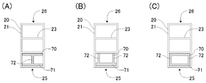
- the reinforcing means is a reinforcing member that is inserted into a space surrounded by the bending inner portion of the peripheral wall and the first partition wall and extends in the longitudinal direction of the peripheral wall.
- the reinforcing member has a thickness of 0.8 to 3.0 mm, a backing surface that is in contact with an inner portion of the peripheral wall, and is parallel to the bending plane and continuous from the backing surface. And a leg formed.
- a ratio H (mm) / t o (mm) between a cross-sectional height (H) of the core material and a thickness (t o ) of the peripheral wall in an outer portion of the bending process is 18.0 or less.
- the cross-sectional height (H) of the core material is two parallel straight lines that sandwich the outer shape of the core material in a cross section perpendicular to the longitudinal direction of the core material, and is parallel to the bending plane. The distance.
- the ratio of the cross-sectional height (H) of the core material to the bending radius of curvature (R), H (mm) / R (mm), is 0.09 or less.
- the bending radius refers to the radius of curvature of the inner part of the bent product.
- the value of the portion with the smallest radius of curvature is used.
- the core material is made of aluminum.
- the term “aluminum” includes aluminum alloy in its category.
- the coating layer contains at least a thermoplastic resin and wood powder.
- the thermoplastic resin contained in the coating layer is a polyolefin resin.
- the coating layer has a thickness of 0.1 to 5 mm.
- the bent product further has an adhesive layer formed between the core material and the coating layer.
- the adhesive layer contains at least a copolymer of an ⁇ -olefin and an epoxy group-containing unsaturated monomer.
- the thickness of the adhesive layer is 0.05 to 1.0 mm.
- the cross-sectional shape of the core material is substantially rectangular.
- the bent product 10 of this embodiment is bent with a radius of curvature R around the bending center O.
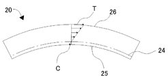
- the bending plane P is a plane on which the central axis A in the longitudinal direction of the bent product 10 is placed. In this figure, the bending plane P coincides with the paper surface.
- the side closer to the bending center O is referred to as the inner side 25 of the bending process, and the side far from the bending center O is referred to as the outer side 26 of the bending process.
- FIG. 10B is a BB end view of FIG. 10A, showing a cross section perpendicular to the longitudinal direction of the bent product.
- cross section means a cross section perpendicular to the longitudinal direction of the bent product and the core material.
- the hatched portion is the peripheral wall 21 of the core material 20, and the partition material inside the core material is omitted.
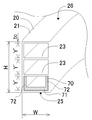
- the distance between two straight lines h and h that are parallel two straight lines sandwiching the outer shape of the cross-sectional shape and are substantially orthogonal to the bending plane is referred to as a cross-sectional height H of the core material 20.
- the distance between two straight lines w and w that are parallel two straight lines sandwiching the outer shape of the core material and are parallel to the bending plane is referred to as a cross-sectional width W of the core material 20.
- the cross-sectional height H and the cross-sectional width W of the core material are determined by the relationship with the bending direction of the core material.
- the long diameter of the cross section is the long side when the cross section is rectangular, the long diameter when the cross section is elliptical, and the outer periphery when the cross section is irregularly shaped This is the distance of the longest parallel straight line.
- the short axis of the cross section is the short side when the cross section is a rectangle, the short diameter when the cross section is an ellipse, and the parallel across the outer periphery when the cross section is an irregular shape. This distance is the shortest distance between two straight lines.
- the cross section is a rectangle, the long diameter coincides with the cross section width W, and the short diameter coincides with the cross section height H.
- the major axis and minor axis of the core material are determined based on the cross-sectional shape of the core material.
- the cross section shows a cross section perpendicular to the longitudinal direction of the core material, the lower side of the figure is the inside of the bending process, that is, the side where the bending curvature is smaller, and the upper side of the figure is the outside of the bending process Is shown.
- a coating layer 40 is formed on the outer surface of a hollow core member 20 via an adhesive layer 30.
- the core material 20 of the present embodiment has a tubular peripheral wall 21 having a rectangular cross section, and two partition walls 23 extending in the longitudinal direction of the core material by dividing the internal space of the peripheral wall in the major axis direction of the cross section.
- the coating layer 40 contains at least a thermoplastic resin.
- the bent product 10 is bent in a plane parallel to the partition wall 23 (in the bending plane), with the lower side of the figure as the inner side 25 of the bending process and the upper side of the figure as the outer side 26 of the bending process.
- the major axis in the cross section perpendicular to the longitudinal direction of the core material is orthogonal to the bending plane P, and the minor axis is parallel to the bending plane P.
- the partition wall 23 serves as a reinforcing means against the appearance failure (shape failure) of the inner wall 25 of the peripheral wall 21 due to compression deformation.
- first partition wall what divides the internal space of the peripheral wall in the major axis direction of the cross section
- second partition wall what divides the internal space of the peripheral wall in the minor axis direction of the cross section.
- the partition wall 23 of this embodiment is a first partition wall.
- the span Y and the thickness t R of the partition wall are used for the first partition wall or the second partition wall, which is a reinforcing means against deformation caused by bending unless otherwise specified.
- the core material 20 is made of aluminum or an aluminum alloy. Specifically, grades having good extrudability such as those used for aluminum sashes, for example, materials such as alloy numbers 6063 and 6060 of JISH4100 are used.
- the thickness t of the peripheral wall 21 of the core material 20 is 0.8 mm to 2.3 mm. If the peripheral wall is too thin, poor appearance tends to occur at the time of bending, and production stability is inferior at the time of manufacturing a core material by extrusion molding of aluminum. Moreover, when a surrounding wall is too thick, lightness etc. will be impaired. From these points, the thickness t of the peripheral wall is preferably 1.0 to 1.9 mm, and more preferably 1.2 to 1.8 mm.
- bending the thickness of the inner portion 25 of the machining t i, bending of the thickness of the outer portion 26 is represented by t o.
- the thicknesses t i and t o may be different, it is preferable that the thickness t of the peripheral wall 21 is equal over the entire circumference from the viewpoint of productivity of the core material.
- the thickness t R of the partition wall 23 of the core member 20 is preferably 0.8 mm to 2.3 mm. If the partition wall is too thin, the production stability is inferior when the core material is manufactured by extrusion molding of aluminum. Moreover, when a partition wall is too thick, lightness etc. will be impaired. From these points, the thickness t R of the partition wall is more preferably 0.9 to 1.9 mm, and particularly preferably 1.0 to 1.8 mm.
- the span Y of the partition wall 23 is a parallel straight line that sandwiches the internal space divided by the partition wall in a cross section perpendicular to the longitudinal direction of the core member 20, and is two straight lines parallel to the partition wall. Say distance.
- the bending ratio of the peripheral wall thickness t i in the inner portion of the processing, Y (mm) / t i (mm) is required to be at 12.0 or less, it is 10.0 or less Is preferable, and it is more preferable that it is 9.0 or less.
- the ratio Y / t i is smaller, the inner side of the processed portion is less likely to be generated during bending as described later.
- the lower limit of Y / t i is not particularly limited, but Y / t i is preferably 5.0 or more in consideration of the reinforcing effect of the partition wall 23, the weight of the bent product 10, and the material cost. More preferably, it is 0.0 or more.
- the cross-sectional height H of the core member 20 is two parallel straight lines sandwiching the outer shape of the core member in a cross section perpendicular to the longitudinal direction of the core member, and is two straight lines perpendicular to the partition wall 23. Distance.
- the height in the vertical direction of the core material in FIG. The ratio of the cross-sectional height H of the core material to the thickness t o of the peripheral wall 21 at the outer portion of the bending process, H (mm) / t o (mm) is preferably 18.0 or less, and 16.0 or less. More preferably, it is particularly preferably 14.0 or less. The larger the ratio H / t o is small, as described later, bent processed part outer coating layer surface during processing of the linear defect or hairline-like defects is unlikely to occur.
- H / t o is not particularly limited, the weight of the bending processed article 10, considering the material cost, it is preferred that H / t o is 10.0 or more, 15.0 or more Further preferred.
- the ratio of the cross-sectional height H of the core material to the radius of curvature R of the bending process, H (mm) / R (mm) is preferably 0.09 or less, more preferably 0.07 or less, and 0 .05 or less is particularly preferable. As the ratio H / R is smaller, as will be described later, a linear defect or a hairline defect is less likely to occur on the surface of the coating layer outside the processed part during bending.
- H / R is not specifically limited, In order to obtain the aesthetic effect by a bending process, it is preferable that it is 0.005 or more, and it is further more preferable that it is 0.010 or more.
- the overall dimensions of the core material 20 are not particularly limited other than those described above, and may be set as appropriate according to the application of the obtained bent product.
- the cross-sectional height H of the core material and the cross-sectional width W in the direction orthogonal to the height are preferably 20 mm or more, more preferably 30 mm or more.
- the core material 20 when the integrally extruded body is bent, the core material 20 has a compressive stress C at the inner portion 25 of the bending process, with the neutral surface 24 having a length not changed by bending deformation as a boundary.
- a tensile stress T is generated at the outer portion 26.
- the coating layer and adhesive layer made of resin are more flexible than metals such as aluminum, so they easily follow deformation, but the adhesion between the core material and the adhesive layer and / or the coating layer is broken even if the peripheral wall does not buckle. Then, wrinkles are generated on the surface of the coating layer. Further, when a powder such as wood flour is added to the coating layer, wrinkles are more likely to occur.
- the absolute amount of elongation of the peripheral wall 21 and the coating layer 40 outside the bent portion depends on the ratio H / R.
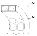
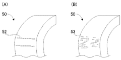
- the ratio H / R is 0.09 or less, appearance defects such as hairline defects shown in FIG. 4B are less likely to occur.
- the ratio Y / t i is important in the above range. Further, the bending disadvantage of the processing member outer, less likely to occur than the inner disadvantage, but the order to prevent this, it is preferable to set the ratio H / t o the above range. Further, the ratio H / R is preferably set in the above range.
- the ratio Y / t min and the ratio H / t min are within the above ranges with respect to the minimum value t min of the thickness t of the peripheral wall 21. It is preferable to do. This is because the direction of bending is not limited. Further, the ratio H / R is preferably set in the above range.
- the core material 20 is subjected to knurling treatment and / or before the formation of the coating layer 40 or the adhesive layer 30 described later for the purpose of further improving the adhesion with the coating layer 40 or the adhesive layer 30.
- An anodizing treatment is preferably performed. When performing both the knurling process and the anodizing process, it is preferable to perform the anodizing process after the knurling process.
- the knurling process is a process for forming a groove on the outer surface of the core material, whereby the adhesion between the coating layer or the adhesive layer and the core material is further improved.
- the core material may have a groove along the longitudinal direction at least in the coating layer or adhesive layer forming region on the outer surface.
- the core material may have the groove only in the covering layer or the adhesive layer forming region, or may have the groove in a region other than the covering layer or the adhesive layer forming region. From the viewpoint of adhesion to the coating layer or the adhesive layer, preferably, for example, as shown in FIG. 2, the groove 22 is formed on the entire outer surface of the core member 20.
- the groove 22 When the groove 22 is formed along the longitudinal direction of the core material, the groove can be applied simultaneously with the molding of the core material, and more uniform groove formation can be achieved efficiently.
- the present invention does not prevent the core material from having, for example, a groove in a direction substantially perpendicular to the longitudinal direction or unevenness due to embossing in addition to the groove in the longitudinal direction of the core material. It is preferable to have only longitudinal grooves. This is because it is possible to ensure good adhesion between the core material and the coating layer or the adhesive layer only by having the longitudinal grooves.
- the depth d of the groove 22 by knurling is preferably 0.03 to 1.0 mm, more preferably 0.05 to 0.35 mm.
- the pitch p of the groove 22, that is, the deepest part interval between adjacent grooves is preferably 0.03 to 1.5 mm, more preferably 0.05 to 1.0 mm.
- the depth d and the pitch p of the groove are shown as average values of values measured at arbitrary three locations per 1 m in the longitudinal direction of the core material.
- the measurement method is not particularly limited, but a method using a micro gauge is simple. Further, the depth may be measured by irradiating a laser beam. The depth and pitch can also be measured by a method of confirming the cut section with a microscope.
- the shape of the groove 22 is not particularly limited, and, for example, the cross-sectional shape of the unevenness formed by the groove has a form in which substantially triangular convex portions and concave portions are continuous as shown in FIG. Or may have a form in which substantially arc-shaped convex portions and concave portions are continuous.
- the anodizing treatment is a treatment for forming an oxide film on the surface of the metal core material, and the principle of a general anodizing treatment method can be employed as it is. This further improves the adhesion between the coating layer or adhesive layer and the core material.
- the anodizing treatment of the aluminum core material is particularly called alumite treatment.
- sealing treatment may be performed as a post process.
- the sealing treatment is for preventing adverse effects such as a decrease in corrosion resistance due to the fine pores generated by the anodizing treatment, and a treatment in pressurized water vapor or a treatment in an aqueous solution of nickel acetate / cobalt acetate is used. ing.
- those in the stage where the sealing treatment is not performed are preferably used as the core material. This is because the adhesive force with the coating layer or the adhesive layer is greatly improved due to the fine pores on the surface of the oxide film.
- the coating layer 40 is a resin layer containing at least a thermoplastic resin as a base resin.
- polyolefin resin is preferable.
- the polyolefin resin is a homopolymer or copolymer containing one or more ⁇ -olefins as monomers.
- the ⁇ -olefin include ⁇ -olefins having 2 to 8, preferably 2 to 6 carbon atoms such as ethylene, propylene, isobutylene and hexene.
- Preferred ⁇ -olefins are ethylene and propylene.
- the polyolefin resin may contain a monomer other than ⁇ -olefin as a monomer. Examples of such other monomers include vinyl ester monomers such as vinyl acetate.
- polyolefin resins include polyolefins such as polyethylene, polypropylene, and ethylene-propylene copolymers, and ethylene vinyl acetate copolymers.
- Preferred polyolefin-based resins are polyolefins, particularly polyethylene and polypropylene.
- the polyolefin resin is preferably modified with an unsaturated carboxylic acid. Since the unsaturated carboxylic acid-modified polyolefin resin has a relatively high compatibility with the wood flour in the coating layer, the adhesion between the coating layer and the adhesive layer can be further improved.
- An unsaturated carboxylic acid is a compound having one or more unsaturated bonds and one or more carboxyl groups in one molecule.
- Specific examples of the unsaturated carboxylic acid include unsaturated monocarboxylic acids such as acrylic acid, methacrylic acid, ethacrylic acid and crotonic acid, unsaturated dicarboxylic acids such as itaconic acid, maleic acid and fumaric acid, and derivatives thereof.
- Unsaturated carboxylic acid derivatives include the chlorides, amides, esters and anhydrides of the acids mentioned above. Examples of the acid ester include methyl ester, ethyl ester, propyl ester, and dimethylaminoethyl ester.
- Preferred unsaturated carboxylic acids are unsaturated dicarboxylic acids and anhydrides, and specific examples thereof include maleic acid and maleic anhydride.
- Modification with an unsaturated carboxylic acid can be achieved by adding an unsaturated carboxylic acid to the system during or after the polymerization of the polyolefin resin.
- the unsaturated carboxylic acid-modified polyolefin resin has a form in which an unsaturated carboxylic acid is incorporated into the main chain of the polyolefin resin by an addition reaction, and a chemical bond is formed between the polyolefin resin and the unsaturated carboxylic acid. And may have a form in which the unsaturated carboxylic acid is dispersed in the polyolefin resin without forming a chemical bond between the polyolefin resin and the unsaturated carboxylic acid. Or may have a combination of these forms.
- the content of the unsaturated carboxylic acid in the unsaturated carboxylic acid-modified polyolefin resin is 0.1 to 15% by weight, particularly 0.1 to 10% by weight, based on the total monomers of the unsaturated carboxylic acid-modified polyolefin resin.
- Two or more kinds of unsaturated carboxylic acids may be contained, and in that case, the total amount thereof may be within the above range.
- the polyolefin resin preferably has a melting point of 165 ° C. or lower, particularly 125 to 165 ° C.
- the MFR (melt flow rate) of the polyolefin resin is preferably 3 to 25 g / 10 min, and more preferably 3 to 15 g / 10 min.
- the melting point can be measured using a commonly used differential scanning calorimeter, for example, when a sample of about 5 mg is measured at a heating rate of 10 ° C./min in a nitrogen atmosphere. It can be determined by measuring the peak value of the endothermic peak accompanying the phase transition.
- MFR is a value at 190 ° C. and a load of 2.16 kgf, and can be measured based on JISK7210.
- the polyolefin-based resin can be produced by a conventionally known method such as a suspension polymerization method or a solution polymerization method, or can be obtained as a commercial product.
- the polyolefin as the polyolefin-based resin can use a recycled product derived from a discarded polyolefin product. This is preferable because the environmental load is reduced.
- Umex 1010 manufactured by Sanyo Chemical Industries
- the coating layer may contain an unsaturated carboxylic acid as another component of the above-described polyolefin resin.
- Unsaturated carboxylic acid contained as a separate component of polyolefin resin can increase the compatibility between polyolefin resin and wood flour, and as a result, it can further improve the adhesion between the coating layer and the adhesive layer. it can.
- adding an unsaturated carboxylic acid as another component of the polyolefin to the coating layer is effective from the viewpoint of further improving the adhesion between the coating layer and the adhesive layer.
- the unsaturated carboxylic acid contained as another component of the polyolefin resin the same compounds as the unsaturated carboxylic acid of the unsaturated carboxylic acid-modified polyolefin resin described above can be used, and the preferred unsaturated carboxylic acid is an unsaturated dicarboxylic acid. Specific examples thereof include maleic acid and maleic anhydride.
- the content of the unsaturated carboxylic acid contained as another component of the polyolefin resin is preferably 0.2 to 10% by weight, more preferably 1.0 to 10% by weight, based on the polyolefin resin. Two or more kinds of unsaturated carboxylic acids may be contained, and in that case, the total amount thereof may be within the above range.
- the present invention does not prevent the base resin from containing other resins than the polyolefin resin.
- the other resin include acrylonitrile butadiene styrene resin.
- Wood powder is preferably added to the coating layer in order to give an excellent appearance and feel.
- wood flour wood such as cedar, cypress, and baitsuga, and crushed and waste wood such as wood, sawdust, etc. are often used, and those having a particle size of 10 to 500 mesh should be used. Although it is possible, it is more preferably about 60 to 100 mesh. It is preferable to use milled wood and waste material as wood powder because the environmental load is reduced.
- the content of wood powder is 5 to 50 parts by weight, preferably 10 to 40 parts by weight, based on 100 parts by weight of the polyolefin resin.
- the coating layer may be a single layer type or a multilayer type of two or more layers.
- the multilayer coating layer may be integrally formed with two or more coating layers in the above-described range.
- the thickness of the coating layer is not particularly limited as long as the object of the present invention is achieved, and is preferable from the viewpoints of adhesiveness, appearance, and productivity, and because it does not cause hairline defects on the surface during bending. Is 0.1 to 5 mm. From the viewpoint of further improving the texture of the wood when touched and the adhesion of the coating layer, the thickness of the coating layer is preferably 0.6 to 3.0 mm, particularly preferably 1.0 to 2.0 mm. When a coating layer is a multilayer type, those total thickness should just be in the said range.
- the covering layer may have a form of a so-called non-foamed body or a low foamed body having a foaming ratio of 5 times or less, particularly 2 times or less.
- additives conventionally used in synthetic resins such as colorants, fillers, UV absorbers, antistatic agents, matting agents, seeds, mica powder, to improve various physical properties of the coating layer Body, organic fiber, vermiculite powder, glass chip, waste paper powder, ceramic powder and the like may be contained.
- colorant known inorganic or organic pigments can be used.
- the content of the colorant is preferably 1 to 4% by weight based on the polyolefin resin.
- the filler for example, calcium carbonate, talc and the like can be used.
- the filler content is preferably 5 to 40% by weight based on the polyolefin resin.
- an adhesive agent will not be specifically limited if it has adhesive force with respect to resin which is aluminum and a coating layer.
- an adhesive layer of an elastic adhesive is preferably provided between the core material 20 and the coating layer 40.
- an adhesive may be applied in advance to the surface of the core material by spraying, dipping, or the like, and may be integrally extruded with the coating layer.
- the adhesive layer 30 of the present embodiment is a resin layer containing a polyolefin-based resin containing epoxy.
- a polyolefin-based resin containing epoxy is a copolymer obtained by polymerizing at least an ⁇ -olefin and an epoxy group-containing unsaturated monomer.
- the adhesiveness between the adhesive layer and the coating layer and the adhesiveness between the adhesive layer and the core material are improved, and as a result, the adhesiveness of the coating layer to the core material is improved.
- the adhesion between the adhesive layer and the coating layer is improved because the epoxy group in the adhesive layer reacts with the hydroxyl group of the cellulose constituting the wood powder in the coating layer to form a chemical bond (ether bond). It is considered to be achieved.
- the effect of further improving the adhesion between the adhesive layer and the coating layer obtained by containing the unsaturated carboxylic acid in the coating layer is that the epoxy group in the adhesive layer is carboxylated in the unsaturated carboxylic acid in the coating layer. This is considered to be achieved because a chemical bond (ester bond) is formed by reacting with a group.
- Examples of the ⁇ -olefin constituting the epoxy group-containing polyolefin resin include the same monomers as the ⁇ -olefin constituting the polyolefin resin.
- Preferred ⁇ -olefins are ethylene and propylene.
- the epoxy group-containing unsaturated monomer is a compound having one or more unsaturated bonds and one or more epoxy groups in one molecule, and examples thereof include glycidyl (meth) acrylate such as glycidyl acrylate and glycidyl methacrylate. Of these, glycidyl (meth) acrylate is preferred. Glycidyl (meth) acrylate is meant to include glycidyl acrylate and glycidyl methacrylate.
- the epoxy group-containing polyolefin resin may contain a monomer other than the ⁇ -olefin and the epoxy group-containing unsaturated monomer as a monomer.
- examples of such other monomers include vinyl ester monomers such as vinyl acetate; acrylic monomers such as methyl acrylate, ethyl acrylate, propyl acrylate, methyl methacrylate, ethyl methacrylate, and propyl methacrylate; styrene and the like And styrene monomers such as vinyl chloride monomers such as vinyl chloride.
- the 1 or more types of monomer selected from the group which consists of a vinyl ester monomer and an acrylic monomer is used, More preferably, a vinyl ester monomer or an acrylic monomer is used.
- a preferred vinyl ester monomer is vinyl acetate.
- a preferred acrylic monomer is methyl acrylate.
- epoxy group-containing polyolefin resin examples include, for example, the following copolymers. (1) ⁇ -olefin-epoxy group-containing unsaturated monomer copolymer; (2) ⁇ -olefin-epoxy group-containing unsaturated monomer-vinyl ester monomer copolymer; (3) ⁇ -olefin-epoxy group-containing unsaturated monomer-acrylic monomer copolymer; (4) ⁇ -olefin-epoxy group-containing unsaturated monomer-styrene monomer copolymer; (5) ⁇ -olefin-epoxy group-containing unsaturated monomer-halogenated vinyl monomer copolymer; (6) ⁇ -olefin-epoxy group-containing unsaturated monomer-vinyl ester monomer-acrylic monomer copolymer.
- the copolymers of (1), (2), (3) and (6) are preferred, the copolymers of (1), (2) and (3) are more preferred, The copolymer (2) is preferred.
- the content of ⁇ -olefin in the epoxy group-containing polyolefin-based resin is 60% relative to the total monomer component of the resin from the viewpoint of improving the adhesiveness between the coating layer and the adhesive layer and the adhesiveness between the adhesive layer and the core material. Is preferably 95% by weight, more preferably 75% to 90% by weight. Two or more ⁇ -olefins may be used in combination, and in this case, the total amount of the ⁇ -olefins may be within the above range.
- the content of the epoxy group-containing unsaturated monomer in the epoxy group-containing polyolefin-based resin is based on the total monomer component of the resin from the viewpoint of improving the adhesion between the coating layer and the adhesive layer and the adhesion between the adhesive layer and the core material.
- the content is preferably 3 to 30% by weight, more preferably 10 to 20% by weight.
- Two or more kinds of epoxy group-containing unsaturated monomers may be used in combination, and in that case, the total amount thereof may be within the above range.
- the content of the other monomer in the epoxy group-containing polyolefin-based resin is preferably 30% by weight or less, more preferably 10% by weight or less, based on all monomer components of the resin. Two or more kinds of other monomers may be used in combination, and in that case, the total amount thereof may be within the above range.
- the epoxy group-containing polyolefin resin preferably has a melting point of 50 to 105 ° C., particularly 90 to 100 ° C., from the viewpoint of heat resistance and extrusion moldability.
- the MFR of the epoxy group-containing polyolefin resin is preferably 1 to 20 g / 10 min, and more preferably 3 to 10 g / 10 min.
- the epoxy group-containing polyolefin resin can be produced by a conventionally known method such as a suspension polymerization method or a solution polymerization method, or can be obtained as a commercial product.
- the present invention does not prevent the adhesive layer from containing other resins than the epoxy-containing polyolefin resin within a range that does not impair the adhesiveness.
- the thickness of the adhesive layer is not particularly limited as long as the object of the present invention is achieved. From the viewpoint of adhesiveness and productivity, and in order not to cause breakage, peeling or the like in the adhesive layer at the time of bending, it is preferably 0.00.
- the thickness is from 05 to 1.0 mm, more preferably from 0.1 to 0.5 mm.
- the integral extruded body of this embodiment can be manufactured as follows.
- the aluminum core material can be manufactured by extrusion molding of aluminum or aluminum alloy.
- the integrally extruded body is manufactured by a so-called integral extrusion method in which the coating layer is integrated with the core material simultaneously with the extrusion molding of the coating layer from the viewpoints of productivity, long product molding, and constant product characteristics.
- an adhesive may be applied in advance to the surface of the core material by spraying, dipping, or the like, and may be integrally extruded with the coating layer.
- the core material, the adhesive layer, and the coating layer may be integrally extruded.
- a coextrusion type integrated extruder as shown in FIG.
- the resin extruded from the extruders 60 and 61 for melting and kneading the material forming each resin layer is laminated in the die 62. At the same time, these layers are sequentially covered and integrated with the fed core material 20. Once integrated, it is usually cooled and cut to the desired dimensions.
- two extruders are used in FIG. 6, the present invention is not limited to this, and may be installed as appropriate according to the number of coating layers.
- the bending of the integrally extruded body can be performed at room temperature by a known method such as roll bending, press bending, or a method of bending a material while pressing the material against a bending mold using a so-called bender.
- FIG. 11 shows only the core material.
- the lower side of the figure shows the inner side 25 of the bending process
- the upper side of the figure shows the outer side 26 of the bending process.
- the coating layer 40 is formed on the outer surface of the core member 20 via the adhesive layer 30 in the bent product of the present embodiment as in the first embodiment.
- the core member 20 has a tubular peripheral wall 21 having a rectangular cross section, and two first partition walls 23 that divide the internal space of the peripheral wall in the major axis direction of the cross section and extend in the longitudinal direction of the core member.
- the core member 20 of the present embodiment further has a second partition wall 27 that divides the internal space of the peripheral wall in the minor axis direction of the cross section.
- the major axis in the cross section perpendicular to the longitudinal direction of the core material 20 is parallel to the bending plane P, and the minor axis is orthogonal to the bending plane P.
- the first partition wall 23 has a reinforcing function against deformation at the time of integral extrusion, and the inner portion 25 mainly causes a defective appearance (defective shape) due to compression deformation when the second partition wall 27 is bent. Reinforcing function.
- the bent product 10 of the present embodiment has a core material and thickness; presence / absence of knurling processing of the core material, processing mode; presence / absence of processing of the core material, processing mode; material and thickness of the coating layer; adhesion
- the same as in the first embodiment can be suitably selected for the presence / absence of the layer, the material, and the thickness.
- the ratio between the thickness t i of the circumferential wall in the inner portion of the bending and span Y of the second partition wall 27, and a preferred range and the reason of Y (mm) / t i ( mm) is the same as in the first embodiment is there. Further, the ratio of the cross-sectional height H of the core material 20 to the thickness t o of the peripheral wall in the outer portion of the bending process, the preferable range of H (mm) / t o (mm) and the reason thereof are the same as those in the first embodiment. The same. Further, the ratio between the cross-sectional height H of the core material and the bending radius of curvature R, the preferable range of H (mm) / R (mm), and the reason thereof are the same as those in the first embodiment.
- the ratio Y / t min and the ratio H / t min are within the above ranges with respect to the minimum value t min of the thickness t of the peripheral wall 21. It is preferable to do. This is because the direction of bending is not limited.
- the ratio H / R is more preferably within the above range.
- the second partition wall 27 of the present embodiment is not formed from the bent inner portion 25 to the outer portion 26 of the peripheral wall 21 as shown in FIG. 11, but as shown in FIG. A space provided between the bending inner portion and the first partition wall 23 and surrounded by the bending inner portion of the peripheral wall and the first partition wall may be provided so as to be divided in the minor axis direction.
- the 1st partition wall 23 in this embodiment needs to be formed ranging from a part of surrounding wall to the part facing it. Further, as described in Patent Document 2, there is a preferable range for the ratio between the span Y ′ of the first partition wall 23 and the thickness t ′ of the peripheral wall of the portion where the first partition wall continues.
- the cube of Y ′ (mm) / t ′ (mm) is preferably 5000 or less, more preferably 2500 or less, and 1500. It is particularly preferred that Further, considering the cost of the core material, the cube of Y ′ (mm) / t ′ (mm) is preferably 200 or more, and more preferably 400 or more.
- the bent product of this embodiment is manufactured by extruding the core material 20, integrally extruding the core material and the coating layer, and bending the obtained integrally extruded product, as in the first embodiment. can do.
- FIG. 13 shows only the core material and the reinforcing member.
- the lower side of the figure shows the inner side 25 of the bending process
- the upper side of the figure shows the outer side 26 of the bending process.
- the coated layer 40 is formed on the outer surface of the core material 20 via the adhesive layer 30 in the bent product of the present embodiment as in the first and second embodiments.
- the core member 20 has a tubular peripheral wall 21 having a rectangular cross section, and two first partition walls 23 that divide the internal space of the peripheral wall in the major axis direction of the cross section and extend in the longitudinal direction of the core member.
- the bent product 10 according to the present embodiment is further inserted into a space surrounded by the bent inner side portion of the peripheral wall and the first partition wall, that is, inserted with no gap and has a cross section extending in the longitudinal direction of the peripheral wall.
- a reinforcing member 70 having a U-shape is provided.
- the major axis in the cross section perpendicular to the longitudinal direction of the core material 20 is parallel to the bending plane P, and the minor axis is orthogonal to the bending plane P.
- the first partition wall 23 has a reinforcing function against deformation at the time of integral extrusion, and mainly the reinforcement against the appearance failure (defective shape) of the inner portion 25 due to compression deformation when the reinforcing member 70 is bent. It has a function.
- the bent product 10 of the present embodiment has a core material and thickness; presence / absence of knurling processing of the core material, processing mode; presence / absence of processing of the core material, processing mode; material and thickness of the coating layer; adhesion
- the same as in the first and second embodiments can be suitably selected for the presence / absence of layer, material, and thickness.
- the ratio between the cross-sectional height H of the core material 20 and the thickness t o of the peripheral wall in the outer portion of the bending process, the preferable range of H (mm) / t o (mm) and the reason thereof are the first and second embodiments. Is the same. Further, the ratio between the cross-sectional height H of the core material and the radius of curvature R of the bending process, the preferable range of H (mm) / R (mm), and the reason thereof are the same as those in the first and second embodiments.
- the reinforcing member 70 it is preferable to use aluminum or an aluminum alloy like the core material 20. Specifically, grades with good extrudability such as those used for aluminum sashes, for example, materials such as alloy numbers 6063 and 6060 of JISH4100 are preferable.
- the reinforcing member 70 extends in the longitudinal direction of the bent product, like the core material.
- the reinforcing member of FIG. 13 has a U-shaped cross section, and has a backing surface 71 that abuts the inner portion 25 of the peripheral wall 21 that is bent, and two leg portions 72 that are bent and extend from both ends thereof. The other end of the leg abuts on the first partition wall 23.
- the backing surface comes into contact with the inner portion of the peripheral wall from the inner space side, and counteracts the force that the peripheral wall tends to deform by the backing surface and the leg portion, thereby preventing appearance defects.
- the reinforcing member 70 is mainly a reinforcing means for preventing the appearance defect from occurring in the inner wall portion 25 of the peripheral wall.
- the shape of the reinforcing member 70 is not limited to a U-shaped cross section, and may be various shapes shown in FIG. In any case, it has a backing surface 71 that comes into contact with the inner portion of the peripheral wall 21 during bending, and two leg portions 72 that are bent and extended from both ends thereof. Of these, a U-shaped cross section is preferable from the viewpoint of ease of manufacture and cost.
- the size of the reinforcing member 70 needs to fit into the inserted internal space. If the play is too large when the reinforcing member is inserted into the internal space, the inner portion of the peripheral wall will be deformed during bending. Therefore, the play when the reinforcing member is inserted into the internal space is preferably 1.0 mm or less, and more preferably 0.5 mm or less.
- the thickness of the reinforcing member 70 is 0.8 mm to 3.0 mm. If the reinforcing member is too thin, the reinforcing effect is insufficient, and the production stability is inferior when the core material is manufactured by extrusion molding of aluminum. Moreover, when a reinforcement member is too thick, lightweight property etc. will be impaired. From these points, the thickness of the reinforcing member is preferably 1.0 to 2.3 mm, more preferably 1.2 to 1.8 mm.
- the 1st partition wall 23 in this embodiment is the ratio of span Y 'of the 1st partition wall 23, and thickness t' of the surrounding wall of the part where a 1st partition wall continues similarly to that of 2nd Embodiment.
- Y ′ (mm) / t ′ (mm) is preferably 5000 or less, more preferably 2500 or less, and particularly preferably 1500 or less.
- the cube of Y ′ (mm) / t ′ (mm) is preferably 200 or more, and more preferably 400 or more.
- the bent product of this embodiment can be manufactured as follows. First, the core material 20 is extruded, and the core material and the coating layer are integrally extruded.
- the reinforcing member 70 is fitted and inserted into a space surrounded by the peripheral wall 21 and the first partition wall 23 that are the inner side 25 of the bending process on the obtained integrally extruded body. Next, the integrally extruded body containing the reinforcing member is bent.
- a hollow aluminum core material having a substantially rectangular cross section as shown in FIG. 2 was produced by extrusion molding.
- the number of partition walls was 1, 2, 3 or 6 depending on the examples and comparative examples.
- a groove extending in the longitudinal direction was formed on the aluminum core material by knurling, and then an oxide film was formed by alumite treatment (without sealing treatment).
- the material of the aluminum alloy was an extrusion grade alloy number 6063.
- the plate groove pitch was 0.5 mm and the groove depth was 0.1 mm.
- the alumite treatment used the sulfuric acid method.
- the pellet for the coating layer is composed of 100 parts by weight of maleic acid-modified polypropylene resin (maleic acid content: about 2% by weight, melting point: 150 ° C., MFR: about 10 g / min), 30 parts by weight of wood flour (particle size: 100 mesh or less), Brown part coloring agent 5.2 weight part and filler (talc) 15 weight part were mixed. The mixture was melted and extruded, then cooled and coarsely crushed to produce pellets.
- Bondfast (registered trademark) 7B manufactured by Sumitomo Chemical Co., Ltd., ethylene-glycidyl methacrylate-vinyl acetate (copolymerization ratio (weight ratio) 83: 12: 5)
- MFR 7 g is used for the adhesive layer. / 10 min, melting point 95 ° C.).
- An integrally extruded body was produced by a coextrusion type integral extruder as shown in FIG.
- the covering layer material and the adhesive layer material are simultaneously extruded from the extruder 60 and the extruder 61, respectively, laminated and coated on the aluminum core material 20 in the die 62, and all the circumferential direction on the outer surface of the aluminum core material.
- a monolithic extruded product having an adhesive layer and a coating layer was produced. Extrusion conditions and core material conditions are as follows.
- Extruder 60 40 ⁇ , single screw extruder (extrusion temperature about 140 ° C)
- Extruder 61 50 ⁇ , single screw extruder (extrusion temperature about 165 ° C)
- the aluminum core was preheated (about 100 ° C.) immediately before being inserted into the die.
- Examples 1 to 5 and Comparative Examples 1 to 10 the manufactured integrally extruded bodies were bent as they were by roll bending so that the major axis direction of the cross section was perpendicular to the bending plane, thereby producing bent molded articles.
- a reinforcing member having a U-shaped cross section is inserted into the manufactured integrally extruded body in the direction shown in FIG. 13, and the major axis direction of the cross section is the bending plane by roll bending. Bending was performed so as to be parallel, and a bent molded product was produced.
- the reinforcing members used in Examples 6 and 7 were produced by extrusion molding of aluminum, and the backing surface had a thickness of 2.3 mm and the leg portions had a thickness of 1.5 mm.
- the appearance of the obtained bent product was visually evaluated.
- the evaluation criteria were as follows. About the inside of the bending part ⁇ : Appearance good; ⁇ : Slight wrinkles are observed on the surface of the coating layer; X: The core material has a dent. About the outside of the bent part ⁇ : Appearance good; ⁇ : Slight hairline defects are observed on the surface of the coating layer; X: A linear groove is observed on the surface of the coating layer.
- Table 1 shows the dimensions, bending radii, and appearance evaluation results of the integrally extruded product.
- Examples 1 to 5 a good appearance was obtained.
- Comparative Examples 1 to 7 a dent was observed inside the bent portion.
- Comparative Examples 8 to 10 the thickness of the peripheral wall differs between the inner part and the outer part of the bending process.
- the appearance of the inner part of the bending process was good, but the peripheral wall thickness was large, which was not preferable because the lightness and workability were impaired.
- the defect of the hairline shape was recognized by the outer side part of the bending process. As a cause of this, since the thickness t i of the peripheral wall of the inner part of the bending process is as large as 3.5 mm, the neutral surface (24 in FIG. 5) during the bending process may have moved to the inner side.
- the span Y with respect to the partition wall is not conceived.
- the span Y and the ratio Y / t with respect to the first partition wall are shown in the table for reference.
- six bent products having bending radii R of 1007, 1081, 1155, 1229, 1303, and 1377 mm were produced, respectively, and good appearance was obtained in all cases.
- the cross-sectional shape of the core material is not limited to a rectangle, and may be a substantially circular shape, a substantially oval shape, a substantially square shape, or the like.
- the span Y of the partition wall is similarly defined as the distance between two straight lines parallel to the partition wall that sandwich the internal space divided by the partition wall in the cross section perpendicular to the longitudinal direction of the core material.
- the cross section is circular, one of the diameters parallel to or perpendicular to the bending plane may be considered as the major axis and the other as the minor axis.
- any one of the sides may be considered as a major axis and a side adjacent to the major axis may be considered as a minor axis.
- the core material may have a portion protruding outside the peripheral wall.
- the cross-sectional height H of the core material can be similarly defined as the distance between two straight lines perpendicular to the bending plane that sandwich the outer shape of the core material in a cross-section perpendicular to the longitudinal direction of the core material (see FIG. 8).
- the thicknesses t, t i , and t o of the peripheral wall are not uniform and may be locally different.
- t, Y / t i, and H / t o should just exist in the prescribed
- a part of the peripheral wall may have a locally thick part for screwing or the like.
- the thickness t of the peripheral wall means the thickness of the part excluding the locally thick part. .
- the number of partition walls is not particularly limited, and the shape thereof may be formed so as to intersect so that the cross section has a lattice shape as shown in FIG.
- Y, t i , H, and t o are defined according to the bending direction, so Y / t i and H / t o need only be within the range defined by the present invention.
- H / R is within the range defined by the present invention.
- a plurality of partition walls may have different spans.
- the ratio Y / t to the thickness t of the peripheral wall should be within a specified range, where Y is the largest span.
- the coating layer and / or the adhesive layer may be provided on a part of the outer surface of the core material.
- the covering layer and the adhesive layer are preferably provided on the entire outer surface of the core material from the viewpoint of adhesion between the core material, the adhesive layer, and the coating layer.
- Bending products of the metal core-containing integral extrusion molded body of the present invention include architectural decorative materials, architectural handrails, security face grids, deck materials, balcony louvers, and other structural members, and furniture, furniture, and lighting. It is useful as a member for instruments and the like.
Landscapes
- Engineering & Computer Science (AREA)
- Mechanical Engineering (AREA)
- General Engineering & Computer Science (AREA)
- Laminated Bodies (AREA)
- Extrusion Moulding Of Plastics Or The Like (AREA)
- Bending Of Plates, Rods, And Pipes (AREA)
Abstract
Priority Applications (4)
| Application Number | Priority Date | Filing Date | Title |
|---|---|---|---|
| EP15818686.6A EP3167968B1 (fr) | 2014-07-11 | 2015-07-13 | Article façonné en courbe |
| US15/324,222 US10309558B2 (en) | 2014-07-11 | 2015-07-13 | Bent product |
| CN201580036130.3A CN106660096B (zh) | 2014-07-11 | 2015-07-13 | 弯曲加工品 |
| JP2016532992A JP6599862B2 (ja) | 2014-07-11 | 2015-07-13 | 曲げ加工品 |
Applications Claiming Priority (4)
| Application Number | Priority Date | Filing Date | Title |
|---|---|---|---|
| JP2014-142913 | 2014-07-11 | ||
| JP2014142913 | 2014-07-11 | ||
| JP2014255491 | 2014-12-17 | ||
| JP2014-255491 | 2014-12-17 |
Publications (1)
| Publication Number | Publication Date |
|---|---|
| WO2016006707A1 true WO2016006707A1 (fr) | 2016-01-14 |
Family
ID=55064331
Family Applications (1)
| Application Number | Title | Priority Date | Filing Date |
|---|---|---|---|
| PCT/JP2015/069995 Ceased WO2016006707A1 (fr) | 2014-07-11 | 2015-07-13 | Article façonné en courbe |
Country Status (5)
| Country | Link |
|---|---|
| US (1) | US10309558B2 (fr) |
| EP (1) | EP3167968B1 (fr) |
| JP (1) | JP6599862B2 (fr) |
| CN (1) | CN106660096B (fr) |
| WO (1) | WO2016006707A1 (fr) |
Cited By (5)
| Publication number | Priority date | Publication date | Assignee | Title |
|---|---|---|---|---|
| JP2017214078A (ja) * | 2016-05-30 | 2017-12-07 | 株式会社吉野工業所 | 容器用キャップ |
| JP2018028227A (ja) * | 2016-08-19 | 2018-02-22 | 倉敷紡績株式会社 | フェンス |
| JP2019168071A (ja) * | 2018-03-26 | 2019-10-03 | 倉敷紡績株式会社 | 一体押出成形体の組立体及び建築用部材 |
| WO2022124286A1 (fr) * | 2020-12-09 | 2022-06-16 | 倉敷紡績株式会社 | Article extrudé intégré |
| JP2023079093A (ja) * | 2021-11-26 | 2023-06-07 | 倉敷紡績株式会社 | 長尺部材、ルーバー、および長尺部材の製造方法 |
Families Citing this family (7)
| Publication number | Priority date | Publication date | Assignee | Title |
|---|---|---|---|---|
| GB201516884D0 (en) * | 2015-09-23 | 2015-11-04 | Racine Marc André | Reinforced corrugated plastic sheets and products |
| US11267217B2 (en) * | 2016-08-23 | 2022-03-08 | Marc-Andre Racine | System and method for bending a hollow core sheet using rods |
| JP7148262B2 (ja) * | 2018-04-19 | 2022-10-05 | 株式会社ミツトヨ | リニアエンコーダ |
| DE102018214671A1 (de) * | 2018-08-29 | 2020-03-05 | Greiner Extrusion Group Gmbh | Extrusionsvorrichtung und Extrusionsverfahren |
| CN113290977B (zh) * | 2021-05-06 | 2022-02-15 | 安徽森泰木塑集团股份有限公司 | 一种木塑包覆的金属复合型材及其生产工艺 |
| CN114951432B (zh) * | 2022-05-06 | 2025-09-30 | 无锡曙光精密工业有限公司 | 一种汽车扶手支架侧板及其加工工艺 |
| CN116900120B (zh) * | 2023-09-06 | 2023-12-05 | 江苏中佰纳米新材料科技有限公司 | 一种钣金柔性自动化制造设备 |
Citations (6)
| Publication number | Priority date | Publication date | Assignee | Title |
|---|---|---|---|---|
| JPH04309415A (ja) * | 1991-04-08 | 1992-11-02 | Nippon Light Metal Co Ltd | アルミニウム形材の曲げ方法と複合中空アルミニウム形材 |
| JPH0576943A (ja) * | 1991-09-13 | 1993-03-30 | Furukawa Alum Co Ltd | 形材の曲げ加工方法 |
| JPH10267174A (ja) * | 1997-03-21 | 1998-10-09 | Katayama Kogyo Co Ltd | 樹脂被覆成形パイプ及びその製造方法 |
| JPH10286632A (ja) * | 1997-04-11 | 1998-10-27 | Kobe Steel Ltd | 中空形材の曲げ加工の座屈限界及びしわ形状予測方法 |
| JP2007062276A (ja) * | 2005-09-01 | 2007-03-15 | Kurabo Ind Ltd | 一体押出成形体および建築用部材 |
| JP2012066403A (ja) * | 2010-09-21 | 2012-04-05 | Kurabo Ind Ltd | 一体押出成形体および建築用部材 |
Family Cites Families (12)
| Publication number | Priority date | Publication date | Assignee | Title |
|---|---|---|---|---|
| US1873815A (en) * | 1930-11-21 | 1932-08-23 | Brouner Benjamin Neff | Electric wire conduit |
| US3110754A (en) * | 1960-05-11 | 1963-11-12 | William W Witort | Conduit system and components therefor |
| US3625258A (en) * | 1970-03-16 | 1971-12-07 | Warren Petroleum Corp | Multipassage pipe |
| US5294468A (en) * | 1990-08-31 | 1994-03-15 | Taiwan Shin Yeh Enterprise Co., Ltd. | Apparatus for making furniture |
| EP1091101B1 (fr) * | 1999-10-08 | 2004-12-29 | Kabushiki Kaisha Yutaka Giken | Système de ligne d'échappement à conduit double |
| CA2328804C (fr) * | 1999-12-24 | 2009-07-07 | Kabushiki Kaisha Yutaka Giken | Methode pour connecter deux portions allongees de plaque metallique, methode pour fabriquer un tuyau d'echappement a deux passages, et tuyau d'echappement a deux passages |
| BE1014254A3 (fr) * | 2001-06-20 | 2003-07-01 | Sonaca Sa | Structure tubulaire mince cloisonnee et son procede de fabrication. |
| CN100544806C (zh) * | 2005-03-17 | 2009-09-30 | 日本碍子株式会社 | 蜂窝状成形体的制造方法 |
| US8765219B2 (en) * | 2007-05-24 | 2014-07-01 | Kobe Steel, Ltd. | Method of making a metal-resin composite |
| US8061142B2 (en) * | 2008-04-11 | 2011-11-22 | General Electric Company | Mixer for a combustor |
| US8661676B2 (en) * | 2011-03-29 | 2014-03-04 | Frank G. McNulty | Rotary die forming process and apparatus for fabricating multi-port tubes |
| JP5673814B2 (ja) * | 2011-05-26 | 2015-02-18 | 日本軽金属株式会社 | アルミ・樹脂射出一体成形品製造用のアルミ形状体及びこれを用いたアルミ・樹脂射出一体成形品並びにそれらの製造方法 |
-
2015
- 2015-07-13 JP JP2016532992A patent/JP6599862B2/ja active Active
- 2015-07-13 US US15/324,222 patent/US10309558B2/en active Active
- 2015-07-13 EP EP15818686.6A patent/EP3167968B1/fr active Active
- 2015-07-13 WO PCT/JP2015/069995 patent/WO2016006707A1/fr not_active Ceased
- 2015-07-13 CN CN201580036130.3A patent/CN106660096B/zh active Active
Patent Citations (6)
| Publication number | Priority date | Publication date | Assignee | Title |
|---|---|---|---|---|
| JPH04309415A (ja) * | 1991-04-08 | 1992-11-02 | Nippon Light Metal Co Ltd | アルミニウム形材の曲げ方法と複合中空アルミニウム形材 |
| JPH0576943A (ja) * | 1991-09-13 | 1993-03-30 | Furukawa Alum Co Ltd | 形材の曲げ加工方法 |
| JPH10267174A (ja) * | 1997-03-21 | 1998-10-09 | Katayama Kogyo Co Ltd | 樹脂被覆成形パイプ及びその製造方法 |
| JPH10286632A (ja) * | 1997-04-11 | 1998-10-27 | Kobe Steel Ltd | 中空形材の曲げ加工の座屈限界及びしわ形状予測方法 |
| JP2007062276A (ja) * | 2005-09-01 | 2007-03-15 | Kurabo Ind Ltd | 一体押出成形体および建築用部材 |
| JP2012066403A (ja) * | 2010-09-21 | 2012-04-05 | Kurabo Ind Ltd | 一体押出成形体および建築用部材 |
Non-Patent Citations (1)
| Title |
|---|
| See also references of EP3167968A4 * |
Cited By (9)
| Publication number | Priority date | Publication date | Assignee | Title |
|---|---|---|---|---|
| JP2017214078A (ja) * | 2016-05-30 | 2017-12-07 | 株式会社吉野工業所 | 容器用キャップ |
| JP2018028227A (ja) * | 2016-08-19 | 2018-02-22 | 倉敷紡績株式会社 | フェンス |
| JP2019168071A (ja) * | 2018-03-26 | 2019-10-03 | 倉敷紡績株式会社 | 一体押出成形体の組立体及び建築用部材 |
| JP7074521B2 (ja) | 2018-03-26 | 2022-05-24 | 倉敷紡績株式会社 | 一体押出成形体の組立体及び建築用部材 |
| WO2022124286A1 (fr) * | 2020-12-09 | 2022-06-16 | 倉敷紡績株式会社 | Article extrudé intégré |
| JPWO2022124286A1 (fr) * | 2020-12-09 | 2022-06-16 | ||
| JP7821123B2 (ja) | 2020-12-09 | 2026-02-26 | 倉敷紡績株式会社 | 一体押出成形体 |
| JP2023079093A (ja) * | 2021-11-26 | 2023-06-07 | 倉敷紡績株式会社 | 長尺部材、ルーバー、および長尺部材の製造方法 |
| JP7804442B2 (ja) | 2021-11-26 | 2026-01-22 | 倉敷紡績株式会社 | 長尺部材、ルーバー、および長尺部材の製造方法 |
Also Published As
| Publication number | Publication date |
|---|---|
| JPWO2016006707A1 (ja) | 2017-04-27 |
| EP3167968A4 (fr) | 2018-03-21 |
| CN106660096A (zh) | 2017-05-10 |
| US10309558B2 (en) | 2019-06-04 |
| US20170198837A1 (en) | 2017-07-13 |
| JP6599862B2 (ja) | 2019-10-30 |
| EP3167968B1 (fr) | 2020-07-08 |
| CN106660096B (zh) | 2019-08-02 |
| EP3167968A1 (fr) | 2017-05-17 |
Similar Documents
| Publication | Publication Date | Title |
|---|---|---|
| JP6599862B2 (ja) | 曲げ加工品 | |
| EP2620276B1 (fr) | Objet moulé par extrusion en une seule pièce et élément de construction associé | |
| JP4005123B2 (ja) | 反射板用発泡シート、反射板及び反射板用発泡シートの製造方法 | |
| JP7695281B2 (ja) | 化粧シート | |
| EP2237949B1 (fr) | Articles stratifiés et procédés de réalisation d'articles stratifiés | |
| WO2005063479A1 (fr) | Materiau de bois synthetique resistant aux intemperies | |
| CN104768757A (zh) | 多层聚合物结构 | |
| JP7664150B2 (ja) | 一体押出成形体およびその製造方法 | |
| JP3673084B2 (ja) | 木質系abs樹脂組成物及びそれを用いた成形品 | |
| JP2008221559A (ja) | 金属板被覆用積層ポリエステルフィルム | |
| JP6347718B2 (ja) | 表皮材被覆発泡粒子成形体 | |
| JP2008213401A (ja) | 押出しアクリル系樹脂フィルム | |
| HK1231810A1 (en) | Bent product | |
| JP7381413B2 (ja) | 一体押出成形体およびその製造方法 | |
| HK1231810B (zh) | 弯曲加工品 | |
| JP7804442B2 (ja) | 長尺部材、ルーバー、および長尺部材の製造方法 | |
| JP7821123B2 (ja) | 一体押出成形体 | |
| JP6934736B2 (ja) | 一体押出成形体及び建築用部材 | |
| DE19859456A1 (de) | Laminierte Folie, Verfahren zu ihrer Herstellung und mit ihr hergestellte laminierte Struktur | |
| JP2007175949A (ja) | 一体押出成形体および建築用部材 | |
| JP2000033676A (ja) | 積層フィルム又は積層シート、その製造方法、積層構造体及びその用途 | |
| JP2008080753A (ja) | 一体押出成形体および建築用部材 | |
| JP3546120B2 (ja) | 絞り成形性に優れた2層複合樹脂塗膜プレコート金属板 | |
| JPH10119160A (ja) | 軽量積層板 | |
| JP2009208224A (ja) | 一体押出成形体および建築用部材 |
Legal Events
| Date | Code | Title | Description |
|---|---|---|---|
| 121 | Ep: the epo has been informed by wipo that ep was designated in this application |
Ref document number: 15818686 Country of ref document: EP Kind code of ref document: A1 |
|
| ENP | Entry into the national phase |
Ref document number: 2016532992 Country of ref document: JP Kind code of ref document: A |
|
| WWE | Wipo information: entry into national phase |
Ref document number: 15324222 Country of ref document: US |
|
| REEP | Request for entry into the european phase |
Ref document number: 2015818686 Country of ref document: EP |
|
| WWE | Wipo information: entry into national phase |
Ref document number: 2015818686 Country of ref document: EP |
|
| NENP | Non-entry into the national phase |
Ref country code: DE |