WO2016009545A1 - Véhicule ferroviaire - Google Patents
Véhicule ferroviaire Download PDFInfo
- Publication number
- WO2016009545A1 WO2016009545A1 PCT/JP2014/069129 JP2014069129W WO2016009545A1 WO 2016009545 A1 WO2016009545 A1 WO 2016009545A1 JP 2014069129 W JP2014069129 W JP 2014069129W WO 2016009545 A1 WO2016009545 A1 WO 2016009545A1
- Authority
- WO
- WIPO (PCT)
- Prior art keywords
- connecting rod
- carriage
- vehicle
- traction device
- link shaft
- Prior art date
- Legal status (The legal status is an assumption and is not a legal conclusion. Google has not performed a legal analysis and makes no representation as to the accuracy of the status listed.)
- Ceased
Links
Images


Classifications
-
- B—PERFORMING OPERATIONS; TRANSPORTING
- B61—RAILWAYS
- B61F—RAIL VEHICLE SUSPENSIONS, e.g. UNDERFRAMES, BOGIES OR ARRANGEMENTS OF WHEEL AXLES; RAIL VEHICLES FOR USE ON TRACKS OF DIFFERENT WIDTH; PREVENTING DERAILING OF RAIL VEHICLES; WHEEL GUARDS, OBSTRUCTION REMOVERS OR THE LIKE FOR RAIL VEHICLES
- B61F5/00—Constructional details of bogies; Connections between bogies and vehicle underframes; Arrangements or devices for adjusting or allowing self-adjustment of wheel axles or bogies when rounding curves
- B61F5/38—Arrangements or devices for adjusting or allowing self- adjustment of wheel axles or bogies when rounding curves, e.g. sliding axles, swinging axles
- B61F5/44—Adjustment controlled by movements of vehicle body
-
- B—PERFORMING OPERATIONS; TRANSPORTING
- B61—RAILWAYS
- B61F—RAIL VEHICLE SUSPENSIONS, e.g. UNDERFRAMES, BOGIES OR ARRANGEMENTS OF WHEEL AXLES; RAIL VEHICLES FOR USE ON TRACKS OF DIFFERENT WIDTH; PREVENTING DERAILING OF RAIL VEHICLES; WHEEL GUARDS, OBSTRUCTION REMOVERS OR THE LIKE FOR RAIL VEHICLES
- B61F5/00—Constructional details of bogies; Connections between bogies and vehicle underframes; Arrangements or devices for adjusting or allowing self-adjustment of wheel axles or bogies when rounding curves
- B61F5/02—Arrangements permitting limited transverse relative movements between vehicle underframe or bolster and bogie; Connections between underframes and bogies
Definitions
- the present invention relates to a rail vehicle such as a railway vehicle, a monorail vehicle, and a new transportation system vehicle, and more particularly, to a rail vehicle having a trolley having a virtual center dish type traction device and capable of promoting a reduction in size and weight.
- the vehicle body and the carriage are connected by a support device and a traction device.
- the support device mainly supports the weight of the vehicle body and includes an air spring provided on the upper surface of the carriage frame.
- the traction device has a function of transmitting a force in the front-rear direction such as a driving force or a braking force from the carriage to the vehicle body, and has a function of turning the carriage around a vertical axis at a center portion thereof.
- a center pin extending vertically downward from the center and a link connecting the center pin and the central portion of the bogie frame.
- a diesel vehicle in which a propulsion shaft extending from an internal combustion engine provided on the lower surface of the vehicle penetrates the central part of the carriage back and forth, and mechanisms such as a pendulum beam, a roller, and a pendulum control actuator are integrated in the central part of the carriage.
- a traction device should be placed in the center of the carriage May be difficult.
- Patent Document 1 discloses a traction device that is applied to a locomotive triaxial bogie for which it is difficult to construct a traction device at the center of the bogie as in the case of the above vehicle.
- the pulling device shown in Patent Document 1 includes a center plate seat, a center plate, and a center plate metal fitting (right angle crank), which are sequentially provided from the lower surface of the portion near the center of the left and right side beams of the carriage frame toward the lower side.
- Vertical movement metal fittings connected by links to the outside of the sleeper plate of the central dish metal, connecting rods (links) for connecting a pair of central dish metal parts provided on the left and right of the carriage frame, and both ends of the vertical movement metal fittings in the rail direction
- reverse link tension bar connecting the link receivers provided on the underside of the underframe of the vehicle body along the rail direction.
- the center plate (right angle crank) can be rotated around the vertical axis of the center plate, and the connecting rod synchronizes the rotational displacement of the left and right center plate of the carriage frame by plane movement. Since the rotational displacement that occurs in the left and right center plate (right angle crank) of the carriage frame is constrained by the connecting rod, the longitudinal force such as the driving force or braking force of the carriage is the right and left center plates (pins) of the carriage frame. And through the center plate, and then transmitted to the vehicle body via a tension bar connected to the vertical movement bracket.
- the left and right center plate (right angle crank) of the carriage frame rotates around the center plate (pin), and the link (connecting rod)
- the cart turns around the virtual heart plate (virtual heart plate method) as if there is a virtual heart plate (a member that becomes the turning center of the cart) in the center of the cart frame.
- the traction device described in Patent Document 1 also realizes an axial weight compensation function, components constituting the traction device such as a core plate and a tension rod are provided below the carriage (position close to the rail upper surface).
- a connecting rod (link) constituting a virtual heart dish type traction device has been provided along the sleeper direction at a position offset in the longitudinal direction from the central portion in the longitudinal (rail) direction of the carriage. For this reason, in the central part of the carriage, it is necessary to design to avoid interference between the connecting rod and parts such as the main motor receiver, and the size of the carriage is increased by the offset of the connecting rod. It may be one of the factors that hinder weight reduction.
- the present invention has been made in view of this problem, and in a rail vehicle equipped with a virtual center dish type bogie, the length of the bogie in the longitudinal direction can be reduced to reduce the size and weight of the bogie, while maintaining maintainability.
- a traction device for a rail vehicle that can be improved is provided.
- the traction device includes a connecting rod provided in the longitudinal center of the carriage along the width direction, and both end portions of the connecting rod.
- One end of one connecting rod arm is connected to one end of the connecting rod, and one tension bar is connected to the other end of one connecting rod arm extending downward and the vehicle
- the one end of the other connecting rod arm is connected to the other end of the connecting rod, and the other pulling rod extends upward.
- a traction device for a rail vehicle that can reduce the size of the carriage in the longitudinal direction by reducing the length of the carriage in the rail vehicle including the virtual center dish type carriage, and can improve maintainability. it can.
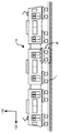
- FIG. 1 is a side view of a railway vehicle.
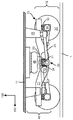
- FIG. 2 is a side view of the carriage shown by part A in FIG.
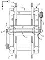
- FIG. 3 is a plan view of the carriage shown in FIG.
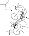
- FIG. 4 is a perspective view for explaining the operation of the traction device when the vehicle shown in FIGS. 1 to 3 accelerates.
- FIG. 5 is a perspective view for explaining the operation of the traction device when the vehicle shown in FIGS. 1 to 3 passes through a curve.
- FIG. 6 is a side view of the vehicle carriage according to the second embodiment.
- FIG. 7 is a side view of a bogie for a monorail vehicle according to a third embodiment to which the traction device shown in FIGS. 2 to 6 is applied.
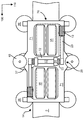
- FIG. 8 is a plan view of the bogie of the monorail vehicle shown in FIG.
- each direction is defined before the description according to the present invention.
- Each direction is a longitudinal (front-rear) direction or rail direction 100 of the rail vehicle or carriage, a width (left-right) direction or sleeper direction 110 of the rail vehicle or carriage, and a height direction 120, and is simply a longitudinal (front-rear) direction. 100, a width (left-right) direction 110, and a height (up-down) direction 120.
- a rail vehicle is a vehicle operated along a laid track, and includes a rail vehicle, a monorail vehicle, a new transportation vehicle, a tram, and the like.
- a railway vehicle and a monorail vehicle will be described as examples of rail vehicles, but the present invention can also be applied to a carriage such as a new transportation vehicle or a tram.
- FIG. 1 is a side view of a railway vehicle.
- 2 is a side view of the bogie of the vehicle shown in part A of FIG. 1
- FIG. 3 is a plan view of the bogie shown in FIG.
- the carriage 12 includes a carriage frame 70 and a wheel shaft 32 in which two wheels 31 are connected by an axle 30.
- the carriage frame 70 is composed of two side beams 71 that are spaced along the longitudinal direction 110 and a lateral beam 72 that connects the central portions of the side beams 71 in the longitudinal direction. It is a letter-shaped part. In FIG. 3, the two side beams 72 connect the side beams 71, but the side beams 71 may be connected by one side beam 72.
- the wheel shaft 32 that rolls on the rail 1 is formed by connecting two wheels 31 with an axle 30 and is held rotatably on shaft boxes 34 provided at both ends of the wheel shaft 32.
- the axle box 34 supports both ends of the side beam 71 in the longitudinal direction via an axle spring 33 provided on the upper portion thereof.
- the vehicle body 11 is connected to the carriage 12 via the vehicle body support device 40.
- the vehicle body support device 40 includes an air spring 46 that supports the load of the vehicle body in the vertical direction, and a traction device 20 that transmits the driving force or braking force of the carriage 12 (force acting in the front-rear direction 100) to the vehicle body 11. .
- the traction device 20 includes a connecting rod 21 disposed along the width direction 110 at the center of the carriage 12 in the longitudinal direction 100, and a connecting rod arm 22 having one end connected to the connecting rod 21 at both ends.
- the connecting rod arm 22 includes a tension bar 23 having one end connected to the other end, and a tension bar bracket 25 connecting the other end of the tension bar 23 and the vehicle body 11.
- the connecting rod 21 is rotatably provided at a pair of connecting rod brackets 24 whose both ends are disposed on the upper surface of the carriage frame 70 (left and right side beams 71). Between the connecting rod 21 and the connecting rod bracket 24, a bearing structure that can withstand a longitudinal force (radial load) from the carriage 12 by reducing friction and wear by a self-lubricating function such as OILES (registered trademark) is desirable.
- the connecting rod bracket 24 may be omitted, and the connecting rod 21 may be provided by forming a hole in the side surface of the side beam 71 between the two transverse beams 72 and providing the above-described bearing structure in the hole. Furthermore, when only one hollow cross beam 71 is provided, the connecting rod 21 may be provided on the center line (axis in the case of a cylinder) in the longitudinal direction (width direction 110) of the cross beam 71.
- a pair of connecting rod arms 22 provided along the height direction 120 are connected to both ends of the connecting rod 21.
- One connecting rod arm 22a (see FIG. 4) has an upper end connected to one end of the connecting rod 21 and a lower end extending downward.
- the other connecting rod arm 22b (see FIG. 4) is provided in such a manner that its lower end is connected to the other end of the connecting rod 21 and its upper end extends upward.
- the connecting rod arm 22 is provided along the height direction 120, the connecting rod arm 22 may be provided not only in the vertical direction but also in an aspect inclined in the longitudinal direction 100.
- the left and right connecting rod arms 22 have the same dimension in the height direction, and the connecting rod arm 22 and the connecting rod 21 have an integral structure connected by welding, press fitting, or the like.
- a lower end portion of one connecting rod arm 22a and a tension rod bracket 25a (see FIG. 4) provided at one end portion in the width direction 110 of the lower surface of the vehicle body 11 are connected by a tension rod 23a, and the other connecting rod arm.
- One tension bar 23a is disposed from the lower end of the connecting rod arm 22a toward one end in the longitudinal direction 100 of the vehicle, and the other tension bar 23b is disposed from the upper end of the connecting rod arm 22b in the longitudinal direction 100 of the vehicle. It is arranged toward the other end portion.
- One end of the tension bar 23 is provided with a bearing having a degree of freedom of rotation about the left-right direction 110 so that relative lateral and vertical displacement between the vehicle body and the carriage can be allowed.
- the other end may be provided with a bearing having a degree of freedom of rotation about the vertical direction 120 as an axis.
- spherical bearings that can allow displacement in the left-right direction 110 and the up-down direction 120 are provided at both ends of the tension bar 23, rubber bushes, etc.
- the elastic body may be provided.
- FIG. 4 is a perspective view for explaining the operation of the traction device when the vehicle accelerates.
- Each arrow described in the vehicle body 11, the tension rods 23a and 23b, the coupling rod arms 22a and 22b, and the coupling rod brackets 24a and 24b shown in FIG. 4 is a force acting on each component constituting the traction device when the vehicle 10 accelerates. Is shown.
- the vehicle 10 pulls the vehicle body 11 through a traction device (tensile bar) or a driving force generated by a wheel shaft 32 driven by a main motor (not shown) mounted on the carriage 12 rolling on the rail 1. Accelerate by propelling. At this time, a force A having the same magnitude and the same direction as the traction force (tensile force) is transmitted to the tension bar 23a and the propulsion force (compression force) is transmitted to the tension bar 23b.
- a traction device tensile bar
- a force A having the same magnitude and the same direction as the traction force (tensile force) is transmitted to the tension bar 23a and the propulsion force (compression force) is transmitted to the tension bar 23b.
- the moment force acts on the connecting rod 21 by the force A transmitted to the tension rods 23a and 23b and the connecting rod arms 22a and 22b.
- a moment force in the direction of arrow B acts on one end of the connecting rod 21, and a moment force in the direction of arrow C acts on the other end of the connecting rod arm 21.
- the direction of the moment force acting on one end of the connecting rod 21 is opposite (reverse) to the direction of the moment force acting on the other end of the connecting rod 21.
- the connecting rod arms 22a and 22b are integrally connected to both ends of the connecting rod 21, the moment force acting in the opposite direction on both ends of the connecting rod 21 is canceled.
- the connecting rod arms 22a and 22b are not rotationally displaced, and the force A acting on the tension rods 23a and 23b is transmitted to the vehicle body 11 as it is through the tension rod brackets 25a and 25b. Due to the balance and operation of the driving force, the vehicle 10 continues to accelerate in the forward direction.
- the carriage 12 generates a braking force
- a translation force or moment force in the opposite direction to that when the driving force is generated is generated, and the vehicle 10 decelerates.
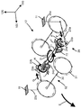
- FIG. 5 is a perspective view for explaining the operation of the traction device when the vehicle shown in FIGS. 1 to 3 passes through a curve.
- FIG. 5 shows a state in which the vehicle 10 yaws (turns) in the direction of arrow D with respect to the vehicle body 11 and passes through the left curve.
- a solid line shows the state of the vehicle body and the front carriage when passing the curve.
- the arrows on the vehicle body 11, the tension rods 23a and 23b, and the connecting rod arms 22a and 22b indicate the forces acting on the respective parts constituting the traction device when the carriage 12 yaws in the direction of arrow D with respect to the vehicle body 11. It is shown.
- An arrow E described on the front side of the carriage 12 indicates the traveling direction of the vehicle 10 passing through the left curve
- an arrow D described at the center of the carriage 12 indicates a direction in which the carriage 12 yaws the vehicle body 11.
- the connecting rod 21 is yawing-displaced (turned) in the direction of arrow D in the horizontal plane around the central portion in the longitudinal direction (width direction 110). Since the connecting rod 21 is fixed to the carriage frame 70 via the connecting rod brackets 24 a and 24 b, the carriage 12 is displaced in conjunction with the yawing movement of the connecting rod 21, and the carriage 12 is moved relative to the vehicle body 11. The yawing is displaced in the direction of arrow D as if there is a heart plate around the vertical axis in the center.
- a compressive load and a tensile load act on the connecting rod because the right angle crank moves in a horizontal plane.
- the connecting rod 21 constituting the traction device according to the present invention generates a compressive load or a tensile load in the axial direction of the connecting rod 21 when the vehicle is accelerating / decelerating and passing through a curve (when the carriage turns). In other words, only a torsional (moment) load acts on the connecting rod 21. For this reason, the weight reduction of a traction device and a trolley
- a diesel vehicle in which the propulsion shaft penetrates the central portion of the carriage in the front-rear direction
- a pendulum vehicle in which mechanisms such as a pendulum beam, a roller, and a pendulum control actuator are integrated in the central portion of the carriage, or 1
- a rail vehicle including the traction device described above can be provided.
- the connecting rod is connected to a right angle crank that rotates and rotates around the vertical axis, and has a structure that performs planar motion on the upper surface of the carriage frame (lateral beam or side beam).
- the connecting rod was disposed at a position offset in the longitudinal direction from the center of the carriage. For this reason, in order to avoid interference with parts, such as a connecting rod and a wheel, the center part of the trolley
- the connecting rod is configured to rotate about the left-right direction of the vehicle, so that the connecting rod is disposed at the center of the carriage without providing an offset in the longitudinal direction of the vehicle. it can. That is, it is possible to provide a rail vehicle including a carriage that can reduce the length of the carriage in the longitudinal direction of the carriage, which is necessary for avoiding the interference between the connecting rod and components such as wheels, and promotes the reduction in size and weight.
- the connecting rod is disposed between the horizontal beams spaced along the longitudinal direction 100 so as to be connected to the left and right side beams. You may arrange
- the connecting rod bracket may be connected to the vehicle body, and the tension rod bracket may be connected to the carriage.
- the suspension device is configured above the top surface of the carriage frame, it is possible to avoid the impact of ballast due to snowfall or the like on the traction device, so that an increase in maintenance cost of the traction device can be suppressed.
- the vehicle body and the cart, and the cart and the wheel shaft are connected by a plurality of links.
- the link is driven in conjunction with the relative yawing between the vehicle and the cart that occurs when passing the curve, and the wheel shaft is adjusted.
- the steering is performed so that the radial direction of the curve is directed, and there is no function of turning the carriage around the vertical axis at the center.
- the vehicle body and the cart are connected by a connecting rod, a tension rod, etc., and the connecting rod is rotationally displaced in conjunction with the relative yawing of the vehicle body and the cart that occurs when passing through the curve.
- FIG. 6 is a side view of the carriage of the vehicle according to the second embodiment. Parts having the same or the same effect as parts constituting the traction device shown in FIGS. 1 to 5 and the railway vehicle including the same are denoted by the same reference numerals, and only parts and structures different from FIGS. 1 to 5 will be described. .
- the two connecting rod arms 22 of the traction device 20 shown in Fig. 6 are provided at both ends of the connecting rod 21 along the height direction.
- One connecting rod arm 22a is integrally connected with the end of the connecting rod 21 by welding or the like at the central portion in the longitudinal direction, and the pulling rod 23a is connected to one end extending downward and the upper portion.
- One end portion of the yaw damper 26a is connected to the other end portion extending in the direction.
- the other end of the yaw damper 26 a is connected to a yaw damper bracket 27 a provided on the side surface of the side beam 71 that forms the carriage frame 70.
- the other connecting rod arm 22b (not shown) has an end portion of the connecting rod 21 integrally connected to the center in the longitudinal direction by welding or the like, and a tension rod 23b (shown in the drawing) at one end extending upward. None) is connected, and one end of a yaw damper 26b (not shown) is connected to the other end extending downward. The other end of the yaw damper 26 b is connected to a yaw damper bracket 27 b (not shown) provided on the side surface of the side beam 71 that forms the carriage frame 70.
- the yaw damper 26 includes a piston, a cylinder, an adjustment valve, a relief valve, and the like, and the cylinder is filled with oil.
- the connecting rod arm 22 is rotationally displaced about the left and right direction 110 together with the connecting rod 21 when a relative yawing motion occurs between the vehicle body 11 and the carriage 12 such as when the vehicle 10 passes through a curve.
- the piston of the yaw damper 26 is displaced in the extension direction with respect to the cylinder when the connecting rod arm 22 is rotated counterclockwise about the left-right direction 110, and conversely, the connecting rod arm 22 is set about the left-right direction 110. When it is rotationally displaced clockwise, it is displaced in the shortening direction with respect to the cylinder.
- a large damping force is not generated for the slow yawing motion when the vehicle 10 passes through the curve, and the vehicle 10 operates at high speed.
- a large damping force is generated for a fast yawing motion such as a snake action that occurs when traveling.
- a rotary damper or the like that attenuates the rotational motion of the connecting rod 21 is configured between the connecting rod 21 and the carriage frame 70 to attenuate the relative yawing motion of the vehicle body 11 and the carriage 12. May be.
- Example 3 is a side view of a carriage 14 of a monorail vehicle to which the traction device shown in FIGS. 2 to 6 is applied, and FIG. 8 is a plan view of the carriage 14 shown in FIG. Parts having the same or the same effect as parts constituting the traction device shown in FIGS. 1 to 6 and the railway vehicle including the same are denoted by the same reference numerals, and only parts and structures different from those in FIGS. 1 to 6 will be described. .
- the bogie frame 70 of the bogie 14 of the monorail vehicle includes three types of wheels: a running wheel 35, a guide wheel 36, and a stabilizer wheel 37.
- the traveling wheel 35 is a wheel that supports the load in the vertical direction of the vehicle body 13 and the carriage 14 of the monorail vehicle, and rolls on the upper surface of the track girder 2 having a rectangular cross section.
- the guide wheel 36 has a function of rolling the upper end portion of the side surface of the track girder 2 in a horizontal plane and guiding the monorail vehicle in the rotational direction along the track girder 2 when traveling on a curved track.
- the stabilizer wheel 37 has a function of rolling the lower end portion of the side surface of the track girder 2 in a horizontal plane and maintaining a stable posture so that the monorail vehicle does not fall on the track girder 2.
- the pulling device 20 shown in FIGS. 7 and 8 basically has a connecting rod 21 (see FIGS. 2 to 6) disposed between the horizontal beams 72 so as to penetrate the left and right side beams 71, and the upper surface of the horizontal beams 72. Are arranged.
- the main effect is that an offset arrangement in the longitudinal direction 100 of the connecting rod in the central portion of the carriage is not required with respect to the conventional virtual heart dish type traction device.
- a monorail carriage with a short axial distance can be configured.
- the axial distance can be shortened, it is possible to provide a traction device that can constitute a small and lightweight monorail carriage that can reduce the burden load on the guide wheels when passing through a curve.
- Stabilizing wheel 40 Body support device 46 Air spring 70 Bogie frame 71 Side beam 72 Side beam 73 Guide wheel support frame 74 Stabilizer wheel support frame 100 Longitudinal (longitudinal) direction 110 Left / right (width) direction 120 Up / down (high) Direction)
Landscapes
- Engineering & Computer Science (AREA)
- Mechanical Engineering (AREA)
- Platform Screen Doors And Railroad Systems (AREA)
Abstract
L'invention concerne un véhicule ferroviaire équipé d'un bogie qui peut être rendu compact et léger. Un dispositif de traction (14) pour connecter le véhicule de chemin de fer et le bogie comprend : un arbre de liaison (21) fixé à un châssis de bogie ; une paire de bras d'arbre de liaison (22) fixés aux deux extrémités de l'arbre de liaison (21) ; deux arbres de tirage (23) chacun connecté à chacun des bras d'arbre de liaison (22). Une partie d'extrémité supérieure d'un bras d'arbre de liaison (23) et l'arbre de liaison (21) sont connectés, et une partie d'extrémité inférieure de l'autre bras d'arbre de liaison (23) et l'arbre de liaison (21) sont connectés. Les bras de tirage (23) connectent chaque bras d'arbre de liaison (23) et la surface inférieure d'une caisse de véhicule. Lorsque le bogie passe par une courbe, les bras d'arbre de liaison (23) tournent dans un plan vertical. En conséquence, le bogie tourne dans un plan horizontal autour d'un axe vertical virtuel au niveau d'une partie centrale de l'arbre de liaison dans la direction longitudinale de celui-ci.
Priority Applications (2)
| Application Number | Priority Date | Filing Date | Title |
|---|---|---|---|
| PCT/JP2014/069129 WO2016009545A1 (fr) | 2014-07-18 | 2014-07-18 | Véhicule ferroviaire |
| EP14897767.1A EP3170716B1 (fr) | 2014-07-18 | 2014-07-18 | Véhicule ferroviaire |
Applications Claiming Priority (1)
| Application Number | Priority Date | Filing Date | Title |
|---|---|---|---|
| PCT/JP2014/069129 WO2016009545A1 (fr) | 2014-07-18 | 2014-07-18 | Véhicule ferroviaire |
Publications (1)
| Publication Number | Publication Date |
|---|---|
| WO2016009545A1 true WO2016009545A1 (fr) | 2016-01-21 |
Family
ID=55078062
Family Applications (1)
| Application Number | Title | Priority Date | Filing Date |
|---|---|---|---|
| PCT/JP2014/069129 Ceased WO2016009545A1 (fr) | 2014-07-18 | 2014-07-18 | Véhicule ferroviaire |
Country Status (2)
| Country | Link |
|---|---|
| EP (1) | EP3170716B1 (fr) |
| WO (1) | WO2016009545A1 (fr) |
Citations (2)
| Publication number | Priority date | Publication date | Assignee | Title |
|---|---|---|---|---|
| JPH0156941B2 (fr) * | 1983-03-10 | 1989-12-01 | Tokyo Shibaura Electric Co | |
| JP2862702B2 (ja) * | 1991-05-31 | 1999-03-03 | 株式会社東芝 | 直行・横行両用車両の台車操舵装置 |
Family Cites Families (3)
| Publication number | Priority date | Publication date | Assignee | Title |
|---|---|---|---|---|
| JPS59100051A (ja) * | 1982-11-26 | 1984-06-09 | 株式会社東芝 | 軸重移動防止装置 |
| JPH07149235A (ja) * | 1993-11-26 | 1995-06-13 | Sumitomo Metal Ind Ltd | 鉄道車両用台車のヨーダンパ装置 |
| KR101040376B1 (ko) * | 2008-12-26 | 2011-06-10 | 한국철도기술연구원 | 센터 피봇 요운동을 이용한 철도차량용 조향대차 |
-
2014
- 2014-07-18 WO PCT/JP2014/069129 patent/WO2016009545A1/fr not_active Ceased
- 2014-07-18 EP EP14897767.1A patent/EP3170716B1/fr active Active
Patent Citations (2)
| Publication number | Priority date | Publication date | Assignee | Title |
|---|---|---|---|---|
| JPH0156941B2 (fr) * | 1983-03-10 | 1989-12-01 | Tokyo Shibaura Electric Co | |
| JP2862702B2 (ja) * | 1991-05-31 | 1999-03-03 | 株式会社東芝 | 直行・横行両用車両の台車操舵装置 |
Also Published As
| Publication number | Publication date |
|---|---|
| EP3170716A1 (fr) | 2017-05-24 |
| EP3170716B1 (fr) | 2020-09-09 |
| EP3170716A4 (fr) | 2018-04-04 |
Similar Documents
| Publication | Publication Date | Title |
|---|---|---|
| JP5010630B2 (ja) | 低床式車両 | |
| US9174654B2 (en) | Drive having axle-mounted transmission for high speeds | |
| JP6034254B2 (ja) | 鉄道車両用台車 | |
| KR100657622B1 (ko) | 철도차량용 조향대차 | |
| CN110667635B (zh) | 一种轴箱内置式转向架构架 | |
| JP6004996B2 (ja) | 鉄道車両用台車 | |
| KR101772606B1 (ko) | 곡선구간 주행성능 향상을 위한 철도차량용 3축대차 구조 | |
| CN210971081U (zh) | 轨道车辆的非动力转向架系统及轨道车辆 | |
| CN102190002B (zh) | 直线电机转向架 | |
| RU2566594C2 (ru) | Тележка приводная рельсового транспортного средства, преимущественно трамвая с низким полом | |
| US8122835B2 (en) | Undercarriage for a rail vehicle | |
| JPH07172314A (ja) | 鉄道車両及び鉄道車両用台車 | |
| JP2016222237A (ja) | 鉄道車両用車体支持装置 | |
| JP2002046603A (ja) | 鉄道車両のアンチローリング装置 | |
| JP2000038132A (ja) | 鉄道車両用台車 | |
| WO2016009545A1 (fr) | Véhicule ferroviaire | |
| KR100993192B1 (ko) | 철도 차량용 윤축 조향 장치 | |
| KR101040375B1 (ko) | 3절 링크 방식을 이용한 철도차량용 조향대차 | |
| JPH0292770A (ja) | ボルスタレス台車のアンチローリング装置 | |
| JP4395914B2 (ja) | 鉄道車両用台車 | |
| CN113968255B (zh) | 转向架及轨道车辆 | |
| JPH07149235A (ja) | 鉄道車両用台車のヨーダンパ装置 | |
| KR20130046538A (ko) | 엠알 댐퍼를 사용한 철도 차량용 현가장치 | |
| JP2019137137A (ja) | 鉄道車両用台車 | |
| JP2002145061A (ja) | 鉄道車両 |
Legal Events
| Date | Code | Title | Description |
|---|---|---|---|
| 121 | Ep: the epo has been informed by wipo that ep was designated in this application |
Ref document number: 14897767 Country of ref document: EP Kind code of ref document: A1 |
|
| REEP | Request for entry into the european phase |
Ref document number: 2014897767 Country of ref document: EP |
|
| WWE | Wipo information: entry into national phase |
Ref document number: 2014897767 Country of ref document: EP |
|
| NENP | Non-entry into the national phase |
Ref country code: DE |
|
| NENP | Non-entry into the national phase |
Ref country code: JP |