WO2016013077A1 - Dispositif à cycle de réfrigération - Google Patents
Dispositif à cycle de réfrigération Download PDFInfo
- Publication number
- WO2016013077A1 WO2016013077A1 PCT/JP2014/069492 JP2014069492W WO2016013077A1 WO 2016013077 A1 WO2016013077 A1 WO 2016013077A1 JP 2014069492 W JP2014069492 W JP 2014069492W WO 2016013077 A1 WO2016013077 A1 WO 2016013077A1
- Authority
- WO
- WIPO (PCT)
- Prior art keywords
- refrigerant
- pipe
- refrigeration cycle
- cycle apparatus
- heat exchanger
- Prior art date
- Legal status (The legal status is an assumption and is not a legal conclusion. Google has not performed a legal analysis and makes no representation as to the accuracy of the status listed.)
- Ceased
Links
Images





Classifications
-
- F—MECHANICAL ENGINEERING; LIGHTING; HEATING; WEAPONS; BLASTING
- F25—REFRIGERATION OR COOLING; COMBINED HEATING AND REFRIGERATION SYSTEMS; HEAT PUMP SYSTEMS; MANUFACTURE OR STORAGE OF ICE; LIQUEFACTION SOLIDIFICATION OF GASES
- F25B—REFRIGERATION MACHINES, PLANTS OR SYSTEMS; COMBINED HEATING AND REFRIGERATION SYSTEMS; HEAT PUMP SYSTEMS
- F25B13/00—Compression machines, plants or systems, with reversible cycle
-
- F—MECHANICAL ENGINEERING; LIGHTING; HEATING; WEAPONS; BLASTING
- F25—REFRIGERATION OR COOLING; COMBINED HEATING AND REFRIGERATION SYSTEMS; HEAT PUMP SYSTEMS; MANUFACTURE OR STORAGE OF ICE; LIQUEFACTION SOLIDIFICATION OF GASES
- F25B—REFRIGERATION MACHINES, PLANTS OR SYSTEMS; COMBINED HEATING AND REFRIGERATION SYSTEMS; HEAT PUMP SYSTEMS
- F25B1/00—Compression machines, plants or systems with non-reversible cycle
-
- F—MECHANICAL ENGINEERING; LIGHTING; HEATING; WEAPONS; BLASTING
- F25—REFRIGERATION OR COOLING; COMBINED HEATING AND REFRIGERATION SYSTEMS; HEAT PUMP SYSTEMS; MANUFACTURE OR STORAGE OF ICE; LIQUEFACTION SOLIDIFICATION OF GASES
- F25B—REFRIGERATION MACHINES, PLANTS OR SYSTEMS; COMBINED HEATING AND REFRIGERATION SYSTEMS; HEAT PUMP SYSTEMS
- F25B39/00—Evaporators; Condensers
-
- F—MECHANICAL ENGINEERING; LIGHTING; HEATING; WEAPONS; BLASTING
- F25—REFRIGERATION OR COOLING; COMBINED HEATING AND REFRIGERATION SYSTEMS; HEAT PUMP SYSTEMS; MANUFACTURE OR STORAGE OF ICE; LIQUEFACTION SOLIDIFICATION OF GASES
- F25B—REFRIGERATION MACHINES, PLANTS OR SYSTEMS; COMBINED HEATING AND REFRIGERATION SYSTEMS; HEAT PUMP SYSTEMS
- F25B40/00—Subcoolers, desuperheaters or superheaters
-
- F—MECHANICAL ENGINEERING; LIGHTING; HEATING; WEAPONS; BLASTING
- F25—REFRIGERATION OR COOLING; COMBINED HEATING AND REFRIGERATION SYSTEMS; HEAT PUMP SYSTEMS; MANUFACTURE OR STORAGE OF ICE; LIQUEFACTION SOLIDIFICATION OF GASES
- F25B—REFRIGERATION MACHINES, PLANTS OR SYSTEMS; COMBINED HEATING AND REFRIGERATION SYSTEMS; HEAT PUMP SYSTEMS
- F25B41/00—Fluid-circulation arrangements
- F25B41/30—Expansion means; Dispositions thereof
- F25B41/39—Dispositions with two or more expansion means arranged in series, i.e. multi-stage expansion, on a refrigerant line leading to the same evaporator
-
- F—MECHANICAL ENGINEERING; LIGHTING; HEATING; WEAPONS; BLASTING
- F25—REFRIGERATION OR COOLING; COMBINED HEATING AND REFRIGERATION SYSTEMS; HEAT PUMP SYSTEMS; MANUFACTURE OR STORAGE OF ICE; LIQUEFACTION SOLIDIFICATION OF GASES
- F25B—REFRIGERATION MACHINES, PLANTS OR SYSTEMS; COMBINED HEATING AND REFRIGERATION SYSTEMS; HEAT PUMP SYSTEMS
- F25B2313/00—Compression machines, plants or systems with reversible cycle not otherwise provided for
- F25B2313/005—Outdoor unit expansion valves
-
- F—MECHANICAL ENGINEERING; LIGHTING; HEATING; WEAPONS; BLASTING
- F25—REFRIGERATION OR COOLING; COMBINED HEATING AND REFRIGERATION SYSTEMS; HEAT PUMP SYSTEMS; MANUFACTURE OR STORAGE OF ICE; LIQUEFACTION SOLIDIFICATION OF GASES
- F25B—REFRIGERATION MACHINES, PLANTS OR SYSTEMS; COMBINED HEATING AND REFRIGERATION SYSTEMS; HEAT PUMP SYSTEMS
- F25B2313/00—Compression machines, plants or systems with reversible cycle not otherwise provided for
- F25B2313/023—Compression machines, plants or systems with reversible cycle not otherwise provided for using multiple indoor units
- F25B2313/0233—Compression machines, plants or systems with reversible cycle not otherwise provided for using multiple indoor units in parallel arrangements
-
- F—MECHANICAL ENGINEERING; LIGHTING; HEATING; WEAPONS; BLASTING
- F25—REFRIGERATION OR COOLING; COMBINED HEATING AND REFRIGERATION SYSTEMS; HEAT PUMP SYSTEMS; MANUFACTURE OR STORAGE OF ICE; LIQUEFACTION SOLIDIFICATION OF GASES
- F25B—REFRIGERATION MACHINES, PLANTS OR SYSTEMS; COMBINED HEATING AND REFRIGERATION SYSTEMS; HEAT PUMP SYSTEMS
- F25B2313/00—Compression machines, plants or systems with reversible cycle not otherwise provided for
- F25B2313/029—Control issues
- F25B2313/0294—Control issues related to the outdoor fan, e.g. controlling speed
-
- F—MECHANICAL ENGINEERING; LIGHTING; HEATING; WEAPONS; BLASTING
- F25—REFRIGERATION OR COOLING; COMBINED HEATING AND REFRIGERATION SYSTEMS; HEAT PUMP SYSTEMS; MANUFACTURE OR STORAGE OF ICE; LIQUEFACTION SOLIDIFICATION OF GASES
- F25B—REFRIGERATION MACHINES, PLANTS OR SYSTEMS; COMBINED HEATING AND REFRIGERATION SYSTEMS; HEAT PUMP SYSTEMS
- F25B2339/00—Details of evaporators; Details of condensers
- F25B2339/04—Details of condensers
- F25B2339/047—Water-cooled condensers
-
- F—MECHANICAL ENGINEERING; LIGHTING; HEATING; WEAPONS; BLASTING
- F25—REFRIGERATION OR COOLING; COMBINED HEATING AND REFRIGERATION SYSTEMS; HEAT PUMP SYSTEMS; MANUFACTURE OR STORAGE OF ICE; LIQUEFACTION SOLIDIFICATION OF GASES
- F25B—REFRIGERATION MACHINES, PLANTS OR SYSTEMS; COMBINED HEATING AND REFRIGERATION SYSTEMS; HEAT PUMP SYSTEMS
- F25B2400/00—Component parts or details not otherwise provided for in this subclass
- F25B2400/04—Refrigeration circuit bypassing means
- F25B2400/0415—Refrigeration circuit bypassing means for receivers
-
- F—MECHANICAL ENGINEERING; LIGHTING; HEATING; WEAPONS; BLASTING
- F25—REFRIGERATION OR COOLING; COMBINED HEATING AND REFRIGERATION SYSTEMS; HEAT PUMP SYSTEMS; MANUFACTURE OR STORAGE OF ICE; LIQUEFACTION SOLIDIFICATION OF GASES
- F25B—REFRIGERATION MACHINES, PLANTS OR SYSTEMS; COMBINED HEATING AND REFRIGERATION SYSTEMS; HEAT PUMP SYSTEMS
- F25B2400/00—Component parts or details not otherwise provided for in this subclass
- F25B2400/16—Receivers
-
- F—MECHANICAL ENGINEERING; LIGHTING; HEATING; WEAPONS; BLASTING
- F25—REFRIGERATION OR COOLING; COMBINED HEATING AND REFRIGERATION SYSTEMS; HEAT PUMP SYSTEMS; MANUFACTURE OR STORAGE OF ICE; LIQUEFACTION SOLIDIFICATION OF GASES
- F25B—REFRIGERATION MACHINES, PLANTS OR SYSTEMS; COMBINED HEATING AND REFRIGERATION SYSTEMS; HEAT PUMP SYSTEMS
- F25B2600/00—Control issues
- F25B2600/11—Fan speed control
- F25B2600/112—Fan speed control of evaporator fans
-
- F—MECHANICAL ENGINEERING; LIGHTING; HEATING; WEAPONS; BLASTING
- F25—REFRIGERATION OR COOLING; COMBINED HEATING AND REFRIGERATION SYSTEMS; HEAT PUMP SYSTEMS; MANUFACTURE OR STORAGE OF ICE; LIQUEFACTION SOLIDIFICATION OF GASES
- F25B—REFRIGERATION MACHINES, PLANTS OR SYSTEMS; COMBINED HEATING AND REFRIGERATION SYSTEMS; HEAT PUMP SYSTEMS
- F25B2600/00—Control issues
- F25B2600/25—Control of valves
- F25B2600/2501—Bypass valves
-
- F—MECHANICAL ENGINEERING; LIGHTING; HEATING; WEAPONS; BLASTING
- F25—REFRIGERATION OR COOLING; COMBINED HEATING AND REFRIGERATION SYSTEMS; HEAT PUMP SYSTEMS; MANUFACTURE OR STORAGE OF ICE; LIQUEFACTION SOLIDIFICATION OF GASES
- F25B—REFRIGERATION MACHINES, PLANTS OR SYSTEMS; COMBINED HEATING AND REFRIGERATION SYSTEMS; HEAT PUMP SYSTEMS
- F25B2600/00—Control issues
- F25B2600/25—Control of valves
- F25B2600/2513—Expansion valves
-
- F—MECHANICAL ENGINEERING; LIGHTING; HEATING; WEAPONS; BLASTING
- F25—REFRIGERATION OR COOLING; COMBINED HEATING AND REFRIGERATION SYSTEMS; HEAT PUMP SYSTEMS; MANUFACTURE OR STORAGE OF ICE; LIQUEFACTION SOLIDIFICATION OF GASES
- F25B—REFRIGERATION MACHINES, PLANTS OR SYSTEMS; COMBINED HEATING AND REFRIGERATION SYSTEMS; HEAT PUMP SYSTEMS
- F25B2700/00—Sensing or detecting of parameters; Sensors therefor
- F25B2700/21—Temperatures
- F25B2700/2103—Temperatures near a heat exchanger
-
- F—MECHANICAL ENGINEERING; LIGHTING; HEATING; WEAPONS; BLASTING
- F25—REFRIGERATION OR COOLING; COMBINED HEATING AND REFRIGERATION SYSTEMS; HEAT PUMP SYSTEMS; MANUFACTURE OR STORAGE OF ICE; LIQUEFACTION SOLIDIFICATION OF GASES
- F25B—REFRIGERATION MACHINES, PLANTS OR SYSTEMS; COMBINED HEATING AND REFRIGERATION SYSTEMS; HEAT PUMP SYSTEMS
- F25B39/00—Evaporators; Condensers
- F25B39/04—Condensers
-
- Y—GENERAL TAGGING OF NEW TECHNOLOGICAL DEVELOPMENTS; GENERAL TAGGING OF CROSS-SECTIONAL TECHNOLOGIES SPANNING OVER SEVERAL SECTIONS OF THE IPC; TECHNICAL SUBJECTS COVERED BY FORMER USPC CROSS-REFERENCE ART COLLECTIONS [XRACs] AND DIGESTS
- Y02—TECHNOLOGIES OR APPLICATIONS FOR MITIGATION OR ADAPTATION AGAINST CLIMATE CHANGE
- Y02B—CLIMATE CHANGE MITIGATION TECHNOLOGIES RELATED TO BUILDINGS, e.g. HOUSING, HOUSE APPLIANCES OR RELATED END-USER APPLICATIONS
- Y02B30/00—Energy efficient heating, ventilation or air conditioning [HVAC]
- Y02B30/70—Efficient control or regulation technologies, e.g. for control of refrigerant flow, motor or heating
Definitions
- the present invention relates to a refrigeration cycle apparatus equipped with an internal heat exchanger.
- a conventional refrigeration cycle device heat is exchanged between the refrigerant on the high-pressure side and the low-pressure side, the liquid refrigerant flowing into the decompression device is supercooled, and the gas refrigerant at the outlet of the evaporator is superheated to increase the efficiency of the refrigeration cycle.
- Refrigeration cycle devices with an improved internal heat exchanger are generally known.
- the degree of supercooling at the outlet of the high-pressure side passage of the internal heat exchanger is maintained at a predetermined value, and the generation of supercooled liquid in the condenser is suppressed.
- control for increasing the heat exchange efficiency is performed (see Patent Document 1).
- the present invention has been made to solve such problems, and in a refrigeration cycle apparatus including an internal heat exchanger, excess refrigerant during supercooling operation is stored in a refrigerant container having a minimum capacity. With the goal.
- At least a compressor, a condenser, an internal heat exchanger that exchanges heat between refrigerants having different pressures, a refrigerant container that stores refrigerant, a first decompression device, and an evaporator are sequentially connected.
- a condenser and a refrigerant container are connected by a first pipe, and a second decompression device is disposed between the internal heat exchanger and the refrigerant container in the first pipe.
- the refrigerant supercooled by the internal heat exchanger is depressurized to a saturated liquid or a gas-liquid two-phase state close to the saturated liquid by the second depressurizing apparatus and flows into the refrigerant container. For this reason, surplus refrigerant can be stored to the maximum, the capacity of the refrigerant container can be reduced, and the refrigerant flowing in is not in a supercooled state, so that the gas component is slightly mixed and the refrigerant container is fully filled. Can be prevented.
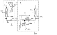
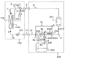
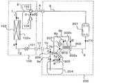
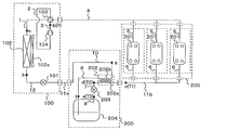
- FIG. 1 is a configuration diagram of a refrigeration cycle apparatus according to Embodiment 1.
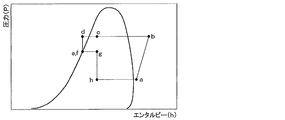
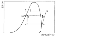
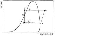
- FIG. 2 is a Mollier diagram of the refrigeration cycle apparatus according to Embodiment 1.
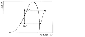
- FIG. 6 is a Mollier diagram of Modification 1 of the refrigeration cycle apparatus according to Embodiment 1.
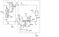
- FIG. It is a block diagram of the modification 2 of the refrigeration cycle apparatus which concerns on Embodiment 1.
- FIG. It is a block diagram of the modification 3 of the refrigeration cycle apparatus which concerns on Embodiment 1.
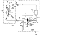
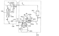
- FIG. 3 is a configuration diagram of a refrigeration cycle apparatus according to Embodiment 2.
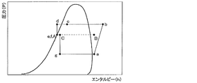
- FIG. 6 is a Mollier diagram of a refrigeration cycle apparatus according to Embodiment 2.
- FIG. 6 is a configuration diagram of Modification 1 of the refrigeration cycle apparatus according to Embodiment 2.
- FIG. 1 is a configuration diagram of a refrigeration cycle apparatus according to Embodiment 1.
- FIG. 2 is a Mollier diagram of the refrigeration cycle apparatus according to Embodiment 1.
- FIG. 6 is a Mollier
- FIG. 6 is a configuration diagram of a refrigeration cycle apparatus according to Embodiment 3.
- FIG. 6 is a Mollier diagram of a refrigeration cycle apparatus according to Embodiment 3.
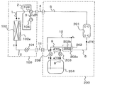
- FIG. 6 is a configuration diagram of a refrigeration cycle apparatus according to Embodiment 4.
- FIG. 6 is a Mollier diagram of a refrigeration cycle apparatus according to Embodiment 4.
- FIG. 10 It is a block diagram of the modification 1 of the refrigeration cycle apparatus which concerns on Embodiment 4.
- FIG. FIG. 10 is a Mollier diagram of Modification 1 of the refrigeration cycle apparatus according to Embodiment 4.
- 6 is a configuration diagram of a refrigeration cycle apparatus according to Embodiment 5.
- FIG. 6 is a Mollier diagram of a refrigeration cycle apparatus according to Embodiment 5.
- FIG. 10 is a configuration diagram of a refrigeration cycle apparatus according to Embodiment 6.
- FIG. 10 is a configuration diagram of a refrigeration cycle apparatus according to Embodiment 7.
- FIG. ⁇ Configuration> 1 is a configuration diagram of a refrigeration cycle apparatus according to Embodiment 1.
- FIG. FIG. 2 is a Mollier diagram of the refrigeration cycle apparatus according to Embodiment 1.
- the refrigeration cycle apparatus according to Embodiment 1 is configured by a refrigerant circuit in which an outdoor unit 100 and a heat dissipation unit 200 are connected by a gas connection pipe 4 and a liquid connection pipe 11.
- the outdoor unit 100 stores a first pressure reducing device 101, an evaporator 102, a four-way valve 103, and a compressor 104.
- the evaporator 102 provided with the air blower 102a and the four-way valve 103 are connected by the pipe 1
- the four-way valve 103 and the suction side of the compressor 104 are connected by the pipe 2, and the compressor 104
- the discharge side and the gas connection pipe 4 are connected by a pipe 3.
- the liquid connection pipe 11, the first decompression device 101, and the evaporator 102 are connected by a pipe 12.
- the heat radiating unit 200 accommodates a condenser 201 (for example, a water-refrigerant heat exchanger), an internal heat exchanger 202, a second decompression device 203, and a refrigerant container 204.
- a condenser 201 for example, a water-refrigerant heat exchanger
- the gas connection pipe 4 and the condenser 201 are connected by the pipe 5
- the condenser 201 and the high temperature side passage 202 a of the internal heat exchanger 202 are connected by the pipe 6.
- the high temperature side passage 202 a of the internal heat exchanger 202 and the second decompression device 203 are connected by a pipe 7
- the second decompression device 203 and the refrigerant container 204 are connected by a pipe 8.
- the refrigerant container 204 and the low temperature side passage 202b of the internal heat exchanger 202 are connected by the pipe 9, and the low temperature side passage 202b of the internal heat exchanger 202 and the liquid connection pipe 11 are connected by the pipe 10. Has been.
- the pressure gauge P which detects the discharge pressure of a compressor is arrange
- the thermometer T1 which detects the temperature of a refrigerant
- T2 and T3 are arranged.
- the high-pressure gas-liquid two-phase refrigerant is cooled by the medium-pressure gas-liquid two-phase refrigerant in the internal heat exchanger 202 and enters the second decompression device 203 in the state d of the supercooled liquid.
- the high-pressure supercooled liquid refrigerant is depressurized in the second decompression device 203, enters a refrigerant container 204 in a state e of a medium-pressure saturated liquid (or gas-liquid two-phase) refrigerant, and the refrigerant is a liquid single phase. In state f.
- the liquid single-phase refrigerant released from the refrigerant container 204 flows into the low temperature side passage 202b of the internal heat exchanger 202, and is discharged as the two-phase refrigerant g while cooling the high-pressure gas-liquid two-phase refrigerant.
- the two-phase refrigerant g flows into the liquid connection pipe 11 and flows into the first decompression device 101.
- the refrigerant is decompressed in the first decompression device 101, becomes a low-pressure two-phase refrigerant h, and flows into the evaporator 102.
- the refrigerant that has exchanged heat with air in the evaporator 102 to become the low-pressure vapor refrigerant a is sucked into the compressor 104 and compressed again.
- the control device (not shown) detects the temperature of the refrigerant passing through the points c, d, and e with the thermometers T1, T2, and T3, and the refrigerant at the point d reaches a predetermined excess from the measured value of the discharge pressure of the compressor 104.
- the degree of cooling for example, 5 ° C.
- the refrigerant at the point c is in a gas-liquid two-phase state
- the refrigerant at the point e is a saturated liquid or a gas-liquid two-phase refrigerant close to the saturated liquid. Control the capacity of the device.
- the degree of dryness of the outlet refrigerant of the condenser 201 is increased, and the heat is transferred into the condenser 201 by being discharged from the condenser 201 in the gas-liquid two-phase state c.
- the supercooled liquid having poor characteristics does not exist, and the heat exchange capacity of the condenser 201 is improved.
- the heat exchange capability of the condenser 201 is improved, it becomes possible to raise the upper limit temperature (for example, 55 ° C. ⁇ 60 ° C.) compared to the conventional hot water temperature.
- the condensing pressure at the time of high temperature hot water can be set low, the efficiency of the refrigeration cycle apparatus can be improved.
- the refrigerant flows into the refrigerant container 204 in a saturated liquid or a gas-liquid two-phase state close to the saturated liquid, so that surplus refrigerant can be stored as much as possible.
- the refrigerant flows into the refrigerant container 204 with some gas components mixed in, so that the refrigerant container can be prevented from becoming full.
- the refrigerant at the outlet of the high temperature side passage 202a of the internal heat exchanger 202 is in a liquid single phase and flows into the second decompression device 203, whereby the controllability of the flow rate can be improved.
- the configuration of the outdoor unit 100 can be made common to reduce the cost as a refrigeration cycle apparatus.
- FIG. 3 is a Mollier diagram of Modification 1 of the refrigeration cycle apparatus according to Embodiment 1.
- FIG. 3 the refrigerant cooled by the low-pressure gas-liquid two-phase refrigerant in the internal heat exchanger 202 and entering the second decompression device 203 in the state d of the supercooled liquid is 2
- the pressure is reduced in the pressure reducing device 203, flows out of the refrigerant container 204 as a low-pressure saturated liquid refrigerant f, and flows into the low temperature side passage 202 b of the internal heat exchanger 202.
- the refrigerant heated by the internal heat exchanger 202 enters the two-phase state g and flows into the first decompression device 101. At that time, the first pressure reducing device 101 is fully opened.
- the second decompression device 203 reduces the pressure from high pressure (state d) to low pressure (state e).
- state d high pressure
- low pressure low pressure
- the refrigerant at the outlet of the high-temperature side passage 202a of the internal heat exchanger 202 is in a liquid single phase and flows into the second decompression device 203, and the first decompression device 101 is controlled to be fully opened, thereby improving the controllability of the flow rate. Can be made.
- FIG. 4 is a configuration diagram of Modification 2 of the refrigeration cycle apparatus according to Embodiment 1.
- the air refrigerant heat exchanger 201a is employ
- FIG. 5 is a configuration diagram of Modification 3 of the refrigeration cycle apparatus according to Embodiment 1.
- the first pressure reducing device 101 is provided on the pipe 10 in the heat dissipation unit 200.
- FIG. ⁇ Configuration> FIG. 6 is a configuration diagram of the refrigeration cycle apparatus according to the second embodiment.
- FIG. 7 is a Mollier diagram of the refrigeration cycle apparatus according to the second embodiment.
- the refrigeration cycle apparatus according to Embodiment 2 is configured by a refrigerant circuit in which an outdoor unit 100 and a heat dissipation unit 200 are connected by a gas connection pipe 4 and a liquid connection pipe 11 as shown in FIG.
- the outdoor unit 100 stores a first pressure reducing device 101, an evaporator 102, a four-way valve 103, and a compressor 104.
- the evaporator 102 provided with the air blower 102a and the four-way valve 103 are connected by the pipe 1
- the four-way valve 103 and the suction side of the compressor 104 are connected by the pipe 2, and the compressor 104
- the discharge side and the gas connection pipe 4 are connected by a pipe 3.
- the liquid connection pipe 11, the first decompression device 101, and the evaporator 102 are connected by a pipe 12.
- the heat radiating unit 200 accommodates a condenser 201 (for example, a water-refrigerant heat exchanger), an internal heat exchanger 202, a second decompression device 203, and a refrigerant container 204.
- a condenser 201 for example, a water-refrigerant heat exchanger
- an internal heat exchanger 202 for example, a water-refrigerant heat exchanger
- a second decompression device 203 for example, a refrigerant container 204.
- refrigerant container 204 for example, a condenser 201 (for example, a water-refrigerant heat exchanger), an internal heat exchanger 202, a second decompression device 203, and a refrigerant container 204.
- the gas connection pipe 4 and the condenser 201 are connected by the pipe 5
- the condenser 201 and the high temperature side passage 202 a of the internal heat exchanger 202 are connected by the pipe
- the high-temperature side passage 202a of the internal heat exchanger 202 and the second decompression device 203 are connected by the pipe 7, the second decompression device 203 and the branch portion 205 are connected by the pipe 8, and the branch portion 205 and the refrigerant container 204 are connected. It is connected by a pipe 8a.
- merging part 206 are connected by the piping 9a, and the branch part 205 and the low temperature side channel
- the low-temperature side passage 202b of the internal heat exchanger 202 and the junction 206 are connected by a pipe 9b, and the junction 206 and the liquid connection pipe 11 are connected by a pipe 10.
- the pressure gauge P which detects the discharge pressure of a compressor is arrange
- the thermometer T1 which detects the temperature of a refrigerant
- T2 and T3 are arranged.
- the high-pressure gas-liquid two-phase refrigerant is cooled by the medium-pressure gas-liquid two-phase refrigerant in the internal heat exchanger 202 and enters the second decompression device 203 in the state d of the supercooled liquid.
- the high-pressure supercooled liquid refrigerant is decompressed by the second decompression device 203 and flows into the branching section 205 in a state e of a medium-pressure saturated liquid (or gas-liquid two-phase) refrigerant.
- the refrigerant branched at the branching portion 205 flows into the refrigerant container 204 and the low temperature side passage 202b of the internal heat exchanger 202.
- the refrigerant flowing into the refrigerant container 204 flows out in the liquid single-phase state f.
- the refrigerant that has flowed into the internal heat exchanger 202 as the state A flows into the state B while cooling the high-pressure gas-liquid two-phase refrigerant.
- the refrigerants that have flowed out of the refrigerant container 204 and the internal heat exchanger 202 are joined together at the joining unit 206.
- the refrigerant merged at the merge unit 206 enters a state C and flows into the liquid connection pipe 11 and flows into the first pressure reducing device 101.
- the refrigerant in the state C is depressurized in the first decompression device 101, enters the state g, and flows into the evaporator 102. Heat is exchanged with air in the evaporator 102 to form a low-pressure vapor refrigerant a, which is sucked into the compressor 104 and compressed again.
- the control device (not shown) detects the temperature of the refrigerant passing through the points c, d, and e with the thermometers T1, T2, and T3, and the refrigerant at the point d reaches a predetermined excess from the measured value of the discharge pressure of the compressor 104.
- Each pressure reducing device or blower is set to a degree of cooling (for example, 5 ° C.)
- the refrigerant at point c is in a gas-liquid two-phase state
- the refrigerant at point e is a saturated liquid or a two-phase refrigerant close to a saturated liquid. Control the capacity.
- the refrigerant flows into the refrigerant container 204 in a saturated liquid or a gas-liquid two-phase state close to the saturated liquid, so that surplus refrigerant can be stored as much as possible.
- the refrigerant flows into the refrigerant container 204 with some gas components mixed in, so that the refrigerant container can be prevented from becoming full.
- the refrigerant at the outlet of the high temperature side passage 202a of the internal heat exchanger 202 is in a liquid single phase and flows into the second decompression device 203, whereby the controllability of the flow rate can be improved.
- the configuration of the outdoor unit 100 can be made common to reduce the cost as a refrigeration cycle apparatus.
- the amount of heat exchange in the internal heat exchanger can be increased by setting the inlet of the low temperature side passage 202b of the internal heat exchanger 202 to a two-phase state. Further, by diverting the refrigerant at the branching portion 205, the amount of refrigerant in the low temperature side passage 202b of the internal heat exchanger 202 is reduced, and the internal heat exchanger 202 can be downsized.
- FIG. 8 is a configuration diagram of Modification 1 of the refrigeration cycle apparatus according to Embodiment 2.
- the third embodiment is that the third pressure reducing device 207 is arranged in the pipe 8b between the branching portion 205 and the low temperature side passage 202b of the internal heat exchanger 202. Is different.
- the refrigerant flow rate in the low temperature side passage 202b of the internal heat exchanger 202 can be controlled by the third decompression device 207, so that the high temperature side passage 202a of the internal heat exchanger 202 can be controlled. It becomes possible to finely control the degree of supercooling of the outlet refrigerant.
- FIG. 9 is a configuration diagram of a refrigeration cycle apparatus according to Embodiment 3.
- FIG. 10 is a Mollier diagram of the refrigeration cycle apparatus according to Embodiment 3.
- the refrigeration cycle apparatus according to Embodiment 3 includes a refrigerant circuit in which an outdoor unit 100 and a heat dissipation unit 200 are connected by a gas connection pipe 4 and a liquid connection pipe 11.
- the outdoor unit 100 stores a first pressure reducing device 101, an evaporator 102, a four-way valve 103, and a compressor 104.
- the evaporator 102 provided with the air blower 102a and the four-way valve 103 are connected by the pipe 1
- the four-way valve 103 and the suction side of the compressor 104 are connected by the pipe 2, and the compressor 104
- the discharge side and the gas connection pipe 4 are connected by a pipe 3.
- the liquid connection pipe 11, the first decompression device 101, and the evaporator 102 are connected by a pipe 12.
- the heat radiating unit 200 accommodates a condenser 201 (for example, a water-refrigerant heat exchanger), an internal heat exchanger 202, a second decompression device 203, and a refrigerant container 204.
- a condenser 201 for example, a water-refrigerant heat exchanger
- the gas connection pipe 4 and the condenser 201 are connected by the pipe 5
- the condenser 201 and the high temperature side passage 202 a of the internal heat exchanger 202 are connected by the pipe 6.
- the high temperature side passage 202 a of the internal heat exchanger 202 and the second decompression device 203 are connected by a pipe 7
- the second decompression device 203 and the refrigerant container 204 are connected by a pipe 8.
- the refrigerant container 204 and the low temperature side passage 202 b of the internal heat exchanger 202 are connected by a pipe 9, and a fourth decompression device 208 is installed in the pipe 9.
- the low-temperature side passage 202b of the internal heat exchanger 202 and the liquid connection pipe 11 are connected by the pipe 10.
- the pressure gauge P which detects the discharge pressure of a compressor is arrange
- the thermometer T1 which detects the temperature of a refrigerant
- T2 and T3 are arranged.
- the high-pressure gas-liquid two-phase refrigerant is cooled by the medium-pressure gas-liquid two-phase refrigerant in the internal heat exchanger 202 and enters the second decompression device 203 in the state d of the supercooled liquid.
- the high-pressure supercooled liquid refrigerant is depressurized in the second decompression device 203, enters a refrigerant container 204 in a state e of a medium-pressure saturated liquid (or gas-liquid two-phase) refrigerant, and the refrigerant is a liquid single phase. In state f.
- the low-pressure two-phase refrigerant h passes through the liquid connection pipe 11 and flows into the first decompression device 101.
- the first decompression device 101 is controlled to be fully opened, and the refrigerant flows out from the first decompression device 101 in the state i and flows into the evaporator 102.
- the refrigerant that has exchanged heat with air in the evaporator 102 to become the low-pressure vapor refrigerant a is sucked into the compressor 104 and compressed again.
- the control device (not shown) detects the temperature of the refrigerant passing through the points c, d, and e with the thermometers T1, T2, and T3, and the refrigerant at the point d reaches a predetermined excess from the measured value of the discharge pressure of the compressor 104.
- Each pressure reducing device or blower is set to a degree of cooling (for example, 5 ° C.)
- the refrigerant at point c is in a gas-liquid two-phase state
- the refrigerant at point e is a saturated liquid or a two-phase refrigerant close to a saturated liquid. Control the capacity.
- the refrigerant flows into the refrigerant container 204 in a saturated liquid or a gas-liquid two-phase state close to the saturated liquid, so that surplus refrigerant can be stored as much as possible.
- the refrigerant flows into the refrigerant container 204 with some gas components mixed in, so that the refrigerant container can be prevented from becoming full.
- the refrigerant at the outlet of the high temperature side passage 202a of the internal heat exchanger 202 is in a liquid single phase and flows into the second decompression device 203 and the fourth decompression device 208, so that the controllability of the flow rate can be improved.
- the configuration of the outdoor unit 100 can be made common to reduce the cost as a refrigeration cycle apparatus.
- the refrigerant decompressed from the high pressure (state d) to the low pressure (state g) by the fourth decompression device 208 exchanges heat in the internal heat exchanger 202.
- the difference between high and low pressure becomes large, and the heat exchange amount can be increased.
- the controllability of the flow rate can be improved by controlling the refrigerant f at the outlet of the refrigerant container 204 to be in a liquid single phase and flowing into the fourth decompression device 208 and fully opening the first decompression device 101.
- FIG. 11 is a configuration diagram of a refrigeration cycle apparatus according to Embodiment 4.
- FIG. 12 is a Mollier diagram of the refrigeration cycle apparatus according to Embodiment 4.
- the refrigeration cycle apparatus according to Embodiment 4 includes a refrigerant circuit in which an outdoor unit 100 and a heat dissipation unit 200 are connected by a gas connection pipe 4 and a liquid connection pipe 11.
- the outdoor unit 100 stores a first pressure reducing device 101, an evaporator 102, a four-way valve 103, and a compressor 104.
- the evaporator 102 provided with the air blower 102a and the four-way valve 103 are connected by the pipe 1
- the four-way valve 103 and the suction side of the compressor 104 are connected by the pipe 2, and the compressor 104
- the discharge side and the gas connection pipe 4 are connected by a pipe 3.
- the liquid connection pipe 11, the first decompression device 101, and the evaporator 102 are connected by a pipe 12.
- the heat radiating unit 200 accommodates a condenser 201 (for example, a water-refrigerant heat exchanger), an internal heat exchanger 202, a second decompression device 203, and a refrigerant container 204.
- a condenser 201 for example, a water-refrigerant heat exchanger
- an internal heat exchanger 202 for example, a water-refrigerant heat exchanger
- a second decompression device 203 for example, a refrigerant container 204.
- the gas connection pipe 4 and the condenser 201 are connected by the pipe 5
- the condenser 201 and the high temperature side passage 202 a of the internal heat exchanger 202 are connected by the pipe 6, and the internal heat exchanger 202
- the high temperature side passage 202 a and the branching portion 205 are connected by the pipe 7.
- branch portion 205 and the second decompression device 203 are connected by a pipe 7a
- the second decompression device 203 and the refrigerant container 204 are connected by a pipe 8a
- the refrigerant container 204 and the junction portion 206 are connected by a pipe 9a.
- the branching portion 205 and the third decompression device 207 (closed during normal operation) are connected by a pipe 7b.
- the third decompression device 207 and the low temperature side passage 202b of the internal heat exchanger 202 are connected by the pipe 8b
- the low temperature side passage 202b of the internal heat exchanger 202 and the merging portion 206 are connected by the pipe 9b.
- the liquid connection pipe 11 are connected by the pipe 10.
- the pressure gauge P which detects the discharge pressure of a compressor is arrange
- the thermometer T1 which detects the temperature of a refrigerant
- T2 and T3 are arranged.
- the high-pressure supercooled liquid refrigerant is depressurized by the second decompression device 203, enters the refrigerant container 204 in the state e of the medium-pressure liquid refrigerant, and the refrigerant flows out in the liquid single-phase state f. Flow into.
- the refrigerant flowing into the third decompression device 207 flows out as the state A of the medium pressure gas-liquid two-phase refrigerant.
- the medium-pressure gas-liquid two-phase refrigerant flows into the internal heat exchanger 202, enters state B while cooling the high-pressure gas-liquid two-phase refrigerant from the condenser 201, and flows into the junction 206.
- the superheated refrigerant B enters the state C of the medium-pressure gas-liquid two-phase refrigerant at the junction 206 and flows into the first decompression device 101 through the liquid connection pipe 11.
- This refrigerant is decompressed by the first decompression device 101, becomes a low-pressure gas-liquid two-phase refrigerant state g, and flows into the evaporator 102.
- the low-pressure vapor refrigerant a that has exchanged heat with air in the evaporator 102 is sucked into the compressor 104 and compressed again.
- the control device (not shown) detects the temperature of the refrigerant passing through the points c, d, and e with the thermometers T1, T2, and T3, and the refrigerant at the point d reaches a predetermined excess from the measured value of the discharge pressure of the compressor 104.
- Each pressure reducing device or blower is set to a degree of cooling (for example, 5 ° C.)
- the refrigerant at point c is in a gas-liquid two-phase state
- the refrigerant at point e is a saturated liquid or a two-phase refrigerant close to a saturated liquid. Control the capacity.
- the second pressure reducing device 203 changes to a state e of a medium-pressure gas-liquid two-phase refrigerant and flows into the refrigerant container 204.
- the refrigerant flows out in a liquid single-phase state f, passes through the liquid connection pipe 11, and passes through the first pressure reducing device 101. Flow into.
- This liquid refrigerant is decompressed in the first decompression device 101, enters a state g, and flows into the evaporator 102.
- the low-pressure vapor refrigerant a that exchanges heat with air in the evaporator 102 is sucked into the compressor 104 and compressed again.
- the refrigerant flows into the refrigerant container 204 in a saturated liquid or a gas-liquid two-phase state close to the saturated liquid, so that surplus refrigerant can be stored as much as possible.
- the refrigerant flows into the refrigerant container 204 with some gas components mixed in, so that the refrigerant container can be prevented from becoming full.
- the refrigerant at the outlet of the high temperature side passage 202a of the internal heat exchanger 202 is in a liquid single phase and flows into the second decompression device 203 and the third decompression device 207, so that the controllability of the flow rate can be improved.
- the configuration of the outdoor unit 100 can be made common to reduce the cost as a refrigeration cycle apparatus.
- the third decompression device 207 can control the refrigerant flow rate in the low-temperature side passage 202b of the internal heat exchanger 202, so that the degree of supercooling at the point d can be finely controlled. Further, during normal operation, the amount of heat exchange of the condenser 201 can be improved by controlling the degree of supercooling at the outlet of the condenser 201 based on the temperature and pressure at the outlet of the condenser 201.
- FIG. 13 is a configuration diagram of Modification 1 of the refrigeration cycle apparatus according to Embodiment 4.
- FIG. 14 is a Mollier diagram of Modification 1 of the refrigeration cycle apparatus according to Embodiment 4.
- the modification 1 is different from the fourth embodiment in that the joining portion 206 of the pipe 9b is disposed on the downstream side of the second decompression device 203 as shown in FIG. That is, the second decompression device 203 and the merging portion 206 are connected by the pipe 8a, the merging portion 206 and the refrigerant container 204 are connected by the pipe 8c, and the refrigerant container 204, the liquid connection pipe 11 and the pipe 10 are connected. .
- the refrigerant at the outlet of the refrigerant container 204 becomes the liquid single phase f and flows into the first decompression device 101, so that the flow rate control performance can be prevented from being lowered.
- FIG. 15 is a configuration diagram of the refrigeration cycle apparatus according to the fifth embodiment.
- FIG. 16 is a Mollier diagram of the refrigeration cycle apparatus according to Embodiment 5.
- the refrigeration cycle apparatus according to Embodiment 5 is configured by a refrigerant circuit in which an outdoor unit 100 and a heat dissipation unit 200 are connected by a gas connection pipe 4 and a liquid connection pipe 11 as shown in FIG.
- the fourth decompression device 208 is arranged in the pipe 9a of the heat dissipation unit 200 of the refrigeration cycle apparatus according to Embodiment 4.
- the high-pressure vapor refrigerant b compressed by the compressor 104 is condensed by the condenser 201 and enters a state c of a high-pressure gas-liquid two-phase refrigerant and flows into the internal heat exchanger 202.
- the high-pressure gas-liquid two-phase refrigerant is cooled by the medium-pressure gas-liquid two-phase refrigerant in the internal heat exchanger 202, and enters the branching portion 205 in a supercooled liquid state d.
- the refrigerant flows from the branching unit 205 into the second decompression device 203 and the third decompression device 207.
- the high-pressure supercooled liquid refrigerant is depressurized in the second decompression device 203, enters the refrigerant container 204 in the state e of the medium-pressure liquid refrigerant, and flows out in the state f of the medium-pressure liquid refrigerant.
- the medium-pressure liquid refrigerant flows into the fourth decompression device 208 and is decompressed to become a low-pressure gas-liquid two-phase refrigerant state g and flows into the junction 206.
- the refrigerant flowing into the third decompression device 207 is decompressed and flows out as the state A of the low-pressure gas-liquid two-phase refrigerant.
- the low-pressure gas-liquid two-phase refrigerant flows into the internal heat exchanger 202 and exchanges heat while cooling the high-pressure gas-liquid two-phase refrigerant from the condenser 201.
- the refrigerant in the state B that has flowed out of the internal heat exchanger 202 flows into the junction 206.
- the refrigerant in the state B enters the state C of the low-pressure gas-liquid two-phase refrigerant at the junction 206 and flows into the first decompression device 101 through the liquid connection pipe 11.
- the first decompression device 101 is controlled to be fully opened, and the refrigerant flows out from the first decompression device 101 in the state h and flows into the evaporator 102. Heat is exchanged with air in the evaporator 102 to form a low-pressure vapor refrigerant a, which is sucked into the compressor 104 and compressed again.
- the control device (not shown) detects the temperature of the refrigerant passing through the points c, d, and e with the thermometers T1, T2, and T3, and the refrigerant at the point d reaches a predetermined excess from the measured value of the discharge pressure of the compressor 104.
- Each pressure reducing device or blower is set to a degree of cooling (for example, 5 ° C.)
- the refrigerant at point c is in a gas-liquid two-phase state
- the refrigerant at point e is a saturated liquid or a two-phase refrigerant close to a saturated liquid. Control the capacity.
- the second pressure reducing device 203 enters the state e of the medium-pressure gas-liquid two-phase refrigerant, flows into the refrigerant container 204, flows out in the liquid single-phase state f, and flows into the first pressure reducing device 101.
- the liquid refrigerant is depressurized in the first decompression device 101, enters a state h, and flows into the evaporator 102. Heat is exchanged with air in the evaporator 102 to form a low-pressure vapor refrigerant a, which is sucked into the compressor 104 and compressed again.
- the refrigerant flows into the refrigerant container 204 in a saturated liquid or a gas-liquid two-phase state close to the saturated liquid, so that surplus refrigerant can be stored as much as possible.
- the refrigerant flows into the refrigerant container 204 with some gas components mixed in, so that the refrigerant container can be prevented from becoming full.
- the refrigerant at the outlet of the high temperature side passage 202a of the internal heat exchanger 202 is in a liquid single phase and flows into the second decompression device 203 and the third decompression device 207, so that the controllability of the flow rate can be improved.
- the configuration of the outdoor unit 100 can be made common to reduce the cost as a refrigeration cycle apparatus.
- the fourth pressure reducing device 208 allows the internal heat exchanger 202 to exchange heat between the low-pressure and high-pressure refrigerant, thereby improving the amount of heat exchange.
- FIG. 17 is a configuration diagram of a refrigeration cycle apparatus according to Embodiment 6.
- the outdoor unit 100, the high-pressure rise suppression unit 300, and the heat dissipation unit 200 include the gas connection pipe 4, the first liquid connection pipe 11a, and the second liquid connection pipe 11b. Connected with.
- the outdoor unit 100 stores a first pressure reducing device 101, an evaporator 102, a four-way valve 103, and a compressor 104.
- the heat radiation unit 200 contains a condenser 201 (for example, a water-refrigerant heat exchanger).
- a condenser 201 for example, a water-refrigerant heat exchanger.
- an internal heat exchanger 202, a second decompression device 203, and a refrigerant container 204 are accommodated.
- the connection structure of each piping is the same as that of Embodiment 1.
- the high-pressure rise suppression unit 300 is arranged independently, so the configurations of the outdoor unit 100 and the heat dissipation unit 200 are shared, and the condenser 201 The high pressure rise can be suppressed. Further, by sharing the configuration of the outdoor unit 100 and the heat radiating unit 200, the cost can be reduced.
- FIG. 18 is a configuration diagram of a refrigeration cycle apparatus according to Embodiment 7.
- the refrigeration cycle apparatus according to Embodiment 7 includes an outdoor unit 100, a high-pressure rise suppression unit 300, and a plurality of heat radiation units 200 connected in parallel to the outdoor unit 100.
- the gas connection pipe 4, the first liquid connection pipe 11a and the second liquid connection pipe 11b are connected.
- the connection structure of each piping is the same as that of Embodiment 1.
- Embodiment 7 The operation of the refrigeration cycle apparatus according to Embodiment 7 is the same as that of Embodiment 1.
- ⁇ Effect> The refrigeration cycle apparatus according to the seventh embodiment suppresses the high pressure rise of the condensers 201 of the plurality of heat radiation units 200 with one outdoor unit 100 and the high pressure rise suppression unit 300 in addition to the effect according to the first embodiment. It becomes possible.
Landscapes
- Engineering & Computer Science (AREA)
- Physics & Mathematics (AREA)
- Mechanical Engineering (AREA)
- Thermal Sciences (AREA)
- General Engineering & Computer Science (AREA)
- Compression-Type Refrigeration Machines With Reversible Cycles (AREA)
- Other Air-Conditioning Systems (AREA)
- Devices That Are Associated With Refrigeration Equipment (AREA)
Abstract
Priority Applications (5)
| Application Number | Priority Date | Filing Date | Title |
|---|---|---|---|
| US15/313,625 US10508835B2 (en) | 2014-07-23 | 2014-07-23 | Refrigeration cycle apparatus |
| JP2016535581A JP6223574B2 (ja) | 2014-07-23 | 2014-07-23 | 冷凍サイクル装置 |
| CN201480079222.5A CN106461275B (zh) | 2014-07-23 | 2014-07-23 | 制冷循环装置 |
| PCT/JP2014/069492 WO2016013077A1 (fr) | 2014-07-23 | 2014-07-23 | Dispositif à cycle de réfrigération |
| GB1619972.1A GB2543669B (en) | 2014-07-23 | 2014-07-23 | Refrigeration cycle apparatus |
Applications Claiming Priority (1)
| Application Number | Priority Date | Filing Date | Title |
|---|---|---|---|
| PCT/JP2014/069492 WO2016013077A1 (fr) | 2014-07-23 | 2014-07-23 | Dispositif à cycle de réfrigération |
Publications (1)
| Publication Number | Publication Date |
|---|---|
| WO2016013077A1 true WO2016013077A1 (fr) | 2016-01-28 |
Family
ID=55162633
Family Applications (1)
| Application Number | Title | Priority Date | Filing Date |
|---|---|---|---|
| PCT/JP2014/069492 Ceased WO2016013077A1 (fr) | 2014-07-23 | 2014-07-23 | Dispositif à cycle de réfrigération |
Country Status (5)
| Country | Link |
|---|---|
| US (1) | US10508835B2 (fr) |
| JP (1) | JP6223574B2 (fr) |
| CN (1) | CN106461275B (fr) |
| GB (1) | GB2543669B (fr) |
| WO (1) | WO2016013077A1 (fr) |
Cited By (3)
| Publication number | Priority date | Publication date | Assignee | Title |
|---|---|---|---|---|
| JP2021050841A (ja) * | 2019-09-24 | 2021-04-01 | 株式会社マック | 冷凍方法 |
| JPWO2022162775A1 (fr) * | 2021-01-27 | 2022-08-04 | ||
| US11486617B2 (en) | 2017-10-27 | 2022-11-01 | Mitsubishi Electric Corporation | Refrigeration cycle apparatus |
Families Citing this family (3)
| Publication number | Priority date | Publication date | Assignee | Title |
|---|---|---|---|---|
| JP6180652B2 (ja) * | 2014-10-16 | 2017-08-16 | 三菱電機株式会社 | 冷凍サイクル装置及び液面検出センサ |
| JP7303413B2 (ja) | 2018-09-28 | 2023-07-05 | ダイキン工業株式会社 | ヒートポンプ装置 |
| DE112021007431T5 (de) * | 2021-03-31 | 2024-02-15 | Mitsubishi Electric Corporation | Kühlkreislauf-vorrichtung |
Citations (2)
| Publication number | Priority date | Publication date | Assignee | Title |
|---|---|---|---|---|
| JPH0545007A (ja) * | 1991-08-09 | 1993-02-23 | Nippondenso Co Ltd | 冷凍サイクル |
| JP2008096095A (ja) * | 2006-09-13 | 2008-04-24 | Daikin Ind Ltd | 冷凍装置 |
Family Cites Families (43)
| Publication number | Priority date | Publication date | Assignee | Title |
|---|---|---|---|---|
| JPS5372253U (fr) * | 1976-11-19 | 1978-06-16 | ||
| US4179894A (en) * | 1977-12-28 | 1979-12-25 | Wylain, Inc. | Dual source heat pump |
| US4286435A (en) * | 1978-10-02 | 1981-09-01 | Carrier Corporation | Hot gas defrost system |
| US4236381A (en) * | 1979-02-23 | 1980-12-02 | Intertherm Inc. | Suction-liquid heat exchanger having accumulator and receiver |
| US4308042A (en) * | 1980-04-11 | 1981-12-29 | Atlantic Richfield Company | Heat pump with freeze-up prevention |
| JPH0968371A (ja) * | 1995-08-31 | 1997-03-11 | Nippon Soken Inc | 気液分離器 |
| FR2779216B1 (fr) * | 1998-05-28 | 2000-08-04 | Valeo Climatisation | Dispositif de climatisation de vehicule utilisant un fluide refrigerant a l'etat supercritique |
| JP3801006B2 (ja) | 2001-06-11 | 2006-07-26 | ダイキン工業株式会社 | 冷媒回路 |
| JP2005337592A (ja) * | 2004-05-27 | 2005-12-08 | Tgk Co Ltd | 冷凍サイクル |
| JP4841288B2 (ja) * | 2006-03-29 | 2011-12-21 | 三洋電機株式会社 | 冷凍装置 |
| JP2008057807A (ja) * | 2006-08-29 | 2008-03-13 | Samsung Electronics Co Ltd | 冷凍サイクル及びそれを用いた空気調和機、冷蔵庫 |
| JP5145674B2 (ja) * | 2006-09-11 | 2013-02-20 | ダイキン工業株式会社 | 冷凍装置 |
| JP2008098095A (ja) | 2006-10-16 | 2008-04-24 | Olympus Corp | 光源装置 |
| JP5197576B2 (ja) | 2007-03-27 | 2013-05-15 | 三菱電機株式会社 | ヒートポンプ装置 |
| JP5136165B2 (ja) | 2007-06-29 | 2013-02-06 | ダイキン工業株式会社 | 冷凍装置 |
| JP5042058B2 (ja) * | 2008-02-07 | 2012-10-03 | 三菱電機株式会社 | ヒートポンプ式給湯用室外機及びヒートポンプ式給湯装置 |
| US20100186440A1 (en) * | 2009-01-27 | 2010-07-29 | Denso International America, Inc. | Thermal storage for co2 system |
| JP5452138B2 (ja) | 2009-09-01 | 2014-03-26 | 三菱電機株式会社 | 冷凍空調装置 |
| JP2011094871A (ja) * | 2009-10-29 | 2011-05-12 | Mitsubishi Electric Corp | 冷凍・空調装置、冷凍・空調装置の設置方法 |
| US9909786B2 (en) * | 2010-03-08 | 2018-03-06 | Carrier Corporation | Refrigerant distribution apparatus and methods for transport refrigeration system |
| US9453668B2 (en) * | 2010-10-18 | 2016-09-27 | Mitsubishi Electric Corporation | Refrigeration cycle apparatus and refrigerant circulating method |
| JP5851771B2 (ja) * | 2011-08-31 | 2016-02-03 | 三菱重工業株式会社 | 超臨界サイクルおよびそれを用いたヒートポンプ給湯機 |
| CN103175323B (zh) * | 2011-12-23 | 2017-03-01 | 东普雷股份有限公司 | 使用三重管式热交换器的制冷装置 |
| GB2510547B (en) * | 2012-03-01 | 2016-04-27 | Waste Heat Recovery Ltd | Heat recovery |
| JP5531045B2 (ja) * | 2012-03-16 | 2014-06-25 | 株式会社日本自動車部品総合研究所 | 冷却装置 |
| WO2014054178A1 (fr) * | 2012-10-05 | 2014-04-10 | 三菱電機株式会社 | Dispositif de pompe à chaleur |
| JP5579243B2 (ja) * | 2012-10-26 | 2014-08-27 | 三菱電機株式会社 | 冷凍サイクル装置 |
| US9188376B2 (en) * | 2012-12-20 | 2015-11-17 | Mitsubishi Electric Corporation | Refrigerant charge assisting device, air-conditioning apparatus, and refrigerant charge assisting program |
| EP2962043B1 (fr) * | 2013-03-01 | 2018-06-27 | 7AC Technologies, Inc. | Système de conditionnement d'air déshydratant |
| JP6299495B2 (ja) * | 2013-08-29 | 2018-03-28 | 株式会社デンソー | エジェクタ式冷凍サイクル |
| JP5999050B2 (ja) * | 2013-08-29 | 2016-09-28 | 株式会社デンソー | エジェクタ式冷凍サイクルおよびエジェクタ |
| JP6017058B2 (ja) * | 2013-10-24 | 2016-10-26 | 三菱電機株式会社 | 空気調和装置 |
| DE102014202849A1 (de) * | 2014-02-17 | 2015-08-20 | Siemens Aktiengesellschaft | Verfahren und Vorrichtung zum Beladen eines thermischen Schichtspeichers |
| JP6164427B2 (ja) * | 2014-03-28 | 2017-07-19 | 株式会社富士通ゼネラル | ロータリ圧縮機 |
| JP2016003828A (ja) * | 2014-06-18 | 2016-01-12 | 株式会社デンソー | 冷凍サイクル装置 |
| JP6432339B2 (ja) * | 2014-12-25 | 2018-12-05 | 株式会社デンソー | 冷凍サイクル装置 |
| WO2016103584A1 (fr) * | 2014-12-26 | 2016-06-30 | ダイキン工業株式会社 | Climatiseur de type à accumulation de chaleur |
| WO2017103939A1 (fr) * | 2015-12-18 | 2017-06-22 | Bry-Air [Asia] Pvt. Ltd. | Dispositifs à cycle hybride de compression-adsorption de vapeur et leur procédé de mise en œuvre |
| JP6569536B2 (ja) * | 2016-01-08 | 2019-09-04 | 株式会社富士通ゼネラル | 空気調和装置 |
| EP3404340B1 (fr) * | 2016-01-14 | 2021-10-06 | Mitsubishi Electric Corporation | Dispositif à cycle frigorifique |
| JPWO2017145826A1 (ja) * | 2016-02-24 | 2018-12-13 | Agc株式会社 | 冷凍サイクル装置 |
| WO2017160346A1 (fr) * | 2016-03-16 | 2017-09-21 | Inertech Ip Llc | Système et procédés utilisant des dispositifs refroidisseurs à fluide et des dispositifs réfrigérants pour effectuer un rejet de chaleur et un refroidissement auxiliaire en série |
| US11466909B2 (en) * | 2016-08-17 | 2022-10-11 | Marc-André LESMERISES | Refrigeration system and method for operating same |
-
2014
- 2014-07-23 US US15/313,625 patent/US10508835B2/en active Active
- 2014-07-23 JP JP2016535581A patent/JP6223574B2/ja not_active Expired - Fee Related
- 2014-07-23 GB GB1619972.1A patent/GB2543669B/en not_active Expired - Fee Related
- 2014-07-23 CN CN201480079222.5A patent/CN106461275B/zh not_active Expired - Fee Related
- 2014-07-23 WO PCT/JP2014/069492 patent/WO2016013077A1/fr not_active Ceased
Patent Citations (2)
| Publication number | Priority date | Publication date | Assignee | Title |
|---|---|---|---|---|
| JPH0545007A (ja) * | 1991-08-09 | 1993-02-23 | Nippondenso Co Ltd | 冷凍サイクル |
| JP2008096095A (ja) * | 2006-09-13 | 2008-04-24 | Daikin Ind Ltd | 冷凍装置 |
Cited By (5)
| Publication number | Priority date | Publication date | Assignee | Title |
|---|---|---|---|---|
| US11486617B2 (en) | 2017-10-27 | 2022-11-01 | Mitsubishi Electric Corporation | Refrigeration cycle apparatus |
| JP2021050841A (ja) * | 2019-09-24 | 2021-04-01 | 株式会社マック | 冷凍方法 |
| JPWO2022162775A1 (fr) * | 2021-01-27 | 2022-08-04 | ||
| WO2022162775A1 (fr) * | 2021-01-27 | 2022-08-04 | 三菱電機株式会社 | Dispositif à cycle de réfrigération |
| JP7450772B2 (ja) | 2021-01-27 | 2024-03-15 | 三菱電機株式会社 | 冷凍サイクル装置 |
Also Published As
| Publication number | Publication date |
|---|---|
| GB201619972D0 (en) | 2017-01-11 |
| JPWO2016013077A1 (ja) | 2017-04-27 |
| CN106461275A (zh) | 2017-02-22 |
| CN106461275B (zh) | 2019-04-26 |
| GB2543669A (en) | 2017-04-26 |
| GB2543669B (en) | 2020-05-13 |
| US10508835B2 (en) | 2019-12-17 |
| US20170146269A1 (en) | 2017-05-25 |
| JP6223574B2 (ja) | 2017-11-01 |
Similar Documents
| Publication | Publication Date | Title |
|---|---|---|
| JP6223574B2 (ja) | 冷凍サイクル装置 | |
| CN203421870U (zh) | 制冷循环系统 | |
| US9316421B2 (en) | Air-conditioning apparatus including unit for increasing heating capacity | |
| JP5264874B2 (ja) | 冷凍装置 | |
| EP2096378A1 (fr) | Appareil à cycle de réfrigération | |
| EP2693136A1 (fr) | Dispositif de commande de détendeur, machine de source de chaleur, et procédé de commande de détendeur | |
| JP5698160B2 (ja) | 空気調和機 | |
| JP5681549B2 (ja) | 冷凍サイクル方法 | |
| WO2011105270A1 (fr) | Dispositif de cycle de réfrigération | |
| US11112140B2 (en) | Air conditioning apparatus | |
| JP5235925B2 (ja) | 冷凍装置 | |
| WO2012121326A1 (fr) | Dispositif à cycle de réfrigération binaire | |
| TWI564524B (zh) | Refrigeration cycle | |
| JP6362780B2 (ja) | 冷凍サイクル装置 | |
| WO2018097124A1 (fr) | Dispositif de climatisation | |
| KR102136883B1 (ko) | 히트펌프 시스템 | |
| KR101823469B1 (ko) | 이원 싸이클을 이용한 부분부하가 적용된 고온 급탕 및 냉난방 장치 | |
| JP2010210146A (ja) | 空気熱源ターボヒートポンプ | |
| KR101617394B1 (ko) | 다중 열교환 냉동 사이클 시스템 | |
| WO2012127834A1 (fr) | Dispositif de cycle de réfrigération | |
| JP5402164B2 (ja) | 冷凍サイクル装置 | |
| RU2432531C2 (ru) | Холодильное устройство и способ циркуляции в нем охлаждающей текучей среды | |
| KR101823468B1 (ko) | 이원 싸이클을 이용한 부분부하가 적용된 냉난방 시스템 | |
| JP2015152293A (ja) | 冷凍サイクル装置 | |
| JP5555212B2 (ja) | ターボ冷凍機 |
Legal Events
| Date | Code | Title | Description |
|---|---|---|---|
| 121 | Ep: the epo has been informed by wipo that ep was designated in this application |
Ref document number: 14897902 Country of ref document: EP Kind code of ref document: A1 |
|
| ENP | Entry into the national phase |
Ref document number: 2016535581 Country of ref document: JP Kind code of ref document: A |
|
| WWE | Wipo information: entry into national phase |
Ref document number: 15313625 Country of ref document: US |
|
| ENP | Entry into the national phase |
Ref document number: 201619972 Country of ref document: GB Kind code of ref document: A Free format text: PCT FILING DATE = 20140723 |
|
| WWE | Wipo information: entry into national phase |
Ref document number: 1619972.1 Country of ref document: GB |
|
| NENP | Non-entry into the national phase |
Ref country code: DE |
|
| 122 | Ep: pct application non-entry in european phase |
Ref document number: 14897902 Country of ref document: EP Kind code of ref document: A1 |