WO2016013094A1 - Système de récupération de chaleur perdue - Google Patents
Système de récupération de chaleur perdue Download PDFInfo
- Publication number
- WO2016013094A1 WO2016013094A1 PCT/JP2014/069627 JP2014069627W WO2016013094A1 WO 2016013094 A1 WO2016013094 A1 WO 2016013094A1 JP 2014069627 W JP2014069627 W JP 2014069627W WO 2016013094 A1 WO2016013094 A1 WO 2016013094A1
- Authority
- WO
- WIPO (PCT)
- Prior art keywords
- heat recovery
- exhaust heat
- heater core
- cooling water
- passage
- Prior art date
- Legal status (The legal status is an assumption and is not a legal conclusion. Google has not performed a legal analysis and makes no representation as to the accuracy of the status listed.)
- Ceased
Links
Images


Classifications
-
- B—PERFORMING OPERATIONS; TRANSPORTING
- B60—VEHICLES IN GENERAL
- B60H—ARRANGEMENTS OF HEATING, COOLING, VENTILATING OR OTHER AIR-TREATING DEVICES SPECIALLY ADAPTED FOR PASSENGER OR GOODS SPACES OF VEHICLES
- B60H1/00—Heating, cooling or ventilating devices
- B60H1/02—Heating, cooling or ventilating devices the heat being derived from the propulsion plant
- B60H1/04—Heating, cooling or ventilating devices the heat being derived from the propulsion plant from cooling liquid of the plant
- B60H1/08—Heating, cooling or ventilating devices the heat being derived from the propulsion plant from cooling liquid of the plant from other radiator than main radiator
-
- Y—GENERAL TAGGING OF NEW TECHNOLOGICAL DEVELOPMENTS; GENERAL TAGGING OF CROSS-SECTIONAL TECHNOLOGIES SPANNING OVER SEVERAL SECTIONS OF THE IPC; TECHNICAL SUBJECTS COVERED BY FORMER USPC CROSS-REFERENCE ART COLLECTIONS [XRACs] AND DIGESTS
- Y02—TECHNOLOGIES OR APPLICATIONS FOR MITIGATION OR ADAPTATION AGAINST CLIMATE CHANGE
- Y02T—CLIMATE CHANGE MITIGATION TECHNOLOGIES RELATED TO TRANSPORTATION
- Y02T10/00—Road transport of goods or passengers
- Y02T10/10—Internal combustion engine [ICE] based vehicles
- Y02T10/12—Improving ICE efficiencies
Definitions
- the present invention relates to a vehicle exhaust heat recovery system including a front heater core and a rear heater core.
- JP 2006-105464A describes a configuration in which an exhaust heat recovery device is arranged in a return pipe from a rear heater core to an internal combustion engine as a vehicle exhaust heat recovery system including a front heater and a rear heater.
- the cooling water circuit in which the front heater core and the rear heater core are connected in parallel is used. Only will flow in. That is, of the cooling water flowing through the cooling water circuit including the heater core, the transmission oil cooler, and the radiator, only the cooling water after passing through the rear heater core contributes to exhaust heat recovery.
- the flow rate of the cooling water passing through the exhaust heat recovery device is small, the amount of heat recovery is limited in order to prevent boiling of the cooling water, so that it is necessary to improve the performance of the front heater and the rear heater. It is difficult to recover the amount of heat from the exhaust gas.
- an object of the present invention is to provide a heat recovery system capable of recovering a sufficient amount of heat to improve the performance of the front heater and the rear heater.
- exhaust heat provided with a cooling water circuit in which a front heater core and a rear heater core are connected in parallel, and an exhaust heat recovery unit that recovers heat of exhaust gas of the internal combustion engine into cooling water.
- a collection system is provided.
- the exhaust heat recovery device is connected in series to both the front heater core and the rear heater core.
- FIG. 1 is a cooling water circuit diagram including an exhaust heat recovery system according to the first embodiment.
- FIG. 2 is a schematic configuration diagram of the exhaust heat recovery device.
- FIG. 3 is a cooling water circuit diagram as a comparative example.
- FIG. 4 is a piping diagram of the cooling water passage in the vehicle mounted state of the exhaust heat recovery system according to the first embodiment.
- FIG. 5A is a layout view of the heater core and the exhaust heat recovery device viewed from the side of the vehicle body.
- FIG. 5B is a cross-sectional view taken along the line VV in FIG. 5A.
- FIG. 6 is a piping diagram of a cooling water passage as an embodiment.
- FIG. 7 is a piping diagram of a cooling water passage as a comparative example.
- FIG. 8 is a cooling water circuit diagram including the exhaust heat recovery system according to the second embodiment.
- FIG. 9 is a piping diagram of the cooling water passage when the exhaust heat recovery system according to the second embodiment is mounted on a vehicle.
- FIG. 10 is a piping diagram of a cooling water passage as an embodiment.
- FIG. 11 is an exhaust path diagram of the internal combustion engine to which the third embodiment is applied.
- FIG. 12 is a cooling water circuit diagram including the exhaust heat recovery system according to the third embodiment.
- FIG. 13 is a piping diagram of the cooling water passage when the exhaust heat recovery system according to the third embodiment is mounted on a vehicle.
- FIG. 14 is a piping diagram of a cooling water passage as another embodiment.
- FIG. 15 is a cooling water circuit diagram including the exhaust heat recovery system according to the fourth embodiment.
- FIG. 16 is a piping diagram of a cooling water passage when the exhaust heat recovery system according to the fourth embodiment is mounted on a vehicle.
- FIG. 17 is a piping diagram of a cooling water
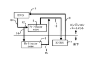
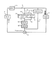
- FIG. 1 is a cooling water circuit diagram of an internal combustion engine 1 including an exhaust heat recovery system according to the first embodiment.
- the cooling water supplied to the internal combustion engine 1 by the water pump 2 exchanges heat with the internal combustion engine 1 in a water jacket provided inside the internal combustion engine 1 and is discharged to the cooling water passage 9.
- the cooling water passage 9 is provided with a radiator 3 that releases the heat of the cooling water whose temperature has been increased by heat exchange with the internal combustion engine 1 into the atmosphere.
- the cooling water passage 9 is branched between the internal combustion engine 1 and the radiator 3 into a heater passage 10 and a transmission oil cooler passage 11.
- the heater passage 10 and the transmission oil cooler passage 11 merge on the downstream side of the exhaust heat recovery unit 7 described later, and further merge with the cooling water passage 9.
- the exhaust heat recovery unit 7 is shown as EHRS (ExhaustExHeat Recirculation System).
- a thermostat 8 is disposed at the junction of the cooling water passage 9, the heater passage 10, and the transmission oil cooler passage 11.
- the thermostat 8 is configured to open when the coolant temperature reaches a predetermined temperature. In the cooling water circuit of the present embodiment, only the cooling water from the heater passage 10 and the transmission oil cooler passage 11 flows to the water pump 2 when the thermostat 8 is closed.
- a water-cooled transmission oil cooler 4 for cooling the hydraulic fluid of the transmission is disposed in the transmission oil cooler passage 11.
- the heater passage 10 is provided with a front heater core 5 and a rear heater core 6 connected in parallel, and an exhaust heat recovery unit 7 connected in series to both of them. More specifically, the heater passage 10 includes a front heater core containing side passage 12 connected to the inlet of the front heater core 5 and a rear heater core containing side passage 14 connected to the inlet of the rear heater core 6. Branched. Then, the front heater core outlet side passage 13 connected to the outlet of the front heater core 5 and the rear heater core outlet side passage 15 connected to the outlet of the rear heater core 6 merge, and downstream from this junction. An exhaust heat recovery unit 7 is arranged.
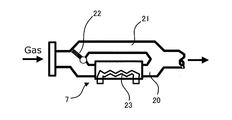
- FIG. 2 is a diagram illustrating an example of the exhaust heat recovery device 7 that can be applied to the present embodiment.
- the exhaust heat recovery device 7 is interposed in the exhaust passage 20 of the internal combustion engine 1, and a heat exchange passage 23 is provided inside the exhaust heat recovery device 7 so as to be exposed to the exhaust gas.
- a heat exchange passage 23 is provided inside the exhaust heat recovery device 7 so as to be exposed to the exhaust gas.
- a bypass passage 21 is provided that branches from the exhaust passage 20, bypasses the exhaust heat recovery device 7, and joins the exhaust passage 20 again.
- a bypass valve 22 for adjusting the flow rate of the exhaust gas flowing through the bypass passage 21 is disposed at a branch portion between the exhaust passage 20 and the bypass passage 21.
- the exhaust heat recovery device 7 is disposed downstream from the confluence of the exhaust passages of the cylinders.
- the exhaust heat recovery unit 7 is disposed downstream from the junction of the exhaust passages of both banks.
- the cooling water exiting the internal combustion engine 1 flows through the cooling water passage 9, the heater passage 10 branched from the cooling water passage 9, and the transmission oil cooler passage 11.
- the cooling water flowing through the heater passage 10 branches and flows into the front heater core 5 and the rear heater core 6, joins on the downstream side of the front heater core 5 and the rear heater core 6, and then enters the exhaust heat recovery unit 7. Inflow.
- the cooling water exiting the exhaust heat recovery unit 7 merges with the cooling water from the transmission oil cooler passage 11, passes through the thermostat 8, and flows into the internal combustion engine 1 again through the water pump 2.
- the thermostat 8 is opened, the cooling water that has passed through the radiator 3 is merged with the cooling water that has passed through the exhaust heat recovery device 7.
- FIG. 3 shows, as a comparative example, a cooling water circuit including the heat recovery system described in JP2006-105464A described above in the same manner as FIG.
- the exhaust heat recovery device 7 is arranged downstream of the junction of the front heater core outlet passage 13 and the rear heater core outlet passage 15 in FIG.
- FIG. 3 there is a difference that it is arranged in the rear heater core outlet passage 15. That is, while the cooling water that has passed through the front heater core 5 and the cooling water that has passed through the rear heater core 6 flow into the exhaust heat recovery device 7 of the present embodiment, the heat recovery device 7 of the comparative example includes There is a difference that only the cooling water that has passed through the rear heater core 6 flows.
- the flow rate of the cooling water passing through the exhaust heat recovery unit 7 is increased as compared with the configuration of FIG. 1, and the amount of exhaust heat recovery is increased. Further, the configuration of the present embodiment makes it difficult for boiling water to boil due to an increase in the flow rate of cooling water as compared with the configuration of FIG.
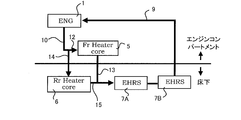
- FIG. 4 is a piping diagram of the cooling water passage when the exhaust heat recovery system in this embodiment is mounted on a vehicle.
- the water pump 2 and the thermostat 8 are omitted. Further, although the front heater core 5 is actually disposed in the vehicle compartment, here, since attention is paid to the piping between the engine compartment and the floor, it is described on the engine compartment side for convenience. The same applies to FIGS. 6, 9, 10, 13, 14, 16, and 17 described later.
- FIG. 5A is a diagram schematically showing the arrangement of the internal combustion engine 1, the front heater core 5, the rear heater core 6, and the exhaust heat recovery device 7 when viewed from the side of the vehicle body.
- FIG. 5B is a cross-sectional view taken along the line VV in FIG. 5A.
- the exhaust heat recovery device 7 is disposed under the floor, and the rear heater core outlet side passage 15 and the front heater core outlet side passage 13 merge under the floor.
- the three pipes of the rear heater core entering side passage 14 branched from the cooling water passage 9, the front heater core outlet side passage 13, and the cooling water passage 9 returning from the exhaust heat recovery device 7 to the internal combustion engine 1 are engine. It will straddle the compartment and under the floor.
- the cooling water passages 9, 13, 14, and 15 are accommodated in the floor tunnel 30 under the floor.
- the floor tunnel 30 also houses the exhaust pipe 31 and the propeller shaft 32, and the cooling water passage accommodated in the floor tunnel 30 includes the exhaust pipe 31 and It arrange
- FIG. 6 is a piping diagram when the junction point of the rear heater core outlet passage 15 and the front heater core outlet passage 13 of FIG. 4 is moved into the engine compartment.
- FIG. 7 is a piping diagram when the exhaust heat recovery unit 7 is not provided.
- the piping extending between the engine compartment and the floor is provided with a rear heater core containing side passage 14 and a cooling water passage returning from the rear heater core 6 to the internal combustion engine 1.
- the piping extending between the engine compartment and the underfloor includes a rear heater core containing side passage 14, a rear heater core outlet side passage 15, a front heater core outlet side passage 13, and a heat recovery unit.
- Four cooling water passages 9 return from the engine 7 to the internal combustion engine 1.
- the piping extending between the engine compartment and the underfloor includes the rear heater core entrance side passage 14 branched from the cooling water passage 9 and the front heater core exit side passage 13 as described above. And a cooling water passage 9 returning from the exhaust heat recovery device 7 to the internal combustion engine 1.
- the piping length of the rear heater core outlet passage 15 is from the rear heater core 6 to the engine compartment in the configuration of FIG. 6, whereas in the configuration of this embodiment, near the exhaust heat recovery unit 7 under the floor. Is enough. That is, according to the present embodiment, it is possible to suppress an increase in the piping path length accompanying the addition of the exhaust heat recovery unit 7 and to suppress a decrease in heater performance.
- the exhaust heat recovery system of the present embodiment includes a cooling water circuit in which a front heater core 5 and a rear heater core 6 are connected in parallel, and an exhaust heat recovery device 7 that recovers heat of exhaust gas of the internal combustion engine 1 into cooling water. And comprising.
- the exhaust heat recovery device 7 is connected in series to both the front heater core 5 and the rear heater core 6.
- the front heater core 5 is disposed in the engine compartment
- the rear heater core 6 is disposed under the floor of the vehicle body
- the cooling water passages 12 and 13 in which the front heater core 5 is disposed and the rear heater.
- a branch point or junction with the cooling water passages 14 and 15 in which the core 6 is disposed is under the floor of the vehicle body.
- the exhaust heat recovery device 7 is located downstream of the junction of the cooling water passage 13 where the front heater core 5 of the cooling water circuit is arranged and the cooling water passage 15 where the rear heater core 6 is arranged. Placed in.
- the exhaust heat recovery unit 7 is connected in series only to the rear heater core 6 as shown in FIG. 3 and is not connected to the front heater core 5 in series. Since the flow rate of the coolant passing through 7 increases, the temperature drop when the coolant joins with the coolant from the transmission oil cooler passage 11 or the like can be suppressed.
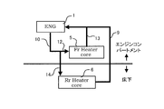
- FIG. 8 is a cooling water circuit diagram of the internal combustion engine 1 including the exhaust heat recovery system according to the second embodiment. The arrangement of the exhaust heat recovery device 7 is different from FIG.
- the exhaust heat recovery device 7 of the present embodiment is disposed on the upstream side of the branch point between the front heater core containing side passage 12 and the rear heater core containing side passage 14 of the heater passage 10.
- the cooling water whose temperature has increased in the exhaust heat recovery unit 7 is reduced in temperature by the merge with the cooling water that has passed through the transmission oil cooler passage 11 and the radiator 3 before the front heater core 5 and the rear heater core 6. Flow into.
- FIG. 9 is a piping diagram of the coolant passage in the vehicle mounted state of the exhaust heat recovery system in the present embodiment.
- the rear heater core 6 and the exhaust heat recovery device 7 are connected by a rear heater core containing side passage 14 that passes only under the floor without passing through the engine compartment.
- the three pipes of the heater passage 10, the front heater core entrance passage 12, and the rear heater core exit passage 15 straddle the engine compartment and the underfloor.
- the pipe connecting the exhaust heat recovery device 7 and the rear heater core 6 is completed only under the floor, as shown in FIG. As compared with the configuration in which the rear heater core containing side passage 14 branches, the pipe length can be shortened.
- the present embodiment as in the first embodiment, it is possible to suppress the deterioration of the layout of the piping path due to the addition of the exhaust heat recovery device 7. Moreover, similarly to 1st Embodiment, the increase in the piping path length accompanying the extension of the exhaust heat recovery device 7 can be suppressed, and the fall of heater performance can be suppressed.
- the exhaust heat recovery device 7 is disposed upstream from the branch point between the front heater core side passage 12 and the rear heater core side passage 14.
- the cooling water whose temperature has risen in the exhaust heat recovery unit 7 is reduced in temperature by the merging with the cooling water that has passed through the transmission oil cooler passage 11 and the radiator 3, before the front heater core 5 and the rear heater core. Since it flows into 6, the heater performance can be improved.
- the third embodiment is different from the first and second embodiments in that it includes a plurality of exhaust heat recovery devices.
- first exhaust heat recovery unit 7A when it is necessary to distinguish a plurality of exhaust heat recovery units, they are referred to as “first exhaust heat recovery unit 7A” and “second exhaust heat recovery unit 7B”. It is set as the collection device 7 ”.
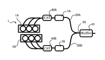
- FIG. 11 is an exhaust path diagram of the internal combustion engine system including the exhaust heat recovery system according to the present embodiment.
- the internal combustion engine 1 is a V-type internal combustion engine including a first bank 1A and a second bank 1B, and the first exhaust passage 20A into which the exhaust passages from the cylinders of the first bank 1A are joined from the upstream side.
- a first exhaust catalyst 40A and a first exhaust heat recovery unit 7A are arranged.
- the second exhaust catalyst 40B and the second exhaust heat recovery device 7B are arranged in the second exhaust passage 20B where the exhaust passages from the respective cylinders of the second bank 1B join.
- the first exhaust passage 20A and the second exhaust passage 20B join together on the downstream side of the first exhaust heat recovery device 7A and the second exhaust heat recovery device 7B to form the exhaust passage 20.
- a muffler 41 for silencing is arranged in the exhaust passage 20.
- FIG. 12 is a cooling water circuit diagram of the internal combustion engine 1 including the exhaust heat recovery system according to the present embodiment.
- the first exhaust heat recovery unit 7A is connected in series to the downstream side of the front heater core 5
- the second exhaust heat recovery unit 7B is connected in series to the downstream side of the rear heater core 6,
- the heat recovery device outlet side passage 42 and the second exhaust heat recovery device outlet side passage 43 merge.
- FIG. 13 is a piping diagram of the cooling water passage when the exhaust heat recovery system according to the present embodiment is mounted on a vehicle.
- the first exhaust heat recovery device outlet side passage 42 and the second exhaust heat recovery device outlet side passage 43 merge under the floor.
- the cooling water passage 9 in which the rear heater core entering side passage 14, the front heater core exit side passage 13, and the first exhaust heat recovery device exit side passage 42 and the second exhaust heat recovery device exit side passage 43 merge is formed. It will straddle the engine compartment and the underfloor. That is, there are three pipes that straddle the engine compartment and the underfloor as in the first and second embodiments.
- the exhaust heat recovery unit 7 is disposed in each of the exhaust passages 20A and 20B from each bank of the V-type internal combustion engine 1, and the first exhaust heat recovery unit 7A is used as the front heater core 5.
- the second exhaust heat recovery unit 7B is connected to the rear heater core 6 in series.
- the fourth embodiment includes two exhaust heat recovery units 7 as in the third embodiment. That is, as shown in FIG. 11, the exhaust heat recovery devices 7A and 7B are arranged in the exhaust paths 20A and 20B from the banks 1A and 1B of the V-type internal combustion engine 1, respectively.
- the cooling water circuit for connecting the front heater core 5 and the rear heater core 6 to the two exhaust heat recovery devices 7A and 7B is different from the third embodiment.
- the difference from the third embodiment will be mainly described.
- FIG. 15 is a cooling water circuit diagram of the internal combustion engine 1 including the exhaust heat recovery system according to the present embodiment.
- the first exhaust heat recovery unit 7 ⁇ / b> A is disposed downstream of the junction of the front heater core outlet side passage 13 and the rear heater core outlet side passage 15.
- the second exhaust heat recovery unit 7B is arranged in series on the downstream side of the first exhaust heat recovery unit 7A.
- FIG. 16 is a piping diagram of the cooling water passage when the exhaust heat recovery system in this embodiment is mounted on a vehicle.
- the front heater core outlet passage 13 and the rear heater core outlet passage 15 merge under the floor.
- the rear heater core entrance side passage 14, the front heater core exit side passage 13, and the cooling water passage 9 on the downstream side of the second exhaust heat recovery device 7B straddle the engine compartment and the underfloor. That is, there are three pipes that straddle the engine compartment and the underfloor as in the first embodiment, the second embodiment, and the third embodiment.
- the first exhaust heat recovery device 7A and the second exhaust heat recovery device 7B disposed in each of the exhaust passages 20A and 20B from each bank of the V-type internal combustion engine 1 are replaced with the front heater.
- the core outlet side passage 13 and the rear heater core outlet side passage 15 are connected in series downstream from the junction.
Landscapes
- Engineering & Computer Science (AREA)
- Chemical & Material Sciences (AREA)
- Combustion & Propulsion (AREA)
- Physics & Mathematics (AREA)
- Thermal Sciences (AREA)
- Mechanical Engineering (AREA)
- Air-Conditioning For Vehicles (AREA)
Abstract
La présente invention concerne un système de récupération de chaleur perdue comprenant: un circuit d'eau de refroidissement dans lequel un radiateur de chauffage pour un appareil de chauffage avant et un radiateur de chauffage pour un appareil de chauffage arrière sont raccordés en parallèle; et un appareil de récupération de chaleur perdue configuré pour réaliser un échange de chaleur avec un gaz d'échappement provenant d'un moteur à combustion interne de sorte que la chaleur du gaz d'échappement soit récupérée par de l'eau de refroidissement. Dans le système de récupération de chaleur perdue selon l'invention, l'appareil de récupération de chaleur perdue est agencé de manière à être raccordé en série à la fois au radiateur de chauffage avant et au radiateur de chauffage arrière afin de récupérer une plus grande quantité de chaleur de gaz d'échappement.
Priority Applications (2)
| Application Number | Priority Date | Filing Date | Title |
|---|---|---|---|
| JP2016535596A JP6380535B2 (ja) | 2014-07-24 | 2014-07-24 | 排熱回収システム |
| PCT/JP2014/069627 WO2016013094A1 (fr) | 2014-07-24 | 2014-07-24 | Système de récupération de chaleur perdue |
Applications Claiming Priority (1)
| Application Number | Priority Date | Filing Date | Title |
|---|---|---|---|
| PCT/JP2014/069627 WO2016013094A1 (fr) | 2014-07-24 | 2014-07-24 | Système de récupération de chaleur perdue |
Publications (1)
| Publication Number | Publication Date |
|---|---|
| WO2016013094A1 true WO2016013094A1 (fr) | 2016-01-28 |
Family
ID=55162649
Family Applications (1)
| Application Number | Title | Priority Date | Filing Date |
|---|---|---|---|
| PCT/JP2014/069627 Ceased WO2016013094A1 (fr) | 2014-07-24 | 2014-07-24 | Système de récupération de chaleur perdue |
Country Status (2)
| Country | Link |
|---|---|
| JP (1) | JP6380535B2 (fr) |
| WO (1) | WO2016013094A1 (fr) |
Cited By (1)
| Publication number | Priority date | Publication date | Assignee | Title |
|---|---|---|---|---|
| CN113191083A (zh) * | 2021-04-30 | 2021-07-30 | 西安交通大学 | 考虑全工况外部参数变化的烟气余热回收系统优化设计方法 |
Citations (5)
| Publication number | Priority date | Publication date | Assignee | Title |
|---|---|---|---|---|
| JPS6282807U (fr) * | 1985-11-14 | 1987-05-27 | ||
| JPH0633780A (ja) * | 1992-07-15 | 1994-02-08 | Isuzu Ceramics:Kenkyusho:Kk | 発電・電動機を持つターボチャージャを備えた多気筒型ガスエンジン |
| JPH1035263A (ja) * | 1996-05-24 | 1998-02-10 | Denso Corp | 車両用暖房装置 |
| JP2009073430A (ja) * | 2007-09-24 | 2009-04-09 | Denso Corp | 車載組電池の温度調節装置 |
| JP2009299567A (ja) * | 2008-06-12 | 2009-12-24 | Toyota Motor Corp | 排熱回収システム |
Family Cites Families (3)
| Publication number | Priority date | Publication date | Assignee | Title |
|---|---|---|---|---|
| JPH01142307U (fr) * | 1988-03-25 | 1989-09-29 | ||
| JP2006327294A (ja) * | 2005-05-24 | 2006-12-07 | Honda Motor Co Ltd | リアヒーター装置 |
| JP4281789B2 (ja) * | 2006-12-06 | 2009-06-17 | トヨタ自動車株式会社 | 排気熱回収装置 |
-
2014
- 2014-07-24 JP JP2016535596A patent/JP6380535B2/ja active Active
- 2014-07-24 WO PCT/JP2014/069627 patent/WO2016013094A1/fr not_active Ceased
Patent Citations (5)
| Publication number | Priority date | Publication date | Assignee | Title |
|---|---|---|---|---|
| JPS6282807U (fr) * | 1985-11-14 | 1987-05-27 | ||
| JPH0633780A (ja) * | 1992-07-15 | 1994-02-08 | Isuzu Ceramics:Kenkyusho:Kk | 発電・電動機を持つターボチャージャを備えた多気筒型ガスエンジン |
| JPH1035263A (ja) * | 1996-05-24 | 1998-02-10 | Denso Corp | 車両用暖房装置 |
| JP2009073430A (ja) * | 2007-09-24 | 2009-04-09 | Denso Corp | 車載組電池の温度調節装置 |
| JP2009299567A (ja) * | 2008-06-12 | 2009-12-24 | Toyota Motor Corp | 排熱回収システム |
Cited By (2)
| Publication number | Priority date | Publication date | Assignee | Title |
|---|---|---|---|---|
| CN113191083A (zh) * | 2021-04-30 | 2021-07-30 | 西安交通大学 | 考虑全工况外部参数变化的烟气余热回收系统优化设计方法 |
| CN113191083B (zh) * | 2021-04-30 | 2022-12-02 | 西安交通大学 | 考虑全工况外部参数变化的烟气余热回收系统优化设计方法 |
Also Published As
| Publication number | Publication date |
|---|---|
| JP6380535B2 (ja) | 2018-08-29 |
| JPWO2016013094A1 (ja) | 2017-04-27 |
Similar Documents
| Publication | Publication Date | Title |
|---|---|---|
| JP4281789B2 (ja) | 排気熱回収装置 | |
| CN105874182B (zh) | 进气冷却装置 | |
| JP2015178807A (ja) | エンジンのシリンダヘッド | |
| JP2011007078A (ja) | 排気再循環装置 | |
| RU2010134817A (ru) | Теплообменник с фрактальной системой труб | |
| JP2009097340A (ja) | Egr装置 | |
| JP6380535B2 (ja) | 排熱回収システム | |
| JP6499326B2 (ja) | 排気熱回収装置 | |
| JP6307512B2 (ja) | 熱電発電機を備えた排ガスシステム | |
| JP7400693B2 (ja) | エンジンの排気循環装置 | |
| JP5637964B2 (ja) | 内燃機関の冷却構造 | |
| CN104685180B (zh) | 用于车辆内燃机的液体冷却系统 | |
| CN103590928B (zh) | 双废气再循环冷却装置 | |
| JP2012167613A (ja) | エンジン | |
| JP2010164021A (ja) | 排気冷却システム | |
| JP2017031929A (ja) | エンジンのegrクーラ | |
| JP6139463B2 (ja) | 内燃機関 | |
| JP4591270B2 (ja) | 内燃機関の排気装置 | |
| JP5381394B2 (ja) | 内燃機関のegrクーラー | |
| JP5907275B2 (ja) | 内燃機関の冷却装置 | |
| JP5918474B2 (ja) | Egr装置 | |
| JP6645479B2 (ja) | エンジンの冷却システム | |
| CN102011638B (zh) | 多缸发动机水冷却结构 | |
| JP2014139418A (ja) | シリンダヘッド | |
| JP2017218930A (ja) | 車両用水冷設備 |
Legal Events
| Date | Code | Title | Description |
|---|---|---|---|
| 121 | Ep: the epo has been informed by wipo that ep was designated in this application |
Ref document number: 14898181 Country of ref document: EP Kind code of ref document: A1 |
|
| ENP | Entry into the national phase |
Ref document number: 2016535596 Country of ref document: JP Kind code of ref document: A |
|
| NENP | Non-entry into the national phase |
Ref country code: DE |
|
| 122 | Ep: pct application non-entry in european phase |
Ref document number: 14898181 Country of ref document: EP Kind code of ref document: A1 |