WO2016013728A1 - Pile à combustible à oxyde solide à segment de type à tube plat et son procédé de fabrication - Google Patents
Pile à combustible à oxyde solide à segment de type à tube plat et son procédé de fabrication Download PDFInfo
- Publication number
- WO2016013728A1 WO2016013728A1 PCT/KR2014/011483 KR2014011483W WO2016013728A1 WO 2016013728 A1 WO2016013728 A1 WO 2016013728A1 KR 2014011483 W KR2014011483 W KR 2014011483W WO 2016013728 A1 WO2016013728 A1 WO 2016013728A1
- Authority
- WO
- WIPO (PCT)
- Prior art keywords
- paste
- cathode
- anode
- centrifugal mixer
- flat
- Prior art date
- Legal status (The legal status is an assumption and is not a legal conclusion. Google has not performed a legal analysis and makes no representation as to the accuracy of the status listed.)
- Ceased
Links
Images











Classifications
-
- H—ELECTRICITY
- H01—ELECTRIC ELEMENTS
- H01M—PROCESSES OR MEANS, e.g. BATTERIES, FOR THE DIRECT CONVERSION OF CHEMICAL ENERGY INTO ELECTRICAL ENERGY
- H01M4/00—Electrodes
- H01M4/86—Inert electrodes with catalytic activity, e.g. for fuel cells
- H01M4/88—Processes of manufacture
-
- H—ELECTRICITY
- H01—ELECTRIC ELEMENTS
- H01M—PROCESSES OR MEANS, e.g. BATTERIES, FOR THE DIRECT CONVERSION OF CHEMICAL ENERGY INTO ELECTRICAL ENERGY
- H01M4/00—Electrodes
- H01M4/86—Inert electrodes with catalytic activity, e.g. for fuel cells
- H01M4/90—Selection of catalytic material
-
- H—ELECTRICITY
- H01—ELECTRIC ELEMENTS
- H01M—PROCESSES OR MEANS, e.g. BATTERIES, FOR THE DIRECT CONVERSION OF CHEMICAL ENERGY INTO ELECTRICAL ENERGY
- H01M8/00—Fuel cells; Manufacture thereof
- H01M8/02—Details
-
- H—ELECTRICITY
- H01—ELECTRIC ELEMENTS
- H01M—PROCESSES OR MEANS, e.g. BATTERIES, FOR THE DIRECT CONVERSION OF CHEMICAL ENERGY INTO ELECTRICAL ENERGY
- H01M8/00—Fuel cells; Manufacture thereof
- H01M8/10—Fuel cells with solid electrolytes
- H01M8/12—Fuel cells with solid electrolytes operating at high temperature, e.g. with stabilised ZrO2 electrolyte
-
- Y—GENERAL TAGGING OF NEW TECHNOLOGICAL DEVELOPMENTS; GENERAL TAGGING OF CROSS-SECTIONAL TECHNOLOGIES SPANNING OVER SEVERAL SECTIONS OF THE IPC; TECHNICAL SUBJECTS COVERED BY FORMER USPC CROSS-REFERENCE ART COLLECTIONS [XRACs] AND DIGESTS
- Y02—TECHNOLOGIES OR APPLICATIONS FOR MITIGATION OR ADAPTATION AGAINST CLIMATE CHANGE
- Y02E—REDUCTION OF GREENHOUSE GAS [GHG] EMISSIONS, RELATED TO ENERGY GENERATION, TRANSMISSION OR DISTRIBUTION
- Y02E60/00—Enabling technologies; Technologies with a potential or indirect contribution to GHG emissions mitigation
- Y02E60/30—Hydrogen technology
- Y02E60/50—Fuel cells
-
- Y—GENERAL TAGGING OF NEW TECHNOLOGICAL DEVELOPMENTS; GENERAL TAGGING OF CROSS-SECTIONAL TECHNOLOGIES SPANNING OVER SEVERAL SECTIONS OF THE IPC; TECHNICAL SUBJECTS COVERED BY FORMER USPC CROSS-REFERENCE ART COLLECTIONS [XRACs] AND DIGESTS
- Y02—TECHNOLOGIES OR APPLICATIONS FOR MITIGATION OR ADAPTATION AGAINST CLIMATE CHANGE
- Y02P—CLIMATE CHANGE MITIGATION TECHNOLOGIES IN THE PRODUCTION OR PROCESSING OF GOODS
- Y02P70/00—Climate change mitigation technologies in the production process for final industrial or consumer products
- Y02P70/50—Manufacturing or production processes characterised by the final manufactured product
Definitions
- the present invention relates to a solid oxide fuel cell. More particularly, the present invention relates to a solid oxide fuel cell, and more particularly, includes an air electrode capable of finding an optimum point of the anode thickness in combination with the anode and obtaining a high output density. It relates to a flat tubular segment solid oxide fuel cell and a method of manufacturing the same.
- a fuel cell is a device that generates electricity directly through a chemical reaction from a fuel, and there are various kinds according to its internal configuration.
- the fuel cell operates by generating electricity generated through an anode, a cathode, an electrolyte, an anode, and an external power through an electrical collector.
- the types of fuel cells are typically polymer electrolyte fuel cells (PEMFC), phosphate acid fuel cells (PAFC), carbonate fuel cells (MCFC), and solid oxide fuel cells.
- PEMFC polymer electrolyte fuel cells
- PAFC phosphate acid fuel cells
- MCFC carbonate fuel cells
- SOFC Solid Oxide Fuel Cell
- As fuel, H 2 , CO, CH 4 , LNG, LPG, CH 3 OH, Diesel, Biogas, Coal gas, etc. are used in various ways, and the electromotive force per unit cell (OCV, Open Circuit Voltage) for hydrocarbon fuels Is about 1.00 ⁇ 1.07V.
- Solid oxide fuel cells are known to have the highest energy conversion efficiency because they operate at high temperatures, and various models are being developed according to structures and shapes.
- the basic materials used are NiO / YSZ cermet in the cathode layer, Yttria-stabilized Zirconia (YSZ) or Gadolium-stabilized Ceria (GDC) in the electrolyte layer, and (La, Sr) MnO 3 , (La, Sr) ( Many material series based on Co, Fe) O 3 and the like are used.
- a cathode, an electrolyte, and an anode are formed into thin plates, alternately stacked with a separator plate, and sealed with a sealant to seal fuel, eg, H 2 gas, with a cathode surface. Air is supplied to the anode surface to generate electricity while maintaining the temperature at about 6501,000.
- a sealant to seal fuel eg, H 2 gas
- the power density generated in the flat plate type is known to be high as 400700 / (peak power standard, about 0.50.7V range), but the physical deformation of the cell due to the high temperature operation, the glass sealing problem, the electrical connection material on the cathode side Due to problems such as increase of electrical resistance and power loss due to oxidation corrosion of electrical collectors, there are obstacles to long-term high temperature stability and enlargement of cells / stacks.
- the tubular solid oxide fuel cell is manufactured in the form of a fuel cell cell in the form of a tube, forming a cathode, an electrolyte, and an anode, and processing and attaching an electrical collector along the length of the tube. In this way, the cells are electrically connected to adjacent cells.
- the cylindrical solid oxide fuel cell consists of a stack in which several tubes are bundled. US 2007/0148523 A1 illustrates a method of electrically connecting each cylindrical cell with a wire or the like.
- the air supply is made inside the tube (in this case made of a cathode-supported type) and the fuel is supplied outside the tube. Therefore, due to the reducing atmosphere, the general metal may be used as an electrical collector outside the tube. Fuel and air can be supplied in reverse as an anode-supported form, but this poses a problem for electrical connectors. Cylindrical in the form of an anode support layer is usually excellent in mechanical properties and long-term high temperature stability, but due to the excessive electrical resistance and increase in output loss in the cell itself, most of the actual electrical output is usually lower than 200 /, and manufacturing cost This is known to be high.
- SOFCs can be manufactured in various types of cells because the electrolyte and the electrode are in a solid state, and are classified into a cathode support type, an cathode support type, and an electrolyte support type according to the fuel cell support.
- Flat SOFCs have high power density, high productivity, and thin electrolyte, but require gas sealing using a separate sealant, and due to the use of a metal connecting material at high temperatures, electrode efficiency is reduced due to chromium volatilization. However, it has a disadvantage of lacking reliability due to low resistance to thermal cycles. Moreover, since flat panel SOFCs are not only difficult to manufacture large-area cells but also easy to manufacture large-capacity stacks, solving these problems becomes a key to practical use.
- Cylindrical SOFCs are evaluated as SOFC designs closest to commercialization because they do not require gas sealing, have excellent mechanical strength, and have been tested for reliability in various test items.
- the cylindrical SOFC has a disadvantage of high internal resistance and low power density because of a long current path.
- the voltage output from the module which is a collection of cells, is low, the power conversion loss during operation is large, and as a result, there is a weakness in efficiency.
- SOFC systems for power generation above 20 kW are mostly adopting stacks using cylindrical or improved cylindrical cells, and in the case of 20 kW or lower, flat cells are also adopted.
- the anode of a segment solid oxide fuel cell plays a role in oxidizing fuel gas to generate hydrogen ions used for electrochemical reactions, and the three-phase interface where oxygen ions and hydrogen ions meet. It forms Triple Phase Boundary (TPB) and releases electrons by electrochemical reaction. It is used as a current collector layer connecting unit cells connected in series, and becomes a passage through which the reaction product H 2 O gas is discharged.
- SISG-SOFC segment solid oxide fuel cell
- the performance of the segmented solid oxide fuel cell is most affected by a voltage drop (iR-drop) caused by a cathode current collector (CCC).
- iR-drop voltage drop
- CCC cathode current collector
- Increasing the thickness of the cathode increases the output density of the SIS-SOFC due to the reduction of the sheet resistance, and may use the highly conductive cathode current collector layer to obtain higher output density characteristics.
- An object of the present invention is to provide a flat-segmented solid oxide fuel cell that can obtain the maximum output density by finding the optimum point of anode thickness in the manufacture of a solid oxide fuel cell.
- Another problem to be solved by the present invention is to provide a flat-segment solid-state solid oxide fuel cell that can obtain a higher power density by using a highly conductive cathode current collector layer material.
- a method for manufacturing a flat-segment solid oxide fuel cell may include mixing NiO and Sc 2 O 3 -CeO 2 -ZrO 2 powders, and then adding ethanol to the mixed powders.
- the wet ball mill proceeds, and after the wet ball mill proceeds to dry in a dryer to form a fine mixed powder, after quantitating the mixed powder, and after adding a solvent (-terpineol) and dispersant Mix using a high speed centrifugal mixer (Planetary Centrifugal Mixer, ARM-310), a binder (organic binder) (Ethyle Celllulose-cp50) and a solvent (-terpineol) after mixing using a high speed centrifugal mixer, the mixing After mixing the powder slurry and the binder, a paste is prepared by using a high-speed centrifugal mixer, the paste is repeatedly milled with a three roll mill, and the mille
- the high speed centrifugal mixer may be manufactured by increasing the mixer speed.
- the solvent (-terpineol) and the addition of a dispersant and then mixing using a high-speed centrifugal mixer (Planetary Centrifugal Mixer, ARM-310), 54.7wt% of the mixed powder by weight
- solvent (-terpineol) is added 24.2wt.%
- fish oil is added 0.5wt.% To the total weight as a dispersant, and then a high-speed centrifugal mixer (ARM-310) is used.
- the mixing may be a process.
- the process of mixing the binder (Ethyle Celllulose-cp50) and the solvent (-terpineol) using a high-speed centrifugal mixer, the binder (organic binder) (Ethyle Celllulose-cp50) to 4.1wt. %, Solvent (-terpineol) may be a process of mixing using a high-speed centrifugal mixer after mixing 16.4wt.% Relative to the total weight.
- a method of manufacturing a flat tubular segmented solid oxide fuel cell including: a sintered flat tubular support; Forming a fuel electrode on the flat tubular support; Forming an electrolyte layer on the anode; Forming a cathode on the electrolyte layer; Located in the outer side of the cathode, and electrically connecting the anode of the unit cell and the cathode of the other unit cell to form a connecting material to enable electrical communication between the unit cells, the step of forming the anode on the flat tubular support, NiO And 5: 5 quantitatively and ScSZ are mixed with a solvent (-Terpineol) and a binder (Ethyl cellulose) with a high-speed centrifugal mixer to form a cathode paste, and the anode paste is coated on the sintered support and then heat treated.
- a solvent -Terpineol
- a binder Etheral mixer
- the process of forming an electrolyte layer on the play electrode, masking the portion to be coated with the connecting material on the unit cell with a masking tape, and after coating the ScSZ heat treatment, GDC (Ce 0.9 ) on the coated ScSZ Gd 0.1 O) may be coated and then sintered.
- the process of coating the anode paste on the sintered support may use a screen printing method.
- a method of manufacturing a flat-segmented solid oxide fuel cell which forms a plasticized flat tubular support and quantifies NiO and ScSZ by 5: 5 on the plasticized flat tubular support.
- the ScSZ-coated anode and heat-treated After forming, after the heat treatment to mask the portion to be formed with a masking tape and coating the ScSZ on the anode using a vacuum slurry coating method, the ScSZ-coated anode and heat-treated, the method of coating the ScSZ In the same manner as in the coating on the ScSZ GDC (Ce 0.9 Gd 0.1 O) and sintering to form an electrolyte layer, LSCF (La 0.6 Sr 0.4 Co 0.2 Fe 0.8 ,) and GDC 5: 5 to quantify to form a cathode composite electrode paste, to form a cathode paste using LSCF, to coat the cathode composite electrode and cathode paste with a screen print on the electrolyte layer, and to coated the cathode composite electrode and cathode
- the paste may be heat-treated to form an air electrode, and may include a connecting material that electrically connects the fuel electrode and the air electrode in series using silver
- the fuel electrode may have a thickness of 14 or more and 40 or less.
- the fuel electrode may have a thickness of 20.
- the process of forming the anode by heat-treating the coated anode paste may be heat-treated at 1000 to 3 hours.
- a method of manufacturing a flat-segmented solid oxide fuel cell comprising mixing LSCF (La 0.6 Sr 0.4 Co 0.2 Fe 0.8 ) and GDC (Ce 0.9 Gd 0.1 O) powder. After ethanol was added to the mixed powder, zirconia ball was added, the ball mill was carried out, dried in a drier and fine powder was formed. After quantifying the mixed powder, a solvent (-terpineol) and a dispersant were mixed.
- LSCF La 0.6 Sr 0.4 Co 0.2 Fe 0.8
- GDC Ce 0.9 Gd 0.1 O
- the speed of the centrifugal mixer is increased to form a cathode functional layer paste, milling the cathode functional layer paste with a three roll mill, and the milled cathode functional layer paste.
- Forming the cathode functional layer using a screen mask it may comprise a step of forming a conductive layer on the air electrode home cathode functional layer.
- the dispersant and the organic binder are heated to 3.33 / min to 200 and maintained for 3 hours, and to 250 and maintained for 2 hours, then to 300, to 300. After heating up to 0.42 / min, it can hold
- the drying process in the dryer can be carried out for 90, 24 hours.
- the ball mill may be a wet ball mill.
- the flat-shaped segmented solid oxide fuel cell may have an improved output due to an increase in three-phase interface, and may have an increased output because no concentration overvoltage occurs.
- the flat-segmented solid oxide fuel cell may obtain higher power density characteristics by using a highly conductive cathode current collector layer material.
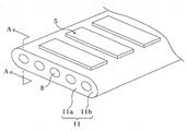
- FIG. 1 is a schematic perspective view of a flat tubular segmented solid oxide fuel cell according to an embodiment of the inventive concept.
- FIG. 2 is a schematic cross-sectional view of a unit cell of a planar segment solid oxide fuel cell cut along the line AA ′ of FIG. 1.
- FIG. 3 is a photograph showing a flat tubular support in a flat tubular segmented solid oxide fuel cell according to an embodiment of the inventive concept.
- FIG. 4 is a graph illustrating thermogravimetric analysis of a cathode paste and a binder in a flat tubular segmented solid oxide fuel cell according to an embodiment of the inventive concept.
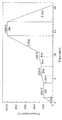
- FIG. 5 is a graph showing the sintering conditions of the anode paste in the flat-shaped segmented solid oxide fuel cell according to an embodiment of the present invention.
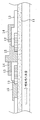
- FIG. 6 is a schematic diagram illustrating a manufacturing process of a unit cell in a flat tubular segmented solid oxide fuel cell according to an embodiment of the inventive concept.
- FIG. 7 is an actual photograph of a three-cell SIS SOFC in a flat segment segmented solid oxide fuel cell according to an embodiment of the inventive concept.
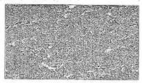
- FIGS. 8A and 8B are photographs showing the anode surface microstructure before and after reduction in a flat tubular segmented solid oxide fuel cell according to an embodiment of the inventive concept.
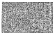
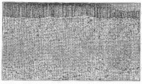
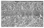
- FIGS. 9A to 9C are enlarged photographs of a fuel electrode according to a thickness of a 5-cell SIS SOFC in a flat tubular segmented solid oxide fuel cell according to an embodiment of the inventive concept.
- FIGS. 10A to 10C are photographs illustrating the microstructure of a fuel electrode according to the thickness of a 5-cell SIS SOFC in a flat tubular segmented solid oxide fuel cell according to an embodiment of the inventive concept.
- FIG. 11 is a graph comparing current-voltage-output curves according to anode thickness in a flat tubular segmented solid oxide fuel cell according to an embodiment of the inventive concept.
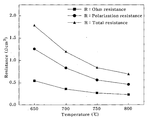
- FIG. 12 is a graph illustrating an AC impedance comparison according to anode thickness in a flat tubular segmented solid oxide fuel cell according to an embodiment of the inventive concept.
- FIG. 13 is a graph comparing maximum output density for each temperature according to anode thickness in a flat tubular segmented solid oxide fuel cell according to an embodiment of the inventive concept.
- FIG. 14 is a graph illustrating sintering conditions of a cathode paste in a flat tubular segmented solid oxide fuel cell according to an embodiment of the inventive concept.
- 15A and 15B are actual photographs of a 5-cell SIS SOFC in a flat-shaped segmented solid oxide fuel cell according to an embodiment of the inventive concept.
- FIG. 16A is a photograph illustrating a fracture surface of a unit cell in a flat tubular segmented solid oxide fuel cell according to an embodiment of the inventive concept.
- FIG. 16B is a photograph showing an interface between an air electrode and an electrolyte in a flat tubular segmented solid oxide fuel cell according to an embodiment of the inventive concept.
- FIG. 16C is a photograph showing an interface between a fuel electrode and a support in a planar segment solid oxide fuel cell according to an embodiment of the inventive concept.
- 16D is a photograph showing an interface between an air electrode and an Ag-glass in a flat-segment solid oxide fuel cell according to an embodiment of the inventive concept.
- 16E is a photograph showing an interface between a fuel electrode and a connector in a flat-segment solid oxide fuel cell according to an embodiment of the inventive concept.
- FIG. 17A and 17B are photographs showing line scaning for identifying components of a cathode functional layer (C.F.L) and a cathode current collecting layer (C.C.L) in a flat-segment segment solid oxide fuel cell according to an embodiment of the inventive concept.
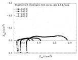
- 18A and 18B are graphs showing a current-voltage-output curve of a 5-cell SIS SOFC using a composite cathode in a flat-shaped segmented solid oxide fuel cell according to an embodiment of the inventive concept.
- 19A and 19B illustrate A.C. of a five-cell SIS SOFC using a composite cathode in a flat tubular segmented solid oxide fuel cell according to an embodiment of the inventive concept. This graph shows the impedance.
- FIG. 20 is a cross-sectional view of the unit cell of the cathode current collector layer LSCF 57 and the composite cathode current collector layer LSCF / LSCo 20 in the planar segmented solid oxide fuel cell according to an embodiment of the inventive concept. This is a graph comparing the impedance.
- top, bottom, top, bottom, or top, bottom, etc. are used to distinguish relative positions in the component.
- the upper part may be called the lower part and the lower part may be named the upper part without departing from the scope of the present invention. .
- FIG. 1 is a schematic perspective view of a flat tubular segmented solid oxide fuel cell according to an embodiment of the inventive concept
- FIG. 2 is a unit cell of a flat tubular segmented solid oxide fuel cell cut along line AA ′ of FIG. 1.
- Figure 3 is a schematic cross-sectional view
- Figure 3 is a photograph showing a flat tubular support in a flat tubular segmented solid oxide fuel cell according to an embodiment of the present invention.
- the planar segment solid oxide fuel cell may include a unit cell 5.
- the unit cell 5 may include a flat tubular support 11, a fuel electrode 12, an electrolyte layer 13, an air electrode 14, and a connecting member 15.
- the flat tubular support 11 is a flow path 8 of the fuel gas, and serves as a support for coating the anode 12.
- the flat tubular support 11 connects the plurality of unit cells 5 and thus may be formed of a non-conductive material.
- the flat tubular support 11 may include a flat portion 11a, a curvature portion 11b, and a plurality of fuel passages 8.
- the unit cell 5 including the fuel electrode 12, the electrolyte layer 13, the air electrode 14, and the connecting member 15, which will be described below, may be disposed on the flat portion 11a.
- the curvature portion 11b may be formed at both ends of the flat portion 11a and may have a curvature having a predetermined radius.
- the fuel passage 8 may have a hollow portion formed inside the flat tubular support 11, and fuel may flow through the fuel passage 8.
- the fuel passage 8 may have a circular cross section, but is not necessarily limited thereto. Referring to FIG. 3, the fuel passage 8 may be formed in an elliptical shape having a different radius of curvature, and may be easily changed by those skilled in the art.
- the anode 12 may be located on the flat tubular support 11.
- the anode 12 may be formed using a slurry prepared by mixing nickel oxide (NiO) powder, yttria stabilized zirconia (YSZ) powder, a binder, a homogeneous agent, a dispersant, a plasticizer and a solvent.
- NiO nickel oxide
- YSZ yttria stabilized zirconia
- the electrolyte layer 13 may be located on the fuel electrode 12.
- the electrolyte layer 13 may be formed by coating a slurry prepared by mixing zirconia (ZrO 2 ) -based powder, a binder, a homogeneous agent, a dispersant, a plasticizer, and a solvent on the fuel electrode 12.
- ZrO 2 zirconia
- the cathode layer 14 is formed in a multilayer structure including an LSCF (L 0.6 S 0.4 C 0.2 F 0.8 ) -GDC layer and an LSCF (L 0.6 S 0.4 C 0.2 F 0.8 ) -LSCo (La 0.6 Sr 0.4 Co). Can be.
- the connecting member 15 may be formed to electrically connect the anode 12 of the unit cell 5 and the cathode 14 of the other unit cell 5 in the flat segmented solid oxide fuel cell.
- the connecting member 15 may be formed using silver-glass paste, but may be used without limitation as long as it is a material commonly used in the art.
- yttria stabilized zirconia is used as a main raw material to form the flat tubular support 11 of the flat tubular segmented solid oxide fuel cell, and activated carbon powder is used as the pore forming agent. Then, 10 to 15 wt% of the activated carbon powder is mixed with respect to 100 wt% of YSZ.
- the yttria stabilized zirconia (YSZ) is yttria stabilized with more than 2 mol% and not more than 5 mol% of yttria Zirconia can be used.
- Yttria stabilized zirconia (YSZ) to which yttria of 2 mol% or less is added has a high strength, so that the thickness of the flat support 11 may be reduced, but a problem arises in that the ion conductivity is low, and 5 mol% or more.
- Yttria stabilized zirconia (YSZ) to which yttria is added has a high ion conductivity, but in order to maintain the strength of the flat support 11 above a certain level, the thickness of the flat support 11 must be increased. Occurs.
- the yttria stabilized zirconia uses yttria stabilized zirconia to which yttria of 2 mol% or more and 5 mol% or less is added, preferably yttria stabilized zirconia to which 3 mol% of yttria is added ( 3YSZ) can be used. If the activated carbon powder is less than 10wt%, there is a problem that the porosity of the flat tubular support is lowered, and if it exceeds 15wt%, the porosity is increased but the compressive strength is lowered.
- the mixture of the mixed YSZ and activated carbon powder is made into a slurry and homogenized by wet ball milling.
- the mixture of the homogenized YSZ and activated carbon powder may be dried in a hot box.
- a paste may be formed by kneading by adding a binder, a plasticizer, a lubricant, and a solvent to the mixture of the powdered YSZ and the activated carbon powder.
- the binder may be a water-based binder YB-13D.
- the binder may serve to bind the powdered mixture and simultaneously form pores with the activated carbon. Distilled water may be used as the solvent.
- the paste may then be extruded into the flat tubular support 11 using an extruder.
- the extrusion process may be extrusion molded so that the moisture of the paste is evenly distributed before extrusion.
- the extruded flat tubular support 11 may be dried.
- the extruded flat tubular support 11 may cause warpage or cracking due to evaporation of the solvent during drying, and may use a thermo-hygrostat to prevent warpage or cracking due to variation in moisture evaporation as a solvent.
- the dried flat tubular support 11 can be plasticized.
- the additive formed in the flat tubular support 11 may be removed, and the strength may be given to the coating process of the anode 12.
- the pre-sintering process conditions are related to the combustion of activated carbon and binders, which are the main additives. If the elevated temperature condition is increased, internal cracks or combustion gases are ignited due to the gas caused by the combustion of activated carbon and binders, and local thermal shock is caused. This may cause breakage of the flat tubular support 11. Accordingly, the activated carbon and the binder may be slowly burned to disperse gas generation, and the grain growth time of the flat tubular support 11 may be given to have the mechanical strength required in the manufacturing process. Subsequently, the sintered flat tubular support 11 can be sintered to complete the flat tubular support 11.
- the anode 12 may be formed on the flat tubular support 11.
- the anode 12 may generally use Cermet, which is a metal and electrolyte mixture.
- the metal and electrolyte mixture Cermet may be a nickel-Yittria stablized zirconia cermet, a nickel-scandia stablized zirconia cermet, or a nickel-gadonia stabilized ceria cermet.
- Gadolinia doped ceria cermet) mixed cermet may be used.
- the anode 12 serves to generate hydrogen ions used for electrochemical reaction by oxidizing fuel gas, and forms a triple phase boudnary (TPB) where oxygen ions and hydrogen ions meet to form electrons in an electrochemical reaction. It can serve to emit.
- TPB triple phase boudnary
- oxygen ions and hydrogen ions meet to form electrons in an electrochemical reaction. It can serve to emit.
- it may be used as a current collector layer connecting the unit cells 5 connected in series, and may be a passage through which the reaction product
- the output is improved by increasing the three-phase interface.
- the output may be reduced due to concentration overvoltage due to the inadequate release of the reaction product.
- the anode 12 may be formed of an anode paste for screen printing.
- thin films produced by screen printing are determined by factors such as printer settings, substrates, pastes and screen masks.
- the microstructure of the thin film is determined by the properties of the paste, which is determined by the particle size of the powder, solid lodaing and additives (eg, organic binders, dispersants, solvents). May be affected.
- additives eg, organic binders, dispersants, solvents.
- an organic binder maintains the shape of the paste after screen printing and maintains the connection of the particles during sintering.
- the dispersant may help to uniformly mix the powder and uniformly disperse the gaps between the particles to serve to sinter well.
- the solvent serves to determine the viscosity of the paste and may also be used to dissolve the binder.
- the SOFC electrolyte paste for screen printing it can be produced with a low binder content (binder content 0.231.0 wt.% Of solid). Increasing the content of the binder increases the bonding strength of the powder during sintering, thereby contributing to the formation of a dense film, but defects such as pinholes and cracks may occur due to the gas generated by the combustion of the binder.
- the binder may be used as a shape maintaining agent, a role of bonding of powder, and a pore forming agent. Since the anode requires the formation of a three-phase interface and a porous microstructure from which the product is discharged, it is necessary to increase the binder content to form pores.
- the electrolyte layer 13 may be formed on the fuel electrode 12.
- the electrolyte layer 13 must have airtightness as it functions as an electron mediator between the fuel electrode 12 and the air electrode 14 and prevents leakage of fuel gas and oxygen-containing gas.
- the electrolyte layer 13 may be formed of a zirconia (ZrO 2 ) -based material.
- the electrolyte layer 13 may be formed of zirconia doped with rare earth elements of 3 to 15 moles.
- the rare earth element may be Sc, Y, La, Ce, Pr, Nd, Pm, Sm, Eu, Gd, Tb, Dy, Ho, Er, Tm, Yb, Lu, and the like.
- the material of the support may be made of GDC, SDC, ScZ and LSGM.
- the electrolyte layer 13 may be formed after masking a portion on which the connecting member 15 is to be coated with a masking tape.
- the cathode 14 may be formed on the electrolyte layer 13.
- Performance of the flat-segment solid oxide fuel cell may have the largest influence on the voltage drop (iR-drop) caused by a cathode current collector layer (CCC).
- CCC cathode current collector layer
- Increasing the thickness of the cathode 14 increases the output density of the SIS-SOFC due to the reduction of the sheet resistance, and may use the highly conductive cathode current collector layer material to obtain higher output density characteristics.
- the flat tube solid oxide fuel cell may manufacture a cathode current collector layer using LSCo (La 0.6 Sr 0.4 Co Oxide) ( ⁇ 1000 S / cm) having high electron conductivity.
- the LSCo can be applied in a functionally graded composite cathode layer method to solve the problem caused by the higher thermal expansion coefficient (Thermal Expansion Coefficient, TEC 17 ⁇ 24x10 -6 ) than the electrolyte.
- the functionally graded composite cathode layer method may be a method for preventing physical separation or cracking at an interface when a material having a different thermal expansion coefficient (TEC) rate is used.
- TEC thermal expansion coefficient
- the cathode 14 of the SIS-SOFC may be fabricated in two layers to play a role.
- the oxygen molecules may be adsorbed by the cathode 14, receive electrons, oxidize to oxygen ions, and then send them to the electrolyte by thermodynamic driving force.
- the cathode current collector layer CCL
- each unit cell 5 constituting the SIS-SOFC is connected in series to supply electrons to assist in oxidation of oxygen.
- it may have a great effect on the increase / decrease of performance due to ohm resistance.
- the cathode functional layer CFL and the cathode current collecting layer CCL are similar to the anode 12 manufactured above, and the cathode 14 should be made of a porous microstructure without cracking.
- a paste having an appropriate viscosity may be manufactured by adjusting the content of the organic binder and the solid loading amount.
- uniform dispersion is important because it is manufactured using two similar powders of LSCF and LSCo.
- 2.5 mg / m 2 of fish oil may be added in proportion to the specific surface area (BET) of the powder.
- the connecting member 15 may be formed outside the cathode 14.
- the connecting member 15 may be formed for electrical communication of the segmented solid oxide fuel cell.
- the connecting member 15 electrically connects the anode 12 of the unit cell 5 and the cathode 14 of the other unit cell 5 in the segmented solid oxide fuel cell to enable electrical communication between the unit cells.
- the connecting member 15 may be formed by coating a silver-glass paste.
- the connecting member 15 should have excellent electrical conductivity and ensure gas sealing properties, and may exhibit excellent electrical conductivity by silver powder included in the silver-glass paste, and may exhibit gas sealing effect by glass powder. have.
- NiO and 10mol% Sc 2 O 3 - 1mol % CeO 2 - to 89mol% ZrO 2 (10Sc1CeSZ) 50 The mixture of the powder with 50wt% (volume ratio: 40vol% Ni, 60vol% 10Sc1CeSZ ).
- step 1) After mixing the mixed powder slurry and binder prepared in step 1) and step 2), use a high speed centrifugal mixer to increase the mixer speed in the following order to make a paste. (500 rpm 5 minutes 1000 rpm 5 minutes 2000 rpm 5 minutes)
- the anode paste prepared in Step 3) is milled by repeating three roll mills twice.
- a pre-made screen mask (Mesh count: SUS 200, Emulsion thickness: 20um) was used, and a fuel electrode having a desired thickness was manufactured by adjusting the number of printings.
- thermogravimetric analysis TGA of an organic binder (Ethyl Cellulose 50) and an anode paste was performed, and thermogravimetric analysis of the anode paste and the binder is shown in FIG. 4.
- the organic binder started pyrolysis from 200 and the combustion was completed at 450, and the produced anode paste can be confirmed that combustion of the additive is performed from 100 to 300 initially.
- FIG. 5 shows the sintering condition of the anode paste in consideration of the binder combustion.
- SIS-SOFC was manufactured as shown in FIG. 6 to manufacture SIS-SOFC.
- NiO and ScSZ were quantified 5: 5 and mixed with a solvent (-Terpineol) and a binder (Ethyl cellulose) by using a high-speed centrifugal mixer to prepare a cathode paste.
- the anode paste prepared using the screen mask was coated on the 3YSZ sintered support, and the thickness of the anode was adjusted by increasing the number of screen printing, and heat-treated at 1000 to 3 hours.
- the ScSZ was coated using a vacuum slurry coating method and heat-treated again at 1000 for 3 hours, and coated with GDC (Ce 0.9 Gd 0.1 O) in the same manner. After sintering at 1400 for 5 hours.
- LSCF La 0.6 Sr 0.4 Co 0.2 Fe 0.8 ,
- GDC GDC
- FIG. 9A to 9C enlarged photographs of the anode part of the unit cell in which the anode (Ni / ScSZ) thicknesses are 14 (FIG. 9A), 20 (FIG. 9B), and 40 (FIG. 9C) are shown.
- FIG. 8A and FIG. 8B in which only the anode was screen printed to observe the microstructure, it was confirmed that nickel, Scandia stabilized zirconia, and a pore network structure were formed well. This indicates that the three-phase interface is well achieved, and that the pores can smoothly supply fuel gas and discharge product.
- FIG. 10A to 10C the overall microstructure of the unit cell of the 3-cell SIS-SOFC fabricated from the anode (Ni / ScSZ) 14 (FIG. 10A), 20 (FIG. 10B), and 40 (FIG. 10C) is illustrated. . Except for the anode, the electrolyte ScSZ ⁇ 9, the interlayer GDC ⁇ 3, and the cathode composite electrodes (LSCF / GDC, LSCF, LSCF / LSCo, LSCo) ⁇ 27 can be confirmed to be the same.
- the anode (Ni / ScSZ) 14 has a maximum power density of 315 mW / cm 2
- the anode (Ni / ScSZ) 20 has a maximum power density of 520 mW / cm 2
- the anode (Ni / ScSZ) 40 has a maximum power density of 450 mW / cm 2 is shown.
- the increase in the maximum power density of about 66% was confirmed when the anode was increased from 14 to 20.
- the maximum power density decrease of about 14% was confirmed when the anode 20 was increased from 40 to 40, which is caused by the concentration overvoltage caused by the insufficiency of the supply of fuel gas and the discharge of the product as the anode thickness increased.
- a current-voltage-output comparison according to anode thickness is shown at 750.
- the anode 14 measured the ohm resistance 0.4641 cm 2 , the polarization resistance 0.6440 cm 2 , the anode 20 measured the ohm resistance 0.2737 cm 2 , the polarization resistance 0.5626 cm 2 , the anode 40 measured the ohm resistance 0.3274 cm 2 , and the polarization resistance 0.6074 cm 2 .
- the ohmic resistance decreased by about 41% and the polarization resistance decreased by about 13%. In comparison with 20 and 40, ohmic resistance increased about 20% and polarization resistance increased about 8%.
- the maximum power density was shown at 20 and slightly decreased at 40, and it was found to be in agreement with the I-V curve. This may be due to concentration overvoltage due to thickness and interference with the release of fuel reaction products at TPB. Referring to FIG. 12, an AC impedance comparison according to anode thickness is shown at 750.
- FIG. 13 a comparison of the maximum power density for each temperature according to the thickness of the anode (Ni / ScSZ) is shown. It can be seen that as the temperature increases from 600 to 800, a difference in the maximum power density of the anode thickness 14 and 20 occurs. As the temperature increases, the cell having a thickness of 20 in the anode has a lower activation overvoltage at the three-phase interface than the cell having a thickness of 14 in the anode, and the output increases with the effect of increasing the ion conductivity of the electrolyte and decreasing the cathode activation overvoltage. In addition, in the case of the anode 40, the ohmic resistance of 14 decreased by 30%, but the polarization resistance decreased by 6%. This result indicates that as the thickness of the anode increases, the increase of the three-phase interface contributes to a positive effect, but when it exceeds the optimum point, the output decreases due to factors such as fuel gas supply and product discharge.
- organic binder (Ethyle Celllulose-cp50) was mixed with 4.06wt.% Of total weight and solvent (-terpineol) with 12.19wt.% Of total weight. Mix for 5 minutes.
- step 1) After mixing the mixed powder slurry and binder prepared in step 1) and step 2), use a high-speed centrifugal mixer to increase the mixer speed in the following order to prepare a paste. (500rpm 5min 1000rpm 5min 2000rpm 5 minute)
- the cathode functional layer paste prepared in Step 3) is milled by repeating three roll mills twice.
- a cathode functional layer having a desired thickness was manufactured by adjusting the number of printing using a pre-made screen mask (Mesh count: SUS 200, Emulsion thickness: 20).
- the organic binder (Ethyle Celllulose-cp50) and the solvent (-terpineol) were mixed by the total weight using the ratio of Table 3, and then 5 minutes at 2000 rpm using a high speed centrifugal mixer. Mixed during.
- step 1) After mixing the mixed powder slurry and binder prepared in step 1) and step 2), use a high-speed centrifugal mixer to increase the mixer speed in the following order to prepare a paste. (500rpm 5min 1000rpm 5min 2000rpm 5 minute)
- the cathode collector layer paste prepared in Step 3) is milled by repeating three roll mills twice.
- the sintering conditions were stepped up at 200 ⁇ 300 step by step considering the combustion of the dispersant (fish oil) and organic binder (Ethyl Cellulose 50). After heating up to 3.33 / min up to 200 was maintained for 3 hours, after heating up to 0.56 / min up to 250 and maintained for 2 hours, after heating up to 0.42 / min up to 300 and maintained for 1 hour, the additives were gradually burned and cracked. Was prevented.
- the arrival of oxygen to the three-phase interface of the cathode functional layer is important.
- to prevent particle growth and increase the temperature increase rate to 3.81 / min to 1100, which is a sintering temperature in order to produce a porous microstructure particle growth was prevented, and it was maintained for 2 hours to prevent sintering into a dense film.
- 14 shows the sintering conditions of the cathode paste in consideration of the binder combustion.
- NiO and ScSZ were 5: 5 quantified to prepare SIS-SOFC, and then mixed with a solvent (-Terpineol) and a binder (Ethyl cellulose) by using a high-speed centrifugal mixer to prepare an anode paste.
- the anode paste prepared using the screen mask was coated on the 3YSZ sintered support, and the thickness of the anode was adjusted by increasing the number of screen printings, and heat-treated at 1000 for 3 hours.
- the ScSZ was coated using a vacuum slurry coating method and heat-treated again at 1000 for 3 hours, and coated with GDC (Ce 0.9 Gd 0.1 O) in the same manner. After sintering at 1400 for 5 hours.
- LSCF La 0.6 Sr 0.4 Co 0.2 Fe 0.8 ,
- GDC GDC
- the fracture surface microstructure of the 5 cell SIS-SOFC is shown. It can be seen that the anode (Ni / ScSZ) ⁇ 20, the electrolyte (ScSZ) ⁇ 9, the interlayer (GDC) ⁇ 3, the cathode composite electrode (LSCF / GDC, LSCF, LSCF / LSCo, LSCo) ⁇ 27.
- the interface between the cathode functional layer (CFL LSCF / GDC) and the electrolyte is porous, and it can be confirmed that the electrolyte and the cathode functional layer are well connected, and the sintering is performed without the presence of cracks and large growth particles to the ends of the cathode. It was confirmed.
- the connection was well performed without peeling or cracking, and the barrier layer formed in the middle of the anode and the support may be formed during the vacuum coating of the ScSZ thin film (about 2 to 3).
- Cell performance measurements show a porous membrane that does not affect fuel gas permeation and product emissions.
- the sealing and connection state of the coated connecting material (Ag-glass) was confirmed.
- the cathode-connecting material was well attached to the cathode without peeling off, and the connecting material was coated without pores on the anode to prevent leakage of fuel gas, and each unit cell was connected.
- FIG. 17A and 17B show line scans for each element for identifying the components of the cathode functional layer (C.F.L) and the cathode current collector layer (C.C.L).
- the cathode functional layer (LSCF / GDC) was manufactured to about 7-8, and the composite cathode current collector layer (LSCF / LSCo) was manufactured to 19-20.
- the Cobalt (Co) content was increased and the Iron (Fe) content was decreased.
- paste-1 (LSCF 100%), paste-2 (LSCF 70%, LSCo 30%), paste-3 (LSCF 50%, LSCo 50%), paste-4 (LSCF 30%, LSCo 70%), paste It can be seen that the composite electrode of LSCF and LSCo is well formed up to -5 (LSCo 100%).
- the fuel cell was operated at the temperature range of 650 ⁇ 800 under the condition of 300 sccm of hydrogen flow and 1.5L / min of air.
- the maximum output density of 238mW / cm 2 (0.95W) at 700 the maximum output density of 370mW / cm 2 (1.48W), a maximum output density in 750 523mW / cm 2 (2.09W) , the maximum power density of 800 at 650 618 mW / cm 2 (2.47 W) performance.
- the output density is shown in FIG. 18A, and the output is shown in FIG. 18B.
- ohmic resistance was reduced by about 47% and polarization resistance was increased by about 5% compared to the cathode collector LSCF 57 at 750.
- the maximum power density increased by about 1.8 times.
- the application of a highly conductive composite cathode current collector to the SIS-SOFC can reduce the iR-drop in the direction of current propagation, which acts as a resistance loss factor.
- high-conductivity cathode materials can be used to reduce cathode polarization resistance and ohmic resistance, resulting in high power density.
Landscapes
- Chemical & Material Sciences (AREA)
- Engineering & Computer Science (AREA)
- Chemical Kinetics & Catalysis (AREA)
- Electrochemistry (AREA)
- General Chemical & Material Sciences (AREA)
- Manufacturing & Machinery (AREA)
- Life Sciences & Earth Sciences (AREA)
- Sustainable Development (AREA)
- Sustainable Energy (AREA)
- Materials Engineering (AREA)
- Inert Electrodes (AREA)
- Fuel Cell (AREA)
Abstract
Un procédé de fabrication d'une pile à combustible à oxyde solide à segment de type à tube plat, selon un mode de réalisation du concept technique de la présente invention, peut comprendre : le mélange de poudre de NiO et de Sc2O3-CeO2-ZrO2 ; l'ajout d'éthanol à la poudre mixte, l'ajout d'une bille de zircone à celle-ci, et ensuite la conduite d'un broyage à billes humide ; après le broyage à billes humide, le séchage de la poudre mixte dans un séchoir, et ensuite la formation d'une poudre mixte fine ; la quantification de la poudre mixte, l'ajout d'un solvant (terpinéol) et d'un agent de dispersion, et ensuite le mélange de la poudre mixte au moyen d'un mélangeur centrifuge à haute vitesse (mélangeur centrifuge planétaire, ARM-310) ; le mélange d'un liant (liant organique) (éthylcellulose-cp50) et du solvant (terpinéol), et ensuite le mélange du mélange au moyen du mélangeur centrifuge à haute vitesse ; le mélange de la suspension concentrée de poudre mixte et du liant et ensuite, la production d'une pâte au moyen du mélangeur centrifuge à haute vitesse ; le broyage répété de la pâte avec un broyeur à trois rouleaux ; et la formation d'une anode à partir de la pâte broyée au moyen d'un masque de sérigraphie.
Applications Claiming Priority (2)
| Application Number | Priority Date | Filing Date | Title |
|---|---|---|---|
| KR20140094120A KR101510402B1 (ko) | 2014-07-24 | 2014-07-24 | 평관형 세그먼트 고체산화물 연료전지 및 그 제조방법 |
| KR10-2014-0094120 | 2014-07-24 |
Publications (1)
| Publication Number | Publication Date |
|---|---|
| WO2016013728A1 true WO2016013728A1 (fr) | 2016-01-28 |
Family
ID=51755484
Family Applications (1)
| Application Number | Title | Priority Date | Filing Date |
|---|---|---|---|
| PCT/KR2014/011483 Ceased WO2016013728A1 (fr) | 2014-07-24 | 2014-11-27 | Pile à combustible à oxyde solide à segment de type à tube plat et son procédé de fabrication |
Country Status (2)
| Country | Link |
|---|---|
| KR (1) | KR101510402B1 (fr) |
| WO (1) | WO2016013728A1 (fr) |
Cited By (1)
| Publication number | Priority date | Publication date | Assignee | Title |
|---|---|---|---|---|
| CN115020716A (zh) * | 2021-12-31 | 2022-09-06 | 浙江氢邦科技有限公司 | 一种燃料电池及其平管固体氧化物燃料电池功能层制备方法 |
Families Citing this family (2)
| Publication number | Priority date | Publication date | Assignee | Title |
|---|---|---|---|---|
| CN106450396A (zh) * | 2016-11-15 | 2017-02-22 | 东莞市联洲知识产权运营管理有限公司 | 一种管状高温固体氧化物燃料电池的制备方法 |
| KR102123721B1 (ko) * | 2017-03-29 | 2020-06-16 | 주식회사 엘지화학 | 애노드, 전극 구조체, 이를 포함하는 연료 전지 및 이의 제조방법 |
Citations (5)
| Publication number | Priority date | Publication date | Assignee | Title |
|---|---|---|---|---|
| KR20110022907A (ko) * | 2009-08-28 | 2011-03-08 | 쌍용머티리얼 주식회사 | 평관형 고체 산화물 연료전지 모듈 |
| KR20120051874A (ko) * | 2010-11-15 | 2012-05-23 | 한국에너지기술연구원 | 연료극 지지체식 평관형 고체산화물 연료전지의 단위 셀 및 그 제조방법 |
| KR101341969B1 (ko) * | 2012-10-15 | 2013-12-16 | 한국에너지기술연구원 | 세그먼트형 고체산화물 연료전지 서브모듈, 이의 제조방법 및 이를 이용한 세그먼트형 고체산화물 연료전지 모듈 |
| KR20140059540A (ko) * | 2012-11-08 | 2014-05-16 | 한국에너지기술연구원 | 세그먼트형 고체산화물 연료전지 모듈 및 그 제조방법 |
| KR20140087665A (ko) * | 2012-12-31 | 2014-07-09 | 한국에너지기술연구원 | 평관형 세그먼트 고체산화물 연료전지 및 그 제조방법 |
Family Cites Families (1)
| Publication number | Priority date | Publication date | Assignee | Title |
|---|---|---|---|---|
| WO2011083842A1 (fr) * | 2010-01-07 | 2011-07-14 | 株式会社エクォス・リサーチ | Appareil pour la production de couche catalytique pour une pile à combustible, procédé de production d'une couche catalytique pour pile à combustible, solution polyélectrolyte et procédé de production de solution polyélectrolyte |
-
2014
- 2014-07-24 KR KR20140094120A patent/KR101510402B1/ko active Active
- 2014-11-27 WO PCT/KR2014/011483 patent/WO2016013728A1/fr not_active Ceased
Patent Citations (5)
| Publication number | Priority date | Publication date | Assignee | Title |
|---|---|---|---|---|
| KR20110022907A (ko) * | 2009-08-28 | 2011-03-08 | 쌍용머티리얼 주식회사 | 평관형 고체 산화물 연료전지 모듈 |
| KR20120051874A (ko) * | 2010-11-15 | 2012-05-23 | 한국에너지기술연구원 | 연료극 지지체식 평관형 고체산화물 연료전지의 단위 셀 및 그 제조방법 |
| KR101341969B1 (ko) * | 2012-10-15 | 2013-12-16 | 한국에너지기술연구원 | 세그먼트형 고체산화물 연료전지 서브모듈, 이의 제조방법 및 이를 이용한 세그먼트형 고체산화물 연료전지 모듈 |
| KR20140059540A (ko) * | 2012-11-08 | 2014-05-16 | 한국에너지기술연구원 | 세그먼트형 고체산화물 연료전지 모듈 및 그 제조방법 |
| KR20140087665A (ko) * | 2012-12-31 | 2014-07-09 | 한국에너지기술연구원 | 평관형 세그먼트 고체산화물 연료전지 및 그 제조방법 |
Cited By (2)
| Publication number | Priority date | Publication date | Assignee | Title |
|---|---|---|---|---|
| CN115020716A (zh) * | 2021-12-31 | 2022-09-06 | 浙江氢邦科技有限公司 | 一种燃料电池及其平管固体氧化物燃料电池功能层制备方法 |
| CN115020716B (zh) * | 2021-12-31 | 2024-04-05 | 浙江氢邦科技有限公司 | 一种燃料电池及其平管固体氧化物燃料电池功能层制备方法 |
Also Published As
| Publication number | Publication date |
|---|---|
| KR20140108197A (ko) | 2014-09-05 |
| KR101510402B1 (ko) | 2015-04-13 |
Similar Documents
| Publication | Publication Date | Title |
|---|---|---|
| Wang et al. | A study of multilayer tape casting method for anode-supported planar type solid oxide fuel cells (SOFCs) | |
| KR101796502B1 (ko) | 지지체식 연결재 코팅막의 제조 방법, 및 이로부터 제조된 지지체식 연결재 코팅막을 포함하는 지지체식 세라믹 연결재 | |
| US20060024547A1 (en) | Anode supported sofc with an electrode multifunctional layer | |
| Shen et al. | Co-sintering anode and Y2O3 stabilized ZrO2 thin electrolyte film for solid oxide fuel cell fabricated by co-tape casting | |
| Lei et al. | Ni-based anode-supported Al2O3-doped-Y2O3-stabilized ZrO2 thin electrolyte solid oxide fuel cells with Y2O3-stabilized ZrO2 buffer layer | |
| WO2022119284A1 (fr) | Procédé de fabrication d'une pile à combustible à céramique protonante, et pile à combustible à céramique protonante ainsi fabriquée | |
| WO2016200206A1 (fr) | Composition de cathode, cathode et pile à combustible la comprenant | |
| Pillai et al. | Short-period segmented-in-series solid oxide fuel cells on flattened tube supports | |
| WO2019050301A1 (fr) | Interconnexion pour une pile à combustible à oxyde solide, son procédé de fabrication et pile à combustible à oxyde solide | |
| KR101341969B1 (ko) | 세그먼트형 고체산화물 연료전지 서브모듈, 이의 제조방법 및 이를 이용한 세그먼트형 고체산화물 연료전지 모듈 | |
| Le et al. | Fabrication and evaluation of anode and thin Y2O3-stabilized ZrO2 film by co-tape casting and co-firing technique | |
| US11909076B2 (en) | Compliant contact material for fuel cells and method of making thereof | |
| WO2016013728A1 (fr) | Pile à combustible à oxyde solide à segment de type à tube plat et son procédé de fabrication | |
| Zhao et al. | Fabrication and characterization of a cathode-supported tubular solid oxide fuel cell | |
| WO2023038167A1 (fr) | Pile à combustible à oxyde solide à support métallique comprenant une couche de contact | |
| KR20120034508A (ko) | 세그먼트형 고체산화물 연료전지 서브모듈, 이의 제조방법 및 이를 이용한 세그먼트형 고체산화물 연료전지 모듈 | |
| JP2001283877A (ja) | 固体電解質型燃料電池の単電池、およびその製造方法 | |
| KR101054549B1 (ko) | 고체산화물 연료전지용 전해질 및 그 제조방법, 상기 전해질을 이용한 단위 전지 및 그 제조방법 | |
| WO2023243778A1 (fr) | Électrode hautement active par une commande de microstructure à l'aide d'un procédé de pulvérisation ultrasonore, son procédé de préparation, et pile à combustible à oxyde solide la comprenant | |
| JP5214227B2 (ja) | 横縞型固体酸化物形燃料電池スタック及びその作製方法 | |
| KR101522839B1 (ko) | 프로톤 전도성 고체 산화물 연료전지용 공기극의 제조방법 및 이를 이용한 프로톤 전도성 고체 산화물 연료전지용 공기극 | |
| WO2019112115A1 (fr) | Procédé de fabrication d'un matériau de connexion en céramique de type support et matériau de connexion en céramique de type support ainsi fabriqué | |
| WO2019050324A1 (fr) | Pile à combustible à oxyde solide et module de batterie la comprenant | |
| WO2016190699A1 (fr) | Particules d'oxyde, cathode les comprenant, et pile à combustible les comprenant | |
| KR101424701B1 (ko) | 세그먼트형 고체산화물 연료전지 모듈 및 그 제조방법 |
Legal Events
| Date | Code | Title | Description |
|---|---|---|---|
| 121 | Ep: the epo has been informed by wipo that ep was designated in this application |
Ref document number: 14898351 Country of ref document: EP Kind code of ref document: A1 |
|
| NENP | Non-entry into the national phase |
Ref country code: DE |
|
| 122 | Ep: pct application non-entry in european phase |
Ref document number: 14898351 Country of ref document: EP Kind code of ref document: A1 |