WO2016016946A1 - Dispositif de dégazage - Google Patents
Dispositif de dégazage Download PDFInfo
- Publication number
- WO2016016946A1 WO2016016946A1 PCT/JP2014/069938 JP2014069938W WO2016016946A1 WO 2016016946 A1 WO2016016946 A1 WO 2016016946A1 JP 2014069938 W JP2014069938 W JP 2014069938W WO 2016016946 A1 WO2016016946 A1 WO 2016016946A1
- Authority
- WO
- WIPO (PCT)
- Prior art keywords
- deaeration
- tube
- tubes
- degassing
- loop
- Prior art date
- Legal status (The legal status is an assumption and is not a legal conclusion. Google has not performed a legal analysis and makes no representation as to the accuracy of the status listed.)
- Ceased
Links
Images


Classifications
-
- B—PERFORMING OPERATIONS; TRANSPORTING
- B01—PHYSICAL OR CHEMICAL PROCESSES OR APPARATUS IN GENERAL
- B01D—SEPARATION
- B01D63/00—Apparatus in general for separation processes using semi-permeable membranes
- B01D63/06—Tubular membrane modules
- B01D63/069—Tubular membrane modules comprising a bundle of tubular membranes
-
- B—PERFORMING OPERATIONS; TRANSPORTING
- B01—PHYSICAL OR CHEMICAL PROCESSES OR APPARATUS IN GENERAL
- B01D—SEPARATION
- B01D19/00—Degasification of liquids
-
- B—PERFORMING OPERATIONS; TRANSPORTING
- B01—PHYSICAL OR CHEMICAL PROCESSES OR APPARATUS IN GENERAL
- B01D—SEPARATION
- B01D61/00—Processes of separation using semi-permeable membranes, e.g. dialysis, osmosis or ultrafiltration; Apparatus, accessories or auxiliary operations specially adapted therefor
Definitions
- the present invention relates to a deaeration device for removing gases and bubbles dissolved in a liquid, and more particularly, a gas-liquid suitable for removing gases and bubbles from a mobile phase of a liquid chromatograph.
- the present invention relates to a degassing device using a depressurization method using a separation membrane.
- a mobile phase stored in a mobile phase container is sucked by a liquid feed pump and fed to a column via a sample injector.
- a sample solution is injected from the sample injector into the mobile phase at a predetermined timing, the sample solution is pushed by the mobile phase and introduced into the column, and various components in the sample solution are moved in the time direction while passing through the column.
- Components contained in the eluate are detected by a detector such as a photodiode array (PDA) detector, and a detection signal corresponding to the concentration of each component is obtained. Based on this detection signal, a chromatogram showing a change in signal intensity over time is created.
- PDA photodiode array
- a mobile phase fed at a high pressure by a liquid feed pump contains a large amount of gas (air, etc.) and bubbles are generated in a column or detector cell, peak deformation in the chromatogram or This may cause spike noise. Further, if the amount of gas (mainly oxygen) dissolved in the mobile phase reaching the detector changes, it causes factors such as baseline fluctuation and drift in the chromatogram. Furthermore, if bubbles are sent to the liquid feed pump due to the generation of bubbles in the mobile phase container, liquid feed failure may occur in the pump, resulting in fluctuations in peak holding time.
- gas air, etc.
- a degassing device for removing dissolved gas and bubbles in the mobile phase is provided between the mobile phase container and the liquid feed pump. It is provided in the flow path.
- a deaeration device using this method (hereinafter, a deaeration device using a vacuum degassing method using a gas-liquid separation membrane is simply referred to as a deaeration device).
- a deaeration device using a vacuum degassing method using a gas-liquid separation membrane is simply referred to as a deaeration device.
- a deaeration device using a vacuum degassing method using a gas-liquid separation membrane is simply referred to as a deaeration device.
- Is a deaeration made of a gas-permeable material for example, PTFE (Polytetrafluoroethylene) -based synthetic resin
- PTFE Polytetrafluoroethylene
- the deaeration tube may be lengthened. However, if this is done, the flow path resistance increases, and the liquid feeding capacity of the liquid feeding pump needs to be increased. Therefore, by thinning the wall of the tube as much as possible within the range that can withstand the liquid supply pressure, the inner diameter size is increased with respect to the same outer diameter size to increase the flow path cross-sectional area, and the device has been devised to reduce the flow path resistance. Yes.
- the vacuum chamber has a small internal volume. Therefore, as shown in FIG. 4, a configuration is adopted in which a long deaeration tube 14 is wound in a loop shape and stored in a small-sized vacuum chamber 10. Thereby, high deaeration performance can be achieved while reducing the size of the apparatus.
- degassing as described above is performed in a plurality of flow paths between a plurality of mobile phase containers storing different mobile phases and a valve for mixing the plurality of mobile phases.
- Each device is arranged.
- Degassing mobile phase 5 Vacuum degassing using gas-liquid separation membrane
- Shimadzu Corporation [Search July 25, 2014]
- the above-described conventional degassing apparatus has a problem that, even though it has not been used for a long time, cracks may occur in the degassing tube and liquid leakage may occur, making measurement impossible during the process. there were.
- the present invention has been made in view of these problems, and an object of the present invention is to provide a deaeration device that can prevent the occurrence of liquid leakage by preventing the occurrence of cracks in the deaeration tube. It is to provide.
- the inventor repeated experiments to find out the cause of cracks in the degassing tube, and elucidated the following crack generation mechanism. That is, when the mobile phase flows through the deaeration tube by the suction action of the liquid feed pump, the flow may be strong or weak (that is, pulsating).
- the flow may be strong or weak (that is, pulsating).
- a phenomenon in which an intermittent flow in which the flow of the mobile phase in the degassing tube temporarily stops and then flows again in a short cycle occurs due to frequent switching of the valve for mixing the mobile phase. Often there is. When such a phenomenon occurs, it has been found that the deaeration tube swings in the vacuum chamber.
- the present invention made in order to solve the above-described problems is a chamber to be evacuated, a chamber housed in the chamber, and both ends thereof held by connection portions fixed to the chamber.
- a degassing tube made of a gas-permeable material that has a loop-like portion wound around the circumference and loops in a loop and allows gas to pass while not allowing liquid to pass through.
- the deaeration device for taking out and discharging the contained gas out of the deaeration tube through the wall surface of the deaeration tube, It is characterized by comprising a rocking restraining means for restraining rocking of the loop portion of the deaeration tube.
- the swing suppression means may integrate a plurality of tubes at least at a part of the loop-shaped portion.
- the swing suppression means can be, for example, a string-like or sheet-like binding member that binds a plurality of tubes together.
- a cylindrical member that can be inserted through a plurality of tubes, and a binding member that can bundle a plurality of tubes by contraction due to heat, light, or other physical stimulus It can also be used.
- the swing suppression means may be a coupling member that integrates a plurality of tubes with an adhesive or an adhesive that bonds a part of the outer wall surfaces of the tubes.
- the loop shape extends from both ends of the deaeration tube held by the connection part in the deaeration tube. It is preferable to integrate a plurality of tubes at three or more sites including two sites that start to bend after being linearly extended to the portion and at least one location of the other loop-shaped portion.
- the binding member is a member that binds a plurality of tubes
- the binding member is preferably made of a material that is softer and more resistant to chemicals than the gas-permeable material that constitutes the degassing tube.
- the deaeration tube is not deformed or crushed, and a flow path in the tube can be secured.
- the gas taken out through the wall surface of the deaeration tube is a corrosive gas or the like, it is possible to prevent the binding member from being damaged and being released from the binding.
- the swing suppression member may be a holding member that holds each tube independently so that at least a part of the loop-shaped portion maintains a spacing between adjacent tubes.
- the holding member is a member in which a plurality of substantially C-shaped holding portions for holding the tubes are connected.
- the adjacent tubes in a loop-shaped part do not contact
- the deaeration device of the present invention even when the flow of liquid in the deaeration tube becomes a pulsating flow or becomes intermittent, rubbing between the deaeration tubes, the inner wall surface of the deaeration tube and the vacuum chamber Can be prevented or reduced. As a result, it is possible to prevent the deaeration tube from becoming thin due to undesired friction, so that it is possible to avoid the occurrence of cracks in the deaeration tube and to prevent liquid leakage.
- FIG. 1 is a configuration diagram of a deaeration device and its surroundings when a deaeration device according to an embodiment of the present invention is used in a liquid chromatograph.
- the top view which shows the state of the deaeration tube in the deaeration apparatus of a present Example.
- Schematic which shows arrangement
- FIG. 1 is a configuration diagram of a deaeration device and its surroundings when the deaeration device of this embodiment is used in a liquid chromatograph
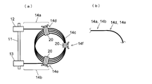
- FIG. 2 is a plan view showing a state of a deaeration tube in the degassing device of this embodiment. .
- the deaeration device 1 of the present embodiment includes a box-shaped vacuum chamber 10 that can be sealed, a vacuum channel 15 having one end connected to the vacuum chamber 10, and a vacuum pump 16 provided on the vacuum channel 15. And a pressure sensor 17 connected to the vacuum flow path 15 between the vacuum chamber 10 and the vacuum pump 16.
- the chamber lid portion 11 constituting one wall surface of the vacuum chamber 10 includes two flow path connection portions 12 and 13 for connecting the flow path inside the vacuum chamber 10 and the external flow path.
- the deaeration tube 14 made of a gas permeable material that allows gas to pass but prevents liquid from passing is housed in the vacuum chamber 10 in a state of being wound around a plurality of loops as shown in FIG. Both ends thereof are connected to the flow path connecting portions 12 and 13.
- one flow path connection portion 12 is connected to the other end of the mobile phase introduction flow path 3, one end of which is connected to the mobile phase container 2 in which the mobile phase is stored.
- One end of the mobile phase derivation flow path 4 reaching the liquid feed pump 5 is connected to the path connection portion 13. That is, the mobile phase introduction flow path 3 and the deaeration tube 14 are connected via the flow path connection part 12, and the degassing tube 14 and the mobile phase derivation flow path 4 are connected via the flow path connection part 13. Yes.
- the valve for switching a mobile phase is inserted between the deaeration apparatus 1 and the liquid feeding pump 5.
- the deaeration tube 14 desirably has high gas permeability, and as a material, for example, PTFE-based synthetic resin, more specifically, Teflon (registered trademark) AF manufactured by DuPont is suitable.
- PTFE-based synthetic resin more specifically, Teflon (registered trademark) AF manufactured by DuPont is suitable.
- one deaeration tube 14 in a state of being housed in the vacuum chamber 10 includes a loop-shaped portion 14c wound in a loop shape, and one ends of the flow-path connecting portions 12, 13 respectively. And linear portions 14a and 14 that extend substantially linearly and reach the loop-shaped portion 14c.
- the loop-shaped portion 14c may be formed by simply winding the deaeration tube 14, but the tube material has thermoplasticity, so the loop-shaped portion 14c may be formed by thermoforming.
- the plurality of tubes constituting the loop-shaped portion 14c of the deaeration tube 14 are bound together by fluororesin tape at three portions in the circumferential direction. That is, as shown in FIG. 2, two portions 14d and 14e that start to bend from the straight portions 14a and 14b and enter the loop portion 14c, and a portion 14f that is farthest from the chamber lid portion 11 by the loop portion 14c
- the bundling portion 20 is formed by bundling and tying a plurality of tubes with a fluororesin tape at these three locations.
- the fluororesin tape used at this time is softer than the material of the degassing tube 14, so that even if the fluororesin tape is tied up to some extent, the tube will not be deformed, crushed or constricted.
- the plurality of tubes are almost integrated.
- the mobile phase in the mobile phase container 2 flows through the mobile phase introduction channel 3 and flows into the deaeration tube 14 in the vacuum chamber 10 of the deaeration device 1 and moves. It flows into the liquid feed pump 5 through the phase lead-out flow path 4.
- the mobile phase that has passed through the degassing tube 14 of the degassing apparatus 1 reaches the valve.
- the space in the vacuum chamber 10 is decompressed by a vacuum pump 16, and the gas dissolved in the mobile phase passing through the degassing tube 14 passes through the wall surface of the degassing tube 14 and is taken out to the vacuum chamber 10 side. It exhausts through the vacuum flow path 15. This removes gas from the mobile phase.
- the mobile phase in the deaeration tube 14 is increased or decreased by driving the liquid feeding pump 5, or if the flow of the mobile phase becomes intermittent by switching the valve, the mobile phase becomes unstable.
- a force acts on the deaeration tube 14 by the flow.
- the loop-shaped part 14c of the deaeration tube 14 is bundled by the three binding parts 20 as described above, it is less likely to bend compared to a state where a plurality of tubes are separated. Therefore, even if force acts, it is hard to rock
- the plurality of tubes move substantially in the same manner even when swinging, it is possible to prevent the contacting tubes from rubbing and to reduce wear of the tubes. As a result, it is possible to prevent the tube wall surface from becoming thin and to avoid the occurrence of cracks that lead to liquid leakage.
- the bundling portion 20 is formed by bundling and binding a plurality of tubes using a fluororesin tape.
- a plurality of tubes may be bundled or integrated by other methods at the bundling portion 20 position. May be.
- a degassing tube is inserted into a shrinkable tube member that contracts due to some physical stimulus, such as a heat collection tube, and the degassed tube is made into a loop and then given a stimulus such as heat to the shrinkable tube member.
- the tube member may be contracted to bind a plurality of deaeration tubes.
- the plurality of degassing tubes are bonded or adhered to each other at the position of the binding portion 20 using an adhesive or a pressure sensitive adhesive. Also good.
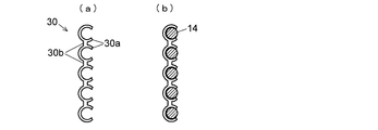
- FIG. 3 is a plan view showing an example of such a tube holding member 30.
- the tube holding member 30 has a configuration in which a plurality of substantially C-shaped clamp portions 30a each capable of holding a single deaeration tube are connected by a connecting portion 30b.
- a tube holding member 30 When such a tube holding member 30 is used, even in a portion where a plurality of deaeration tubes are held by the tube holding member 30, adjacent deaeration tubes do not completely adhere to each other, and a certain space is secured therebetween. In the portion where the adjacent deaeration tubes are in close contact with each other in the loop-shaped portion 14c, the gas is difficult to escape from the tube, which is disadvantageous in terms of deaeration efficiency.
Landscapes
- Chemical & Material Sciences (AREA)
- Chemical Kinetics & Catalysis (AREA)
- Engineering & Computer Science (AREA)
- Water Supply & Treatment (AREA)
- Degasification And Air Bubble Elimination (AREA)
- Separation Using Semi-Permeable Membranes (AREA)
Abstract
L'invention concerne un dispositif de dégazage du type sous vide qui utilise une membrane de séparation gaz-liquide, les deux parties d'extrémité d'un tube de dégazage (14) disposé à l'intérieur d'une chambre à vide étant raccordées à des parties de raccordement de trajet d'écoulement (12, 13) disposées dans une partie couvercle de la chambre (11), le tube étant logé à l'intérieur de la chambre à vide alors qu'il est enroulé sous la forme d'une boucle. Au niveau de trois emplacements dans la partie en forme de boucle (14c) du tube de dégazage (14), de multiples tubes de dégazage (14) sont liés et joints par une bande de résine fluorée qui est plus molle que le matériau perméable aux gaz constituant les tubes. Ainsi, même lorsque des fluctuations surviennent dans un écoulement de phase mobile à l'intérieur du tube de dégazage (14) ou lorsque l'écoulement devient intermittent, des ondulations dans le tube de dégazage (14) ne se produisent pas facilement et le frottement entre les tubes est empêché même si des ondulations se produisent. Par conséquent, il est possible d'empêcher le tube de dégazage (14) de s'amincir à cause de l'abrasion, et des apparitions de fissures, qui provoquent une fuite de liquide, peuvent être évitées.
Priority Applications (1)
| Application Number | Priority Date | Filing Date | Title |
|---|---|---|---|
| PCT/JP2014/069938 WO2016016946A1 (fr) | 2014-07-29 | 2014-07-29 | Dispositif de dégazage |
Applications Claiming Priority (1)
| Application Number | Priority Date | Filing Date | Title |
|---|---|---|---|
| PCT/JP2014/069938 WO2016016946A1 (fr) | 2014-07-29 | 2014-07-29 | Dispositif de dégazage |
Publications (1)
| Publication Number | Publication Date |
|---|---|
| WO2016016946A1 true WO2016016946A1 (fr) | 2016-02-04 |
Family
ID=55216892
Family Applications (1)
| Application Number | Title | Priority Date | Filing Date |
|---|---|---|---|
| PCT/JP2014/069938 Ceased WO2016016946A1 (fr) | 2014-07-29 | 2014-07-29 | Dispositif de dégazage |
Country Status (1)
| Country | Link |
|---|---|
| WO (1) | WO2016016946A1 (fr) |
Cited By (2)
| Publication number | Priority date | Publication date | Assignee | Title |
|---|---|---|---|---|
| US20200217869A1 (en) * | 2017-01-05 | 2020-07-09 | Illumina, Inc. | Flow cell liquid degassing system and method |
| WO2024004829A1 (fr) * | 2022-06-27 | 2024-01-04 | Dic株式会社 | Désaérateur |
Citations (5)
| Publication number | Priority date | Publication date | Assignee | Title |
|---|---|---|---|---|
| JPS54123785A (en) * | 1978-02-24 | 1979-09-26 | Du Pont | Deaerator |
| JPS6227703U (fr) * | 1985-07-31 | 1987-02-19 | ||
| JPH03157105A (ja) * | 1989-11-16 | 1991-07-05 | Chisso Corp | 液体脱気装置用気体透過部材及びその製造方法 |
| JP2003047803A (ja) * | 2001-07-10 | 2003-02-18 | Systec Inc | 脱気および脈動減少装置の応用例におけるバードイン配管 |
| WO2008035714A1 (fr) * | 2006-09-22 | 2008-03-27 | Nitto Denko Corporation | Dispositif de dégazage |
-
2014
- 2014-07-29 WO PCT/JP2014/069938 patent/WO2016016946A1/fr not_active Ceased
Patent Citations (5)
| Publication number | Priority date | Publication date | Assignee | Title |
|---|---|---|---|---|
| JPS54123785A (en) * | 1978-02-24 | 1979-09-26 | Du Pont | Deaerator |
| JPS6227703U (fr) * | 1985-07-31 | 1987-02-19 | ||
| JPH03157105A (ja) * | 1989-11-16 | 1991-07-05 | Chisso Corp | 液体脱気装置用気体透過部材及びその製造方法 |
| JP2003047803A (ja) * | 2001-07-10 | 2003-02-18 | Systec Inc | 脱気および脈動減少装置の応用例におけるバードイン配管 |
| WO2008035714A1 (fr) * | 2006-09-22 | 2008-03-27 | Nitto Denko Corporation | Dispositif de dégazage |
Cited By (3)
| Publication number | Priority date | Publication date | Assignee | Title |
|---|---|---|---|---|
| US20200217869A1 (en) * | 2017-01-05 | 2020-07-09 | Illumina, Inc. | Flow cell liquid degassing system and method |
| WO2024004829A1 (fr) * | 2022-06-27 | 2024-01-04 | Dic株式会社 | Désaérateur |
| JPWO2024004829A1 (fr) * | 2022-06-27 | 2024-01-04 |
Similar Documents
| Publication | Publication Date | Title |
|---|---|---|
| US8177889B2 (en) | Gas removal device | |
| Erans et al. | Calcium looping sorbents for CO2 capture | |
| US8784630B2 (en) | Sample stacking method using on-line automatic solid phase extraction coupled to nonaqueous capillary electrophoresis and interface structure between solid-phase preconcentration cartridge and capillary therefor | |
| WO2016016946A1 (fr) | Dispositif de dégazage | |
| KR101486192B1 (ko) | 기밀성과 정렬성능 향상한 플랜지 배관 연결용 가스켓 | |
| FR2965888B1 (fr) | Canalisation d'evacuation de gaz et procede d'evacuation associe | |
| RU2012155154A (ru) | Трубный зажим с присоединительным элементом | |
| CN104781665A (zh) | 配管连结接头 | |
| KR101270316B1 (ko) | 탈기 장치 | |
| US9061247B2 (en) | Separation membrane module | |
| BRPI0816978A2 (pt) | Processo de tratamento do volume de informações manipulado durante uma fase de depuração de um software de funcionamento de um sistema embarcado a bordo de uma aeronave, e dispositivo de utilização. | |
| EP2557409B1 (fr) | Ensemble de cartouche et pince de cartouche, pince de cartouche à utiliser dans un tel ensemble et cartouche à utiliser dans un tel ensemble | |
| RU2009135002A (ru) | Пробирка для упаковки заданного объема биологической субстанции с низкой температурой хранения и содержащая ее система | |
| JP6334575B2 (ja) | フレキシブルな容器とこの種のフレキシブルな容器用の充填装置及びそれに応じた充填方法 | |
| KR20210021401A (ko) | 의약품 또는 생물학적 매체를 저장하는 시스템 및 방법 | |
| CN102294064A (zh) | 自排气药液过滤器覆盖固定疏水排气膜的方法 | |
| JP6333986B2 (ja) | 化学溶液収容瓶及びその製造方法 | |
| EA201170111A1 (ru) | Система и способ для наполнения контейнеров складного типа | |
| US20150377390A1 (en) | Piping component and pipe | |
| JP6646499B2 (ja) | 脱気装置 | |
| CN201934765U (zh) | 一种多层金属膜片敏感装置 | |
| JP2019506339A (ja) | 二つの柔軟性を有するチューブ状容器を接続する方法 | |
| JPWO2017033914A1 (ja) | 液体クロマトグラフィー用カラム及びそれを備えた液体クロマトグラフ装置 | |
| JP6881474B2 (ja) | 分析装置用の配管デバイス及びその配管デバイスを用いた分析装置 | |
| JP2008196868A (ja) | 汚染防止輸液チューブ |
Legal Events
| Date | Code | Title | Description |
|---|---|---|---|
| 121 | Ep: the epo has been informed by wipo that ep was designated in this application |
Ref document number: 14898880 Country of ref document: EP Kind code of ref document: A1 |
|
| NENP | Non-entry into the national phase |
Ref country code: DE |
|
| NENP | Non-entry into the national phase |
Ref country code: JP |
|
| 122 | Ep: pct application non-entry in european phase |
Ref document number: 14898880 Country of ref document: EP Kind code of ref document: A1 |