WO2016016990A1 - Dispositif axial et véhicule de travail - Google Patents
Dispositif axial et véhicule de travail Download PDFInfo
- Publication number
- WO2016016990A1 WO2016016990A1 PCT/JP2014/070183 JP2014070183W WO2016016990A1 WO 2016016990 A1 WO2016016990 A1 WO 2016016990A1 JP 2014070183 W JP2014070183 W JP 2014070183W WO 2016016990 A1 WO2016016990 A1 WO 2016016990A1
- Authority
- WO
- WIPO (PCT)
- Prior art keywords
- axial direction
- spline
- housing
- axle
- bearing member
- Prior art date
- Legal status (The legal status is an assumption and is not a legal conclusion. Google has not performed a legal analysis and makes no representation as to the accuracy of the status listed.)
- Ceased
Links
Images




Classifications
-
- B—PERFORMING OPERATIONS; TRANSPORTING
- B60—VEHICLES IN GENERAL
- B60B—VEHICLE WHEELS; CASTORS; AXLES FOR WHEELS OR CASTORS; INCREASING WHEEL ADHESION
- B60B35/00—Axle units; Parts thereof ; Arrangements for lubrication of axles
- B60B35/12—Torque-transmitting axles
- B60B35/18—Arrangement of bearings
-
- B—PERFORMING OPERATIONS; TRANSPORTING
- B60—VEHICLES IN GENERAL
- B60K—ARRANGEMENT OR MOUNTING OF PROPULSION UNITS OR OF TRANSMISSIONS IN VEHICLES; ARRANGEMENT OR MOUNTING OF PLURAL DIVERSE PRIME-MOVERS IN VEHICLES; AUXILIARY DRIVES FOR VEHICLES; INSTRUMENTATION OR DASHBOARDS FOR VEHICLES; ARRANGEMENTS IN CONNECTION WITH COOLING, AIR INTAKE, GAS EXHAUST OR FUEL SUPPLY OF PROPULSION UNITS IN VEHICLES
- B60K17/00—Arrangement or mounting of transmissions in vehicles
- B60K17/04—Arrangement or mounting of transmissions in vehicles characterised by arrangement, location or kind of gearing
-
- B—PERFORMING OPERATIONS; TRANSPORTING
- B60—VEHICLES IN GENERAL
- B60K—ARRANGEMENT OR MOUNTING OF PROPULSION UNITS OR OF TRANSMISSIONS IN VEHICLES; ARRANGEMENT OR MOUNTING OF PLURAL DIVERSE PRIME-MOVERS IN VEHICLES; AUXILIARY DRIVES FOR VEHICLES; INSTRUMENTATION OR DASHBOARDS FOR VEHICLES; ARRANGEMENTS IN CONNECTION WITH COOLING, AIR INTAKE, GAS EXHAUST OR FUEL SUPPLY OF PROPULSION UNITS IN VEHICLES
- B60K17/00—Arrangement or mounting of transmissions in vehicles
- B60K17/30—Arrangement or mounting of transmissions in vehicles the ultimate propulsive elements, e.g. ground wheels, being steerable
-
- F—MECHANICAL ENGINEERING; LIGHTING; HEATING; WEAPONS; BLASTING
- F16—ENGINEERING ELEMENTS AND UNITS; GENERAL MEASURES FOR PRODUCING AND MAINTAINING EFFECTIVE FUNCTIONING OF MACHINES OR INSTALLATIONS; THERMAL INSULATION IN GENERAL
- F16D—COUPLINGS FOR TRANSMITTING ROTATION; CLUTCHES; BRAKES
- F16D1/00—Couplings for rigidly connecting two coaxial shafts or other movable machine elements
- F16D1/06—Couplings for rigidly connecting two coaxial shafts or other movable machine elements for attachment of a member on a shaft or on a shaft-end
-
- F—MECHANICAL ENGINEERING; LIGHTING; HEATING; WEAPONS; BLASTING
- F16—ENGINEERING ELEMENTS AND UNITS; GENERAL MEASURES FOR PRODUCING AND MAINTAINING EFFECTIVE FUNCTIONING OF MACHINES OR INSTALLATIONS; THERMAL INSULATION IN GENERAL
- F16H—GEARING
- F16H1/00—Toothed gearings for conveying rotary motion
- F16H1/28—Toothed gearings for conveying rotary motion with gears having orbital motion
- F16H1/32—Toothed gearings for conveying rotary motion with gears having orbital motion in which the central axis of the gearing lies inside the periphery of an orbital gear
Definitions
- the present invention relates to an axle device and a work vehicle.
- axle devices such as wheel loaders and backhoe loaders are equipped with axle devices.
- the axle device is configured to transmit driving force from the engine to the wheels.
- the axle device includes a housing, a first axle shaft, a planetary gear mechanism, and a second axle shaft.
- the housing is fixed to the body frame.
- the planetary gear mechanism decelerates the rotation of the first axle shaft and transmits it to the second axle shaft.
- the second axle shaft supports the wheels.
- a restriction disc is attached to the inner end of the second axle shaft in the axial direction. The restriction disc restricts the movement of the second axle shaft outward in the axial direction.
- the size of the restriction disk is increased to improve the strength of the restriction disk.
- increasing the size of the regulation disk or the like causes a problem of increasing the size of the axle device.
- An object of the present invention is to improve the wheel holding force without increasing the size of the axle device.
- the axle device includes a housing, a first axle shaft, a planetary gear mechanism, a second axle shaft, a bearing member, and a regulating member.
- the first axle shaft extends in the axial direction.
- the planetary gear mechanism includes a sun gear, a planetary gear, a carrier, and a ring gear.
- the sun gear rotates integrally with the first axle shaft.
- Planetary gear meshes with sun gear.
- the carrier has a through hole including a first spline portion.
- the carrier rotatably supports the planetary gear.
- the ring gear is fixed to the housing and meshes with the planetary gear.
- the planetary gear mechanism is accommodated in the housing.
- the second Askle shaft has a shaft main body portion, a tip portion, and a groove portion.
- the shaft main body has a second spline portion that engages with the first spline portion.
- the shaft main body extends in the axial direction within the housing.
- the tip portion protrudes axially outward from the housing.
- the groove portion extends in the circumferential direction at the second spline portion.
- the bearing member is supported by the housing.
- the bearing member rotatably supports the second axle shaft.
- the restricting member is disposed in the groove portion.
- the restricting member protrudes radially outward from the groove.
- the second spline part has an engaging part that engages with the first spline part.
- the restricting member is disposed outside the engaging portion in the axial direction.
- the restricting member is disposed on the inner side in the axial direction than the bearing member.
- the restricting member protrudes radially outward from the groove. For this reason, even if the second axle shaft moves to the outside in the axial direction, the regulating member comes into contact with the bearing member, and the movement of the second axle shaft to the outside in the axial direction is regulated. Therefore, the holding force of the wheel can be improved without increasing the size of the axle device.
- the second spline portion has a spline end portion.
- the spline end portion is disposed at an outer end portion in the axial direction of the second spline portion.
- the diameter of the valley bottom increases toward the outside in the axial direction.
- the groove is formed at the end of the spline. According to this structure, even if a groove part is formed, it can suppress that the intensity
- the inner wall surface of the groove portion is constituted by a smooth surface. According to this configuration, it is possible to prevent stress concentration from occurring on the inner wall surface of the groove.
- the groove has a semicircular cross-sectional shape.
- the restricting member has an annular shape.
- the regulating member has a circular cross section.
- the housing has a protruding portion protruding radially inward from the inner peripheral surface.
- the bearing member comes into contact with the protrusion from the inside in the axial direction. According to this configuration, the bearing member is restricted from moving outward in the axial direction by contacting the protruding portion.
- the axially inner end of the bearing member is chamfered. According to this configuration, when the bearing member and the regulating member come into contact with each other, the bearing member can press the regulating member radially inward by the chamfered inner peripheral side end. As a result, it is possible to prevent the restricting member from coming off the groove.
- the inner peripheral end portion on the inner side in the axial direction of the bearing member is R-chamfered.
- the second spline portion has a plurality of valleys and a plurality of peaks.
- a groove part is formed in each peak part.
- the axle device may further include at least one spacer between the bearing member and the regulating member.
- a work vehicle includes any one of the axle devices described above, a body frame, and wheels.
- An axle device is attached to the body frame.
- the wheel is attached to the tip of the second axle shaft.
- the holding power of the wheel can be improved without increasing the size of the axle device.
- FIG. 7 is a sectional view taken along line VII-VII in FIG. 6.
- the enlarged view of an axle apparatus which concerns on the modification 1.
- FIG. 1 is a side view of work vehicle 100.
- “right”, “left”, “upper”, and “lower” indicate directions based on a state of looking forward from the cab.
- “Vehicle width direction” is synonymous with “left-right direction”.
- the “front-rear direction” means the front-rear direction of the vehicle body.
- the work vehicle 100 includes a body frame 101, a work implement 102, a plurality of wheels 103, and a cab 104.
- the cab 104 is placed on the vehicle body frame 101.
- the work machine 102 is attached to the front portion of the vehicle body frame 101.
- the work machine 102 includes a boom 102a, a bucket 102b, a boom cylinder 102c, and a bucket cylinder 102d.
- the boom 102a is a member for lifting the bucket 102b.
- the boom 102a is attached to the vehicle body frame 101 so as to be rotatable in the vertical direction.
- the bucket 102b is attached to the tip of the boom 102a so as to be rotatable in the vertical direction.
- the boom 102a is rotated up and down by a boom cylinder 102c.
- Bucket 102b is rotated up and down by bucket cylinder 102d. Note that other work tools such as forks can be attached to the boom 102a instead of the bucket 102b.
- the work vehicle 100 includes an engine 105 and a hydraulic pump 106.
- the engine 105 is, for example, a diesel engine, and the driving force generated by the engine 105 is transmitted to the hydraulic pump 106.
- the driving force generated by the engine 105 is transmitted to the wheel 103 via the axle device 10 described later.
- the hydraulic pump 106 discharges hydraulic oil when driven by the engine 105.
- the cylinders 102c and 102d described above are driven by hydraulic oil discharged from the hydraulic pump 106.
- FIG. 2 is a cross-sectional view of the axle device 10 taken along the line II-II in FIG. As shown in FIG. 2, the axle device 10 is used in a work vehicle having a body frame 101.
- the axle device 10 includes a first axle shaft 1, a second axle shaft 2, a housing 3, a planetary gear mechanism 4, a first bearing member 5, and a regulating member 6.
- the axle device 10 further includes a brake mechanism 7 and a second bearing member 8.
- the housing 3 is configured to be fixed to the vehicle body frame 101. Specifically, the housing 3 has a mounting portion 30. The housing 3 is attached to the vehicle body frame 101 with bolts or the like via the attachment portion 30.
- the housing 3 houses the first axle shaft 1, the second axle shaft 2, and the planetary gear mechanism 4.
- the housing 3 extends in the axial direction.
- the housing 3 opens to the outside in the axial direction.
- the axial direction is a direction in which the central axis of the first axle shaft 1 extends. In a state where the axle device 10 is attached to the vehicle body frame 101, the axial direction extends parallel to the vehicle width direction.
- the outside in the axial direction means the side far from the center of the vehicle body in the axial direction.
- the inner side in the axial direction means the side close to the center of the vehicle body in the axial direction.
- the housing 3 is divided into a plurality of parts. Specifically, the housing 3 includes a housing main body portion 31 and a housing end portion 32.
- the housing body 31 houses the first axle shaft 1 and the brake mechanism 7.
- the housing end 32 is detachably attached to the housing main body 31.
- the housing end 32 is attached to the housing main body 31 using a bolt.
- the housing end portion 32 accommodates the second axle shaft 2 and the planetary gear mechanism 4.
- the housing 3 supports the first bearing member 5. Specifically, the movement of the first bearing member 5 in the radial direction is restricted by the inner peripheral surface of the housing 3.
- the housing 3 has a protruding portion 33.
- the protruding portion 33 protrudes radially inward from the inner peripheral surface of the housing 3.
- the protrusion 33 is an annular shape extending in the circumferential direction.
- the first bearing member 5 comes into contact with the protruding portion 33 from the inner side in the axial direction.
- the first bearing member 5 is restricted from moving outward in the axial direction by coming into contact with the protruding portion 33.
- the radial direction means the radial direction of a circle centered on the central axis of the first axle shaft 1.
- the first axle shaft 1 extends in the axial direction.
- the first axle shaft 1 is rotationally driven by a driving force from the engine 105.
- the first axle shaft 1 is transmitted with a driving force from the engine 105 via a differential mechanism (not shown).
- the first axle shaft 1 rotates around an axis extending in the axial direction.
- An escape portion 12 is formed at the axially outer end of the first axle shaft 1 (see FIG. 3).
- FIG. 3 is an enlarged view of the axle device 10.
- the planetary gear mechanism 4 includes a sun gear 41, a plurality of planetary gears 42, a carrier 43, and a ring gear 44.
- the planetary gear mechanism 4 is configured to reduce the rotation of the first axle shaft 1 and transmit it to the second axle shaft 2.
- the sun gear 41 rotates integrally with the first axle shaft 1. Specifically, the sun gear 41 is formed on the outer peripheral surface of the first axle shaft 1. The sun gear 41 is formed at the axially outer end of the first axle shaft 1. The sun gear 41 is a separate member from the first axle shaft 1 and may be fixed to the first axle shaft 1.
- Each planetary gear 42 meshes with the sun gear 41.
- Each planetary gear 42 is disposed around the sun gear 41.
- Each planetary gear 42 is arranged at intervals in the circumferential direction.
- the circumferential direction refers to the circumferential direction of a circle centered on the central axis of the first axle shaft 1.
- Each planetary gear 42 is arranged to be able to rotate.
- Each planetary gear 42 is arranged so as to be capable of revolving around the sun gear 41.
- the carrier 43 supports each planetary gear 42 rotatably.
- the carrier 43 rotates with the revolution of each planetary gear 42. That is, the carrier 43 can rotate around the central axis of the first axle shaft 1.
- Each planetary gear 42 can rotate while being supported by the carrier 43, and can revolve around the sun gear 41.
- the carrier 43 is in contact with the first bearing member 5 in the axial direction. Specifically, the end portion 431 on the outer side in the axial direction of the carrier 43 is in contact with the first bearing member 5. This restricts the carrier 43 from moving outward in the axial direction. The carrier 43 is in contact with the inner ring of the first bearing member 5.
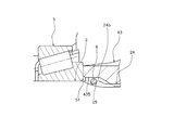
- FIG. 4 is an enlarged view showing a part of the axle device 10.
- the carrier 43 has a through hole 432.
- the second axle shaft 2 extends through the through hole 432.
- the through hole 432 has a first spline part 433.
- a first spline portion 433 is formed on the inner wall surface of the through hole 432.
- a shoulder portion 434 is formed at the inner end portion in the axial direction of the through hole 432.
- the axially inner end portion of the through hole 432 has a larger radius than other portions of the through hole 432.
- the ring gear 44 meshes with each planetary gear 42.
- the ring gear 44 is fixed to the housing 3.
- the ring gear 44 is fixed to the housing end 32.
- the ring gear 44 may be formed directly on the inner peripheral surface of the housing 3.
- the second axle shaft 2 extends in the axial direction. Specifically, the central axis of the second axle shaft 2 and the central axis of the first axle shaft 1 are arranged on substantially the same straight line.
- the second axle shaft 2 has a shaft main body portion 21 and a tip portion 22.
- the shaft main body portion 21 and the tip end portion 22 are formed of a single member.
- the shaft main body 21 extends in the axial direction in the housing 3.
- the shaft main body 21 is rotatably supported by the housing 3. Specifically, the shaft body 21 is supported by the housing 3 via the first bearing member 5 and the second bearing member 8.
- the shaft main body 21 has a second spline portion 24.
- the second spline part 24 is engaged with the first spline part 433 of the carrier 43.
- a part of the second spline part 24 is not engaged with the first spline part 433.
- a portion of the second spline portion 24 that engages with the first spline portion 433 is referred to as an engagement portion 24a.
- the second spline portion 24 has a spline end portion 24b.
- the spline end portion 24 b is disposed at the axially outer end portion of the second spline portion 24.
- the spline end portion 24 b is not engaged with the first spline portion 433.
- the radius of the valley bottom increases toward the outside in the axial direction.
- the second spline part 24 has a plurality of valleys and a plurality of peaks.
- the valleys and the peaks are alternately arranged in the circumferential direction.
- Each trough and each peak extend in the axial direction.
- the radius of the valley bottom of each valley portion gradually increases toward the outside in the axial direction.
- the outer diameter of each peak part in the spline end part 24b is larger than the outer diameter of each peak part in the 2nd spline part 24 other than the spline end part 24b.
- the second spline portion 24 is formed by forming a plurality of valleys with a disc-shaped cutter 240.
- the cutter 240 forms a trough in the shaft body 21 while moving from the axially inner side toward the axially outer side.
- each valley at the axially outer end of the second spline part 24 has a shape along the outer peripheral edge of the cutter 240. That is, the radius of the valley bottom of each valley portion at the axially outer end portion of the second spline portion 24 gradually increases toward the outside in the axial direction. This axially outer end is the spline end 24b.
- FIG. 5 is an enlarged view showing a part of the second axle shaft 2.
- the second axle shaft 2 further has a groove 25.
- the groove part 25 is formed in the second spline part 24.
- the groove part 25 is arrange
- the groove portion 25 is formed in the spline end portion 24b.
- the groove portion 25 is formed in each peak portion of the second spline portion 24.
- the groove portion 25 extends in the circumferential direction of the shaft main body portion 21.
- the groove part 25 is a circumferential groove part.
- the inner wall surface of the groove part 25 is comprised from a smooth surface. That is, the corner of the inner wall surface of the groove 25 is formed in an arc shape.
- the groove part 25 has a semicircular cross-sectional shape.
- the cross section of the groove part 25 shows the cross section which cut
- the semicircular shape does not mean only a complete semicircular shape, but a concept including a substantial semicircular shape.
- the tip 22 protrudes from the housing 3.
- the front end portion 22 is configured so that the rear wheel 103 is attached.
- the rear wheel 103 is attached to the distal end portion 22 using a bolt or the like.
- the outer shape of the tip 22 is circular.
- the tip portion 22 has a disk shape.
- the tip 22 has a larger diameter than the shaft body 21.
- the second axle shaft 2 is restricted from moving outward in the axial direction.
- a regulation disk 9 is attached to the second axle shaft 2.
- the regulation disc 9 is attached to the second axle shaft 2 by a bolt 90.
- the restriction disc 9 is configured to restrict the movement of the second axle shaft 2 outward in the axial direction.
- the regulation disc 9 has a protruding portion 91.
- the protruding portion 91 protrudes in the radial direction from the axially inner end portion 23 of the second axle shaft 2.
- the restriction disk 9 is disk-shaped, and the outer diameter of the restriction disk 9 is larger than the outer diameter of the axially inner end 23 of the second axle shaft 2.
- the protruding portion 91 of the restriction disc 9 abuts on the shoulder portion 434 of the carrier 43 in the axial direction.
- the regulating member 6 is disposed in the groove portion 25 of the second axle shaft 2. That is, the restricting member 6 is disposed on the outer side in the axial direction than the engaging portion 24a, and is disposed on the inner side in the axial direction with respect to the first bearing member 5.
- the restricting member 6 protrudes radially outward from the groove 25 in a state where it is disposed in the groove 25.
- the inner peripheral side portion of the restricting member 6 is fitted into the groove portion 25, and the outer peripheral side portion of the restricting member 6 protrudes from the groove portion 25.
- the regulating member 6 has an outer diameter D that is larger than the inner diameter of the first bearing member 5 (see FIG. 6).
- the carrier 43 has an escape portion 435 in order to avoid interference with the regulating member 6.
- FIG. 6 is a view of the regulating member 6 viewed along the axial direction. As shown in FIG. 6, the regulating member 6 is formed in a C shape.
- the regulating member 6 is made of, for example, a piano wire, a hard net wire, a spring steel wire, or the like.
- the outer diameter D of the regulating member 6 is larger than the inner diameter of the first bearing member 5.
- the restricting member 6 is, for example, a retaining ring.
- FIG. 7 is a cross-sectional view taken along line VII-VII in FIG.
- the cross-sectional shape of the regulating member 6 is a circular shape having a diameter d. That is, the regulating member 6 is formed by curving a rod-like member having a circular cross section.
- the radius of the arc of the groove 25 is equal to or less than the radius d / 2 of the cross section of the restricting member 6.
- the first bearing member 5 is supported by the housing 3. Moreover, the 1st bearing member 5 is supporting the 2nd axle shaft 2 rotatably. Specifically, the first bearing member 5 is disposed between the housing 3 and the second axle shaft 2 in the radial direction. The first bearing member 5 is attached to the outer peripheral surface of the shaft main body 21 of the second axle shaft 2. The first bearing member 5 is located on the outer side in the axial direction than the second spline portion 24.
- the first bearing member 5 is supported by the housing 3 so as to be restricted from moving outward in the axial direction. Specifically, as described above, when the first bearing member 5 abuts on the protruding portion 33 of the housing 3, the first bearing member 5 is restricted from moving outward in the axial direction.
- the first bearing member 5 corresponds to the bearing member of the present invention.
- the inner peripheral end 51 on the inner side in the axial direction of the first bearing member 5 is chamfered.
- the inner peripheral end 51 of the first bearing member 5 is R-chamfered.
- the inner peripheral end 51 is R-chamfered, it faces inward in the radial direction.
- the inner peripheral end of the first bearing member 5 The part 51 presses the regulating member 6 toward the radially inner side. Therefore, it is possible to reliably prevent the restricting member 6 from being detached from the groove portion 25.
- the inner peripheral end portion 51 of which the first bearing member 5 is chamfered is configured to come into contact with the regulating member 6.
- the second bearing member 8 is supported by the housing 3. Moreover, the 2nd bearing member 8 is supporting the 2nd axle shaft 2 rotatably. Specifically, the second bearing member 8 is disposed between the housing 3 and the second axle shaft 2 in the radial direction. The second bearing member 8 is attached to the outer peripheral surface of the shaft main body 21 of the second axle shaft 2. The second bearing member 8 is located on the outer side in the axial direction than the first bearing member 5.
- the brake mechanism 7 is configured to brake the rotation of the rear wheel 103.
- the brake mechanism 7 is a multi-plate brake mechanism. Specifically, the brake mechanism 7 includes a plurality of rotating disks 71, a plurality of fixed disks 72, and a piston 73.
- Each rotating disk 71 rotates integrally with the first axle shaft 1. Specifically, each rotating disk 71 has a through hole in the center. The first axle shaft 1 passes through the through hole of each rotary disk 71. Each rotating disk 71 is spline-engaged with the first axle shaft 1. Each rotary disk 71 is slidable in the axial direction.
- Each fixed disk 72 is spline-engaged with the housing 3. That is, each fixed disk 72 does not rotate. Each fixed disk 72 is slidable in the axial direction.
- the restricting member 6 protrudes radially outward from the groove portion 25.
- the outer diameter D of the restricting member 6 is larger than the inner diameter of the first bearing member 5.
- a spacer 11 may be disposed between the first bearing member 5 and the regulating member 6.
- the protrusion part 33 was cyclic
- the housing 3 has a plurality of protrusions 33, and the protrusions 33 may be arranged along the circumferential direction at intervals.
- Modification 4 in the said embodiment, although the wheel loader was illustrated as a working vehicle, the working vehicle to which this invention is applied is not limited to a wheel loader.
- the axle device according to the present invention can be applied to other work vehicles such as a backhoe loader.
- the groove part 25 is continuously extended in the circumferential direction
- the shape of the groove part 25 is not specifically limited to this.
- the groove part 25 may extend intermittently in the circumferential direction.
- the wheel loader 100 has a plurality of regulating members 9. Each regulating member 9 is arranged in each groove 25.
- control member 9 is annular
- shape of the control member 9 is not specifically limited to this.
- restriction member 9 may be a rectangular ring.
Landscapes
- Engineering & Computer Science (AREA)
- Mechanical Engineering (AREA)
- General Engineering & Computer Science (AREA)
- Chemical & Material Sciences (AREA)
- Combustion & Propulsion (AREA)
- Transportation (AREA)
- Retarders (AREA)
Abstract
Dispositif d'essieu (10) pourvu d'un boîtier (3), d'un premier arbre d'essieu (1), d'un mécanisme de satellite (4), d'un second arbre d'essieu (2), d'un premier élément de palier (5) et d'un élément de régulation (6). Un porteur (43) du mécanisme de satellite (4) possède un trou traversant (432) comprenant une première section cannelure (433). Une section corps d'arbre (21) du second arbre d'essieu (2) comporte une seconde section cannelure (24) en prise avec la première section cannelure (433). Un évidement (25) est formé dans la seconde section cannelure (24). Le premier élément de palier (5) est supporté par le boîtier (3). Le premier élément de palier (5) supporte en rotation le second arbre d'essieu (2). L'élément de régulation (6) est disposé dans l'évidement (25). L'élément de régulation (6) fait radialement saillie vers l'extérieur depuis l'évidement (25).
Priority Applications (1)
| Application Number | Priority Date | Filing Date | Title |
|---|---|---|---|
| PCT/JP2014/070183 WO2016016990A1 (fr) | 2014-07-31 | 2014-07-31 | Dispositif axial et véhicule de travail |
Applications Claiming Priority (1)
| Application Number | Priority Date | Filing Date | Title |
|---|---|---|---|
| PCT/JP2014/070183 WO2016016990A1 (fr) | 2014-07-31 | 2014-07-31 | Dispositif axial et véhicule de travail |
Publications (1)
| Publication Number | Publication Date |
|---|---|
| WO2016016990A1 true WO2016016990A1 (fr) | 2016-02-04 |
Family
ID=55216931
Family Applications (1)
| Application Number | Title | Priority Date | Filing Date |
|---|---|---|---|
| PCT/JP2014/070183 Ceased WO2016016990A1 (fr) | 2014-07-31 | 2014-07-31 | Dispositif axial et véhicule de travail |
Country Status (1)
| Country | Link |
|---|---|
| WO (1) | WO2016016990A1 (fr) |
Citations (4)
| Publication number | Priority date | Publication date | Assignee | Title |
|---|---|---|---|---|
| JPH041710U (fr) * | 1990-04-20 | 1992-01-08 | ||
| JPH0771568A (ja) * | 1993-06-29 | 1995-03-17 | Komatsu Ltd | 遊星ギヤ減速機の軸受固定装置 |
| JP2008247055A (ja) * | 2007-03-29 | 2008-10-16 | Komatsu Ltd | リダクション型アクスル装置 |
| JP2013127280A (ja) * | 2011-12-16 | 2013-06-27 | Toyota Motor Corp | 車両用デファレンシャル装置 |
-
2014
- 2014-07-31 WO PCT/JP2014/070183 patent/WO2016016990A1/fr not_active Ceased
Patent Citations (4)
| Publication number | Priority date | Publication date | Assignee | Title |
|---|---|---|---|---|
| JPH041710U (fr) * | 1990-04-20 | 1992-01-08 | ||
| JPH0771568A (ja) * | 1993-06-29 | 1995-03-17 | Komatsu Ltd | 遊星ギヤ減速機の軸受固定装置 |
| JP2008247055A (ja) * | 2007-03-29 | 2008-10-16 | Komatsu Ltd | リダクション型アクスル装置 |
| JP2013127280A (ja) * | 2011-12-16 | 2013-06-27 | Toyota Motor Corp | 車両用デファレンシャル装置 |
Non-Patent Citations (1)
| Title |
|---|
| KOROGARI JIKUUKE KOGAKU, 20 January 1978 (1978-01-20), pages 40 * |
Similar Documents
| Publication | Publication Date | Title |
|---|---|---|
| JP6453880B2 (ja) | 動力伝達装置 | |
| JP4985741B2 (ja) | 車両用動力伝達装置 | |
| WO2020095865A1 (fr) | Camion-benne | |
| EP3439907B1 (fr) | Porte-satellites et transmission à engrenages planétaires | |
| JP6340350B2 (ja) | 走行用アクスル装置 | |
| CN101115936A (zh) | 碟形弹簧 | |
| JP6729492B2 (ja) | 駆動装置 | |
| EP2843139B1 (fr) | Dispositif d'entraînement de machine de construction | |
| EP1763448B1 (fr) | Transmission satellite et dispositif d'entrainement comportant ladite transmission | |
| JP2015077830A (ja) | アクスル装置 | |
| JP6740726B2 (ja) | ハブ軸受 | |
| WO2016016990A1 (fr) | Dispositif axial et véhicule de travail | |
| JP6408425B2 (ja) | 動力伝達装置およびモータグレーダ | |
| KR100972214B1 (ko) | 건설장비 차량의 액슬 허브 감속 장치 | |
| EP1910121B1 (fr) | Transmission planetaire, dispositif d' entrainement comprenant la transmission planetaire et vehicule comprenant le dispositif d' entrainement | |
| JP2018114773A (ja) | 走行用アクスル装置 | |
| JP2015135004A (ja) | ホイール式建設機械 | |
| JP4890000B2 (ja) | アクスル装置および作業機械 | |
| JP5764157B2 (ja) | 作業車両のアクスル装置及び作業車両 | |
| JP6762256B2 (ja) | 動力伝達装置および建設機械 | |
| JP6182428B2 (ja) | 遊星歯車減速装置およびその製造方法 | |
| CN112638685A (zh) | 用于车辆的驱动轮的轮毂装置 | |
| US20160347170A1 (en) | Integrated Wheel and Planet Carrier | |
| JP2005170160A (ja) | アクスル装置 | |
| JP2011088460A (ja) | 作業車両 |
Legal Events
| Date | Code | Title | Description |
|---|---|---|---|
| 121 | Ep: the epo has been informed by wipo that ep was designated in this application |
Ref document number: 14898695 Country of ref document: EP Kind code of ref document: A1 |
|
| NENP | Non-entry into the national phase |
Ref country code: DE |
|
| NENP | Non-entry into the national phase |
Ref country code: JP |
|
| 122 | Ep: pct application non-entry in european phase |
Ref document number: 14898695 Country of ref document: EP Kind code of ref document: A1 |