WO2016017176A1 - 有機物質の熱分解方法 - Google Patents
有機物質の熱分解方法 Download PDFInfo
- Publication number
- WO2016017176A1 WO2016017176A1 PCT/JP2015/003844 JP2015003844W WO2016017176A1 WO 2016017176 A1 WO2016017176 A1 WO 2016017176A1 JP 2015003844 W JP2015003844 W JP 2015003844W WO 2016017176 A1 WO2016017176 A1 WO 2016017176A1
- Authority
- WO
- WIPO (PCT)
- Prior art keywords
- organic substance
- catalyst
- thermal decomposition
- organic
- gas
- Prior art date
- Legal status (The legal status is an assumption and is not a legal conclusion. Google has not performed a legal analysis and makes no representation as to the accuracy of the status listed.)
- Ceased
Links
Images


Classifications
-
- C—CHEMISTRY; METALLURGY
- C10—PETROLEUM, GAS OR COKE INDUSTRIES; TECHNICAL GASES CONTAINING CARBON MONOXIDE; FUELS; LUBRICANTS; PEAT
- C10G—CRACKING HYDROCARBON OILS; PRODUCTION OF LIQUID HYDROCARBON MIXTURES, e.g. BY DESTRUCTIVE HYDROGENATION, OLIGOMERISATION, POLYMERISATION; RECOVERY OF HYDROCARBON OILS FROM OIL-SHALE, OIL-SAND, OR GASES; REFINING MIXTURES MAINLY CONSISTING OF HYDROCARBONS; REFORMING OF NAPHTHA; MINERAL WAXES
- C10G1/00—Production of liquid hydrocarbon mixtures from oil-shale, oil-sand, or non-melting solid carbonaceous or similar materials, e.g. wood, coal
- C10G1/10—Production of liquid hydrocarbon mixtures from oil-shale, oil-sand, or non-melting solid carbonaceous or similar materials, e.g. wood, coal from rubber or rubber waste
-
- B—PERFORMING OPERATIONS; TRANSPORTING
- B01—PHYSICAL OR CHEMICAL PROCESSES OR APPARATUS IN GENERAL
- B01J—CHEMICAL OR PHYSICAL PROCESSES, e.g. CATALYSIS OR COLLOID CHEMISTRY; THEIR RELEVANT APPARATUS
- B01J23/00—Catalysts comprising metals or metal oxides or hydroxides, not provided for in group B01J21/00
- B01J23/70—Catalysts comprising metals or metal oxides or hydroxides, not provided for in group B01J21/00 of the iron group metals or copper
- B01J23/74—Iron group metals
- B01J23/745—Iron
-
- B—PERFORMING OPERATIONS; TRANSPORTING
- B09—DISPOSAL OF SOLID WASTE; RECLAMATION OF CONTAMINATED SOIL
- B09B—DISPOSAL OF SOLID WASTE NOT OTHERWISE PROVIDED FOR
- B09B3/00—Destroying solid waste or transforming solid waste into something useful or harmless
- B09B3/30—Destroying solid waste or transforming solid waste into something useful or harmless involving mechanical treatment
- B09B3/35—Shredding, crushing or cutting
-
- B—PERFORMING OPERATIONS; TRANSPORTING
- B09—DISPOSAL OF SOLID WASTE; RECLAMATION OF CONTAMINATED SOIL
- B09B—DISPOSAL OF SOLID WASTE NOT OTHERWISE PROVIDED FOR
- B09B3/00—Destroying solid waste or transforming solid waste into something useful or harmless
- B09B3/40—Destroying solid waste or transforming solid waste into something useful or harmless involving thermal treatment, e.g. evaporation
-
- C—CHEMISTRY; METALLURGY
- C02—TREATMENT OF WATER, WASTE WATER, SEWAGE, OR SLUDGE
- C02F—TREATMENT OF WATER, WASTE WATER, SEWAGE, OR SLUDGE
- C02F11/00—Treatment of sludge; Devices therefor
-
- C—CHEMISTRY; METALLURGY
- C02—TREATMENT OF WATER, WASTE WATER, SEWAGE, OR SLUDGE
- C02F—TREATMENT OF WATER, WASTE WATER, SEWAGE, OR SLUDGE
- C02F11/00—Treatment of sludge; Devices therefor
- C02F11/10—Treatment of sludge; Devices therefor by pyrolysis
-
- C—CHEMISTRY; METALLURGY
- C08—ORGANIC MACROMOLECULAR COMPOUNDS; THEIR PREPARATION OR CHEMICAL WORKING-UP; COMPOSITIONS BASED THEREON
- C08J—WORKING-UP; GENERAL PROCESSES OF COMPOUNDING; AFTER-TREATMENT NOT COVERED BY SUBCLASSES C08B, C08C, C08F, C08G or C08H
- C08J11/00—Recovery or working-up of waste materials
- C08J11/04—Recovery or working-up of waste materials of polymers
- C08J11/10—Recovery or working-up of waste materials of polymers by chemically breaking down the molecular chains of polymers or breaking of crosslinks, e.g. devulcanisation
- C08J11/16—Recovery or working-up of waste materials of polymers by chemically breaking down the molecular chains of polymers or breaking of crosslinks, e.g. devulcanisation by treatment with inorganic material
-
- C—CHEMISTRY; METALLURGY
- C10—PETROLEUM, GAS OR COKE INDUSTRIES; TECHNICAL GASES CONTAINING CARBON MONOXIDE; FUELS; LUBRICANTS; PEAT
- C10G—CRACKING HYDROCARBON OILS; PRODUCTION OF LIQUID HYDROCARBON MIXTURES, e.g. BY DESTRUCTIVE HYDROGENATION, OLIGOMERISATION, POLYMERISATION; RECOVERY OF HYDROCARBON OILS FROM OIL-SHALE, OIL-SAND, OR GASES; REFINING MIXTURES MAINLY CONSISTING OF HYDROCARBONS; REFORMING OF NAPHTHA; MINERAL WAXES
- C10G1/00—Production of liquid hydrocarbon mixtures from oil-shale, oil-sand, or non-melting solid carbonaceous or similar materials, e.g. wood, coal
- C10G1/08—Production of liquid hydrocarbon mixtures from oil-shale, oil-sand, or non-melting solid carbonaceous or similar materials, e.g. wood, coal with moving catalysts
-
- C—CHEMISTRY; METALLURGY
- C10—PETROLEUM, GAS OR COKE INDUSTRIES; TECHNICAL GASES CONTAINING CARBON MONOXIDE; FUELS; LUBRICANTS; PEAT
- C10J—PRODUCTION OF PRODUCER GAS, WATER-GAS, SYNTHESIS GAS FROM SOLID CARBONACEOUS MATERIAL, OR MIXTURES CONTAINING THESE GASES; CARBURETTING AIR OR OTHER GASES
- C10J3/00—Production of combustible gases containing carbon monoxide from solid carbonaceous fuels
- C10J3/46—Gasification of granular or pulverulent flues in suspension
- C10J3/463—Gasification of granular or pulverulent flues in suspension in stationary fluidised beds
-
- C—CHEMISTRY; METALLURGY
- C10—PETROLEUM, GAS OR COKE INDUSTRIES; TECHNICAL GASES CONTAINING CARBON MONOXIDE; FUELS; LUBRICANTS; PEAT
- C10J—PRODUCTION OF PRODUCER GAS, WATER-GAS, SYNTHESIS GAS FROM SOLID CARBONACEOUS MATERIAL, OR MIXTURES CONTAINING THESE GASES; CARBURETTING AIR OR OTHER GASES
- C10J3/00—Production of combustible gases containing carbon monoxide from solid carbonaceous fuels
- C10J3/46—Gasification of granular or pulverulent flues in suspension
- C10J3/48—Apparatus; Plants
- C10J3/482—Gasifiers with stationary fluidised bed
-
- C—CHEMISTRY; METALLURGY
- C10—PETROLEUM, GAS OR COKE INDUSTRIES; TECHNICAL GASES CONTAINING CARBON MONOXIDE; FUELS; LUBRICANTS; PEAT
- C10J—PRODUCTION OF PRODUCER GAS, WATER-GAS, SYNTHESIS GAS FROM SOLID CARBONACEOUS MATERIAL, OR MIXTURES CONTAINING THESE GASES; CARBURETTING AIR OR OTHER GASES
- C10J2200/00—Details of gasification apparatus
- C10J2200/33—Laboratory scale gasifiers
-
- C—CHEMISTRY; METALLURGY
- C10—PETROLEUM, GAS OR COKE INDUSTRIES; TECHNICAL GASES CONTAINING CARBON MONOXIDE; FUELS; LUBRICANTS; PEAT
- C10J—PRODUCTION OF PRODUCER GAS, WATER-GAS, SYNTHESIS GAS FROM SOLID CARBONACEOUS MATERIAL, OR MIXTURES CONTAINING THESE GASES; CARBURETTING AIR OR OTHER GASES
- C10J2300/00—Details of gasification processes
- C10J2300/09—Details of the feed, e.g. feeding of spent catalyst, inert gas or halogens
- C10J2300/0903—Feed preparation
- C10J2300/0906—Physical processes, e.g. shredding, comminuting, chopping, sorting
-
- C—CHEMISTRY; METALLURGY
- C10—PETROLEUM, GAS OR COKE INDUSTRIES; TECHNICAL GASES CONTAINING CARBON MONOXIDE; FUELS; LUBRICANTS; PEAT
- C10J—PRODUCTION OF PRODUCER GAS, WATER-GAS, SYNTHESIS GAS FROM SOLID CARBONACEOUS MATERIAL, OR MIXTURES CONTAINING THESE GASES; CARBURETTING AIR OR OTHER GASES
- C10J2300/00—Details of gasification processes
- C10J2300/09—Details of the feed, e.g. feeding of spent catalyst, inert gas or halogens
- C10J2300/0913—Carbonaceous raw material
- C10J2300/0946—Waste, e.g. MSW, tires, glass, tar sand, peat, paper, lignite, oil shale
-
- C—CHEMISTRY; METALLURGY
- C10—PETROLEUM, GAS OR COKE INDUSTRIES; TECHNICAL GASES CONTAINING CARBON MONOXIDE; FUELS; LUBRICANTS; PEAT
- C10J—PRODUCTION OF PRODUCER GAS, WATER-GAS, SYNTHESIS GAS FROM SOLID CARBONACEOUS MATERIAL, OR MIXTURES CONTAINING THESE GASES; CARBURETTING AIR OR OTHER GASES
- C10J2300/00—Details of gasification processes
- C10J2300/09—Details of the feed, e.g. feeding of spent catalyst, inert gas or halogens
- C10J2300/0983—Additives
- C10J2300/0986—Catalysts
-
- C—CHEMISTRY; METALLURGY
- C10—PETROLEUM, GAS OR COKE INDUSTRIES; TECHNICAL GASES CONTAINING CARBON MONOXIDE; FUELS; LUBRICANTS; PEAT
- C10J—PRODUCTION OF PRODUCER GAS, WATER-GAS, SYNTHESIS GAS FROM SOLID CARBONACEOUS MATERIAL, OR MIXTURES CONTAINING THESE GASES; CARBURETTING AIR OR OTHER GASES
- C10J2300/00—Details of gasification processes
- C10J2300/09—Details of the feed, e.g. feeding of spent catalyst, inert gas or halogens
- C10J2300/0983—Additives
- C10J2300/0993—Inert particles, e.g. as heat exchange medium in a fluidized or moving bed, heat carriers, sand
-
- C—CHEMISTRY; METALLURGY
- C10—PETROLEUM, GAS OR COKE INDUSTRIES; TECHNICAL GASES CONTAINING CARBON MONOXIDE; FUELS; LUBRICANTS; PEAT
- C10J—PRODUCTION OF PRODUCER GAS, WATER-GAS, SYNTHESIS GAS FROM SOLID CARBONACEOUS MATERIAL, OR MIXTURES CONTAINING THESE GASES; CARBURETTING AIR OR OTHER GASES
- C10J2300/00—Details of gasification processes
- C10J2300/12—Heating the gasifier
- C10J2300/1246—Heating the gasifier by external or indirect heating
-
- Y—GENERAL TAGGING OF NEW TECHNOLOGICAL DEVELOPMENTS; GENERAL TAGGING OF CROSS-SECTIONAL TECHNOLOGIES SPANNING OVER SEVERAL SECTIONS OF THE IPC; TECHNICAL SUBJECTS COVERED BY FORMER USPC CROSS-REFERENCE ART COLLECTIONS [XRACs] AND DIGESTS
- Y02—TECHNOLOGIES OR APPLICATIONS FOR MITIGATION OR ADAPTATION AGAINST CLIMATE CHANGE
- Y02E—REDUCTION OF GREENHOUSE GAS [GHG] EMISSIONS, RELATED TO ENERGY GENERATION, TRANSMISSION OR DISTRIBUTION
- Y02E50/00—Technologies for the production of fuel of non-fossil origin
- Y02E50/30—Fuel from waste, e.g. synthetic alcohol or diesel
-
- Y—GENERAL TAGGING OF NEW TECHNOLOGICAL DEVELOPMENTS; GENERAL TAGGING OF CROSS-SECTIONAL TECHNOLOGIES SPANNING OVER SEVERAL SECTIONS OF THE IPC; TECHNICAL SUBJECTS COVERED BY FORMER USPC CROSS-REFERENCE ART COLLECTIONS [XRACs] AND DIGESTS
- Y02—TECHNOLOGIES OR APPLICATIONS FOR MITIGATION OR ADAPTATION AGAINST CLIMATE CHANGE
- Y02P—CLIMATE CHANGE MITIGATION TECHNOLOGIES IN THE PRODUCTION OR PROCESSING OF GOODS
- Y02P20/00—Technologies relating to chemical industry
- Y02P20/50—Improvements relating to the production of bulk chemicals
- Y02P20/52—Improvements relating to the production of bulk chemicals using catalysts, e.g. selective catalysts
-
- Y—GENERAL TAGGING OF NEW TECHNOLOGICAL DEVELOPMENTS; GENERAL TAGGING OF CROSS-SECTIONAL TECHNOLOGIES SPANNING OVER SEVERAL SECTIONS OF THE IPC; TECHNICAL SUBJECTS COVERED BY FORMER USPC CROSS-REFERENCE ART COLLECTIONS [XRACs] AND DIGESTS
- Y02—TECHNOLOGIES OR APPLICATIONS FOR MITIGATION OR ADAPTATION AGAINST CLIMATE CHANGE
- Y02W—CLIMATE CHANGE MITIGATION TECHNOLOGIES RELATED TO WASTEWATER TREATMENT OR WASTE MANAGEMENT
- Y02W10/00—Technologies for wastewater treatment
- Y02W10/40—Valorisation of by-products of wastewater, sewage or sludge processing
-
- Y—GENERAL TAGGING OF NEW TECHNOLOGICAL DEVELOPMENTS; GENERAL TAGGING OF CROSS-SECTIONAL TECHNOLOGIES SPANNING OVER SEVERAL SECTIONS OF THE IPC; TECHNICAL SUBJECTS COVERED BY FORMER USPC CROSS-REFERENCE ART COLLECTIONS [XRACs] AND DIGESTS
- Y02—TECHNOLOGIES OR APPLICATIONS FOR MITIGATION OR ADAPTATION AGAINST CLIMATE CHANGE
- Y02W—CLIMATE CHANGE MITIGATION TECHNOLOGIES RELATED TO WASTEWATER TREATMENT OR WASTE MANAGEMENT
- Y02W30/00—Technologies for solid waste management
- Y02W30/50—Reuse, recycling or recovery technologies
- Y02W30/62—Plastics recycling; Rubber recycling
Definitions
- the present invention relates to a method for efficiently thermally decomposing an organic substance (thermal decomposition) to obtain a high calorific power gas or oil.
- Patent Document 1 waste plastic and Fluid Catalytic Cracking (FCC) catalyst are mixed in a rotary kiln type reaction vessel, and the waste plastic is brought into contact with the FCC catalyst at the contact surface.
- the method of disassembly is shown. According to this method, it is possible to decompose waste plastic at a low temperature of 350 to 500 ° C. by using an FCC catalyst.
- Patent Document 2 discloses that an organic substance is produced by adding a water vapor to a gas containing carbon monoxide generated from a metallurgical furnace and containing a hydrogen, water vapor, or carbon dioxide gas generated by a shift reaction. The method of disassembling is shown. According to this method, the production of heavy products is suppressed over 400 to 400-years more than hydrogenation, hydrogenolysis, steam reforming, and carbon dioxide reforming. Organic substances can be efficiently decomposed and gasified at 800 ° C.
- Patent Document 1 it is possible to decompose waste plastic at a low temperature by using an FCC catalyst and obtain a gas or oil with a high calorific value, but the contact efficiency between the catalyst and the waste plastic is poor, In order to improve this, it is usually necessary to pulverize the waste plastic to such an extent that it passes through a 1 mm sieve. The fine pulverization of the waste plastic is costly, and the pulverization itself is very difficult for specific resins.
- the method disclosed in Patent Document 2 can decompose organic substances at a low temperature by using a reformed gas. Generally, organic substances such as plastics have a very low thermal conductivity. Since it takes time to raise the temperature, the amount of decomposition treatment is limited. In particular, in the case of plastic, if an excessive amount of raw material is charged into the reaction furnace, there is a possibility that a fatal problem may occur that the molten plastic is fused and the reaction furnace is blocked.
- the object of the present invention is to solve the problems of the prior art as described above, efficiently pyrolyze organic materials such as plastics, and obtain a high calorific gas or oil, and mass treatment of organic materials
- Another object is to provide a thermal decomposition method.
- the present inventors consider that it is necessary to increase the efficiency of thermal decomposition of an organic substance by a catalyst (organic substance decomposition catalyst), and as a result of repeated experiments and examinations, the catalyst is applied to an organic substance. Pyrolysis of organic material by subjecting it to a pyrolysis treatment of a formed material (agglomerated material) in which a catalyst is dispersed in an organic material. It has been found that the speed can be increased effectively.
- the present invention has been made on the basis of such knowledge and has the following gist.
- a method for pyrolyzing an organic substance in which an organic substance decomposition catalyst is mixed with an organic substance, molded into a composite granulated product, and the composite granulated product is put into a pyrolysis furnace to thermally decompose the organic substance.
- the organic substance and the catalyst are arranged close to each other in the composite granulated product, the maximum catalytic effect can be obtained.
- the catalyst has a higher thermal conductivity than the organic material, and the temperature rise rate of the organic material can be significantly improved by using a metal catalyst.
- the efficiency of the thermal decomposition of the organic substance by the catalyst can be improved, and the thermal decomposition rate of the organic substance can be effectively increased, so that a large amount of organic substance can be processed.
- the composite granule has a higher specific gravity than the organic substance alone, so Since it becomes easy to descend
- FIG. 1 is an explanatory diagram showing an example of a production flow for obtaining a composite granulated product in the method of the present invention.
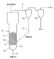
- FIG. 2 is an explanatory view showing an embodiment of a pyrolysis process in a pyrolysis furnace in the method of the present invention.
- FIG. 3 is an explanatory diagram showing an outline of the gasification test apparatus used in the examples.
- an organic substance decomposition catalyst (hereinafter simply referred to as “catalyst” for convenience of explanation) is mixed with the organic substance and molded into a composite granulated product. Is put into a thermal decomposition furnace to thermally decompose organic substances.
- the organic substance and the catalyst are arranged close to each other in the composite granulated product, and the contact area between the two is increased. Therefore, the organic substance can be efficiently thermally decomposed by the action of the catalyst.
- the catalyst since the catalyst has a higher thermal conductivity than the organic material, the rate of temperature increase of the organic material can be increased. As a result, the efficiency of the thermal decomposition of the organic substance by the catalyst can be improved, and the thermal decomposition rate of the organic substance can be effectively increased.
- the organic substance (solid) to be thermally decomposed there is no particular limitation on the organic substance (solid) to be thermally decomposed, but a high molecular weight organic substance is suitable, and examples thereof include plastic (usually waste plastic) and biomass.
- plastic usually waste plastic
- the plastic include, but are not limited to, polyolefins, PA (polyamide), thermoplastic polyesters, PS (polystyrene), elastomers, thermosetting resins, synthetic rubbers, foamed polystyrene, and the like. It is not a thing.
- Polyolefins include PE (polyethylene) and PP (polypropylene).
- Thermoplastic polyesters include PET (polyethylene terephthalate).
- biomass include, but are not limited to, sewage sludge, paper, wood (for example, construction waste wood, packaging / transport waste wood, thinned wood, etc.).
- the catalyst is preferably in the form of a powder to be dispersed in a composite granulated product with an organic substance.
- the size is not particularly limited, but it is preferable that the size pass through a 0.5 mm sieve.
- a general pyrolysis catalyst such as an FCC catalyst.
- System catalysts are preferred.
- dusts (ironworks generated dust) generated in each step of the steelworks are suitable as a catalyst in the method of the present invention because they are mainly composed of iron and are inexpensive.
- a typical example of dust generated in a steel mill includes, but is not limited to, converter dust.
- converter dust is most suitable as a catalyst in the method of the present invention because of its high iron component ratio and very high thermal conductivity.
- Converter dust is iron-containing dust generated in a steelmaking process performed using a converter, and examples of the steelmaking process include a dephosphorization process, a decarburization process, and a stainless steel refining process. It is not limited to these.
- the amount of the catalyst added to the organic material may be appropriately selected depending on the organic material and the type of the catalyst. However, when the organic material is plastic or biomass, and the catalyst is dust generated from a steel mill (converter dust, etc.), 10 About 60 mass% is desirable. When the addition amount of the catalyst is less than 10% by mass of the organic substance, the contact area between the catalyst and the organic substance is reduced, and the effect of the present invention is reduced. On the other hand, when the addition amount of the catalyst exceeds 60% by mass of the organic substance, it becomes difficult to form a mixture of the organic substance and the catalyst.
- the organic material needs to be of a size that allows the catalyst to be uniformly mixed. For this reason, the organic material is crushed in advance as necessary. However, the fineness is sufficient so that the catalyst can be mixed uniformly to some extent, and it is sufficient to pulverize it to pass through a sieve of about 50 mm, and it is not necessary to finely pulverize.
- the binder generally used organic binders can be applied, and PVA (polyvinyl alcohol), starch, and the like can be used.
- the organic substance is a plastic
- the binder since the plastic is generally softened and melted by being heated to 120 ° C. or higher and itself becomes a binder, the binder may or may not be added.
- a composite granulated product having an appropriate strength can be obtained without adding a binder.
- a catalyst and a binder When molding a composite granulated product, it is preferable to add a catalyst and a binder to an organic material in advance and mix thoroughly with a mixer, etc., and thoroughly mix the mixture with a mixer. The strength of the granules can be ensured.
- Any method can be used to form a mixture in which a catalyst is mixed with an organic substance.For example, extrusion molding, ring die molding, briquette forming, etc. can be applied.
- an extruder having a kneading mechanism such as a screw.
- the softening temperature a temperature above the softening point (Vicat softening point) measured according to JIS K7206 (1999) can be used, and as the melting temperature, the differential scanning calorimetric analysis described in JIS K7121 (1987) A temperature higher than the melting point required by (differential scanning calorimetry) can be used.
- the size of the composite granulated product to be molded is not particularly limited, but it is usually preferable that the average particle size is about 3 mm to 50 mm.
- FIG. 1 shows an example of a manufacturing flow for obtaining a composite granulated product when the organic material is waste plastic.
- the waste plastic x is crushed by the crusher 1, and then the metal content is removed by the magnetic separator 2, and then is introduced into the mixer 3.
- the mixer 3 is further charged with a catalyst y (for example, converter dust) and a binder z (for example, a PVA aqueous solution), and these and the waste plastic x are stirred and mixed.
- This mixture is molded by a twin-screw extruder 4 having a kneading mechanism using a screw to obtain a composite granulated product (molded product).
- thermal decomposition method of the composite granulated product all general thermal decomposition methods can be applied.
- a mixed gas containing hydrogen, carbon dioxide gas and water vapor as shown in Patent Document 2 is combined.
- the organic substance may be thermally decomposed at a predetermined temperature by contacting with a granular material (organic substance).
- other types of thermal decomposition methods may be used.
- a fluidized bed type pyrolysis furnace uses a fluidized medium, but depending on the type of catalyst used in the composite granulated product, a catalyst (for example, converter dust) separated by pyrolysis of an organic substance is used as the fluidized medium. Can play a role. Therefore, when using such a catalyst, if a granular material of the same type as the catalyst is used as a fluid medium at the start of operation, the fluid medium will be supplied through the composite granulated material. There is no need to supply the medium in a simple manner.
- a catalyst for example, converter dust
- FIG. 2 shows one embodiment of the pyrolysis process in such a fluidized bed type pyrolysis furnace, in which 5 is a fluidized bed type pyrolysis furnace, and A is a fluidized bed.
- a flowing gas mixed gas
- wind box 51 wind box
- a fluidized bed A made of a fluidized medium is formed above the plate 50.
- the composite granulated product is supplied to the fluidized bed A from the upper part of the pyrolysis furnace 5, and the organic substance of the composite granulated product is pyrolyzed in the fluidized bed A to become a gas product.
- the catalyst separated from the organic substance becomes a part of the fluidized medium.
- the discharge pipe 7 is provided with a primary dust collector 8a and a secondary dust collector 8b.
- the primary dust collector 8a mainly collects a fluid medium
- the secondary dust collector 8b mainly collects organic ash.
- the gas after the fluid medium is collected by the primary dust collector 8a is supplied to the secondary dust collector 8b.
- the gas after the ash is collected by the secondary dust collector 8b is discharged to the outside of the secondary dust collector 8b and collected. Thereby, the high calorific value gas which is the collection object is collected.
- the collected matter mainly composed of the fluid medium collected by the primary dust collector 8 a may be circulated to the pyrolysis furnace 5 through the return pipe 9. Further, since the catalyst separated from the organic substance becomes a part of the fluid medium, in order to keep the amount of fluid medium in the system constant, a part of the fluid medium is extracted from the extraction part 52 as necessary. May be. Further, the product gas is washed with a scrubber and can be used as fuel after removing fine particles, oil, etc. that could not be separated by a dust collector. The oil recovered in the scrubber wash water is recovered through an oil-water separator and can be used as fuel. As the oil / water separator, a filter type, an inclined plate type or the like can be applied.
- a composite granulated product of waste plastic and converter dust (catalyst) whose main component is a metal such as iron was produced as follows.
- the waste plastic was crushed to about 50 mm or less with a crusher, and then the metal content was removed with a magnetic separator.
- This waste plastic is divided into 5% PVA aqueous solution (binder) in a proportion of 3% of the waste plastic mass (PVA is 0.15 mass% of the waste plastic) and converter dust (waste plastic) having a harmonic mean diameter of about 100 ⁇ m as a catalyst.
- the mixture is thoroughly stirred and mixed, and then granulated (molded) by a twin screw extruder, and the diameter of the converter dust is 4 mm ⁇ ⁇ length 10
- a composite granulated product of ⁇ 20 mm was produced.
- the twin screw extruder used had a die diameter of 4 mm and a die temperature of 190 ° C.
- the components of the waste plastic mainly consisted of polyethylene, polystyrene and polypropylene, and the kneading temperature was 160 ° C.
- a gasification test was performed on the composite granulated product obtained as described above (Example of the present invention).
- the plastic in the composite granulated product was gasified at 600 ° C., and the gas lower heating value, gasification rate, etc. were determined from the measured gas generation amount and gas composition.
- 10 is a fluidized bed gasification furnace (11 is a heater).
- a fluidized gas is introduced through the gas supply pipe 12 below the dispersion plate 100, and the fluidized gas is blown out of the dispersion plate 100, thereby forming a fluidized bed A above the dispersion plate 100.
- the raw material (granulated material) to be gasified is supplied into the furnace from the upper part of the fluidized bed gasification furnace 10 through the raw material supply means 13 including a holding container 130 and a quantitative supply screw 131.
- the gas in the fluidized bed gasification furnace 10 is taken out through the discharge pipe 14 and cooled by the gas cooler 15 (18 is a gas trap), and then the gas flow rate is continuously measured by the mass flow meter 16.
- the gas composition is measured by a gas chromatography equipment 17.
- the inner diameter of the fluidized bed gasification furnace 10 in which the fluidized bed A is formed was 66 mm.
- converter dust having the same harmonic average diameter of 100 ⁇ m as the catalyst was used.
- the supply rate of the composite granulated product through the raw material supply means 13 was 300 g / h.
- a mixed gas of H 2, N 2, CO 2 , H 2 O and 4L / min feed was used as a fluidizing gas.
- a comparative example after crushing with a crusher, only the waste plastic from which the metal content was removed with a magnetic separator was granulated (molded) with a twin-screw extruder, and this waste plastic granulated product was the same as above. A gasification test was conducted. The waste plastic and waste plastic granulated material crushed by the crusher were each approximately the same size as in the above examples.
- Table 1 shows the gasification test results of the present invention and the comparative example.
- the gasification rate was greatly improved and the generated gas heat generation amount was very high, although the waste plastic content rate was relatively small and the waste plastic supply amount was small. This is considered to be because the gasification reaction rate is increased by the catalyst dispersed in the composite granulated product.
- the waste plastic compounding ratio and the converter dust compounding ratio in Table 1 indicate the respective proportions in the granulated product.
- the amount of added PVA is approximated to zero and each value is shown.
Landscapes
- Chemical & Material Sciences (AREA)
- Engineering & Computer Science (AREA)
- Organic Chemistry (AREA)
- Oil, Petroleum & Natural Gas (AREA)
- Life Sciences & Earth Sciences (AREA)
- Environmental & Geological Engineering (AREA)
- Chemical Kinetics & Catalysis (AREA)
- Wood Science & Technology (AREA)
- General Chemical & Material Sciences (AREA)
- Hydrology & Water Resources (AREA)
- Water Supply & Treatment (AREA)
- Combustion & Propulsion (AREA)
- Medicinal Chemistry (AREA)
- Sustainable Development (AREA)
- Health & Medical Sciences (AREA)
- Polymers & Plastics (AREA)
- Physics & Mathematics (AREA)
- Thermal Sciences (AREA)
- Materials Engineering (AREA)
- Separation, Recovery Or Treatment Of Waste Materials Containing Plastics (AREA)
- Processing Of Solid Wastes (AREA)
- Treatment Of Sludge (AREA)
- Catalysts (AREA)
Abstract
Description
また、特許文献2には、冶金炉(metallurgical furnace)から発生する一酸化炭素を含むガスに水蒸気を添加し、シフト反応(shift reaction)によって生成した水素、水蒸気、炭酸ガスを含むガスにより有機物質を分解する方法が示されている。この方法によれば、水素化、水素化分解(hydrogenolysis)、水蒸気改質(steam reforming)、炭酸ガス改質(carbon dioxide reforming)よりも、重質化(producing heavy products)を抑制し、400~800℃で効率よく有機物質の分解・ガス化を行うことができる。
また、特許文献2に示される方法は、改質ガスを用いることにより、低温度で有機物質を分解することが可能であるが、一般にプラスチックをはじめとする有機物質は熱伝導度が非常に低く、昇温に時間がかかるため、分解処理量に限界がある。特にプラスチックの場合、反応炉内に過剰な量の原料を投入すると、溶融状態のプラスチックどうしが融着し、反応炉内が閉塞するといった致命的な問題が発生する恐れがある。
本発明は、このような知見に基づきなされたもので、以下を要旨とするものである。
[2]上記[1]の熱分解方法において、有機物質分解触媒が金属系触媒である有機物質の熱分解方法。
[3]上記[1]の熱分解方法において、有機物質分解触媒が製鉄所発生ダストである有機物質の熱分解方法。
[5]上記[1]~[4]のいずれかの熱分解方法において、複合造粒物を流動層式の熱分解炉に投入して有機物質を熱分解する有機物質の熱分解方法。
[6]上記[5]の熱分解方法において、流動層の流動媒体が、有機物質分解触媒と同種の粉粒物である有機物質の熱分解方法。
また、複合造粒物を流動層式(fluid bed type)の熱分解炉に投入して有機物質の熱分解を行う方法では、複合造粒物は有機物質単味に較べて比重が大きいため流動層下部に下降しやすくなり、流動層内における反応領域を広げることができるため、有機物質の処理量をさらに増大させることができる。
プラスチックとしては、例えば、ポリオレフィン類、PA(polyamide)、熱可塑性ポリエステル類、PS(polystyrene)、エラストマー類、熱硬化性樹脂類、合成ゴム類、発砲スチロールなどが挙げられるが、これらに限定されるものではない。ポリオレフィン類は、PE(polyethylene)やPP(polypropylene)を含む。熱可塑性ポリエステル類は、PET(polyethylene terephthalate)含む。
また、バイオマスとしては、例えば、下水汚泥、紙、木材(例えば、建設廃木材、梱包・運送廃木材、間伐材など)などが挙げられるが、これらに限定されるものではない。
成形される複合造粒物の強度を確保するため、有機物質と触媒を混合する際に、適量のバインダーを添加することが好ましい。バインダーとしては、一般的に用いられる有機バインダーが適用可能であり、PVA(ポリビニルアルコール)、でんぷん等を用いることができる。
なお、有機物質がプラスチックである場合は、一般に120℃以上に加熱されることによりプラスチックが軟化・溶融し、それ自体がバインダーとなるため、バインダーを添加してもしなくともよい。成形方法によってはバインダーを添加することなく、適正な強度の複合造粒物を得ることができる。
有機物質に触媒を混合した混合物を成形する方法は任意であり、例えば、押出成形(extrusion molding)、リングダイ成形(ring die molding)、ブリケット成形(briquette forming)などが適用可能であるが、有機物質と触媒の均一混合性を高めるためには、特にスクリュー等による混錬機構を有する押出成形機による成形が好ましい。この際、プラスチックの80質量%以上が軟化もしくは溶融する温度で混練することがさらに好ましい。軟化する温度としてはJIS K7206(1999)に準拠して測定される軟化点(Vicat softening point)以上の温度を用いることができ、溶融する温度としてはJIS K7121(1987)に記載の示差走査熱量分析(differential scanning calorimetry)にて求められる融点以上の温度を用いることができる。
成形される複合造粒物の大きさに特に制限はないが、通常、平均粒径で3mm~50mm程度とすることが好ましい。複合造粒物の平均粒径を3mm未満とするには、有機物質の微粉砕が必要となるため非常に大きな労力が必要となり、一方、複合造粒物の平均粒径(多粒子の重量平均粒径)が50mmを超えると、気体との反応表面積が減少し、ガス化率が大きく減少するおそれがある。
複合造粒物(有機物質)の熱分解方法は、一般的な熱分解方法がすべて適用可能であり、例えば、特許文献2に示されるような水素、炭酸ガス及び水蒸気を含む混合ガスを複合造粒物(有機物質)に接触させ、所定の温度で有機物質を熱分解してもよい。また、他の方式の熱分解方法でもよい。
また、流動層式の熱分解炉では流動媒体が用いられるが、複合造粒物に使用する触媒の種類によっては、有機物質の熱分解によって分離した触媒(例えば、転炉ダスト)が流動媒体の役割を果たすことができる。したがって、そのような触媒を用いる場合には、操業開始時に、触媒と同種の粉粒物を流動媒体として使用すれば、以降は複合造粒物を通じて流動媒体が供給されることになるので、流動媒体を単味で供給する必要がなくなる。
熱分解炉5では、ガス供給管6を通じて分散板50の下側の風箱部51(wind box)に流動ガス(混合ガス)が導入され、この流動ガスが分散板50から吹き出すことにより、分散板50の上方に流動媒体による流動層Aが形成される。複合造粒物は熱分解炉5の上部から流動層Aに供給され、この流動層A内で複合造粒物の有機物質が熱分解され、気体生成物となる。一方、有機物質から分離した触媒は、流動媒体の一部となる。
1次集塵機8aで捕集された流動媒体を主体とする捕集物は、返送管9を通じて熱分解炉5に循環されるようにしてもよい。
また、有機物質から分離した触媒が流動媒体の一部となるので、系内の流動媒体量を一定に維持するため、必要に応じて、抜出部52から流動媒体の一部を抜き出すようにしてもよい。
さらに生成ガスはスクラバーで水洗され、集塵機で分離できなかった微粒子や油分等を取り除いた後、燃料として使用できる。スクラバーの洗浄水中に回収された油分は、油水分離装置を通して回収されたのち、燃料として使用できる。油水分離装置としては、フィルター式、傾斜板方式などの方式を適用可能である。
図3において、10は流動層ガス化炉(11はその加熱ヒータ)である。この流動層ガス化炉10では、分散板100の下方にガス供給管12を通じて流動ガスが導入され、この流動ガスが分散板100から吹き出すことで分散板100の上方に流動層Aが形成される。ガス化する原料(造粒物)は、保持容器130と定量供給用スクリュー131等からなる原料供給手段13を通じて流動層ガス化炉10の上部から炉内に供給される。流動層ガス化炉10内のガスは、排出管14を通じて取り出され、ガス冷却機15で冷却された後(18はガストラップ)、マスフローメーター16でガス流量が連続的に測定され、さらに、ガスクロマトグラフ装置17(gas chromatography equipment)でガス組成が測定される。流動層Aが形成される流動層ガス化炉10の内径は66mmとした。
また、比較例として、破砕機で破砕した後、磁選機で金属分を取り除いた廃プラスチックのみを二軸押出成形機にて造粒(成形)し、この廃プラスチック造粒物について、上記と同様のガス化試験を実施した。破砕機で破砕した廃プラスチックおよび廃プラスチック造粒物は、それぞれ上記実施例とほぼ同じ大きさであった。
本発明例と比較例のガス化試験の結果を表1に示す。本発明例では、相対的に廃プラスチック配合率が小さく、廃プラスチックの供給量が少ないにもかかわらず、ガス化率が大幅に向上し、生成ガス発熱量も非常に高くなった。これは複合造粒物内で分散した触媒によりガス化反応速度が高まるためであると考えられる。また、表1中の廃プラスチック配合率と転炉ダスト配合率は、造粒物中に占めるそれぞれの割合を示している。本発明例においては、添加したPVAの量をゼロと近似して、それぞれの値を示している。
ガス化率は廃プラスチック中の炭素が生成ガス中へ移行した割合を示し、以下の式で示される。
ガス化率=(生成ガス中炭素量(kg/h)-流動ガス中炭素量(kg/h))÷廃プラスチック中炭素量(kg/h)×100

2 磁選機
3 ミキサー
4 二軸押出成形機
5 熱分解炉
6 ガス供給管
7 排出管
8a 1次集塵機
8b 2次集塵機
9 返送管
10 流動層ガス化炉
11 加熱ヒータ
12 ガス供給管
13 原料供給手段
130 保持容器
131 定量供給用スクリュー
14 排出管
15 ガス冷却機
16 マスフローメーター
17 ガスクロマトグラフ装置
18 ガストラップ
50 分散板
51 風箱部
52 抜出部
100 分散板
x 廃プラスチック
y 触媒
z バインダー
A 流動層
Claims (6)
- 有機物質に有機物質分解触媒を混合し、成形して複合造粒物とし、この複合造粒物を熱分解炉に投入して有機物質を熱分解する有機物質の熱分解方法。
- 有機物質分解触媒が金属系触媒である請求項1に記載の有機物質の熱分解方法。
- 有機物質分解触媒が製鉄所発生ダストである請求項1に記載の有機物質の熱分解方法。
- 製鉄所発生ダストが転炉ダストである請求項3に記載の有機物質の熱分解方法。
- 複合造粒物を流動層式の熱分解炉に投入して有機物質を熱分解する請求項1~4のいずれかに記載の有機物質の熱分解方法。
- 流動層の流動媒体が、有機物質分解触媒と同種の粉粒物である請求項5に記載の有機物質の熱分解方法。
Priority Applications (6)
| Application Number | Priority Date | Filing Date | Title |
|---|---|---|---|
| CN201580041585.4A CN106661266B (zh) | 2014-07-31 | 2015-07-30 | 有机物质的热分解方法 |
| EP15826486.1A EP3144345B1 (en) | 2014-07-31 | 2015-07-30 | Thermal decomposition method for organic substances |
| JP2015550503A JP6237788B2 (ja) | 2014-07-31 | 2015-07-30 | 有機物質の熱分解方法および有機物質の熱分解生成物の製造方法 |
| US15/500,356 US20170247618A1 (en) | 2014-07-31 | 2015-07-30 | Method of thermal decomposition of organic substance (as amended) |
| KR1020177002523A KR102007101B1 (ko) | 2014-07-31 | 2015-07-30 | 유기 물질의 열분해 방법 |
| DK15826486.1T DK3144345T3 (da) | 2014-07-31 | 2015-07-30 | Fremgangsmåde til termisk nedbrydning af organiske stoffer |
Applications Claiming Priority (2)
| Application Number | Priority Date | Filing Date | Title |
|---|---|---|---|
| JP2014155653 | 2014-07-31 | ||
| JP2014-155653 | 2014-07-31 |
Publications (1)
| Publication Number | Publication Date |
|---|---|
| WO2016017176A1 true WO2016017176A1 (ja) | 2016-02-04 |
Family
ID=55217085
Family Applications (1)
| Application Number | Title | Priority Date | Filing Date |
|---|---|---|---|
| PCT/JP2015/003844 Ceased WO2016017176A1 (ja) | 2014-07-31 | 2015-07-30 | 有機物質の熱分解方法 |
Country Status (7)
| Country | Link |
|---|---|
| US (1) | US20170247618A1 (ja) |
| EP (1) | EP3144345B1 (ja) |
| JP (1) | JP6237788B2 (ja) |
| KR (1) | KR102007101B1 (ja) |
| CN (1) | CN106661266B (ja) |
| DK (1) | DK3144345T3 (ja) |
| WO (1) | WO2016017176A1 (ja) |
Families Citing this family (5)
| Publication number | Priority date | Publication date | Assignee | Title |
|---|---|---|---|---|
| US11242494B2 (en) | 2013-01-28 | 2022-02-08 | Aries Clean Technologies Llc | System and process for continuous production of contaminate free, size specific biochar following gasification |
| CA3028115A1 (en) | 2016-06-21 | 2017-12-28 | Golden Renewable Energy, LLC | Char separator and method |
| US20170361268A1 (en) * | 2016-06-21 | 2017-12-21 | Golden Renewable Energy | Char separator |
| US20230114144A1 (en) * | 2020-03-24 | 2023-04-13 | Sekisui Chemical Co., Ltd. | Pyrolysis gas purification/cooling device, pyrolysis gas purification/cooling method, organic substance production device, and method for producing organic substance |
| CN114686272A (zh) * | 2020-12-27 | 2022-07-01 | 新疆宜化化工有限公司 | 一种提高气化过程中煤灰熔点的复配剂及混合工艺 |
Citations (6)
| Publication number | Priority date | Publication date | Assignee | Title |
|---|---|---|---|---|
| JPH08253601A (ja) * | 1995-03-17 | 1996-10-01 | Mitsui Eng & Shipbuild Co Ltd | 易熱分解性プラスチックおよびその製造法ならびにこれを用いたプラスチック熱分解法 |
| JPH10245568A (ja) * | 1997-03-03 | 1998-09-14 | Densen Sogo Gijutsu Center | 熱分解油化装置 |
| JP2005015700A (ja) * | 2003-06-27 | 2005-01-20 | Jfe Steel Kk | バイオマスからのフェロコークスの製造方法 |
| JP2005111394A (ja) * | 2003-10-09 | 2005-04-28 | Jfe Holdings Inc | 有機系廃棄物の処理方法 |
| JP2010013657A (ja) * | 2006-01-26 | 2010-01-21 | Kitakyushu Foundation For The Advancement Of Industry Science & Technology | 廃プラスチックの接触分解方法及び廃プラスチックの接触分解装置 |
| JP2014037524A (ja) * | 2012-07-18 | 2014-02-27 | Jfe Steel Corp | 有機物質の低分子化方法 |
Family Cites Families (6)
| Publication number | Priority date | Publication date | Assignee | Title |
|---|---|---|---|---|
| US5554207A (en) * | 1994-11-25 | 1996-09-10 | Usx Corporation | Process of recycling iron oxides and plastics in steelmaking |
| JP2001323308A (ja) * | 2000-03-09 | 2001-11-22 | Nkk Corp | 廃プラスチックの処理方法 |
| US6802886B2 (en) * | 2000-06-05 | 2004-10-12 | Midrex Technologies, Inc. | Method of producing a metallized briquette |
| JP5059379B2 (ja) * | 2006-11-16 | 2012-10-24 | 株式会社神戸製鋼所 | 高炉装入原料用ホットブリケットアイアンおよびその製造方法 |
| KR100791216B1 (ko) * | 2007-03-15 | 2008-01-03 | 구재삭 | 상향식 이동상 촉매에 의한 접촉촉매분해 방법과 그장치 |
| CN103154201B (zh) | 2010-08-31 | 2014-11-05 | 杰富意钢铁株式会社 | 有机物质的低分子化方法及冶金炉产生的废气的利用方法 |
-
2015
- 2015-07-30 EP EP15826486.1A patent/EP3144345B1/en not_active Not-in-force
- 2015-07-30 CN CN201580041585.4A patent/CN106661266B/zh not_active Expired - Fee Related
- 2015-07-30 KR KR1020177002523A patent/KR102007101B1/ko not_active Expired - Fee Related
- 2015-07-30 JP JP2015550503A patent/JP6237788B2/ja active Active
- 2015-07-30 WO PCT/JP2015/003844 patent/WO2016017176A1/ja not_active Ceased
- 2015-07-30 DK DK15826486.1T patent/DK3144345T3/da active
- 2015-07-30 US US15/500,356 patent/US20170247618A1/en not_active Abandoned
Patent Citations (6)
| Publication number | Priority date | Publication date | Assignee | Title |
|---|---|---|---|---|
| JPH08253601A (ja) * | 1995-03-17 | 1996-10-01 | Mitsui Eng & Shipbuild Co Ltd | 易熱分解性プラスチックおよびその製造法ならびにこれを用いたプラスチック熱分解法 |
| JPH10245568A (ja) * | 1997-03-03 | 1998-09-14 | Densen Sogo Gijutsu Center | 熱分解油化装置 |
| JP2005015700A (ja) * | 2003-06-27 | 2005-01-20 | Jfe Steel Kk | バイオマスからのフェロコークスの製造方法 |
| JP2005111394A (ja) * | 2003-10-09 | 2005-04-28 | Jfe Holdings Inc | 有機系廃棄物の処理方法 |
| JP2010013657A (ja) * | 2006-01-26 | 2010-01-21 | Kitakyushu Foundation For The Advancement Of Industry Science & Technology | 廃プラスチックの接触分解方法及び廃プラスチックの接触分解装置 |
| JP2014037524A (ja) * | 2012-07-18 | 2014-02-27 | Jfe Steel Corp | 有機物質の低分子化方法 |
Also Published As
| Publication number | Publication date |
|---|---|
| JPWO2016017176A1 (ja) | 2017-04-27 |
| KR20170027803A (ko) | 2017-03-10 |
| CN106661266A (zh) | 2017-05-10 |
| EP3144345A1 (en) | 2017-03-22 |
| KR102007101B1 (ko) | 2019-08-02 |
| EP3144345B1 (en) | 2019-06-19 |
| DK3144345T3 (da) | 2019-07-22 |
| EP3144345A4 (en) | 2017-05-31 |
| US20170247618A1 (en) | 2017-08-31 |
| CN106661266B (zh) | 2020-09-25 |
| JP6237788B2 (ja) | 2017-11-29 |
Similar Documents
| Publication | Publication Date | Title |
|---|---|---|
| JP7365360B2 (ja) | 固体複合体の製造方法 | |
| JP6227293B2 (ja) | 有機物質の低分子化方法 | |
| JP6237788B2 (ja) | 有機物質の熱分解方法および有機物質の熱分解生成物の製造方法 | |
| CN117940534A (zh) | 用于产生具有高固定碳含量和经优化的反应性的生物碳团粒的方法及由其获得的生物碳团粒 | |
| JP6070580B2 (ja) | 有機物質の低分子化方法および低分子化システム | |
| KR20020052147A (ko) | 가연성 폐기물의 처리방법 | |
| US12270002B2 (en) | Process of treating carbonaceous material and apparatus therefor | |
| JP5999114B2 (ja) | 有機物質の低分子化方法および低分子化システム | |
| JP2012087222A (ja) | 炭素質原料の処理方法及び処理装置 | |
| JP6172532B2 (ja) | 有機物質の低分子化処理及び廃棄物の処理方法 | |
| CN113891945A (zh) | 生产聚合物产品的方法 | |
| US20210054289A1 (en) | Industrial complex for the production of charcoal | |
| JP2025505478A (ja) | 熱分解を使用して廃タイヤからカーボンブラックを製造するシステム及び方法 | |
| CN1114675C (zh) | 两段法大块冷压型焦生产工艺 | |
| JP2014088457A (ja) | 廃棄物の炭化処理方法及び炭化装置 | |
| WO2016075912A1 (ja) | 有機物質の熱分解方法、有機物質の熱分解生成物の製造方法及び有機物質の熱分解炉 | |
| CN110452740B (zh) | 一种强化双组分固体颗粒混合的快速流化反应系统 | |
| JP6210157B2 (ja) | 有機物質分解用触媒、その製造方法および有機物質の低分子化方法 | |
| JP2006241442A (ja) | 廃プラスチックの処理方法 | |
| JP2008266411A (ja) | 廃棄プラスチックを用いた高炉用コークスの製造方法 | |
| JP2003292318A (ja) | 活性炭の製造方法 | |
| JP6519020B2 (ja) | 水素製造装置及び水素製造方法 | |
| JP6197266B2 (ja) | 改質炭の製造方法 | |
| WO2026069929A1 (ja) | 有機物質の低分子化方法 | |
| JP2004167389A (ja) | ごみ処理方法及びその処理装置 |
Legal Events
| Date | Code | Title | Description |
|---|---|---|---|
| ENP | Entry into the national phase |
Ref document number: 2015550503 Country of ref document: JP Kind code of ref document: A |
|
| 121 | Ep: the epo has been informed by wipo that ep was designated in this application |
Ref document number: 15826486 Country of ref document: EP Kind code of ref document: A1 |
|
| REEP | Request for entry into the european phase |
Ref document number: 2015826486 Country of ref document: EP |
|
| WWE | Wipo information: entry into national phase |
Ref document number: 2015826486 Country of ref document: EP |
|
| ENP | Entry into the national phase |
Ref document number: 20177002523 Country of ref document: KR Kind code of ref document: A |
|
| WWE | Wipo information: entry into national phase |
Ref document number: 15500356 Country of ref document: US |
|
| NENP | Non-entry into the national phase |
Ref country code: DE |