WO2016020480A1 - Support pour surface d'appareils approximativement rectangulaires tels les tablettes numériques ou les smartphones - Google Patents
Support pour surface d'appareils approximativement rectangulaires tels les tablettes numériques ou les smartphones Download PDFInfo
- Publication number
- WO2016020480A1 WO2016020480A1 PCT/EP2015/068166 EP2015068166W WO2016020480A1 WO 2016020480 A1 WO2016020480 A1 WO 2016020480A1 EP 2015068166 W EP2015068166 W EP 2015068166W WO 2016020480 A1 WO2016020480 A1 WO 2016020480A1
- Authority
- WO
- WIPO (PCT)
- Prior art keywords
- holder
- holder according
- connecting elements
- holding frame
- retaining clip
- Prior art date
- Legal status (The legal status is an assumption and is not a legal conclusion. Google has not performed a legal analysis and makes no representation as to the accuracy of the status listed.)
- Ceased
Links
Images








Classifications
-
- H—ELECTRICITY
- H04—ELECTRIC COMMUNICATION TECHNIQUE
- H04M—TELEPHONIC COMMUNICATION
- H04M1/00—Substation equipment, e.g. for use by subscribers
- H04M1/02—Constructional features of telephone sets
- H04M1/04—Supports for telephone transmitters or receivers
-
- B—PERFORMING OPERATIONS; TRANSPORTING
- B60—VEHICLES IN GENERAL
- B60R—VEHICLES, VEHICLE FITTINGS, OR VEHICLE PARTS, NOT OTHERWISE PROVIDED FOR
- B60R11/00—Arrangements for holding or mounting articles, not otherwise provided for
-
- B—PERFORMING OPERATIONS; TRANSPORTING
- B60—VEHICLES IN GENERAL
- B60R—VEHICLES, VEHICLE FITTINGS, OR VEHICLE PARTS, NOT OTHERWISE PROVIDED FOR
- B60R11/00—Arrangements for holding or mounting articles, not otherwise provided for
- B60R11/02—Arrangements for holding or mounting articles, not otherwise provided for for radio sets, television sets, telephones, or the like; Arrangement of controls thereof
-
- B—PERFORMING OPERATIONS; TRANSPORTING
- B60—VEHICLES IN GENERAL
- B60R—VEHICLES, VEHICLE FITTINGS, OR VEHICLE PARTS, NOT OTHERWISE PROVIDED FOR
- B60R11/00—Arrangements for holding or mounting articles, not otherwise provided for
- B60R11/02—Arrangements for holding or mounting articles, not otherwise provided for for radio sets, television sets, telephones, or the like; Arrangement of controls thereof
- B60R11/0229—Arrangements for holding or mounting articles, not otherwise provided for for radio sets, television sets, telephones, or the like; Arrangement of controls thereof for displays, e.g. cathodic tubes
- B60R11/0235—Arrangements for holding or mounting articles, not otherwise provided for for radio sets, television sets, telephones, or the like; Arrangement of controls thereof for displays, e.g. cathodic tubes of flat type, e.g. LCD
-
- B—PERFORMING OPERATIONS; TRANSPORTING
- B60—VEHICLES IN GENERAL
- B60R—VEHICLES, VEHICLE FITTINGS, OR VEHICLE PARTS, NOT OTHERWISE PROVIDED FOR
- B60R11/00—Arrangements for holding or mounting articles, not otherwise provided for
- B60R11/02—Arrangements for holding or mounting articles, not otherwise provided for for radio sets, television sets, telephones, or the like; Arrangement of controls thereof
- B60R11/0241—Arrangements for holding or mounting articles, not otherwise provided for for radio sets, television sets, telephones, or the like; Arrangement of controls thereof for telephones
-
- B—PERFORMING OPERATIONS; TRANSPORTING
- B60—VEHICLES IN GENERAL
- B60R—VEHICLES, VEHICLE FITTINGS, OR VEHICLE PARTS, NOT OTHERWISE PROVIDED FOR
- B60R11/00—Arrangements for holding or mounting articles, not otherwise provided for
- B60R11/02—Arrangements for holding or mounting articles, not otherwise provided for for radio sets, television sets, telephones, or the like; Arrangement of controls thereof
- B60R11/0252—Arrangements for holding or mounting articles, not otherwise provided for for radio sets, television sets, telephones, or the like; Arrangement of controls thereof for personal computers, e.g. laptops, notebooks
-
- F—MECHANICAL ENGINEERING; LIGHTING; HEATING; WEAPONS; BLASTING
- F16—ENGINEERING ELEMENTS AND UNITS; GENERAL MEASURES FOR PRODUCING AND MAINTAINING EFFECTIVE FUNCTIONING OF MACHINES OR INSTALLATIONS; THERMAL INSULATION IN GENERAL
- F16M—FRAMES, CASINGS OR BEDS OF ENGINES, MACHINES OR APPARATUS, NOT SPECIFIC TO ENGINES, MACHINES OR APPARATUS PROVIDED FOR ELSEWHERE; STANDS; SUPPORTS
- F16M11/00—Stands or trestles as supports for apparatus or articles placed thereon ; Stands for scientific apparatus such as gravitational force meters
- F16M11/02—Heads
- F16M11/04—Means for attachment of apparatus; Means allowing adjustment of the apparatus relatively to the stand
- F16M11/041—Allowing quick release of the apparatus
-
- F—MECHANICAL ENGINEERING; LIGHTING; HEATING; WEAPONS; BLASTING
- F16—ENGINEERING ELEMENTS AND UNITS; GENERAL MEASURES FOR PRODUCING AND MAINTAINING EFFECTIVE FUNCTIONING OF MACHINES OR INSTALLATIONS; THERMAL INSULATION IN GENERAL
- F16M—FRAMES, CASINGS OR BEDS OF ENGINES, MACHINES OR APPARATUS, NOT SPECIFIC TO ENGINES, MACHINES OR APPARATUS PROVIDED FOR ELSEWHERE; STANDS; SUPPORTS
- F16M11/00—Stands or trestles as supports for apparatus or articles placed thereon ; Stands for scientific apparatus such as gravitational force meters
- F16M11/02—Heads
- F16M11/04—Means for attachment of apparatus; Means allowing adjustment of the apparatus relatively to the stand
- F16M11/06—Means for attachment of apparatus; Means allowing adjustment of the apparatus relatively to the stand allowing pivoting
- F16M11/10—Means for attachment of apparatus; Means allowing adjustment of the apparatus relatively to the stand allowing pivoting around a horizontal axis
-
- F—MECHANICAL ENGINEERING; LIGHTING; HEATING; WEAPONS; BLASTING
- F16—ENGINEERING ELEMENTS AND UNITS; GENERAL MEASURES FOR PRODUCING AND MAINTAINING EFFECTIVE FUNCTIONING OF MACHINES OR INSTALLATIONS; THERMAL INSULATION IN GENERAL
- F16M—FRAMES, CASINGS OR BEDS OF ENGINES, MACHINES OR APPARATUS, NOT SPECIFIC TO ENGINES, MACHINES OR APPARATUS PROVIDED FOR ELSEWHERE; STANDS; SUPPORTS
- F16M11/00—Stands or trestles as supports for apparatus or articles placed thereon ; Stands for scientific apparatus such as gravitational force meters
- F16M11/02—Heads
- F16M11/04—Means for attachment of apparatus; Means allowing adjustment of the apparatus relatively to the stand
- F16M11/06—Means for attachment of apparatus; Means allowing adjustment of the apparatus relatively to the stand allowing pivoting
- F16M11/10—Means for attachment of apparatus; Means allowing adjustment of the apparatus relatively to the stand allowing pivoting around a horizontal axis
- F16M11/105—Means for attachment of apparatus; Means allowing adjustment of the apparatus relatively to the stand allowing pivoting around a horizontal axis the horizontal axis being the roll axis, e.g. for creating a landscape-portrait rotation
-
- F—MECHANICAL ENGINEERING; LIGHTING; HEATING; WEAPONS; BLASTING
- F16—ENGINEERING ELEMENTS AND UNITS; GENERAL MEASURES FOR PRODUCING AND MAINTAINING EFFECTIVE FUNCTIONING OF MACHINES OR INSTALLATIONS; THERMAL INSULATION IN GENERAL
- F16M—FRAMES, CASINGS OR BEDS OF ENGINES, MACHINES OR APPARATUS, NOT SPECIFIC TO ENGINES, MACHINES OR APPARATUS PROVIDED FOR ELSEWHERE; STANDS; SUPPORTS
- F16M11/00—Stands or trestles as supports for apparatus or articles placed thereon ; Stands for scientific apparatus such as gravitational force meters
- F16M11/02—Heads
- F16M11/04—Means for attachment of apparatus; Means allowing adjustment of the apparatus relatively to the stand
- F16M11/06—Means for attachment of apparatus; Means allowing adjustment of the apparatus relatively to the stand allowing pivoting
- F16M11/12—Means for attachment of apparatus; Means allowing adjustment of the apparatus relatively to the stand allowing pivoting in more than one direction
- F16M11/14—Means for attachment of apparatus; Means allowing adjustment of the apparatus relatively to the stand allowing pivoting in more than one direction with ball-joint
-
- F—MECHANICAL ENGINEERING; LIGHTING; HEATING; WEAPONS; BLASTING
- F16—ENGINEERING ELEMENTS AND UNITS; GENERAL MEASURES FOR PRODUCING AND MAINTAINING EFFECTIVE FUNCTIONING OF MACHINES OR INSTALLATIONS; THERMAL INSULATION IN GENERAL
- F16M—FRAMES, CASINGS OR BEDS OF ENGINES, MACHINES OR APPARATUS, NOT SPECIFIC TO ENGINES, MACHINES OR APPARATUS PROVIDED FOR ELSEWHERE; STANDS; SUPPORTS
- F16M11/00—Stands or trestles as supports for apparatus or articles placed thereon ; Stands for scientific apparatus such as gravitational force meters
- F16M11/20—Undercarriages with or without wheels
- F16M11/2007—Undercarriages with or without wheels comprising means allowing pivoting adjustment
- F16M11/2014—Undercarriages with or without wheels comprising means allowing pivoting adjustment around a vertical axis
-
- F—MECHANICAL ENGINEERING; LIGHTING; HEATING; WEAPONS; BLASTING
- F16—ENGINEERING ELEMENTS AND UNITS; GENERAL MEASURES FOR PRODUCING AND MAINTAINING EFFECTIVE FUNCTIONING OF MACHINES OR INSTALLATIONS; THERMAL INSULATION IN GENERAL
- F16M—FRAMES, CASINGS OR BEDS OF ENGINES, MACHINES OR APPARATUS, NOT SPECIFIC TO ENGINES, MACHINES OR APPARATUS PROVIDED FOR ELSEWHERE; STANDS; SUPPORTS
- F16M11/00—Stands or trestles as supports for apparatus or articles placed thereon ; Stands for scientific apparatus such as gravitational force meters
- F16M11/20—Undercarriages with or without wheels
- F16M11/2007—Undercarriages with or without wheels comprising means allowing pivoting adjustment
- F16M11/2035—Undercarriages with or without wheels comprising means allowing pivoting adjustment in more than one direction
- F16M11/2064—Undercarriages with or without wheels comprising means allowing pivoting adjustment in more than one direction for tilting and panning
-
- F—MECHANICAL ENGINEERING; LIGHTING; HEATING; WEAPONS; BLASTING
- F16—ENGINEERING ELEMENTS AND UNITS; GENERAL MEASURES FOR PRODUCING AND MAINTAINING EFFECTIVE FUNCTIONING OF MACHINES OR INSTALLATIONS; THERMAL INSULATION IN GENERAL
- F16M—FRAMES, CASINGS OR BEDS OF ENGINES, MACHINES OR APPARATUS, NOT SPECIFIC TO ENGINES, MACHINES OR APPARATUS PROVIDED FOR ELSEWHERE; STANDS; SUPPORTS
- F16M11/00—Stands or trestles as supports for apparatus or articles placed thereon ; Stands for scientific apparatus such as gravitational force meters
- F16M11/20—Undercarriages with or without wheels
- F16M11/24—Undercarriages with or without wheels changeable in height or length of legs, also for transport only, e.g. by means of tubes screwed into each other
- F16M11/38—Undercarriages with or without wheels changeable in height or length of legs, also for transport only, e.g. by means of tubes screwed into each other by folding, e.g. pivoting or scissors tong mechanisms
-
- F—MECHANICAL ENGINEERING; LIGHTING; HEATING; WEAPONS; BLASTING
- F16—ENGINEERING ELEMENTS AND UNITS; GENERAL MEASURES FOR PRODUCING AND MAINTAINING EFFECTIVE FUNCTIONING OF MACHINES OR INSTALLATIONS; THERMAL INSULATION IN GENERAL
- F16M—FRAMES, CASINGS OR BEDS OF ENGINES, MACHINES OR APPARATUS, NOT SPECIFIC TO ENGINES, MACHINES OR APPARATUS PROVIDED FOR ELSEWHERE; STANDS; SUPPORTS
- F16M13/00—Other supports for positioning apparatus or articles; Means for steadying hand-held apparatus or articles
- F16M13/02—Other supports for positioning apparatus or articles; Means for steadying hand-held apparatus or articles for supporting on, or attaching to, an object, e.g. tree, gate, window-frame, cycle
- F16M13/022—Other supports for positioning apparatus or articles; Means for steadying hand-held apparatus or articles for supporting on, or attaching to, an object, e.g. tree, gate, window-frame, cycle repositionable
-
- G—PHYSICS
- G06—COMPUTING OR CALCULATING; COUNTING
- G06F—ELECTRIC DIGITAL DATA PROCESSING
- G06F1/00—Details not covered by groups G06F3/00 - G06F13/00 and G06F21/00
- G06F1/16—Constructional details or arrangements
- G06F1/1613—Constructional details or arrangements for portable computers
- G06F1/1632—External expansion units, e.g. docking stations
-
- H—ELECTRICITY
- H04—ELECTRIC COMMUNICATION TECHNIQUE
- H04B—TRANSMISSION
- H04B1/00—Details of transmission systems, not covered by a single one of groups H04B3/00 - H04B13/00; Details of transmission systems not characterised by the medium used for transmission
- H04B1/38—Transceivers, i.e. devices in which transmitter and receiver form a structural unit and in which at least one part is used for functions of transmitting and receiving
- H04B1/3827—Portable transceivers
- H04B1/3888—Arrangements for carrying or protecting transceivers
-
- B—PERFORMING OPERATIONS; TRANSPORTING
- B60—VEHICLES IN GENERAL
- B60R—VEHICLES, VEHICLE FITTINGS, OR VEHICLE PARTS, NOT OTHERWISE PROVIDED FOR
- B60R11/00—Arrangements for holding or mounting articles, not otherwise provided for
- B60R2011/0001—Arrangements for holding or mounting articles, not otherwise provided for characterised by position
- B60R2011/0003—Arrangements for holding or mounting articles, not otherwise provided for characterised by position inside the vehicle
-
- B—PERFORMING OPERATIONS; TRANSPORTING
- B60—VEHICLES IN GENERAL
- B60R—VEHICLES, VEHICLE FITTINGS, OR VEHICLE PARTS, NOT OTHERWISE PROVIDED FOR
- B60R11/00—Arrangements for holding or mounting articles, not otherwise provided for
- B60R2011/0042—Arrangements for holding or mounting articles, not otherwise provided for characterised by mounting means
- B60R2011/0049—Arrangements for holding or mounting articles, not otherwise provided for characterised by mounting means for non integrated articles
- B60R2011/0064—Connection with the article
- B60R2011/0071—Connection with the article using latches, clips, clamps, straps or the like
-
- B—PERFORMING OPERATIONS; TRANSPORTING
- B60—VEHICLES IN GENERAL
- B60R—VEHICLES, VEHICLE FITTINGS, OR VEHICLE PARTS, NOT OTHERWISE PROVIDED FOR
- B60R11/00—Arrangements for holding or mounting articles, not otherwise provided for
- B60R2011/0042—Arrangements for holding or mounting articles, not otherwise provided for characterised by mounting means
- B60R2011/0049—Arrangements for holding or mounting articles, not otherwise provided for characterised by mounting means for non integrated articles
- B60R2011/0078—Quick-disconnect two-parts mounting means
-
- B—PERFORMING OPERATIONS; TRANSPORTING
- B60—VEHICLES IN GENERAL
- B60R—VEHICLES, VEHICLE FITTINGS, OR VEHICLE PARTS, NOT OTHERWISE PROVIDED FOR
- B60R11/00—Arrangements for holding or mounting articles, not otherwise provided for
- B60R2011/0042—Arrangements for holding or mounting articles, not otherwise provided for characterised by mounting means
- B60R2011/008—Adjustable or movable supports
- B60R2011/0084—Adjustable or movable supports with adjustment by linear movement in their operational position
-
- B—PERFORMING OPERATIONS; TRANSPORTING
- B60—VEHICLES IN GENERAL
- B60R—VEHICLES, VEHICLE FITTINGS, OR VEHICLE PARTS, NOT OTHERWISE PROVIDED FOR
- B60R11/00—Arrangements for holding or mounting articles, not otherwise provided for
- B60R2011/0042—Arrangements for holding or mounting articles, not otherwise provided for characterised by mounting means
- B60R2011/008—Adjustable or movable supports
- B60R2011/0085—Adjustable or movable supports with adjustment by rotation in their operational position
-
- B—PERFORMING OPERATIONS; TRANSPORTING
- B60—VEHICLES IN GENERAL
- B60R—VEHICLES, VEHICLE FITTINGS, OR VEHICLE PARTS, NOT OTHERWISE PROVIDED FOR
- B60R11/00—Arrangements for holding or mounting articles, not otherwise provided for
- B60R2011/0042—Arrangements for holding or mounting articles, not otherwise provided for characterised by mounting means
- B60R2011/008—Adjustable or movable supports
- B60R2011/0085—Adjustable or movable supports with adjustment by rotation in their operational position
- B60R2011/0089—Adjustable or movable supports with adjustment by rotation in their operational position around three axes, i.e. universally mounted
Definitions
- the invention relates to a holder for flat approximately rectangular devices such as tablet computers or smartphones with different external dimensions for attachment to a component, in particular to a component of a motor vehicle.
- FIGS. 78 to 88 of the aforementioned application are adaptable to different lengths or widths of the devices to be recorded and comprise an approximately rectangular receiving tray with a bottom wall and four side walls which form a circumferential protective edge and a holder arranged within the protective edge a arranged on a longitudinal side of the receiving tray U-shaped receiving pocket which engages around a longitudinal edge of a device inserted into the holder and a arranged on a slidably mounted carriage sprung retaining clip with a hold-down covers the opposite longitudinal edge of a device inserted into the holder.
- An inserted between receiving pocket and retaining clip device is thus held on two opposite longitudinal sides like a clamp in the holder, while the side walls on the narrow sides of the receiving tray form lateral stops, so that the device can not slide laterally out of the holder.
- the width of the light between the side walls is greater than the length of the device inserted in the holder, there is a gap which, in particular if the device is inserted asymmetrically into the holder, is not satisfied aesthetically.
- the device can slide at lateral accelerations in the holder back and forth or even move out of this and cause unpleasant noise, damage or in extreme cases in an accident even injury to passengers.
- the size of the receiving tray must be matched to the largest device to be recorded, so that unnecessarily much space is taken up for smaller devices.
- US 2013/0318775 A1 Another holder for smartphones is known from US 2013/0318775 A1, which includes a holder and a shell for holding a smartphone.
- the shell has in the central region of its back on a coupling portion for bayonet-like attachment of the shell to the holder.
- the arrangement of a coupling on the rear wall of the shell leads to a massive thickening of the rear wall.
- the hole-like depression is aesthetic and unsatisfactory for handling.
- the selective attachment of the shell in the middle of the back wall, especially when using soft materials, leads to high instability of the shell.
- the smartphone is held captive neither by the holder nor by the shell, which can lead to dangerous situations when using the holder in motor vehicles.
- the shell obscures the view of the coupling, which makes attaching the shell massively difficult.
- the object of the invention is to provide a holder for different sized flat approximately rectangular devices such as tablet computers or smartphones, can be held securely with different sized devices in a simple manner and the high protection against injury to passengers in accidents guaranteed.
- the invention is therefore characterized by the fact that the holding frame has second connecting elements on two opposite edges, the first and second connecting elements being complementary to one another such that, when the holding frame is inserted into the holder, the first connecting elements and the second connecting elements engage in one another for mutual fixing, so that the holding frame is not in the holding frame plane and / or can be moved perpendicular to the holding frame plane out of the holder.
- the support frame is thus securely attached to the bracket. Due to the complementary design of the first and second connecting elements, a move out of the holding frame can be reliably prevented.
- the complementary design can be realized by a corresponding geometric design of the connecting elements; However, it is also conceivable that a complementary training results only when the support frame is inserted into the holder. This can be done, for example, by the one connecting element deforming, pressing in or digging into the other connecting element.
- the one connecting element consists of a soft and resilient plastic or foam material, which is pressed by the other connecting element for complementary engagement, so that the holding frame does not move out of the holder in the holding frame plane and / or perpendicular to the holding frame plane can be.
- the holder comprises a holder with preferably clip-shaped first connecting elements with which a holding frame attached to the tablet computer can be positively and detachably connected with correspondingly formed second connecting elements.
- the holding frame has a U-shaped profile and is made of a preferably soft material such as silicone or TPU and preferably encloses all four end faces of the tablet computer completely, largely or in sections.
- the holding frame can be formed in two parts, in which case each a second connecting element is arranged on a respective holding frame part.
- the holding frame is part of a tablet computer receiving case with a bottom wall and the tablet computer preferably on all sides enclosing side walls.
- a shell which may be in particular a protective cover, thus forms a support frame in the context of the invention.
- the casing comprises cover walls on at least two opposite sides, which at least partly cover and / or overlap the device in the edge region on the side of the screen.
- the sheath is made in one piece from an elastic material such as silicone or TPU, so that the cover walls of the sheath can preferably be stretched on all sides over the edge region of the monitor side of the tablet computer and the sheath firmly attached to the tablet computer or can be safely absorbed by the case.
- an elastic material such as silicone or TPU
- the second connecting elements arranged on the holding frame or on the casing are formed on the edges of the holding frame or the casing by the frame or the casing or as separate parts, preferably made of a hard plastic or metal, on the holding frame or arranged the shell or inserted into the holding frame or the shell, glued, molded or otherwise connected to the support frame or the shell.
- the arranged on the holding frame or on the shell second connecting elements are preferably formed as recesses and / or elevations on two opposite edges of the holding frame or the shell.
- the second connecting elements can form in particular receptacles with lateral stops for the first, preferably bracket-shaped, connecting elements arranged on the holder, so that the holding frame or the envelope is positively held in the holder with the tablet computer and can not slide laterally out of the holder ,
- the recesses and / or elevations of the first and second connecting elements may be formed as intermeshing toothings, the number of teeth and their size, shapes and distances depending on the requirements in terms of materials, force and aesthetics to be provided.
- the recesses or depressions and / or elevations or teeth are arranged on the edges, that is on the end faces and / or in the edge region of the front and / or rear of the holding frame or the shell.
- the first connecting elements are clamp-shaped and surround the holding frame or the shell in frontally arranged recesses on the rear, front and / or front of the holding frame or the shell.
- the second connecting elements may be arranged on the two long or on the two short edges of the holding frame or the casings.
- the second connecting elements arranged on two opposite edges of the holding frame or of the envelopes are arranged approximately centrally with respect to the length of the edges of the holding frame or the envelope and in particular symmetrically formed with identical contours such that tablet computers of different formats with holding frames or hulls of different lengths on the edges are held in the holder and, in particular, can also be inserted into the holder in 180 ° different positions.
- the holding frame or the sleeve on two opposite sides and preferably arranged on the two narrow sides, against the interior of the shell or the inside open receiving pockets, which surround two opposite edges of the device in particular on all sides or embrace ,
- the second connecting elements are arranged at the two long edges of the holding frame or the shell and the receiving pockets on the two short edges of the holding frame or the shell or if the receiving pockets on the two long edges of the holding frame or the sheath and the second connecting elements are arranged on the two short edges of the holding frame or the shell.
- the holder comprises two first connecting elements arranged on opposite sides whose spacing can be adjusted and thus adapted to holding frames or casings with different external dimensions.
- the holder can be used very flexible for different sized devices use.
- the two receiving pockets and the two, in particular, clip-shaped connecting elements of the holder together form a frame that encloses the tablet computer substantially on all sides, which means peeling off the case from the tablet computer, in particular in the corner areas, and exposing the device edges in the case prevented a head impact in an accident.
- the edge of the tablet computer is covered outside the two sections for the second connecting elements by a protective edge arranged on the holding frame or on the casing.
- first connecting elements are clamp-shaped and comprise a first retaining clip with a hold-down and a second retaining clip with a hold-down, which engage in the second connecting elements and / or engage around the second connecting elements.
- first connecting elements are clamp-shaped and comprise a first retaining clip with a hold-down and a second retaining clip with a hold-down, which engage in the second connecting elements and / or engage around the second connecting elements.
- the hold-down can be prevented that the holding frame can be moved perpendicular to the holding frame plane out of the holder.
- the second connecting elements on the holding frame or at the edges of the shell with inserts of a stable material such. a hard plastic or metal wire reinforced.
- a stable material such as a hard plastic or metal wire reinforced.
- the holding frame or the shell in the edge area are all around dimensioned so that they form an effective protection against injury to passengers in the vehicle by the sharp-edged tablet computer and against damage to the tablet computer when falling down to the ground.
- the support frame or the shell are preferably as thin and flat and formed without protruding elements so that they do not interfere with the use of the tablet computer outside of vehicles and remain attached as a protective edge or protective cover on the tablet computer, so attaching and removing the holding frame or the case when using the tablet computer with or without holder deleted.
- the first retaining clip is fixedly arranged on the carrier and the second retaining clip is arranged on an extendable slide mounted in or on the carrier.
- the distance between the two retaining clips adjusted and adapted to the size of the device.
- the carriage can thereby be adjustably mounted parallel to the longitudinal axis X - X of the carrier and lockable in different positions with a locking device.
- the locking device can be solved with a button accessible on the end wall of the second retaining clip button.
- a fixed retaining clip and a second - preferably designed as a second slide - movable retaining clip may be arranged on the carrier wherein the two carriages are preferably guided one above the other lying in the carrier and arranged by means of the two carriages of known type a gear synchronously and in opposite directions are movable.
- a support wall is arranged, which forms a fixed stop for the device with holding frame or shell. As a result, the device can be inserted into the holder in exact position.
- the second retaining clip is mounted parallel to the longitudinal axis X - X movable in or on the carriage and biased by a spring against the support wall, so that the hold-down of the retaining clip projects beyond the support wall and the edge of the support frame or the shell with the Covered in the holder device covers.
- wedge-shaped ramps are arranged on the carrier and on the slide, which raise a device inserted into the holder with holding frame or shell when pushing against each slide and carrier until the holding frame or the shell pending on the two downers.
- the rear wall and the hold-down of the first retaining clip and the support wall and the hold-down of the second retaining clip preferably surround the recesses on the support frame or on the shell with the device.
- the holding frame or the casing with the device of the ramp and the rear wall and the hold-down at one edge and the ramp of the support wall and the hold-down on the opposite edge in the recesses are supported and supported on all sides.
- the holder can be connected via a releasable coupling with a plug-in element on the holder and a receiving socket on the component with the component.
- the size of the holder is thus determined largely by the size of the device used in the holder with holding frame or shell, while the size of the holder without a device is very small and compact.
- Fig. 1a shows a perspective view of a first embodiment of a holder for a tablet computer with shell, with a support and a support fixedly arranged on the support bracket and a carrier mounted adjustably mounted in the carriage and a carriage movably mounted retaining clip with the carriage and the movable retaining clip in the retracted positions.
- Fig. 1b shows a perspective view of the holder as shown in Fig. 1a, with the carriage in an extended intermediate position.
- Fig. 1c shows a perspective view of the holder as shown in Fig. 1b with the movable retaining clip in the open position for insertion or removal of a tablet computer with shell.
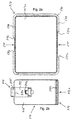
- Fig. 2a shows a plan view from the front of the holder as shown in Fig. 1c.
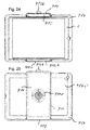
- Fig. 2b shows a plan view from the front of a case with inserted tablet computer.
- FIG. 3a shows a top view from the front of a tablet computer with a sleeve inserted into a holder according to the illustration in FIG. 2a, as shown in FIG. 2b.
- FIG. 3b shows a top view from the rear of a tablet computer with a sleeve inserted into a holder according to the representation in FIG. 2a, as shown in FIG. 2b.
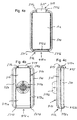
- Fig. 4a shows a plan view from the front of a smartphone used in a holder with shell.
- FIG. 4b shows a plan view from the rear of a smartphone with a sleeve inserted into a holder as shown in FIG. 4a.
- FIG. 4 c shows a side view of a smartphone with a sleeve inserted into a holder, as shown in FIG. 4 a.
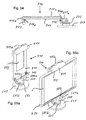
- FIG. 5a shows a perspective view from the front of a further embodiment of a holder for a tablet computer with casing with a carrier and a support bracket fixedly arranged on the carrier and an adjustable support mounted in the carriage and a carriage movably mounted in the support bracket with the carriage and the movable Retaining clip in extended positions.
- Fig. 5b shows a perspective view of the holder as shown in Figure 5a from the rear.
- Fig. 6a shows a plan view from the front of a case with inserted tablet computer.
- Fig. 6b shows a top view from the rear of the shell as shown in Fig. 6a.
- FIG. 7 shows a perspective view of the tablet computer with sheath shown in FIGS. 6a, 6b inserted into the holder shown in FIGS. 5a, 5b.
- Fig. 8 shows a perspective view of a smartphone with a correspondingly reduced casing according to the construction of Fig. 6a, 6b, used in a correspondingly reduced holder according to the construction of Fig. 5a, 5b.
- Fig. 9 shows a perspective view of another embodiment of a shell.
- Fig. 10a shows a sectional view A-A gem. Representation of FIG. 9.
- Fig. 10b shows a sectional view B-B acc. Representation of FIG. 9.
- 11a shows an insert for reinforcing recesses arranged on the longitudinal sides of the shell.
- Fig. 11b shows the insert used in the shell acc. Representation in Fig. 11a.
- Fig. 12 shows a perspective view of another embodiment of a holder for a tablet computer with sleeve with a carrier and a carrier fixedly arranged retaining clip and a carrier mounted adjustably mounted in the carriage and a carriage movably mounted retaining clip with the carriage in the extended position and the movable retaining clip in the open position for insertion and removal of a tablet computer with sheath.
- Fig. 13 shows a front view of the holder of Fig. 12 with the carriage in an intermediate position and the retaining clip in the closed position.
- FIG. 14 shows a side view of the holder as shown in FIG. 13.
- FIG. 14 shows a side view of the holder as shown in FIG. 13.
- Fig. 15 shows a longitudinal sectional view of the holder of Fig. 12 to 14 with a further variant of a locking device for the carriage in the blocking position.
- Fig. 16 shows a longitudinal sectional view of the holder as shown in Fig. 15 with the locking device of the carriage in the release position.
- FIG. 17 shows an exploded perspective view of the locking device of FIGS. 15 and 16.
- Fig. 18 shows a front view of another variant of a case for a tablet computer.
- FIG. 19 shows a side view of the shell of FIG. 18.
- FIG. 20 shows a rear view of the casing of FIGS. 18 and 19
- FIG. 21 shows a perspective view of the casing of FIGS. 18 to 20 from the front.
- FIG. 22 shows a perspective view of the casing according to the representation of FIG. 21 from the front, rotated by 180 °.
- Fig. 23 is an exploded perspective view of the holder with a holder and a case and a tablet computer.
- FIG. 24 shows a view of the holder according to FIG. 23 with the tablet computer inserted in the holder with the case from the front.
- Fig. 25 shows a view of the holder according to FIG. 24 from the rear.
- FIG. 26 shows a perspective view of the holder according to illustrations from FIGS. 23 to 25 from the rear.
- Fig. 27 shows a perspective view of the holder as shown in Fig. 26 from the front.
- Fig. 28 shows a rear view of another variant of a shell with a folded support strip.
- Fig. 29 shows a side view of the sheath of Fig. 28 with the support bar folded out in a first position.
- Fig. 30 shows a side view of the sheath of Fig. 28 with the support bar folded out in a second position.
- Fig. 31 shows a perspective view from the front of another embodiment of a holder, which is rotatably mounted on a support member of a fastening device, in a vertical position with the carriage in the retracted position.
- Fig. 32 shows a view of the holder as shown in Fig. 31 with the carriage in the extended position.
- FIG 33 shows a front view of a tablet computer with a shell in landscape configuration and connecting elements in the form of recesses on the two long edges of the shell.
- Fig. 34 shows a front view of a tablet computer with casing in portrait position and connecting elements in the form of recesses on the two short edges of the shell.
- FIG. 35 shows a front view of the device with tablet computer and casing in the transverse format position as shown in FIG. 33 inserted into the vertically aligned holder with retracted carriage as shown in FIG. 31.
- FIG. 36 shows a front view of the device with tablet computer and casing in the vertical position as shown in FIG. 34 inserted into the vertically oriented holder with the carriage extended as shown in FIG. 32.
- Fig. 37 shows a front view of the device as shown in Fig. 35 with horizontally oriented holder and tablet computer with case in the vertical position.
- Fig. 38 shows a front view of the device as shown in Fig. 36 with horizontally oriented holder and tablet computer with shell in the horizontal position.
- Fig. 39 shows a plan view of a further variant of a holder
- FIG. 40 shows a side view of the holder as shown in FIG. 39.
- FIG. 40 shows a side view of the holder as shown in FIG. 39.
- FIG. 41 shows a cross-sectional view of a detail view of the case with tablet computer as shown in FIG. 33.
- FIG. 41 shows a cross-sectional view of a detail view of the case with tablet computer as shown in FIG. 33.
- FIG. 42 shows a cross-section of a detail view of the casing with tablet computer, inserted into the holder as shown in FIG. 35.
- Fig. 43 shows a plan view of the front side of a shell with an alternative embodiment of the second connecting elements on the two longitudinal edges.
- Fig. 44 shows a plan view of the front side of a shell with an alternative embodiment of the second connecting elements at the two transverse edges.
- Fig. 45 shows a partially sectioned plan view of the front of the case as shown in Fig. 43 with a fitting adapted to the fasteners (partially cut).
- Fig. 46a shows a plan view from the front of a one-piece holding frame.
- FIG. 46b shows a plan view from the rear of the holding frame as shown in FIG. 46a.
- Fig. 47a shows a plan view from the front of a two-part support frame, mounted on a tablet computer.
- FIG. 47b shows a plan view from the rear of the holding frame as shown in FIG. 47a.
- Fig. 48 shows a cross section of the holding frame as shown in Fig. 46a.
- FIG. 49 shows a cross section of the holding frame as shown in FIG. 47a.
- Fig. 50a shows a first embodiment of a smartphone holder for attachment to a windshield of a motor vehicle with a vacuum cleaner in a vertically upright position of use directed against the driver screen.
- Fig. 50b shows the smartphone holder gem. Representation of Fig. 50a in a horizontal non-use position with directed against the support arm screen.
- FIG. 51 shows a side view of the smartphone holder according to the representation of FIG. 50b, fastened to a windshield of a motor vehicle.
- Fig. 52 shows a smartphone holder gem. Construction of Fig. 50a to 51 with a stand for mounting the holder on a flat surface.
- Fig. 53a shows a perspective view of another embodiment of a holder in the position of use.
- FIG. 53b shows the holder according to FIG. 53a in the non-use position.
- FIG. 54 shows a side view of the holder according to FIG. 53b.
- FIG. 55 a shows a further perspective view of the holder according to FIG. 53 a.
- FIG. 55b shows the holder according to FIG. 55a with a tablet computer with shell arranged thereon.
- Fig. 56a shows a perspective view of another embodiment of a holder in the position of use.
- FIG. 56b shows the holder according to FIG. 56a in the non-use position.
- Fig. 57 shows a side view of the holder according to Fig. 56b.
- FIG. 58 a shows a further perspective view of the holder according to FIG. 56 a.
- FIG. 58b shows the holder according to FIG. 56a with a tablet computer with shell arranged thereon.
- Fig. 59a shows a perspective view of another embodiment of a holder in the position of use.
- Fig. 59b shows the holder according to Fig. 59a in non-use position.
- Fig. 60 shows a side view of the holder attached to a receiving socket in non-use position.
- FIG. 61 a shows a further perspective view of the holder according to FIG. 59 a.
- FIG. 61b shows the holder according to FIG. 59a with a tablet computer with shell arranged thereon.
- FIGS. 1a to 3b show a first embodiment of the invention comprising a holder 400 with a holder 410 for a tablet computer 1 provided with a holding frame 500 or a sheath 450, with a carrier 411 and a holding clamp 412 fixedly arranged on the carrier 411, 412a with a hold-down 412b which surrounds one edge of the holding frame 500 or the shell 450 of the tablet computer 1 and a support 411 parallel to the longitudinal axis X - X adjustably mounted and lockable in different positions carriage 413 with a fixed stop in the form of the support wall 413a for the opposite edge of the support frame 500 and the shell 450 of the tablet computer.
- 1 shows a first embodiment of the invention comprising a holder 400 with a holder 410 for a tablet computer 1 provided with a holding frame 500 or a sheath 450, with a carrier 411 and a holding clamp 412 fixedly arranged on the carrier 411, 412a with a hold-down 412b
- linearly displaceable movable retaining clip 414 is arranged with a hold-down 415, which is biased by a spring against the fixed stop 413a on the carriage 413 and the opposite edge of the support frame 500 and the shell 450 of the holder 410 embraces the inserted tablet computer 1.
- the hold-down 412b of the retaining clip 412 and the hold-down 415 of the retaining clip 414 engage around the side edges and cover the edge of the support frame 500 and the shell 450 of the tablet computer 1, so that it can not fall up out of the holder 410.
- the lateral end walls 511a, 511b of the recess 511 and the lateral end walls 521a, 521b of the recess 521 on the holding frame 500 and the shell 450 form lateral stops for the rear wall 412a of the retaining clip 412 and for the support wall 413a on the carriage 413 and the side walls 414a ', 414 a' 'of the retaining clip 414, so that the tablet computer 1 is held in a form-fitting manner in the holder 410 and can not slide laterally out of the holder 410.
- the recesses 511 and 521 on the support frame 500 and the shell 450 are arranged centrally so that the tablet computer 1 is centered in the holder 410.
- a cone 411d of a pivot bearing is arranged with which the holder 410 between portrait and landscape format is rotatably connected to a (not shown) fastening means.
- Figures 4a to 4c show a holder 410 and a shell 450 with integrated support frame 500 correspondingly reduced for receiving a smartphone 1a, but with identical construction as the embodiments described in Figures 1a to 3b, wherein the two recesses 511, 511a, 511b and 521st , 521a, 521b for the retaining clips 414, 412 are arranged on the two short edges of the retaining frame 500.
- FIGS. 5a to 8 show a further embodiment of a holder 410 for a tablet computer (FIGS. 5a-7) and for a smartphone (FIG. 8) likewise of identical design as the exemplary embodiments described in FIGS. 1a to 3b.
- the retaining clip 412 fixedly arranged on the support 411 and the carriage 413 guided in the support 411 with the support wall 413a and the retaining clip 414 movably guided in the carriage 413 with the hold-down 415 have approximately the same width (FIGS. 5a and 5b).
- the recesses 511, 521 arranged at the opposite edges 510, 520 of the holding frame 500 are equally wide, so that the tablet computer 1 with the casing 450 can be inserted into the holder 410 in 180 ° different positions.
- a centrally arranged recess 451 for receiving the support 411 is provided on the outside of the bottom wall 450a of the shell 450.
- the side edges 451 a, 451 b of the recess 451 form additional stops so that the shell 450 can not slide laterally out of the holder 410.
- the release button 411b arranged on the inside of the carrier 411 serves to release the locking of the carriage 413 in the carrier 411 so that the carriage 413 can be displaced in the carrier 411.
- FIGS. 9 to 11b show a further embodiment of a one-piece casing 450 having a bottom wall 450a, two long side walls 500a, 500c, two short side walls 500b, 500d and top walls 515a ', 515b' arranged on the short side walls 500b, 500d.
- Computer 1 arranged housing sections 1 ', 1' '(Fig. 6a) on all sides enclose (Fig. 10a).
- the recesses 511, 511a, 511b and 521, 521a, 521b are arranged, into which the clamp-shaped connecting elements 412, 412a, 412b, 413a, 414, 414a ' , 414a ", 415 (FIGS. 1a, 5a, 5b) of the holder 410.
- the two recesses 511, 511a, 511b and 521, 521a, 521b on the shell 450 are made of a stable material, such as inserts 511 'complementary in contour to the recesses 511, 511a, 511b and 521, 521a, 521b. a hard plastic reinforced (11a, 11b).
- FIGS. 12 to 17 show a further embodiment of a holder 410 for a tablet computer 1 in a casing 450 (FIG. 9), with a carrier 411 and a retaining clip 412 fixedly arranged on the carrier 411, which in the first recess 511 forms an edge of the casing 450 with the tablet computer 1 and a support 411 adjustably mounted and lockable in different positions slide 413 with a fixed stop in the form of a support wall 413a, which engages in the second recess 521 at the opposite edge of the shell 450 of the tablet computer 1 ,
- the slide 413 has a linearly displaceable retaining clip 414 with a hold-down 415 which surrounds the opposite edge of the shell 450 of the tablet computer 1 and which is biased against the rear side of the support wall 413a on the slide 413 by two springs 720 (FIG. 17).
- wedge-shaped ramps 411f, 411e are arranged on the carrier 411 and the carriage 413, which push the tablet computer 1 with sheath 450 inserted into the holder 410 against one another from carriage 413 and support 411 until the sheath 450 abuts against the hold-downs 412b, 415.
- the construction and operating principle of the holder 410 correspond to the description of the holders 410 shown in FIGS. 1a to 2a and FIGS. 5a to 5b, to which reference is made.
- a locking device is used in the embodiment according to FIGS 700 proposed, which blocks the movements of the carriage 413 in both directions of movement and which can be solved via a arranged on the end wall 414b of the retaining clip 414 opening button 413b can be solved.
- the function of the locking device 700 will be explained in more detail with reference to FIGS.
- the carriage 413 is guided in slide guides 411k, 411l (FIG. 13) in the carrier 411. To the slide guides 411k, 411l mutually facing toothed rails 411z are attached.
- a push rod 701 is longitudinally displaceably guided in the bottom plate 414c of the retaining clip 414.
- a cap-shaped button 413 b is mounted with the push rod 701 can be pressed against the force of the push rod spring 703 inward.
- two locking bars 704, 706 movably guided transversely to the push rod 701 are arranged one above the other, which are provided with control grooves 705a, 705b in which a control cam 702 attached to the push rod 701 engages.
- the two locking bars 704, 706 are provided at their ends directed against the toothed rails 411z with toothed segments 704a, 706a, which engage in the toothed rails 411z when the push rod 701 is in the outer inactive position.
- the two locking bolts 704, 706 g are moved with the control cam 702 against each other and the toothed segments 704a, 706a are disengaged from the toothed rails 411k, 411l, so that the carriage 413 is released in both directions is mobile.
- the two locking bars 704, 706g are moved apart with the control cam 702 by the action of the push rod spring 703 and the toothed segments 704a, 706a are brought into engagement with the toothed rails 411k, 4111l so that the carriage 413 moves in both directions is blocked.
- the cam grooves 705a, 705b and the control cam 702 are formed so that the lock bars 704, 706 are mechanically locked in the lock position and can not move relative to each other.
- FIGS. 18 to 22 show a further embodiment of a casing 450 having a bottom wall 450a, two long side walls 500a, 500c, two short side walls 500b, 500d and top walls 515a ', 515b' arranged on the short side walls 500b, 500d.
- Computer 1 arranged housing sections 1 ', 1' '(Fig. 6a) on all sides enclose (Fig. 10a).
- the bracket-shaped connecting elements 412, 412a, 412b, 413a, 414, 414a ', 414a ", 415 on the long side walls 500a, 500c and the receiving pockets 515a, 515b on the short side walls 500b, 500d together form a tablet computer 1 in FIG Essentially encompassing all sides support frame, which ensures a secure connection between the bracket 410 and the tablet computer 1 and prevents detachment of the shell 450 from the tablet computer 1 in the corner areas.
- the bottom wall 450a is somewhat recessed on its rear side 450a 'opposite the peripheral edge 500a, 500b, 500c, 500d.
- a relief-like sign 450a is mounted whose height is approximately flush with the peripheral edge 500a, 500b, 500c, 500d.
- FIG. 23 to 27 show the holder 400 comprising the holder 410 and the sheath 450 and a tablet computer 1 loose (FIG. 23) and mounted (FIGS. 24 to 27) in various views from the front (FIGS. 24 and 27). and from behind ( Figures 25 and 26).
- FIGS. 28 to 30 show an alternative embodiment of the shell 450.
- the bottom wall 450a On the rear side 450a 'of the bottom wall 450a is arranged around a parallel to the long side walls 500a, 500c aligned axis of rotation 452a foldable support bar 452 arranged with the shell 450 with the tablet computer. 1 can be placed in different inclinations on a flat surface.
- the outside 452b of the support strip 452 is aligned approximately with the peripheral edge 500a, 500b, 500c, 500d of the shell 450.
- 31 to 32 show a holder 410 which is rotatably arranged on a support element 600 of a fastening device, so that a tablet computer 1 with sleeve 450 can be rotated from a portrait position to a landscape position and vice versa.
- the holder 410 comprises a carrier 411 with a fixed retaining clip 412 and a carriage 413 which can be displaced linearly in the carrier 411 with a movable retaining clip 414 with a hold-down 415.
- the holder 410 differs according to representations in by a larger displacement of the carriage 413 by the extension of carriage 413 and carriage guide in the carrier 411 is achieved.
- the distance between the retaining clip 412 and 414 is adjustable between a minimum distance (FIG. 31) and a maximum distance (FIG. 32). This results in the minimum and maximum dimensions of the tablet computer 1 which can be accommodated with the shell 450 in the holder 410.
- FIGS. 33 and 34 show two differently sized tablet computers 1A, 1B with different sized cases 450A, 450B.
- the recesses 511A, 521A for the retaining clips 412, 414 are arranged in the middle of the two longitudinal sides
- the recesses 511B, 521B for the retaining clips 412, 414 are arranged in the middle of the two narrow sides.
- 35-38 show that, regardless of which sides of the sheaths 450A, 450B the recesses 511A, 521A and 511B, 521B are arranged, the different sized tablet computers 1A, 1B in the same holder 410 in both portrait and landscape format are usable.
- 39 to 40 show a further embodiment of a holder 410 with the compact design of a wide range of different sized tablet computers 1A, 1B can be covered with sleeves 450A, 450B.
- a holding clamp 630, 630a, 630b and a slide 620 with a supporting wall 622 are mounted one above the other and movable into the pull-out positions shown in FIGS. 39 and 40.
- the retaining clip 630, 630a, 630b and the slide 620 are provided in the known manner with racks 621, 631 and a gear 635 synchronously and in opposite directions movable and adjusted in a desired position to the dimensions of a shell 450A, 450B with a tablet computer 1A , 1B detectable.
- the retaining clip 630, 630a, 630b surrounds the tablet computer 1A, 1B at one edge.
- FIG. 41 shows a detail view of the casing 450A with inserted tablet computer 1A according to the representation of FIG. 33 in the region of the recess 511A in longitudinal section.
- FIG. 42 shows a detailed view of the holder 410 with inserted tablet computer 1A with sheath 450A as shown in FIG. 35 in the region of the retaining clip 414 in longitudinal section.
- the slide 413 guided linearly in the carrier 411 is connected to the ramp 411e with the support wall 413a.
- the retaining clip 414 with the end wall 414b and the hold-down 415 is linearly guided and biased against the support wall 413a of the slider 413.
- the push rod 701 is mounted with the key 423b for deblocking the carriage 413 (Figs. 15-17).
- a tablet computer 1A with a sheath 450A inserted into the holder is lifted as far as slide 413 and carrier 411 are pushed over the wedge-shaped ramps 411f and 411e arranged on the carrier 411 and the carriage 413, until the top of the shell 450A abuts the bottoms of the hold downs 412b, 415.
- the edge of the shell 450A of the tablet computer 1A is enclosed by the ramp 411e and the support wall 413a and the hold-down 415 and supported on all sides.
- the retaining clip 414 is pushed outwards until it no longer covers the shell 450A.
- FIGS. 43 to 45 show two sheaths 450 with an alternative design of the second connecting elements 711, 721, 731, 741 as well as a holder 410 with correspondingly adapted first connecting elements 412, 413a.
- the second connecting elements 711, 721 are arranged centrally on the two longitudinal sides 700a, 700c.
- the second connecting elements 731, 741 are arranged centrally on the two narrow sides 700b, 700d.
- the second connection elements 711, 721, 731, 741 comprise a central tooth 711c, 721c, 731c, 741c and recesses 711a, 711b, 721a, 721b, 731a, 731b, 741a, 741b arranged on both sides of the central tooth 711c, 721c, 731c, 741c.
- first connecting elements 413a ', 413a' ', 413 a' '', 412a ', 412a' ', 412a '', 412a '' which engage in the second arranged on the shell 450 connecting elements 711a, 711b, 711c, 721a, 721b, 721c engage and form a positive interlocking teeth with this prevents lateral slippage of the shell 450 in the holder 410.
- Figures 46a and 46b show a one-piece support frame 500 from the front ( Figure 46a) and from the rear (46b).
- the second connecting elements 511, 511a, 511b and 521, 521a, 521b designed as recesses with lateral stops are arranged centrally on the two longitudinal sides 510, 520 of the holding frame 500.
- Figs. 47a and 47b show a two-part support frame 500A, 500B from the front (Fig. 47a) and from the rear (Fig. 47b).
- the second connecting elements 511, 511a, 511b and 521, 521a, 521b designed as recesses with lateral stops are arranged centrally on the longitudinal sides 510, 520 of the two holding frames 500A, 500B.
- the two support frames 500A, 500B are reinforced with bottom walls 510a, 510b.
- FIG. 48 shows a cross-section of the one-piece holding frame 500 as shown in FIG. 46a.
- FIG. 49 shows a cross section of the two-part holding frame 500A, 500B as shown in FIG. 47a.
- 50a to 51 show a first application example with a fastening device in the form of a vacuum cleaner 601 for mounting the holder 600 on the inside of a windshield 610 of a motor vehicle.
- a support arm 602 is mounted, which is aligned approximately horizontally in the direction of the passenger compartment.
- the carrier arm 602 comprises a first segment 602a fixedly connected to the vacuum suction device 601 in which a second segment 602b is guided linearly extendable.
- a latching device (not shown), the second segment 602b can be detected in the desired pull-out position and released with release buttons 608 arranged on both sides on the side walls of the second segment 602b.
- a first pivot bearing 603 is arranged on which a bearing block 604 is rotatably mounted about a vertical axis of rotation Z 360 °.
- a second pivot bearing is arranged on which a support member 605 is rotatably mounted about a horizontal axis of rotation Y between an approximately horizontal and an approximately vertical position.
- a third pivot bearing 606 is arranged on which a holder 607 for receiving a device (1, 1A, 1B, 1a) about a perpendicular to the broad side of the holder 607 aligned axis of rotation X 360 ° is rotatably mounted.
- All three pivot bearings can be releasably locked in preferred positions.
- the holder 607 with the screen of the device (1, 1A, 1B, 1a) can be placed horizontally against the upper side of the carrier arm 602, on the carrier arm 602 (FIGS Fig. 51), so that the screen device (1, 1A, 1B, 1a) protected from contamination, damage and sunlight and the view of the road are minimally restricted.
- the holder 607 on the second segment 602b can be pulled out of the first segment 602a far enough that the holder 607 is in contact with the device (1, 1A, 1B, 1a) without colliding with the device
- Windscreen 610 can be erected about the axis of rotation Y from the horizontal non-use position in an approximately vertical position of use and the screen of the device (1, 1A, 1B, 1a) about the axes of rotation Y and Z on the user can be aligned (Fig. 50a).
- the bracket 607 can be rotated with the apparatus (1, 1A, 1B, 1a) between portrait and landscape positions and the opening 607a for the charging socket of the apparatus (1, 1A, 1B, 1a) in the horizontal non-use position of the holder 607 on the first segment 602a and on the vacuum cleaner 601 arranged charging connector 601a are aligned.
- the charging plug 601a can be coupled to or decoupled from the charging socket of the device (1, 1A, 1B, 1a) through the opening 607a (FIGS. 50b and 51).
- the holder 607 for receiving the device (1, 1A, 1B, 1a) may be formed according to one of the previously described embodiments.
- FIG 52 shows a variant of the embodiment of the holder 600 shown in FIGS. 50a to 51.
- the first rotary bearing is shown in the variant shown in FIG 603 arranged on a base 609, which can be fixed by means of adhesive or sterbefest Trent at a flat location such as the cover of an instrument panel.
- FIGS. 50a to 51 with a plug connection with a plug-in element and a receiving socket, vehicle on a component of a motor vehicle such.
- FIGS. 53a to 55b show another application example of the holder 400 with a fastening device in the form of a base 609, which can be fastened by means of adhesive or screw fastening to a flat location, such as, for example, the cover of an instrument panel.
- a first rotary bearing 603 is arranged on the base 609, which enables a 360 ° rotation of the bracket 410 about a vertical axis Z of rotation.
- a bearing block 604 is arranged which together with the carrier 411 arranged on the fork ends 604a, 604b forms a second pivot bearing which allows a mutual inclination of the holder 410 of about 90 ° about a horizontal axis of rotation y.
- this makes it possible to pivot the mount 410 from a vertical or oblique position of use to a horizontal non-use position, which massively reduces the visual obstruction, in particular when mounting the mount 410 in the driver's field of vision.
- bracket 410 To protect against contamination or damage, it is also possible to rotate the bracket 410 so that the screen is oriented in the non-use position down.
- the structure and function of the holder 410 and the sheath 450 for receiving a device (1, 1A, 1B, 1a) correspond to the previously described embodiments, to which reference is made.
- the reference numbers used there have been retained.
- FIGS. 56a to 58b show a development of the holder 410 according to FIGS. 53a to 55b.
- a support element 705 between bearing block 604 and bracket 410 is additionally provided.
- a third pivot bearing 706 is arranged on which the holder 410 is rotatably mounted about a perpendicular to the broad side of the holder 410 aligned rotational axis X by 360 °, as shown in the embodiment according to Figures 50a to 52.
- FIGS. 59a to 61b show a development of the holder 410 according to FIGS. 56a to 58b.
- a plug element 806 is provided with a ball head 804.
- the plug element 806 can be arranged in a receiving socket 808 (FIG. 60), for example on a dash cover 810.
Landscapes
- Engineering & Computer Science (AREA)
- General Engineering & Computer Science (AREA)
- Mechanical Engineering (AREA)
- Theoretical Computer Science (AREA)
- Signal Processing (AREA)
- General Physics & Mathematics (AREA)
- Physics & Mathematics (AREA)
- Human Computer Interaction (AREA)
- Computer Hardware Design (AREA)
- Computer Networks & Wireless Communication (AREA)
- Casings For Electric Apparatus (AREA)
- Clamps And Clips (AREA)
- Telephone Set Structure (AREA)
Abstract
L'invention concerne un support (400) destiné à fixer de manière amovible un appareil plat approximativement rectangulaire, telle une tablette numérique (1, 1A, 1B) ou tel un smartphone (1a), à un élément structural (381, 382, 383, 610), en particulier un élément d'un véhicule automobile (400) comprenant une fixation (410) qui peut être fixée à l'élément structural (381, 382, 383, 610) et un cadre support (500) qui peut être fixé de manière détachable à la fixation (410) pour recevoir l'appareil (1, 1A, 1B, 1a). La fixation (410) comprend une porteuse (411) avec des premiers éléments de liaison (412, 412a, 412b, 413a, 414, 415, 622, 625, 630, 630a, 630b) et le cadre support (500)comporte sur deux bords opposés (510, 520) des seconds éléments de liaison (511, 511A, 511B, 521, 521A, 521 B, 711, 721, 731, 741) et les premiers et seconds éléments de liaison sont configurés de manière complémentaire les uns par rapport aux autres de telle sorte que, lorsque les cadres supports (500) sont mis en place dans la fixation (410), les premiers éléments de liaison (412, 412a, 412b, 413a, 414, 415, 622, 625, 630, 630a, 630b) et les seconds éléments de liaison (511, 511 A, 511 B, 521, 521 A, 521 B, 711, 721, 731, 741) viennent en contact les uns dans les autres pour obtenir une fixation réciproque de telle sorte que le cadre support (500) ne peut pas être déplacé de la fixation (410) dans le plan du cadre support et/ou perpendiculairement à ce plan du cadre support.
Priority Applications (3)
| Application Number | Priority Date | Filing Date | Title |
|---|---|---|---|
| EP15752981.9A EP3177487B1 (fr) | 2014-08-07 | 2015-08-06 | Support pour surface d'appareils approximativement rectangulaires tels les tablettes numériques ou les smartphones |
| US15/501,650 US11025762B2 (en) | 2014-08-07 | 2015-08-06 | Holder for flat, approximately rectangular devices, such as tablet computers or smartphones |
| CN201580042431.7A CN106660490B (zh) | 2014-08-07 | 2015-08-06 | 用于平坦的大约矩形的设备如平板电脑或者智能电话的保持器 |
Applications Claiming Priority (20)
| Application Number | Priority Date | Filing Date | Title |
|---|---|---|---|
| CHCH01199/14 | 2014-08-07 | ||
| CH11992014 | 2014-08-07 | ||
| CH13842014 | 2014-09-12 | ||
| CHCH01384/14 | 2014-09-12 | ||
| CH13922014 | 2014-09-14 | ||
| CHCH01392/14 | 2014-09-14 | ||
| CH15292014 | 2014-10-07 | ||
| CHCH01529/14 | 2014-10-07 | ||
| CHCH01771/14 | 2014-11-16 | ||
| CH17712014 | 2014-11-16 | ||
| CH18662014 | 2014-12-03 | ||
| CHCH01866/14 | 2014-12-03 | ||
| CH32015 | 2014-12-31 | ||
| CHCH00003/15 | 2014-12-31 | ||
| CH2642015 | 2015-02-25 | ||
| CHCH00264/15 | 2015-02-25 | ||
| CH6502015 | 2015-05-08 | ||
| CHCH00650/15 | 2015-05-08 | ||
| CH8682015 | 2015-06-15 | ||
| CHCH00868/15 | 2015-06-15 |
Publications (1)
| Publication Number | Publication Date |
|---|---|
| WO2016020480A1 true WO2016020480A1 (fr) | 2016-02-11 |
Family
ID=53887095
Family Applications (1)
| Application Number | Title | Priority Date | Filing Date |
|---|---|---|---|
| PCT/EP2015/068166 Ceased WO2016020480A1 (fr) | 2014-08-07 | 2015-08-06 | Support pour surface d'appareils approximativement rectangulaires tels les tablettes numériques ou les smartphones |
Country Status (5)
| Country | Link |
|---|---|
| US (1) | US11025762B2 (fr) |
| EP (1) | EP3177487B1 (fr) |
| CN (1) | CN106660490B (fr) |
| DE (2) | DE102015215018A1 (fr) |
| WO (1) | WO2016020480A1 (fr) |
Cited By (4)
| Publication number | Priority date | Publication date | Assignee | Title |
|---|---|---|---|---|
| CZ307464B6 (cs) * | 2017-07-31 | 2018-09-19 | Ĺ KODA AUTO a.s. | Držák na přenosný elektronický přístroj s displejem |
| CN108569220A (zh) * | 2017-03-09 | 2018-09-25 | 福特环球技术公司 | 装置保持器 |
| CN108698545A (zh) * | 2016-02-15 | 2018-10-23 | 科尼蒂克西股份公司 | 用于扁平的大致矩形的设备比如平板电脑或智能手机的保持器 |
| CZ308240B6 (cs) * | 2017-05-18 | 2020-03-18 | Ĺ KODA AUTO a.s. | Držák na přenosný elektronický přístroj s displejem |
Families Citing this family (38)
| Publication number | Priority date | Publication date | Assignee | Title |
|---|---|---|---|---|
| WO2017041914A1 (fr) | 2015-09-09 | 2017-03-16 | Kinetix Ag | Support pour appareils plats approximativement rectangulaires tels qu'une tablette numérique ou un téléphone intelligent |
| EP3405074A1 (fr) * | 2016-01-18 | 2018-11-28 | DCI Marketing, Inc. dba DCI - Artform | Capteurs, dispositifs, adaptateurs et structures d'accouplement pour présentoirs et procédés associés |
| USD854537S1 (en) * | 2016-02-16 | 2019-07-23 | Kinetix Ag | Vehicle mount |
| US20170344075A1 (en) * | 2016-05-27 | 2017-11-30 | Jason Kuznicki | Electronic device dock with automated connections |
| US10295898B2 (en) | 2016-06-17 | 2019-05-21 | Moonlite World Inc. | Image projection device |
| US10571793B2 (en) | 2016-06-17 | 2020-02-25 | Moonlite World Inc. | Image projection device |
| US9921461B1 (en) * | 2017-09-22 | 2018-03-20 | Spin Master Ltd. | Clip for mounting external device to electronic device |
| US10298727B2 (en) * | 2016-06-17 | 2019-05-21 | Spin Master Ltd. | Clip for mounting external device to electronic device |
| US10362382B2 (en) * | 2016-11-16 | 2019-07-23 | Thunderhill Investments, LLC | Earpiece for a mobile device |
| DE102017107842A1 (de) * | 2017-04-11 | 2018-10-11 | Kinetix Ag | Halter für flache, in etwa rechteckige Geräte wie Tablet-Computer oder Smartphones |
| WO2018222720A1 (fr) * | 2017-05-30 | 2018-12-06 | Darren Saravis | Monture de régulation de température |
| US11048105B1 (en) * | 2017-09-30 | 2021-06-29 | Matthew Roy | Visor-like tablet and tablet holder for automotive vehicle |
| US11292543B2 (en) * | 2017-12-15 | 2022-04-05 | Nite Ize, Inc. | Systems and methods for a mountable multi-positional device holder |
| USD847142S1 (en) | 2018-01-17 | 2019-04-30 | Michael Furshman | Holder for a portable electronic device |
| CN207916733U (zh) * | 2018-02-13 | 2018-09-28 | 惠州市东翔电子科技有限公司 | 一种手机夹 |
| US10562635B2 (en) * | 2018-03-19 | 2020-02-18 | The Boeing Company | Personal device carrier and a passenger seat |
| CN109104511A (zh) * | 2018-03-24 | 2018-12-28 | 苏州市职业大学(苏州开放大学) | 一种多功能手机支架 |
| CA3007549C (fr) | 2018-06-07 | 2026-04-21 | Michael Furshman | Un appareil servant a tenir un dispositif electronique portatif |
| USD883974S1 (en) * | 2018-08-29 | 2020-05-12 | Kick Track LLC | Smart phone attachment |
| CN109117932A (zh) * | 2018-08-29 | 2019-01-01 | 合肥浮点信息科技有限公司 | 一种用于校园一卡通的装置 |
| EP3653920B1 (fr) * | 2018-11-16 | 2021-11-24 | Cornerstone Co., Ltd. | Support pour dispositif mobile |
| JP7060493B2 (ja) | 2018-11-16 | 2022-04-26 | トヨタ自動車株式会社 | ホルダ装置 |
| USD918925S1 (en) | 2019-03-26 | 2021-05-11 | Seth Fine | Holder for a portable electronic device |
| USD908709S1 (en) | 2019-09-10 | 2021-01-26 | Seth Fine | Holder for a portable electronic device |
| USD1077790S1 (en) * | 2019-09-29 | 2025-06-03 | eMoMo Technology Co., Ltd. | Mobile phone holder |
| WO2021086386A1 (fr) * | 2019-10-31 | 2021-05-06 | Safran Seats Usa Llc | Porte-dispositif réglable |
| FR3108075B1 (fr) * | 2020-03-10 | 2022-03-25 | Faurecia Interieur Ind | Dispositif de support d’appareil électronique nomade comprenant un dispositif de blocage |
| USD934234S1 (en) * | 2020-06-09 | 2021-10-26 | Xiaoming Deng | Desktop phone and tablet stand |
| AU2020101534A4 (en) * | 2020-07-28 | 2020-09-10 | Razer (Asia-Pacific) Pte. Ltd. | Extendable cover for a portable electronic device |
| US11076033B1 (en) | 2020-09-29 | 2021-07-27 | Ricardo Huelga | Smart device support |
| KR102289663B1 (ko) * | 2020-11-30 | 2021-08-18 | 현재향 | 인공지능 스마트 액자 |
| CN113586877B (zh) * | 2021-08-04 | 2023-01-20 | 漳州市利利普电子科技有限公司 | 一种可适应不同厚度的嵌入式平板电脑安装架 |
| KR20230112944A (ko) * | 2022-01-21 | 2023-07-28 | 현대자동차주식회사 | 차량용 콘솔 |
| DE102022002453A1 (de) | 2022-07-05 | 2024-01-11 | Mercedes-Benz Group AG | Haltevorrichtung für ein mobiles Endgerät in einem Kraftwagen |
| IT202200022719A1 (it) * | 2022-11-04 | 2024-05-04 | Ferrari Spa | Dispositivo di visualizzazione contenuti per veicolo stradale e relativo veicolo stradale |
| DE102023106225A1 (de) * | 2023-03-13 | 2024-09-19 | Garrit Keller | Haltesystem und Verfahren zur lösbaren Befestigung eines flachen Gegenstands an einem Objekt und Haltevorrichtung zur Verwendung in einem solchen Haltesystem |
| USD1023405S1 (en) | 2023-12-11 | 2024-04-16 | Shenzhen Yimai E-commerce Co., Ltd. | Picture light |
| US12259752B1 (en) * | 2024-04-04 | 2025-03-25 | World Richman Manufacturing Corporation | Case with segmented cradle assembly for a mobile communications device |
Citations (6)
| Publication number | Priority date | Publication date | Assignee | Title |
|---|---|---|---|---|
| US5251771A (en) * | 1991-10-01 | 1993-10-12 | Nec Corporation | Structure of a casing for a vehicle-mounted radio communication apparatus |
| US20020195771A1 (en) * | 2001-06-14 | 2002-12-26 | Ku Man To | Handheld case gripper |
| FR2981820A1 (fr) * | 2011-10-21 | 2013-04-26 | Frederic Bouchet | Etui specifique pour telephone portable avec module de prehension et son dispositif de fixation associe |
| US20130200119A1 (en) * | 2010-01-28 | 2013-08-08 | Peter Ackeret | Device for attaching a tablet computer |
| US20130318775A1 (en) | 2012-05-30 | 2013-12-05 | Christopher Peters | System And Method For Mounting A Handheld Electronic Device |
| WO2014068146A2 (fr) | 2012-11-05 | 2014-05-08 | Kinetix Ag | Dispositif servant à retenir des appareils plats sensiblement rectangulaires comme des tablettes électroniques ou des téléphones portables dans l'habitacle d'un véhicule à moteur |
Family Cites Families (5)
| Publication number | Priority date | Publication date | Assignee | Title |
|---|---|---|---|---|
| US20120224323A1 (en) * | 2011-03-03 | 2012-09-06 | Shang-Wen Yang | Tablet pc supplementary device |
| CN103534170B (zh) * | 2011-04-04 | 2016-06-15 | Be航天股份有限公司 | 用于平板计算机的座椅靠背支座 |
| US8638557B2 (en) * | 2011-12-07 | 2014-01-28 | Wen-Feng Tsai | Mobile electronic device holder |
| US9776577B2 (en) * | 2012-08-13 | 2017-10-03 | Jeffrey D. Carnevali | Modular electronics platform |
| US9584890B1 (en) * | 2012-10-29 | 2017-02-28 | TMI Products, Inc. | Vehicle entertainment assemblies and systems |
-
2015
- 2015-08-06 DE DE102015215018.6A patent/DE102015215018A1/de not_active Withdrawn
- 2015-08-06 CN CN201580042431.7A patent/CN106660490B/zh active Active
- 2015-08-06 WO PCT/EP2015/068166 patent/WO2016020480A1/fr not_active Ceased
- 2015-08-06 US US15/501,650 patent/US11025762B2/en active Active
- 2015-08-06 DE DE202015007168.6U patent/DE202015007168U1/de not_active Expired - Lifetime
- 2015-08-06 EP EP15752981.9A patent/EP3177487B1/fr active Active
Patent Citations (6)
| Publication number | Priority date | Publication date | Assignee | Title |
|---|---|---|---|---|
| US5251771A (en) * | 1991-10-01 | 1993-10-12 | Nec Corporation | Structure of a casing for a vehicle-mounted radio communication apparatus |
| US20020195771A1 (en) * | 2001-06-14 | 2002-12-26 | Ku Man To | Handheld case gripper |
| US20130200119A1 (en) * | 2010-01-28 | 2013-08-08 | Peter Ackeret | Device for attaching a tablet computer |
| FR2981820A1 (fr) * | 2011-10-21 | 2013-04-26 | Frederic Bouchet | Etui specifique pour telephone portable avec module de prehension et son dispositif de fixation associe |
| US20130318775A1 (en) | 2012-05-30 | 2013-12-05 | Christopher Peters | System And Method For Mounting A Handheld Electronic Device |
| WO2014068146A2 (fr) | 2012-11-05 | 2014-05-08 | Kinetix Ag | Dispositif servant à retenir des appareils plats sensiblement rectangulaires comme des tablettes électroniques ou des téléphones portables dans l'habitacle d'un véhicule à moteur |
Cited By (5)
| Publication number | Priority date | Publication date | Assignee | Title |
|---|---|---|---|---|
| CN108698545A (zh) * | 2016-02-15 | 2018-10-23 | 科尼蒂克西股份公司 | 用于扁平的大致矩形的设备比如平板电脑或智能手机的保持器 |
| US10220796B2 (en) | 2017-02-09 | 2019-03-05 | Ford Global Technologies, Llc | Device holders |
| CN108569220A (zh) * | 2017-03-09 | 2018-09-25 | 福特环球技术公司 | 装置保持器 |
| CZ308240B6 (cs) * | 2017-05-18 | 2020-03-18 | Ĺ KODA AUTO a.s. | Držák na přenosný elektronický přístroj s displejem |
| CZ307464B6 (cs) * | 2017-07-31 | 2018-09-19 | Ĺ KODA AUTO a.s. | Držák na přenosný elektronický přístroj s displejem |
Also Published As
| Publication number | Publication date |
|---|---|
| EP3177487B1 (fr) | 2019-01-02 |
| EP3177487A1 (fr) | 2017-06-14 |
| CN106660490A (zh) | 2017-05-10 |
| DE102015215018A1 (de) | 2016-02-11 |
| DE202015007168U1 (de) | 2015-11-11 |
| US20170237843A1 (en) | 2017-08-17 |
| US11025762B2 (en) | 2021-06-01 |
| CN106660490B (zh) | 2019-04-23 |
Similar Documents
| Publication | Publication Date | Title |
|---|---|---|
| EP3177487B1 (fr) | Support pour surface d'appareils approximativement rectangulaires tels les tablettes numériques ou les smartphones | |
| EP2914458B1 (fr) | Dispositif servant à retenir des appareils plats sensiblement rectangulaires comme des tablettes électroniques ou des téléphones portables dans l'habitacle d'un véhicule à moteur | |
| DE202014101032U1 (de) | Haltevorrichtung für tragbare Geräte | |
| DE102017128770B4 (de) | Verstaubares andockmodul | |
| AT16403U1 (de) | Kindersitz oder babyschale zur anbringung auf einem kraftfahrzeugsitz | |
| EP3012572A1 (fr) | Détecteur avec une cane télescopique et un repose-bras rabatable | |
| DE202008017895U1 (de) | Vorrichtung zum Anbringen eines Monitors | |
| DE102012005256A1 (de) | Haltevorrichtung in einem Kraftfahrzeug für ein elektronisches Gerät | |
| WO2006010500A1 (fr) | Systeme d'enfichage multifonctionnel | |
| DE102016110522A1 (de) | Halter für flache in etwa rechteckige Geräte wie Tablet-Computer oder Smartphones | |
| DE102018103821A1 (de) | Fahrzeugsitz mit seitlich zusammenklappbarem abschnitt | |
| DE102016105751A1 (de) | Höhenverstellbare Armlehne | |
| DE102010045736B4 (de) | In X-Richtung verstellbare Kopfstütze | |
| DE102018110819A1 (de) | Armauflage für eine Armlehne und Armlehne mit Armauflage | |
| EP4137365B1 (fr) | Système de fixation destiné à la fixation amovible des appareils électroniques dans un véhicule automobile | |
| DE202015100140U1 (de) | Fahrzeug-Armlehnenhalterung | |
| WO2008128586A1 (fr) | Support pour appareils mobiles | |
| EP3243696A1 (fr) | Accoudoir | |
| DE102017004707A1 (de) | Stoßfängerverkleidung mit lösbarer Abdeckung | |
| DE202012007102U1 (de) | Aufhänge-Vorrichtung an der Rückenlehne eines Fahrzeugsitzes | |
| DE10354162A1 (de) | Transportbehälter-Einrichtung für Fahrzeuge | |
| DE102005058113B4 (de) | DVD-Unterhaltungseinrichtung für ein Kraftfahrzeug | |
| DE202020105155U1 (de) | Koffer zum Transport auf Sitzen eines Fahrzeugs | |
| DE102012018827B3 (de) | In einer Instrumententafel integrierter Halter für mobile Geräte | |
| DE10051676A1 (de) | Halter für Mobiltelefone |
Legal Events
| Date | Code | Title | Description |
|---|---|---|---|
| 121 | Ep: the epo has been informed by wipo that ep was designated in this application |
Ref document number: 15752981 Country of ref document: EP Kind code of ref document: A1 |
|
| REEP | Request for entry into the european phase |
Ref document number: 2015752981 Country of ref document: EP |
|
| NENP | Non-entry into the national phase |
Ref country code: DE |