WO2016024466A1 - 用紙搬送機構 - Google Patents
用紙搬送機構 Download PDFInfo
- Publication number
- WO2016024466A1 WO2016024466A1 PCT/JP2015/070823 JP2015070823W WO2016024466A1 WO 2016024466 A1 WO2016024466 A1 WO 2016024466A1 JP 2015070823 W JP2015070823 W JP 2015070823W WO 2016024466 A1 WO2016024466 A1 WO 2016024466A1
- Authority
- WO
- WIPO (PCT)
- Prior art keywords
- paper
- roll
- roll diameter
- ironing
- set value
- Prior art date
- Legal status (The legal status is an assumption and is not a legal conclusion. Google has not performed a legal analysis and makes no representation as to the accuracy of the status listed.)
- Ceased
Links
Images


Classifications
-
- B—PERFORMING OPERATIONS; TRANSPORTING
- B65—CONVEYING; PACKING; STORING; HANDLING THIN OR FILAMENTARY MATERIAL
- B65H—HANDLING THIN OR FILAMENTARY MATERIAL, e.g. SHEETS, WEBS, CABLES
- B65H23/00—Registering, tensioning, smoothing or guiding webs
- B65H23/04—Registering, tensioning, smoothing or guiding webs longitudinally
- B65H23/34—Apparatus for taking-out curl from webs
-
- B—PERFORMING OPERATIONS; TRANSPORTING
- B41—PRINTING; LINING MACHINES; TYPEWRITERS; STAMPS
- B41J—TYPEWRITERS; SELECTIVE PRINTING MECHANISMS, i.e. MECHANISMS PRINTING OTHERWISE THAN FROM A FORME; CORRECTION OF TYPOGRAPHICAL ERRORS
- B41J11/00—Devices or arrangements of selective printing mechanisms, e.g. ink-jet printers or thermal printers, for supporting or handling copy material in sheet or web form
- B41J11/0005—Curl smoothing, i.e. smoothing down corrugated printing material, e.g. by pressing means acting on wrinkled printing material
-
- B—PERFORMING OPERATIONS; TRANSPORTING
- B41—PRINTING; LINING MACHINES; TYPEWRITERS; STAMPS
- B41J—TYPEWRITERS; SELECTIVE PRINTING MECHANISMS, i.e. MECHANISMS PRINTING OTHERWISE THAN FROM A FORME; CORRECTION OF TYPOGRAPHICAL ERRORS
- B41J15/00—Devices or arrangements of selective printing mechanisms, e.g. ink-jet printers or thermal printers, specially adapted for supporting or handling copy material in continuous form, e.g. webs
- B41J15/04—Supporting, feeding, or guiding devices; Mountings for web rolls or spindles
-
- B—PERFORMING OPERATIONS; TRANSPORTING
- B41—PRINTING; LINING MACHINES; TYPEWRITERS; STAMPS
- B41J—TYPEWRITERS; SELECTIVE PRINTING MECHANISMS, i.e. MECHANISMS PRINTING OTHERWISE THAN FROM A FORME; CORRECTION OF TYPOGRAPHICAL ERRORS
- B41J15/00—Devices or arrangements of selective printing mechanisms, e.g. ink-jet printers or thermal printers, specially adapted for supporting or handling copy material in continuous form, e.g. webs
- B41J15/04—Supporting, feeding, or guiding devices; Mountings for web rolls or spindles
- B41J15/042—Supporting, feeding, or guiding devices; Mountings for web rolls or spindles for loading rolled-up continuous copy material into printers, e.g. for replacing a used-up paper roll; Point-of-sale printers with openable casings allowing access to the rolled-up continuous copy material
-
- B—PERFORMING OPERATIONS; TRANSPORTING
- B65—CONVEYING; PACKING; STORING; HANDLING THIN OR FILAMENTARY MATERIAL
- B65H—HANDLING THIN OR FILAMENTARY MATERIAL, e.g. SHEETS, WEBS, CABLES
- B65H23/00—Registering, tensioning, smoothing or guiding webs
- B65H23/005—Sensing web roll diameter
-
- B—PERFORMING OPERATIONS; TRANSPORTING
- B65—CONVEYING; PACKING; STORING; HANDLING THIN OR FILAMENTARY MATERIAL
- B65H—HANDLING THIN OR FILAMENTARY MATERIAL, e.g. SHEETS, WEBS, CABLES
- B65H2301/00—Handling processes for sheets or webs
- B65H2301/50—Auxiliary process performed during handling process
- B65H2301/51—Modifying a characteristic of handled material
- B65H2301/512—Changing form of handled material
- B65H2301/5125—Restoring form
- B65H2301/51256—Removing waviness or curl, smoothing
-
- B—PERFORMING OPERATIONS; TRANSPORTING
- B65—CONVEYING; PACKING; STORING; HANDLING THIN OR FILAMENTARY MATERIAL
- B65H—HANDLING THIN OR FILAMENTARY MATERIAL, e.g. SHEETS, WEBS, CABLES
- B65H2511/00—Dimensions; Position; Numbers; Identification; Occurrences
- B65H2511/10—Size; Dimensions
- B65H2511/14—Diameter, e.g. of roll or package
Definitions
- the present invention relates to a paper transport mechanism for transporting a paper portion from roll paper.
- a paper transport mechanism that transports a paper portion from a roll paper in which a long paper is wound in a roll shape is employed in printers, facsimile machines, and the like (for example, see Patent Document 1).
- the paper transport mechanism described in Patent Document 1 includes a platen roller, an idler roller disposed between the platen roller and roll paper, and the print head is disposed opposite to the platen roller.
- a printer or a facsimile apparatus described in Patent Document 1 or the like generally, after roll paper is set, the leading portion is manually pulled out from the set roll paper, and the leading portion is inserted between the platen roller and the print head. . By doing so, the paper portion pulled out from the roll paper is conveyed in a predetermined conveyance direction as the platen roller rotates. The paper portion is printed by the print head, then cut by a cutter and discharged as a receipt or the like.
- the roll paper used in the paper transport mechanism described in Patent Document 1 is compact and has high storage efficiency, but on the other hand, since it is wound in a roll shape, the paper portion is curled. As a result, a receipt or the like cut to a predetermined length may be rounded, and may be difficult to handle and look bad. For this reason, for example, in the case of a printer that is installed in a store or the like and issues a receipt for credit settlement, the store clerk halves the rounded receipt so that the customer can easily sign the receipt. It takes time and effort, such as folding and pulling to fix the curl and handing the receipt to the customer. In addition, the roll paper does not have a certain level of curl on the entire paper portion wound in a roll shape.
- the strength of the curl varies depending on the roll diameter, and the curl becomes smaller as the roll diameter becomes smaller. Become stronger. For this reason, if the curl is only corrected with a constant force, the correction may be insufficient or the curl may be reversed (reverse curl) depending on the strength of the curl.
- an object of the present invention is to provide a paper transport mechanism that can correct the curl of the paper portion drawn from the roll paper according to the strength of the curl.
- the paper transport mechanism of the present invention that solves the above-described object is a paper transport mechanism that transports a paper portion from a roll paper wound in a roll shape with one side of the long paper facing inward and the other side facing out.
- a squeezing portion that contacts the other surface of the paper portion passing therethrough and corrects curl of the paper portion;
- a pressing portion that presses the paper portion from the one side and bends the paper portion at the ironing portion;
- An arm that contacts the outer peripheral surface of the roll paper and operates following the change in the roll diameter of the roll paper,
- the pressing portion is at least a part of the period during which the arm is operating, so that the inner angle of the paper portion bent at the ironing portion decreases as the roll diameter decreases. It moves in conjunction with the arm from the one side toward the other side.
- the inner angle is sandwiched between the other surface of the paper portion upstream of the ironing portion and the other surface of the paper portion downstream of the ironing portion.
- the arm may be configured to contact the outer peripheral surface of the roll paper and follow the change in the roll diameter only when the roll diameter is within a predetermined range. For example, the arm may stop operating when the roll diameter is smaller than a predetermined diameter.
- the paper portion is squeezed by the squeezing portion while being pressed from the one side by the presser portion.
- the pressing portion moves in conjunction with the arm so that the inner angle decreases as the roll diameter decreases.
- the force that is squeezed by the ironing portion and corrects the curl of the paper portion becomes stronger as the inner angle becomes smaller.
- the force for squeezing the paper portion by the squeezing portion and correcting the curl of the paper portion may be referred to as correction force.
- the inner angle can be reduced and the correction force can be increased as the roll diameter becomes smaller and the curl becomes stronger. Thereby, the paper portion can be corrected according to the strength of the curl.
- the presser portion is stopped during a period in which the roll diameter is greater than an upper limit set value and a period in which the roll diameter is less than a lower limit set value, and the roll diameter is In a period that is not more than the upper limit set value and not less than the lower limit set value, it is preferable that the arm moves in conjunction with the arm.
- the curl may be weak enough that correction is not necessary. Therefore, for example, by setting the upper limit of the roll diameter that needs to be corrected to the upper limit set value, the movement of the presser portion is stopped during the period in which the roll diameter is larger than the upper limit set value, and the paper portion It is also possible to adopt an aspect in which the correction force is not applied more than necessary. In addition, the curl becomes stronger as the roll diameter becomes smaller. However, if the presser part is moved and the inner angle is made too small, problems such as excessive friction load on the paper portion may occur.
- the aspect which determines the said lower limit set value stops the movement of the said press part when the said roll diameter becomes less than this lower limit set value, and provides a fixed correction force even if this roll diameter becomes less than this lower limit value. It is good. By doing so, it is possible to prevent problems such as an excessive frictional load being applied to the paper portion. In addition, it is possible to prevent the paper portion from being subjected to an unnecessarily corrective force and causing reverse curl in the paper portion.
- the presser portion may be configured such that the roll diameter is equal to or less than the contact set value that is less than the upper limit set value and the period that is greater than or equal to the lower limit set value is the partial period. As the diameter decreases, the inner angle may move from the one side toward the other side so as to decrease.
- the presser portion moves in conjunction with the arm. Even if the part moves, the size of the inner angle does not change. That is, in the invariable period, the presser portion does not move so that the size of the inner angle becomes small.
- the paper portion in the standby state in which the conveyance of the paper portion is stopped, the paper portion is in contact with the ironing portion, and when this state continues, the portion of the paper portion that is in contact with the ironing portion is bent. You may end up with a heel.
- an accommodation area that is provided on the opposite side of the iron portion with respect to the paper portion and can accommodate a part of the paper portion, and the paper portion It is good also as an aspect provided with the back feed means which back feeds in the downstream of a conveyance direction, and makes the said paper part loop in the said accommodation area
- the strength of the correction force applied to the paper portion differs depending on the conveyance speed for conveying the paper portion, and the correction force becomes relatively stronger as the conveyance speed is decreased.
- the transport means for transporting the paper portion, the detection means for detecting the roll diameter of the roll paper, and the transport speed at which the transport means transports the paper portion is detected by the detection means.
- Control means for controlling the roll diameter based on the roll diameter, and the control means may reduce the transport speed when the roll diameter is smaller than a predetermined size.
- the control unit may continuously reduce the transport speed as the roll diameter decreases, or may gradually decrease the transport speed.
- the correction force applied to the paper portion can be increased by slowing the conveyance speed.
- the paper transport mechanism of the present invention it is possible to correct the curl of the paper portion drawn from the roll paper according to the strength of the curl.
- FIG. 3A is a cross-sectional view taken along the line AA of the printer shown in FIG. 3A
- FIG. 3B is a cross-sectional view taken along the line BB of the printer shown in FIG.
- FIG. 4 is a block diagram illustrating a circuit configuration of the printer illustrated in FIG. 3.
- (A) is a figure which expands and shows the A section enclosed with the circle
- (b) is a figure which shows a mode that the paper part shown to (a) was back-fed.
- the paper transport mechanism of the present invention can be applied to various devices that transport a paper portion from roll paper, and can be applied not only to printers and facsimile apparatuses but also to devices that do not have functions such as printing and printing. .
- the concept of the paper transport mechanism of the present invention will be described with reference to FIGS.
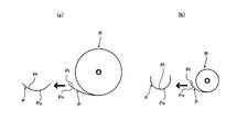
- FIG. 1 is a diagram for explaining curling of a paper portion drawn from roll paper
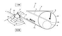
- FIG. 2 is a technique for correcting curling of the paper portion P in the paper transport mechanism 10 of the present invention. It is a figure which shows an idea notionally.
- the roll paper R is wound in a roll shape with one side of the long paper facing inside and the other side facing outside.
- the surface on one side of the sheet or sheet portion P may be referred to as an inner surface Pi
- the surface on the other side may be referred to as an outer surface Po.
- the paper portion P wound in a roll shape is curled and pulled out from the roll paper R, and as shown by the arrows in the figure, the paper portion P cut into a predetermined length has the inner surface Pi side inward. Will curl up.
- FIG. 1B As shown in FIG. 1B, as the roll diameter of the roll paper R becomes smaller, the curl becomes stronger and the degree to which the cut paper portion P is rounded becomes larger.
- the paper transport mechanism 10 of the present invention includes an ironing part S, an upstream pressing part F1, a downstream pressing part F2, and an arm member 6.
- the paper portion P is conveyed obliquely upward and leftward from the roll paper R, as indicated by the thin straight arrow.
- the upstream presser portion F1, the ironing portion S, and the downstream presser portion F2 are arranged in the order of description from the upstream side in the transport direction.
- the ironing portion S is in contact with the outer surface Po of the paper portion P.
- the inner surface Pi side may be referred to as one side
- the outer surface Po side may be referred to as the other side.
- the upstream side presser portion F1 is disposed upstream of the ironing portion S in the transport direction, and presses the paper portion P from one side.
- the downstream presser portion F2 is disposed downstream of the ironing portion S in the transport direction, and presses the paper portion P from one side.
- the upstream side presser part F1 and the downstream side presser part F2 correspond to an example of the presser part in the present invention.
- the presser portion in the present invention may be configured by either one of the upstream presser portion F1 and the downstream presser portion F2.
- the arm member 6 operates following the change of the roll diameter of the roll paper R.
- the mode in which the arm member 6 operates is not limited, in FIG. 2, the one end side comes into contact with the outer peripheral surface R1 of the roll paper R, and as shown by the arc-shaped arrow, the one end side becomes smaller as the roll diameter decreases.
- the mode which rotates below is illustrated.
- the upstream presser part F1 is interlocked with the operation of the arm member 6 by a not-shown interlocking mechanism.
- the upstream presser part F1 It moves from one side to the other side in conjunction with the arm member 6.
- the downstream presser portion F2 may be linked to the arm member 6 or the upstream presser portion F1 and the downstream presser portion F2 may be linked to the arm member 6. It is good.
- the sheet portion P is bent at a predetermined angle at a portion that contacts the ironing portion S by the ironing portion S, the upstream holding portion F1, and the downstream holding portion F2.
- the bending angle corresponds to an inner angle in the present invention, and the other surface of the paper portion P that is upstream from the ironing portion S and the other side of the paper portion P that is downstream from the ironing portion S. It is the angle sandwiched between the two surfaces.
- an angle corresponding to the inner angle in the present invention is referred to as a squeezing angle ⁇ .
- the upstream presser portion F1 is interlocked with the arm member 6 from one side by an interlocking mechanism (not shown). Move towards the other side. Thereby, as shown with a dashed-two dotted line, the ironing angle (alpha) becomes small and correction force can be enlarged. Further, in conjunction with the arm member 6, the downstream pressing portion F2 may be moved from one side to the other side to reduce the ironing angle ⁇ as indicated by the alternate long and short dash line.
- Both side pressing portions F2 may be moved from one side toward the other side, and the ironing angle ⁇ may be further reduced as indicated by a two-dot chain line and a one-dot chain line. Further, the ironing portion S is urged from the other side to the one side, the roll diameter of the roll paper R is reduced, and the tension in the transport direction applied to the paper portion P when the paper portion P is pulled in the transport direction is also increased. When it becomes small, you may employ
- the correction force can be increased by reducing the squeezing angle ⁇ , and the correction force is increased according to the strength of the curl of the paper portion P.
- the correction force varies depending on the radius of the ironing portion S, and the correction force increases as the radius of the ironing portion S decreases. Further, the correction force varies depending on the speed (conveyance speed) at which the paper portion P is conveyed, and the correction force increases as the conveyance speed decreases. For these reasons, in addition to the adjustment of the ironing angle ⁇ described above, the correction force can be adjusted by combining the setting of the radius of the ironing portion S and the adjustment of the conveyance speed.
- the present invention is applied to a printer will be described based on the concept of the present invention described with reference to FIGS. 1 and 2.
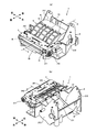
- FIG. 3A is a perspective view of the printer 1 according to an embodiment of the present invention as viewed from diagonally upward on the front right side
- FIG. 3B shows the printer 1 shown in FIG. It is the perspective view seen from the left diagonal upper direction.
- the printer 1 is covered with, for example, a casing made up of a main body case, a rear cover, and a front cover, but FIG. 3 shows an internal structure in which the casing is omitted.
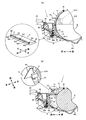
- 4A is a cross-sectional view taken along the line AA of the printer 1 shown in FIG. 3A
- FIG. 4B is a cross-sectional view taken along the line BB of the printer 1 shown in FIG. 3B.
- the printer 1 shown in FIGS. 3 and 4 accommodates a roll paper R in which a long heat-sensitive paper is wound in a roll shape, and prints on the paper while pulling out the paper portion of the accommodated roll paper R from the lower side. And a thermal printer that cuts the printed paper.
- 3A and 4A show a state in which the roll paper R is stored
- FIGS. 3B and 4B show a state in which the roll paper R is removed.
- 3A and 4A the diagonally lower left is the front (front side) and the diagonally upper right is the rear (back side).
- the upper left is the front (front side)
- the lower right is the back (back side).
- directions such as front, rear, left and right may be used with reference to the state where each component is assembled to the printer 1.
- the printer 1 includes a paper holder 2 and a platen holder 3.
- the paper holder 2 includes a storage portion 21 that stores the roll paper R, and the storage portion 21 includes a support portion 211 that supports the roll paper R and a pair of side wall portions 212 and 212.
- the paper holder 2 is provided with a print head 22.
- the platen holder 3 constitutes a part of a rear cover (not shown). As shown in FIG. 4, the platen holder 3 includes a platen roller 31, an upstream guide member 32, a downstream guide member 33, and an arm. A member 6 is attached.
- the roll paper R is set in the storage unit 21 with a rear cover (not shown) opened.
- the paper portion P drawn from the roll paper R is indicated by a broken line, and the leading end of the paper portion P drawn from the roll paper R in FIG. Is the sheet conveyance path, and the direction from the accommodating portion 21 toward the leading edge of the sheet portion P corresponds to the conveyance direction in the present invention.
- a paper discharge port (not shown) formed by a rear cover and a front cover is formed in the vicinity of the leading end portion of the paper portion P. That is, the path from the roll paper R to the paper discharge port is a paper conveyance route, and the direction from the storage unit 21 toward the paper discharge port corresponds to the conveyance direction in the present invention.
- the decal member 5 includes a base portion 51 that extends in the left-right direction and is fixed to the paper holder 2, and a rib that protrudes upward from the base portion 51. 52.
- the rib 52 extends in the left-right direction in the same manner as the base portion 51.
- the base portion 51 and the rib 52 are reinforced at a predetermined interval in the left-right direction.
- a part 521 is provided.
- a squeezed portion S is provided at the tip portion of the rib 52.
- the platen roller 31 extends in the left-right direction and is disposed so as to face the print head 22.
- the platen roller 31 is provided with a platen gear 311 for transmitting the rotational force generated by a not-shown transport motor to the platen roller 31.
- a cutter unit 23 and a fixed blade 35 described later with reference to FIG. 5 are provided on the downstream side of the platen roller 31 and the print head 22 in the transport direction.
- the front end portion of the paper portion P of the roll paper R is attached to the printer 1 before the rear cover is closed. Pull out to the outside.
- the platen roller 31 comes into contact with the print head 22 with an appropriate pressure.
- the paper portion P drawn from the roll paper R is sandwiched between the platen roller 31 and the print head 22.
- the sandwiched paper portion P is transported in the transport direction by the frictional action between the platen roller 31 and the print head 22 as the platen roller 31 rotates.
- the sheet portion P can be back-fed upstream in the transport direction by reversing the platen roller 31. Further, printing is performed on the paper portion P by the print head 22, and the cutter unit 23 (see FIG. 5 and the like) is driven to cut the paper portion P into a predetermined length.
- a downstream guide member 33 is provided on the upstream side in the transport direction of the platen roller 31.
- the downstream guide member 33 has a downstream pressing portion F2 shown in FIG. 2, and in the present embodiment, the downstream guide member 33 is fixed to the platen holder 3.
- An upstream guide member 32 is provided on the upstream side in the transport direction of the downstream guide member 33.
- the upstream guide member 32 has an upstream pressing portion F1 shown in FIG.
- the upstream guide member 32 is rotatably attached to a shaft body 34 extending in the left-right direction. Thereby, the upstream guide member 32 can rotate around the shaft body 34. Further, the arm member 6 is also rotatably attached to the shaft body 34.
- the arm member 6 is a plate-like member that is curved in an arc shape in the front-rear direction and provided with lattice-like reinforcing ribs on the surface, and on the other end side portion with respect to one end side attached to the shaft body 34, A contact roller 61 is provided.
- the shaft body 34 is provided with three torsion springs arranged in the left-right direction while being inserted through the shaft body 34. Among these three torsion springs, the torsion spring disposed at the center in the left-right direction is referred to as a first torsion spring 341, and the two torsion springs disposed on both sides in the left-right direction are referred to as second torsion springs 342.
- the upstream guide member 32 is biased counterclockwise about the shaft body 34 by the first torsion spring 341 when viewed from the left side. That is, the upstream presser portion F1 is urged toward one side in FIG. As a result, the upstream presser portion F1 is biased in a direction away from the paper portion P.
- the arm member 6 is urged clockwise around the shaft body 34 by the two second torsion springs 342 when viewed from the left side, and the contact roller 61 abuts on the outer peripheral surface R1 of the roll paper R. Yes.
- the arm member 6 Even if the roll diameter of the roll paper R changes, the arm member 6 maintains the state in which the contact roller 61 is in contact with the outer peripheral surface R1 of the roll paper R, and follows the change in the roll diameter of the roll paper R. When viewed from above, the arm member 6 rotates clockwise.
- FIG. 5 is a diagram for explaining a state in which the arm member 6 rotates clockwise in accordance with a change in the roll diameter of the roll paper R.
- the ironing angle ⁇ does not change.
- FIG. 6 is a diagram for explaining how the ironing angle ⁇ of the paper portion P changes as the roll diameter of the roll paper R changes.
- 5 and 6 show the printer 1 shown in FIG. 4A viewed from the left side.
- the rotation direction and the urging direction of the upstream guide member 32 and the arm member 6 will be described with reference to the direction viewed from the left side.
- 5 and FIG. 6 show how the roll diameter of the roll paper R becomes smaller in stages, and the paper portion P is shown by a broken line so that it can be easily distinguished from the members of the printer 1.
- FIG 5 and 6 show the cutter unit 23 and the fixed blade 35 provided on the downstream side of the platen roller 31 and the print head 22 in the transport direction.
- the cutter unit 23 has a movable blade 231 and reciprocates the movable blade 231 with respect to the fixed blade 35.
- the direction from the roll paper R toward the paper discharge port is the transport direction.
- the arm member 6 rotates clockwise around the shaft body 34 as the roll diameter of the roll paper R decreases, the arm member 6 eventually engages with the upstream guide member 32, When the arm member 6 is further rotated clockwise, the upstream guide member 32 is rotated clockwise against the urging force of the first torsion spring 341 (see FIG. 4 and the like) in conjunction with the arm member 6. .
- FIG. 5A the state before the arm member 6 engages with the upstream guide member 32 is shown by enlarging it with a circle.
- FIG. 5B the arm member 6 is connected to the upstream guide member 32. Engagement is shown encircled with a circle.
- the upstream guide member 32 has an engaged portion 321 on the shaft body 34 side, and the arm member 6 is an upstream guide member. It has the engaging part 62 engaged with the to-be-engaged part 321 of 32. Further, a stopper 323 is provided on the front side portion of the upstream guide member 32.
- FIG. 5A shows a state in which the roll diameter of the roll paper R is maximum.
- the engaging portion 62 of the arm member 6 is engaged with the engaged portion 321 of the upstream guide member 32. Not done.
- the upstream guide member 32 is biased counterclockwise by the first torsion spring 341 (see FIG. 4), and the first presser portion F1 is separated from the paper portion P.
- the paper portion P drawn from the roll paper R is bent at the ironing portion S of the decurling member 5 and pressed from the one side by the second pressing portion F2 of the downstream guide member 33, and then the platen roller 31 and It is sandwiched between the print heads 22.
- the ironing angle ⁇ 1 of the paper portion P is preferably in the range of about 110 to 120 degrees. If the squeezing angle ⁇ 1 exceeds 120 degrees, the correction force tends to be insufficient, and if the squeezing angle ⁇ 1 is less than 110 degrees, the correction force becomes too strong and reverse curling occurs. There is a tendency to end up. 5 and 6 schematically show the ironing angle ⁇ shown in the figure does not necessarily match the preferred angle in the present invention. In this state, when the paper portion P is transported in the transport direction, a correction force corresponding to the ironing angle ⁇ 1 is applied to the paper portion P by the ironing portion S.
- the engaging portion 62 of the arm member 6 When the arm member 6 is rotated clockwise as the roll diameter of the roll paper R is reduced, the engaging portion 62 of the arm member 6 is connected to the upstream guide member 32 as shown in FIG. Engage with the engaged portion 321.
- the roll diameter of the roll paper R when the engaging portion 62 of the arm member 6 is engaged with the engaged portion 321 of the upstream guide member 32 shown in FIG. 5B is referred to as an upper limit set value.
- the state where the first presser portion F1 is separated from the paper portion P continues.
- the arm member 6 When the roll diameter of the roll paper R further decreases, the arm member 6 further rotates clockwise, and the upstream guide member 32 engaged with the arm member 6 also rotates clockwise in conjunction with the arm member 6. To do. Thereby, as shown in FIG. 6A, the first pressing portion F ⁇ b> 1 of the upstream guide member 32 contacts the inner surface Pi of the paper portion P.
- the roll diameter of the roll paper R when the first pressing portion F1 of the upstream guide member 32 shown in FIG. 6A contacts the inner surface Pi of the paper portion P is referred to as a contact set value.
- the position of the roll paper R slightly changes due to the inclination of the support portion 211 of the accommodating portion 21. From the state shown in FIG. In the period up to the contact set value shown in a), the ironing angle ⁇ 1 is substantially constant and does not change. However, in the state where the roll diameter is the maximum and the roll diameter is the upper limit set value, the first pressing portion F1 of the upstream guide member 32 is not in contact with the inner surface Pi of the paper portion P, and the paper portion P Is supported at two points, the second pressing portion F2 of the downstream guide member 33 and the ironing portion S of the decurling member 5.
- the first pressing portion F1 of the upstream guide member 32 contacts the inner surface Pi of the paper portion P, and the paper portion P is the second pressing portion of the downstream guide member 33. It is supported at three points: F2, the ironing portion S of the decurling member 5, and the first pressing portion F1 of the upstream guide member 32. For this reason, even if the size of the squeezing angle ⁇ 1 does not change, the paper portion P is supported at two points. In the state where the roll diameter is supported by the contact set value, the correction force becomes stronger.
- the correction force can be adjusted by changing the number of fulcrums supporting the paper portion P in addition to the adjustment of the correction force due to the change in the size of the ironing angle ⁇ .
- the first pressing portion F1 of the upstream guide member 32 shown in FIG. A certain amount of play is provided until the state of contact with the inner surface Pi. For this reason, even if the position where the arm member 6 and the upstream guide member 32 are engaged varies somewhat, the position where the first pressing portion F1 of the upstream guide member 32 contacts the inner surface Pi of the paper portion P, that is, the start of ironing. It becomes easy to set the angle aimed at the position.
- the upper limit of the roll diameter that needs to be corrected is set as an upper limit set value, for example, and during the period when the roll diameter is larger than the upper limit set value, the movement of the first presser portion F1 is stopped and the roll diameter becomes smaller.
- the correction force applied to the paper portion P may not be increased until the upper limit set value is reached.
- the upstream guide member 32 is also rotated clockwise in conjunction with the arm member 6, and the inner surface Pi of the paper portion P is moved by the first pressing portion F 1 of the upstream guide member 32. Pressed. That is, the paper portion P is pressed from one side (see FIG. 2) by the first pressing portion F1. As a result, the ironing angle ⁇ is reduced and the correction force applied to the paper portion P by the ironing portion S is increased.
- the upstream guide member 32 also rotates clockwise in conjunction with the arm member 6 so that the ironing angle ⁇ becomes smaller.
- the stopper 323 of the upstream guide member 32 comes into contact with the downstream guide member 33, and the rotation of the upstream guide member 32 and the arm member 6 stops.
- the roll diameter of the roll paper R at the time when the rotation of the upstream guide member 32 and the arm member 6 stops after contacting the downstream guide member 33 shown in FIG. 6B is referred to as a lower limit set value. In the period from the contact setting value shown in FIG. 6A to the lower limit setting value shown in FIG.
- the ironing angle ⁇ 1 decreases from the ironing angle ⁇ 1 to the ironing angle ⁇ 2 as the roll diameter decreases.
- the correction force applied to the paper portion P increases.
- the ironing angle ⁇ 2 of the paper portion P is preferably in the range of about 80 to 90 degrees. If the squeezing angle ⁇ 2 exceeds 90 degrees, the correction force may be insufficient, and if the squeezing angle ⁇ 2 is less than 80 degrees, the correction force may be too strong.
- the downstream side guide member 33 Since the downstream side guide member 33 is fixed to the platen holder 3 (see FIG. 4), the upstream side guide member 32 and the arm member 6 are blocked by the downstream side guide member 33, and FIG. It does not rotate clockwise as compared to the state shown. For this reason, the ironing angle ⁇ 2 in the state of the lower limit set value becomes the smallest, and even if the roll diameter of the roll paper R is further reduced from the lower limit set value as shown in FIG. Will not change. That is, the ironing angle ⁇ 2 does not change during the period less than the lower limit set value shown in FIG. 6B, and as a result, the correction force applied to the paper portion P by the ironing portion S becomes constant. In the paper portion P, the curl becomes stronger as the roll diameter becomes smaller.
- the ironing angle ⁇ is made too small, problems such as excessive frictional load on the paper portion P may occur. Further, the correction force may be applied more than necessary, and reverse curling may occur in the paper portion P.
- the lower limit set value is set, and when the roll diameter becomes equal to or smaller than the lower limit set value, the movement of the first presser portion F1 is stopped, thereby preventing problems such as an excessive friction load being applied to the paper portion P. In addition, the occurrence of reverse curl is also suppressed.
- the squeezing angle ⁇ may be adjusted according to the waist and thickness of the paper, the basis weight, or environmental conditions such as temperature and humidity.
- conveyance of the paper portion P, printing on the paper portion P, and the like are controlled by a printer control unit 70 configured by a microcomputer.
- FIG. 7 is a block diagram showing a circuit configuration of the printer 1 shown in FIG.
- a printer control unit 70 is provided in the printer 1 shown in FIG. 3 as shown in FIG.
- a platen control circuit 74, a print head control circuit 75, a cutter control circuit 76, and a roll diameter sensor 77 are connected to the printer control unit 70.
- the printer control unit 70 includes a CPU 71, a RAM 72, and a ROM 73.
- the ROM 73 stores various programs such as a platen control program for controlling the platen control circuit 74, a print head control program for controlling the print head control circuit 75, and a cutter control program for controlling the cutter control circuit 76. Further, the ROM 73 stores correspondence data between the roll diameter of the roll paper R and the rotation speed of the platen roller 31 in the forward rotation direction.
- the rotational speed of the platen roller 31 with respect to the roll diameter of the roll paper R is obtained in advance as a test, and the roll diameter of the roll paper R and the rotational speed of the platen roller 31 are determined on a one-to-one basis.
- the correspondence data is set such that, for example, when the roll diameter of the roll paper R becomes smaller, the rotation speed of the platen roller 31 in the forward rotation direction decreases and the conveyance speed of the paper portion P becomes slower.
- the rotation speed of the platen roller 31 may be obtained by calculation based on the roll diameter of the roll paper R.
- the platen control circuit 74 is connected to a transport motor (not shown) that rotates the platen roller 31.
- the print head control circuit 75 is connected to the print head 22 shown in FIG. 5, and the cutter control circuit 76 is connected to the cutter unit 23 also shown in FIG.
- the platen control circuit 74 drives the carry motor according to the control of the CPU 71 based on the platen control program, and rotates the carry motor forward or backward.
- the platen roller 31 also rotates in the forward direction, whereby the paper portion P is transported in the transport direction.
- the conveyance motor is reversed
- the platen roller 31 is also reversed, whereby the sheet portion P is back-fed in the direction opposite to the conveyance direction.
- the print head control circuit 75 causes the print head 22 to perform a printing operation on the paper portion P according to the control of the CPU 71 based on the print head control program.
- the print head 22 performs printing on the paper portion P in contact with the heat generating elements by selectively causing the heat generating elements to generate heat according to the control of the CPU 71.
- the cutter control circuit 76 drives the movable blade 231 of the cutter unit 23 according to the control of the CPU 71 based on the cutter control program.
- the movable blade 231 is driven, the paper portion P is cut by the movable blade 231 and the fixed blade 35.
- the roll diameter sensor 77 detects the roll diameter of the roll paper R.
- a reflection type sensor (not shown) provided on the side wall portion 212 of the accommodating portion 21 shown in FIG.
- a mechanical switch or the like may be used instead of the reflective sensor.
- This main program starts when the printer 1 is turned on.
- the CPU 71 of the printer control unit 70 determines that a print command has been generated, the CPU 71 drives the carry motor to start the rotation of the platen roller 31 and starts printing on the paper portion P by the print head 22.
- the platen roller 31 rotates, the paper portion P is transported in the transport direction, and the curl is corrected by being squeezed by the squeezing unit S.
- the roll diameter of the roll paper R is equal to or smaller than the contact set value shown in FIG. 6A, and the roll diameter becomes smaller during the period equal to or greater than the lower limit set value shown in FIG.
- the ironing angle ⁇ becomes smaller, and the correction force becomes stronger.
- the CPU 71 drives the transport motor so that the rotation of the platen roller 31 becomes the rotation speed determined by the corresponding data based on the roll diameter of the roll paper R measured by the roll diameter sensor 77. .
- the conveying speed is reduced and the correction force is increased.
- the correction force can be adjusted according to the strength of the curl of the paper portion P.
- the CPU 71 stops the conveyance of the paper portion P.
- the CPU 71 drives the movable blade 231 of the cutter unit 23. Thereby, the paper portion P is cut into a predetermined length.
- the CPU 71 drives the conveyance motor and reverses the platen roller 31 to back-feed the paper portion P. Note that the CPU 71 may back-feed the paper portion P every time the paper portion P is cut.
- FIG. 8A is an enlarged view of a portion A surrounded by a circle in FIG. 6B, and FIG. 8B is a back-feed state of the paper portion shown in FIG. FIG.
- an accommodation area A is provided above the ironing part S in the decurling member 5, that is, on the opposite side of the paper part P from the ironing part S. ing.
- FIGS. 9 and 10 are diagrams showing a first modified example in which the configuration of the printer 1 shown in FIGS. 5 and 6 is different, and the roll diameter of the roll paper R is gradually increased from FIGS. 9A to 10B. It shows how it gets smaller.
- the decal member 5 includes a damper 53 and a shaft 54 having an ironing portion S.
- the damper 53 is provided with a spring 533.
- FIG. 9A a state in which the damper 53 and the shaft 54 are viewed obliquely from the left front is shown by enlarging them with a circle.
- the damper 53 is a plate-like member that is long in the left-right direction.
- the upper end side portion on the downstream side (front side) in the transport direction is provided with claw portions 532 at three positions in the left-right direction, both end portions and the center portion, A notch 531 is formed between the tabs 532.
- the shaft 54 is made of metal, and in this embodiment, a shaft having a diameter of about 2 mm is adopted. Further, a reduced diameter portion 541 having a diameter reduced to about 1.7 mm is formed at a portion of the shaft 54 corresponding to the claw portion 532.
- the shaft 54 is rotatably attached to the damper 53 by having the reduced diameter portion 541 fitted into the claw portion 532.
- the shaft 54 may be fixed to both ends of the damper 53 in the left-right direction by E-rings or the like.
- a damper installation portion 2111 is provided on the downstream side of the support portion 211 in the transport direction, and the damper 53 has a damper installation portion formed by a hinge member (not shown) whose end on the upstream side in the transport direction extends in a direction perpendicular to the paper surface. 2111 is attached. Thereby, the damper 53 is provided in the damper installation part 2111 so that rotation is possible. Further, a spring accommodating portion 2112 is provided on the downstream side in the transport direction with respect to the damper installation portion 2111, and the spring 533 is accommodated in the spring accommodating portion 2112. The damper 53 is biased toward one side (see FIG. 2) by a spring 533, and the shaft 54 having the ironing portion S is also biased toward one side (see FIG. 2).
- the damper 53 sinks according to the tension in the transport direction applied to the paper portion P. That is, when the roll diameter is large and the conveyance direction tension applied to the paper portion P is strong, the damper 53 sinks greatly, while the roll diameter becomes small and the conveyance direction tension applied to the paper portion P decreases. The amount that the damper 53 sinks decreases. Accordingly, the size of the ironing angle ⁇ can be adjusted according to the size of the roll diameter. In addition, when the roll diameter of the roll paper R is large or when the conveyance is started, the conveyance load is reduced, so that deterioration of the platen roller 31 and drive system components, the load applied to the conveyance motor, and the like can be reduced. Further, since the shaft 54 is rotatable with respect to the damper 53, wear of the shaft 54 can be suppressed and the frictional load on the paper portion P can be reduced.
- a sensor substrate 2121 is provided at the upper end portion of the left side wall portion 212, and two roll diameter sensors 77, 77 are provided on the substrate 2121.
- the substrate 2121 is attached to the side wall portion 212 such that the roll diameter sensors 77 and 77 are located outside the side wall portion 212 in the left-right direction. Thereby, interference with the roll diameter sensors 77 and 77 and the roll paper R is prevented.
- These roll diameter sensors 77 and 77 are constituted by transmission type sensors, and a shield plate 63 capable of shielding between the projector and the light receiver in the roll diameter sensors 77 and 77 is provided on the right edge portion of the arm member 6. It has been.
- FIG. 9A shows a state in which the roll diameter of the roll paper R is maximum, and the upstream presser portion F1 of the upstream guide member 32 is not in contact with the paper portion P. Further, when the paper portion P is transported in the transport direction, the back tension due to the weight of the roll paper R applies a strong tension in the transport direction to the paper portion P, so that the damper 53 sinks greatly and the ironing angle ⁇ increases. As a result, the correction force applied to the paper portion P is reduced. Further, the two roll diameter sensors 77 do not detect the shielding plate 63, and the conveyance speed of the paper portion P does not change.
- the arm member 6 engages with the upstream guide member 32 as the roll diameter of the roll paper R becomes smaller.
- the upstream guide member 32 is interlocked with the arm member 6, and the first pressing portion F ⁇ b> 1 of the upstream guide member 32 comes into contact with the inner surface Pi of the paper portion P.
- the tension in the transport direction applied to the paper portion P is weakened compared to the state shown in FIG.
- the amount of sinking decreases.
- the ironing angle ⁇ becomes smaller and the correction force applied to the paper portion P becomes stronger.
- the shielding plate 63 of the arm member 6 is in a state of shielding the detection area of the roll diameter sensor 77 on one side.
- FIG. 9B a state in which the shielding plate 63 of the arm member 6 shields the detection region of the roll diameter sensor 77 on one side is shown by encircled with a perspective view seen from the diagonally left rear.
- the first pressing portion F1 of the upstream guide member 32 presses the inner surface Pi of the paper portion P from one side (see FIG. 2).
- the amount by which the damper 53 sinks when the paper portion P is conveyed is further reduced.
- the ironing angle ⁇ becomes smaller and the correction force applied to the paper portion P becomes stronger. Note that since the state detected only by the roll diameter sensor 77 on one side does not change, the conveyance speed of the paper portion P does not change.
- the first pressing portion F1 of the upstream guide member 32 presses the inner surface Pi of the paper portion P from one side (see FIG. 2).
- the amount increases, and the stopper 323 of the upstream guide member 32 contacts the downstream guide member 33.
- the squeezing angle ⁇ becomes smaller and the correction force becomes stronger than in the state shown in FIG.
- the shielding plate 63 of the arm member 6 shields the detection areas of the two roll diameter sensors 77 and 77, and both roll diameter sensors 77 are in the detection state.
- the conveyance speed of the paper portion P is further reduced, and the correction force applied to the paper portion P is further increased.
- the conveyance speed of the paper portion P is changed in three ways using two roll diameter sensors 77, but the conveyance speed is changed in two ways using one roll diameter sensor 77.
- three or more roll diameter sensors 77 may be used to change the transport speed to four or more.
- FIG. 11 is a view showing a second modified example in which the configuration of the spring accommodating portion 2112 shown in FIGS. 9 and 10 is different.
- the spring accommodating portion 2112 of the second modified example has a wall portion 2112a and a spring receiving bottom portion 2112b.
- the spring receiving bottom portion 2112b is a portion that receives the spring 533, and is rotatably attached to the lower end portion of the wall portion 2112a by a hinge member 2112c extending in a direction orthogonal to the paper surface.
- the hinge member 2112c as an axis, the upstream portion of the spring receiving bottom 2112b in the transport direction is rotated clockwise as indicated by a thick arc-shaped arrow in the figure. It can be rotated.
- the ironing angle ⁇ in the state shown in FIG. 11A is about 90 degrees
- the ironing angle ⁇ in the state shown in FIG. 11B is as large as about 115 degrees.
- the thickness of the paper sheet is adjusted by moving the position of the lower end of the spring 533 downward together with the adjustment of the correction force according to the roll diameter of the roll paper R.
- the type of paper, or the degree of curling depending on the usage environment such as temperature and humidity, etc., the correction force can be adjusted more finely.
- the rotation of the spring receiving bottom 2112b may be performed manually by providing a manual lever or the like, or a mode of rotating by a solenoid or the like may be employed.
- the curl of the paper portion drawn from the roll paper can be corrected according to the strength of the curl.
- the present invention is not limited to the above-described embodiment, and various modifications can be made within the scope described in the claims.
- a mode in which the paper portion P is pulled out from the lower side of the roll paper R is described as an example.
- the paper portion P is pulled out from the upper side of the roll paper R and, for example, ironed downward.
- a mode of energizing the part S may be adopted.
- the mode including the upstream side presser portion F1 and the downstream side presser portion F2 has been described as an example, but the mode including only one of the modes may be provided.
- the upstream side pressing portion F1 and the downstream side pressing portion F2 may also be configured by a rotatable shaft.
Landscapes
- Registering, Tensioning, Guiding Webs, And Rollers Therefor (AREA)
- Handling Of Continuous Sheets Of Paper (AREA)
- Controlling Rewinding, Feeding, Winding, Or Abnormalities Of Webs (AREA)
Abstract
ロール紙から引き出された用紙部分の巻き癖を、その強さに応じて矯正することができる用紙搬送機構を提供する。長尺の用紙がロール状に巻かれたロール紙(R)から用紙部分を搬送する用紙搬送機構(1)において、通過する用紙部分(P)の外面(Po)に接し、用紙部分(P)の巻き癖を矯正するしごき部(S)と、用紙部分(P)を一方側から押さえ、しごき部(S)で用紙部分(P)を屈曲させる押え部と、ロール紙(R)の外周面(R1)に当接しロール紙(R)のロール径の変化に追従して動作するアーム部材(6)とを備え、上流側押え部(F1)は、アーム部材(6)が動作している期間のうちの少なくとも一部の期間で、ロール径が小さくなるにつれてしごき部(S)で屈曲した状態の用紙部分(R)のしごき角αの大きさも小さくなるように、一方側から他方側に向かって、アーム部材(6)に連動して移動するものである。
Description
本発明は、ロール紙から用紙部分を搬送する用紙搬送機構に関する。
長尺の用紙がロール状に巻かれたロール紙から用紙部分を搬送する用紙搬送機構が、プリンタやファクシミリ装置等に採用されている(例えば、特許文献1等参照)。特許文献1に記載された用紙搬送機構は、プラテンローラ、およびプラテンローラとロール紙との間に配置されたアイドラローラ等を有し、プラテンローラには、印字ヘッドが対向配置されている。特許文献1等に記載されたプリンタやファクシミリ装置等では一般的に、ロール紙をセットした後、セットしたロール紙から先頭部分を手で引き出し、先頭部分をプラテンローラと印字ヘッドの間に挿入させる。こうしておくことで、ロール紙から引き出された用紙部分は、プラテンローラが回転することによって所定の搬送方向に搬送される。なお、用紙部分は印字ヘッドによって印字が施された後、カッタによって切断されレシート等として排出される。
特許文献1に記載された用紙搬送機構に用いられるロール紙は、コンパクトで収納効率が高いが、その反面、ロール状に巻かれているため用紙部分に巻き癖(カール)がついてしまう。これにより、所定の長さに切断したレシート等が丸まってしまい、扱いにくく、見栄えが悪くなってしまう場合がある。このため、例えば、店舗等に設置される、クレジット決済用のレシートを発行するプリンタの場合には、客がレシートにサインをしやすいように、丸まってしまったレシートを店員が縦方向に半分に折って引っ張るなどして巻き癖を直してから、レシートを客に手渡すなどといった手間がかけられている。また、ロール紙は、ロール状に巻かれた用紙部分全てに一定の強さの巻き癖がついているわけではなく、ロール径によって巻き癖の強さが変化し、ロール径が小さくなるほど巻き癖が強くなる。このため、一定の力で巻き癖を矯正するだけでは、巻き癖の強さによって、矯正が不十分になったり、逆に、反対のカール(逆カール)がついてしまう場合がある。
本発明は上記事情に鑑み、ロール紙から引き出された用紙部分の巻き癖を、巻き癖の強さに応じて矯正することができる用紙搬送機構を提供することを目的とする。
上記目的を解決する本発明の用紙搬送機構は、長尺の用紙の一方側の面を内側にし他方側の面を外側にしてロール状に巻かれたロール紙から用紙部分を搬送する用紙搬送機構において、
通過する前記用紙部分の前記他方側の面に接し、該用紙部分の巻き癖を矯正するしごき部と、
前記用紙部分を前記一方側から押さえ、前記しごき部で該用紙部分を屈曲させる押え部と、
前記ロール紙の外周面に当接し該ロール紙のロール径の変化に追従して動作するアームとを備え、
前記押え部は、前記アームが動作している期間のうちの少なくとも一部の期間で、前記ロール径が小さくなるにつれて前記しごき部で屈曲した状態の用紙部分の内角の大きさも小さくなるように、前記一方側から前記他方側に向かって、該アームに連動して移動するものであることを特徴とする。
通過する前記用紙部分の前記他方側の面に接し、該用紙部分の巻き癖を矯正するしごき部と、
前記用紙部分を前記一方側から押さえ、前記しごき部で該用紙部分を屈曲させる押え部と、
前記ロール紙の外周面に当接し該ロール紙のロール径の変化に追従して動作するアームとを備え、
前記押え部は、前記アームが動作している期間のうちの少なくとも一部の期間で、前記ロール径が小さくなるにつれて前記しごき部で屈曲した状態の用紙部分の内角の大きさも小さくなるように、前記一方側から前記他方側に向かって、該アームに連動して移動するものであることを特徴とする。
ここで、内角とは、前記用紙部分の、前記しごき部よりも上流側となる前記他方側の面と、該用紙部分の、該しごき部よりも下流側となる該他方側の面とで挟まれた角度である。また、前記アームは、前記ロール径が所定範囲の径である場合に限って、前記ロール紙の外周面に当接し前記ロール径の変化に追従して動作するものであってもよい。例えば、前記アームは、前記ロール径が所定の径よりも小さくなると、動作を停止するものであってもよい。
本発明の用紙搬送機構では、前記用紙部分が、前記押え部によって前記一方側から押さえられながら前記しごき部によってしごかれる。前記押え部は、前記アームに連動して、前記ロール径が小さくなるにつれて前記内角の大きさが小さくなるように移動する。ここで、前記しごき部によってしごかれ、該用紙部分の巻き癖が矯正される力は、前記内角が小さくなるほど強くなる。以下、前記しごき部によって前記用紙部分をしごき、該用紙部分の巻き癖を矯正する力を、矯正力と称することがある。本発明の用紙搬送機構によれば、前記ロール径が小さくなり巻き癖が強くなるにつれて、前記内角を小さくし、前記矯正力を強くすることができる。これにより、前記用紙部分を巻き癖の強さに応じて矯正することができる。
また、本発明の用紙搬送機構において、前記押え部は、前記ロール径が上限設定値より大きい期間および該上限設定値より小さい下限設定値未満の期間では停止したものであり、該ロール径が該上限設定値以下であって且つ該下限設定値以上の期間では、該アームに連動して移動するものであることが好ましい。
前記ロール径が大きいほど巻き癖が弱くなるため、所定のロール径より大きくなると矯正する必要がないほど巻き癖が弱くなる場合がある。このため、例えば、矯正する必要があるロール径の上限を前記上限設定値に設定することで、該ロール径が該上限設定値より大きい期間では、前記押え部の移動を停止させ、前記用紙部分に必要以上に矯正力を付与しない態様とすることもできる。また、前記ロール径が小さくなるほど巻き癖が強くなるが、前記押え部を移動させ、前記内角を小さくしすぎると、用紙部分にかかる摩擦負荷が過大になる等の問題が生じる場合がある。このため、前記下限設定値を定め、前記ロール径が該下限設定値未満になると前記押え部の移動を停止させ、該ロール径が該下限値未満になっても一定の矯正力を付与する態様としてもよい。こうすることで、用紙部分に過大な摩擦負荷がかかってしまう等の問題を防止することができる。また、用紙部分に必要以上に矯正力を与えてしまい、用紙部分に逆カールが発生してしまうことも防ぐことができる。
さらに、本発明の用紙搬送機構において、前記押え部は、前記ロール径が前記上限設定値未満の接触設定値以下であって且つ前記下限設定値以上の期間を前記一部の期間として、前記ロール径が小さくなるにつれて前記内角の大きさも小さくなるように前記一方側から前記他方側に向けて移動するものであってもよい。
こうすることで、前記ロール径が前記接触設定値より大きく前記上限設定値以下の期間(以下、不変期間と称する。)では、前記押え部は、前記アームに連動して移動するが、該押え部が移動しても前記内角の大きさは変わらない。すなわち、上記不変期間では、前記押え部は、前記内角の大きさが小さくなるように移動することはない。
ここで、前記用紙部分の搬送が停止している待機状態では、該用紙部分が前記しごき部に接触しており、この状態が続くと該用紙部分における該しごき部に接触している箇所に屈曲癖がついてしまう場合がある。
そこで、本発明の搬送装置において、前記しごき部の、前記用紙部分を基準にして該しごき部とは反対側に設けられた、該用紙部分の一部を収容可能な収容領域と、前記用紙部分を搬送方向の下流側にバックフィードさせ前記収容領域に該用紙部分をループ化させるバックフィード手段とを備えた態様としてもよい。
前記バックフィード手段によって、前記収容領域に前記用紙部分をループ化させることで、該用紙部分にかかるテンションが開放され、該用紙部分が前記しごき部から離れるため、前記待機状態が続いても該用紙部分に屈曲癖がついてしまうことを防止できる。
ここで、前記用紙部分に付与される矯正力の強さは、前記用紙部分を搬送する搬送速度によって異なり、この搬送速度を遅くするほど相対的に矯正力が強くなる。
そこで、本発明の搬送装置において、前記用紙部分を搬送する搬送手段と、前記ロール紙のロール径を検知する検知手段と、前記搬送手段が前記用紙部分を搬送する搬送速度を前記検知手段で検知した前記ロール径に基づき制御する制御手段とを備え、前記制御手段は、前記ロール径が所定の大きさよりも小さくなると前記搬送速度を遅くするものであってもよい。
前記制御手段は、前記ロール径が小さくなるにつれて、前記搬送速度を連続的に遅くするものであってもよいし、該搬送速度を段階的に遅くするものであってもよい。
前記ロール径が所定の大きさよりも小さくなり巻き癖が強くなると前記搬送速度を遅くすることによって、前記用紙部分に付与される矯正力を大きくすることができる。
本発明の用紙搬送機構によれば、ロール紙から引き出された用紙部分の巻き癖を、巻き癖の強さに応じて矯正することができる。
以下、図面を参照して本発明の実施の形態を説明する。本発明の用紙搬送機構は、ロール紙から用紙部分を搬送する様々な機器に適用することができ、プリンタやファクシミリ装置はもちろん、印字や印刷等の機能を備えない機器にも適用することができる。初めに、本発明の用紙搬送機構の概念を図1および図2を用いて説明する。
図1は、ロール紙から引き出された用紙部分の巻き癖(カール)を説明するための図であり、図2は、本発明の用紙搬送機構10における、用紙部分Pの巻き癖を矯正する技術思想を概念的に示す図である。
図1(a)に示すように、ロール紙Rは、長尺の用紙の一方側の面を内側にし、他方側の面を外側にして、ロール状に巻かれたものである。以下、用紙あるいは用紙部分Pの一方側の面を内面Piと称することがあり、他方側の面を外面Poと称することがある。ロール状に巻かれた用紙部分Pには巻き癖がつき、ロール紙Rから引き出され、図の矢印で示すように、所定の長さに切断された用紙部分Pは、内面Pi側を内側にして丸まってしまう。また、図1(b)に示すように、ロール紙Rのロール径が小さくなると巻き癖が強くなり、切断された用紙部分Pが丸まる程度も大きくなる。
図2に示すように、本発明の用紙搬送機構10は、しごき部S、上流側押え部F1、下流側押え部F2、アーム部材6を備えるものである。また、図2では、細い直線の矢印で搬送方向を示すように、ロール紙Rから左斜め上方に用紙部分Pが搬送される。用紙部分Pが搬送される搬送経路には、搬送方向上流側から、上流側押え部F1、しごき部Sおよび下流側押え部F2が記載順に配置されている。しごき部Sは、用紙部分Pの外面Poに接している。以下、内面Pi側を一方側と称することがあり、外面Po側を他方側と称することがある。上流側押え部F1は、しごき部Sよりも搬送方向上流側に配置され、用紙部分Pを一方側から押さえるものである。また、下流側押え部F2は、しごき部Sよりも搬送方向下流側に配置され、用紙部分Pを一方側から押さえるものである。上流側押え部F1および下流側押え部F2は、本発明における押え部の一例に相当する。また、本発明における押え部は、上流側押え部F1および下流側押え部F2のうちのいずれか一方によって構成してもよい。
アーム部材6は、ロール紙Rのロール径の変化に追従して動作するものである。アーム部材6が動作する態様は限定されるものではないが、図2では、一端側がロール紙Rの外周面R1に当接し、円弧状の矢印で示すように、ロール径が小さくなるにつれて一端側が下方に回動する態様を例示している。上流側押え部F1は、不図示の連動機構によってアーム部材6の動作に連動するものであり、ロール紙Rのロール径が小さくなるにつれてアーム部材6が回動すると、上流側押え部F1は、アーム部材6に連動して一方側から他方側に向かって移動する。なお、上流側押え部F1に代えて、下流側押え部F2をアーム部材6に連動させる態様としてもよいし、上流側押え部F1と下流側押え部F2の双方をアーム部材6に連動させる態様としてもよい。
用紙部分Pは、しごき部S、上流側押え部F1および下流側押え部F2によって、しごき部Sに接触する部分で所定角度に屈曲する。この屈曲する角度は、本発明における内角に相当し、用紙部分Pの、しごき部Sよりも上流側となる他方側の面と、用紙部分Pの、しごき部Sよりも下流側となる他方側の面とで挟まれた角度である。以下、本発明における内角に相当する角度をしごき角αと称する。用紙部分Pがしごき角αに屈曲した状態でしごき部Sを通過すると、しごき部Sによって用紙部分Pがしごかれ、用紙部分Pの巻き癖を矯正することができる。しごき部Sにしごかれることによって用紙部分Pに付与される矯正力は、しごき角αによって異なり、しごき角αが小さくなるにつれて矯正力は大きくなる。
図2の二点鎖線で示すように、ロール紙Rのロール径が小さくなりアーム部材6が動作すると、上流側押え部F1は、不図示の連動機構によりアーム部材6に連動して一方側から他方側に向かって移動する。これにより、二点鎖線で示すように、しごき角αが小さくなり、矯正力を大きくすることができる。また、アーム部材6に連動して、下流側押え部F2を一方側から他方側に向かって移動させ、一点鎖線で示すようにしごき角αを小さくしてもよく、上流側押え部F1と下流側押え部F2の双方を一方側から他方側に向かって移動させ、二点鎖線および一点鎖線で示すようにしごき角αをより小さくしてもよい。さらに、しごき部Sを他方側から一方側に向けて付勢し、ロール紙Rのロール径が小さくなり、用紙部分Pが搬送方向に引っ張られた際に用紙部分Pにかかる搬送方向のテンションも小さくなると、しごき部Sが一方側に移動する態様を採用してもよい。これによって、破線で示すようにロール紙Rのロール径が小さくなるにつれてしごき角αをさらに小さくすることもできる。これらによって、ロール径が小さくなり用紙部分Pの巻き癖が強くなるほど、しごき角αを小さくすることで矯正力を大きくすることができ、用紙部分Pの巻き癖の強さに応じて矯正力を調整することができる。すなわち、上流側押え部F1および下流側押え部F2の少なくとも一方は、ロール紙Rのロール径が小さくなるにつれてしごき角も小さくなるように、一方側から他方側に向かって、アーム部材6に連動して移動するものである。
また、しごき部Sが円弧状のものである場合には、しごき部Sの半径の大きさによっても矯正力は異なり、しごき部Sの半径が小さくなるにつれて矯正力は大きくなる。さらに、用紙部分Pを搬送する速度(搬送速度)によっても、矯正力は異なり、搬送速度が遅くなるにつれて矯正力は大きくなる。これらのため、上述したしごき角αの調整と併せて、しごき部Sの半径の大きさの設定や、搬送速度の調整を組み合わせることによって、矯正力を調整することもできる。以下、図1および図2を用いて説明した本発明の概念を元に、本発明をプリンタに適用した一実施形態を説明する。
図3(a)は、本発明の一実施形態であるプリンタ1を、正面右斜め上方から見た斜視図であり、同図(b)は、同図(a)に示すプリンタ1を、背面左斜め上方から見た斜視図である。プリンタ1は、例えば、本体ケース、リヤーカバーおよびフロントカバーからなる筐体で覆われているが、図3では、筐体を省略した内部構造を示している。図4(a)は、図3(a)に示すプリンタ1のA-A断面図であり、図4(b)は、図3(b)に示すプリンタ1のB-B断面図である。
図3および図4に示すプリンタ1は、長尺の感熱式の用紙がロール状に巻かれたロール紙Rを収容し、収容したロール紙Rの用紙部分を下側から引き出しながらその用紙に印字を行い、印字された用紙を切断するサーマルプリンタである。図3(a)および図4(a)では、ロール紙Rを収納した状態を示し、図3(b)および図4(b)では、ロール紙Rを取り外した状態を示している。また、図3(a)および図4(a)では、左斜め下方が前(正面側)であり、右斜め上方が後ろ(背面側)である。図3(b)および図4(b)では、左斜め上方が前(正面側)であり、右斜め下方が後ろ(背面側)である。以下、各部品がプリンタ1に組み付けらた状態を基準にして前後左右などの方向を用いることがある。
図3および図4に示すように、プリンタ1は、ペーパーホルダ2と、プラテンホルダ3を備えている。ペーパーホルダ2は、ロール紙Rを収容する収容部21を有するものであり、収容部21は、ロール紙Rを支持する支持部211と、一対の側壁部212,212を有している。また、ペーパーホルダ2には、印字ヘッド22が設けられている。プラテンホルダ3は、不図示のリヤーカバーの一部を構成するものであり、プラテンホルダ3には、図4に示すように、プラテンローラ31、上流側ガイド部材32、下流側ガイド部材33およびアーム部材6が取り付けられている。本実施形態のプリンタ1では、不図示のリヤーカバーを開けた状態で、収容部21にロール紙Rをセットする。図3(a)および図4(a)では、ロール紙Rから引き出された用紙部分Pを破線で示しており、図4(a)における、ロール紙Rから引き出された用紙部分Pの先端までの経路が用紙搬送経路になり、収容部21から用紙部分Pの先端に向かう方向が、本発明における搬送方向に相当する。なお、用紙部分Pの先端部分付近には、不図示の、リヤーカバーとフロントカバーによって形成される用紙排出口が形成されている。すなわち、ロール紙Rから用紙排出口までの経路が用紙搬送経路になり、収容部21から用紙排出口に向かう方向が、本発明における搬送方向に相当する。
図4(a)に示すように、収容部21よりも搬送方向下流側部分には、図2に示すしごき部Sを有するデカール部材5が設けられている。図4(a)および同図(b)に示すように、デカール部材5は、左右方向に延在し、ペーパーホルダ2に固定されたベース部51と、このベース部51から上方に突出したリブ52を有している。このリブ52は、ベース部51と同様に左右方向に延在したものであり、図4(b)に示すように、ベース部51とリブ52には、左右方向に所定の間隔をあけて補強部521が設けられている。また、リブ52の先端部分にしごき部Sが設けられている。
プラテンローラ31は、左右方向に延在したものであり、印字ヘッド22に対して対向配置されている。また、プラテンローラ31には、不図示の搬送モータによって発生した回転力をプラテンローラ31に伝えるためのプラテンギヤ311が設けられている。さらに、プラテンローラ31および印字ヘッド22の搬送方向下流側には、図5を用いて後述する、カッタユニット23および固定刃35が設けられている。
本実施形態のプリンタ1では、不図示のリヤーカバーを開けた状態で収容部21にロール紙Rをセットした後、リヤーカバーを閉める前に、ロール紙Rの用紙部分Pの先端部をプリンタ1外部に引き出しておく。この状態でリヤーカバーを閉めると、プラテンローラ31が、印字ヘッド22に適宜な圧力で接触する。これにより、ロール紙Rから引き出された用紙部分Pがプラテンローラ31と印字ヘッド22によって挟み込まれる。挟み込まれた用紙部分Pは、プラテンローラ31が回転することによって、プラテンローラ31と印字ヘッド22との摩擦作用により搬送方向に搬送される。なお、本実施形態では、プラテンローラ31を逆転させることによって、用紙部分Pを搬送方向上流側にバックフィードさせることもできる。また、印字ヘッド22によって、用紙部分Pに印字が施され、カッタユニット23(図5等参照)が駆動して用紙部分Pが所定長さに切断される。
プラテンローラ31の搬送方向上流側には、下流側ガイド部材33が設けられている。この下流側ガイド部材33は、図2に示す下流側押え部F2を有するものであり、本実施形態では、下流側ガイド部材33は、プラテンホルダ3に固定されている。下流側ガイド部材33の搬送方向上流側には、上流側ガイド部材32が設けられている。この上流側ガイド部材32は、図2に示す上流側押え部F1を有するものである。上流側ガイド部材32は、左右方向に延在した軸体34に回動自在に取り付けられている。これにより、上流側ガイド部材32は、軸体34を中心にして回動可能である。また、軸体34には、アーム部材6も回動可能に取り付けられている。アーム部材6は、前後方向に円弧状に湾曲し表面に格子状の補強リブが設けられた板状のものであり、軸体34に取付けられた一端側に対し、他端側部分には、接触ローラ61が設けられている。また、軸体34には、軸体34にそれぞれ挿通された状態で左右方向に並べて配置された3つのトーションばねが設けられている。これら3つのトーションばねのうち、左右方向中央に配置されたトーションばねを第1トーションばね341と称し、左右方向両側に配置された2つのトーションばねそれぞれを第2トーションばね342と称する。上流側ガイド部材32は、左側から見た場合に、第1トーションばね341によって軸体34を中心に反時計回りに付勢されている。すなわち、上流側押え部F1が、図2における一方側に向けて付勢されている。これにより、上流側押え部F1は、用紙部分Pから離れる方向に付勢されている。一方、アーム部材6は、左側から見た場合に、2つの第2トーションばね342によって軸体34を中心に時計回りに付勢され、接触ローラ61がロール紙Rの外周面R1に当接している。アーム部材6は、ロール紙Rのロール径が変化しても接触ローラ61がロール紙Rの外周面R1に当接した状態が保たれ、ロール紙Rのロール径の変化に追従して、左側から見てアーム部材6が時計回りに回動する。
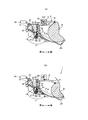
図5は、ロール紙Rのロール径の変化に伴いアーム部材6が時計回りに回動する様子を説明するための図であり、図5では、しごき角αは変化していない。また、図6は、ロール紙Rのロール径が変化することによって用紙部分Pのしごき角αが変化する様子を説明するための図である。図5および図6では、図4(a)に示すプリンタ1を左側から見た様子を示している。以下、上流側ガイド部材32およびアーム部材6の回動方向と付勢方向については、左側から見た方向を基準にして説明する。また、図5および図6では、ロール紙Rのロール径が小さくなっていく様子を段階的に示し、用紙部分Pは、プリンタ1の部材と区別しやすいように破線で示している。なお、図5および図6では、プラテンローラ31と印字ヘッド22の搬送方向下流側に設けられた、カッタユニット23および固定刃35を示している。なお、カッタユニット23は、可動刃231を有し、この可動刃231を固定刃35に対して往復動させるものである。
ロール紙Rから引き出された用紙部分Pが、プラテンローラ31と印字ヘッド22によって挟み込まれた後、カッタユニット23によって切断され、不図示の用紙排出口から排出されるまでが用紙部分Pの搬送経路になり、ロール紙Rから用紙排出口に向かう方向が搬送方向になる。前述したように、ロール紙Rのロール径が小さくなるにつれてアーム部材6が軸体34を軸として時計回りに回動していくと、やがてアーム部材6が上流側ガイド部材32に係合し、さらにアーム部材6が時計回りに回動すると、上流側ガイド部材32はアーム部材6に連動して、第1トーションばね341(図4等参照)の付勢力に抗して時計回りに回動する。
図5(a)では、アーム部材6が上流側ガイド部材32に係合する前の様子を円で囲んで拡大して示し、図5(b)では、アーム部材6が上流側ガイド部材32に係合した様子を円で囲んで拡大して示している。図5(a)および同図(b)で円で囲んで示すように、上流側ガイド部材32は、軸体34側に被係合部321を有し、アーム部材6は、上流側ガイド部材32の被係合部321に係合する係合部62を有している。また、上流側ガイド部材32の前側部分にはストッパ323が設けられている。
図5(a)では、ロール紙Rのロール径が最大の場合の様子を示し、この状態では、アーム部材6の係合部62は、上流側ガイド部材32の被係合部321に係合していない。このため、上流側ガイド部材32は、第1トーションばね341(図4参照)によって反時計回りに付勢され、第1押え部F1が用紙部分Pから離間した状態になっている。これにより、ロール紙Rから引き出された用紙部分Pは、デカール部材5のしごき部Sで屈曲し、下流側ガイド部材33の第2押え部F2によって一方側から押さえられた後、プラテンローラ31と印字ヘッド22によって挟み込まれている。ここで、用紙部分Pのしごき角α1は、110度~120度程度が好ましい範囲である。しごき角α1が120度を超えると、矯正力が不十分になってしまう傾向があり、しごき角α1が110度未満になると、矯正力が強くなりすぎて逆カールが生じてしまうといった問題が生じてしまう傾向がある。なお、図5および図6では、模式的に示しており、図に示すしごき角αの角度は、本発明における好ましい角度に必ずしも一致していない。この状態で、用紙部分Pが搬送方向に搬送されると、しごき部Sによって、しごき角α1に応じた矯正力が用紙部分Pに付与される。
ロール紙Rのロール径が小さくなるにつれてアーム部材6が時計回りに回動していくと、図5(b)に示すように、アーム部材6の係合部62は、上流側ガイド部材32の被係合部321に係合する。以下、図5(b)に示す、アーム部材6の係合部62が、上流側ガイド部材32の被係合部321に係合した時点におけるロール紙Rのロール径を、上限設定値と称する。ロール径が上限設定値になっても、第1押え部F1が用紙部分Pから離間した状態が継続する。
さらにロール紙Rのロール径が小さくなると、アーム部材6がさらに時計回りに回動し、このアーム部材6に係合した上流側ガイド部材32も、アーム部材6に連動して時計回りに回動する。これにより、図6(a)に示すように、上流側ガイド部材32の第1押え部F1が、用紙部分Pの内面Piに接触する。以下、図6(a)に示す、上流側ガイド部材32の第1押え部F1が、用紙部分Pの内面Piに接触した時点におけるロール紙Rのロール径を、接触設定値と称する。
ロール紙Rは、ロール径が小さくなっていくと収容部21の支持部211の傾斜等によって位置がやや変化するが、図5(a)に示す、ロール径が最大の状態から、図6(a)に示す接触設定値までの期間では、しごき角α1は略一定で変わらない。しかしながら、ロール径が最大の状態と、ロール径が上限設定値の状態においては、上流側ガイド部材32の第1押え部F1が、用紙部分Pの内面Piに接触しておらず、用紙部分Pは、下流側ガイド部材33の第2押え部F2と、デカール部材5のしごき部Sとの二点で支持されている。一方、ロール径が接触設定値の状態では、上流側ガイド部材32の第1押え部F1が、用紙部分Pの内面Piに接触し、用紙部分Pは、下流側ガイド部材33の第2押え部F2と、デカール部材5のしごき部Sと、上流側ガイド部材32の第1押え部F1の三点で支持されている。このため、しごき角α1の大きさは変わらなくても、用紙部分Pを二点で支持する、ロール径が最大の状態およびロール径が上限設定値の状態に比べて、用紙部分Pを三点で支持する、ロール径が接触設定値の状態の方が、矯正力が強くなる。このように、本実施形態においては、しごき角αの大きさの変化による矯正力の調整の他に、用紙部分Pを支持する支点数を変えることによっても矯正力を調整することができる。さらに、図5(b)に示す、アーム部材6と上流側ガイド部材32が係合した状態から、図6(a)に示す、上流側ガイド部材32の第1押え部F1が、用紙部分Pの内面Piに接触する状態までの間に、ある程度の遊びが設けられている。このため、アーム部材6と上流側ガイド部材32が係合する位置が多少ばらついても、上流側ガイド部材32の第1押え部F1が、用紙部分Pの内面Piに接触する位置、即ちしごき開始位置を狙った角度に設定することが容易になる。
また、用紙部分Pは、ロール径が大きいほど巻き癖が弱くなるため、所定のロール径より大きいとそれほど矯正する必要がない場合がある。このため、矯正する必要が生じるロール径の上限を、例えば上限設定値として設定し、ロール径が上限設定値より大きい期間では、第1押え部F1の移動を停止させ、ロール径が小さくなっても上限設定値に達するまでは用紙部分Pに付与する矯正力を強くしない態様とすることもできる。
さらにロール紙Rのロール径が小さくなると、アーム部材6に連動して上流側ガイド部材32も時計回りに回動し、上流側ガイド部材32の第1押え部F1によって用紙部分Pの内面Piが押えられる。すなわち、用紙部分Pが、第1押え部F1によって、一方側(図2参照)から押えられる。これにより、しごき角αが小さくなり、しごき部Sによって用紙部分Pに付与される矯正力が強くなる。
さらにまたロール紙Rのロール径が小さくなると、アーム部材6に連動して上流側ガイド部材32も時計回りに回動することで、しごき角αが小さくなっていく。やがて、図6(b)に示すように、上流側ガイド部材32のストッパ323が、下流側ガイド部材33に当接し、上流側ガイド部材32とアーム部材6の回動が停止する。以下、図6(b)に示す、下流側ガイド部材33に当接し、上流側ガイド部材32とアーム部材6の回動が停止した時点におけるロール紙Rのロール径を、下限設定値と称する。図6(a)に示す接触設定値から、図6(b)に示す下限設定値までの期間では、ロール径が小さくなるにつれてしごき角α1からしごき角α2まで小さくなり、この結果、しごき部Sによって用紙部分Pに付与される矯正力は大きくなる。ここで、用紙部分Pのしごき角α2は、80度~90度程度が好ましい範囲である。しごき角α2が90度を超えると、矯正力が不十分になってしまう場合があり、しごき角α2が80度未満になると、矯正力が強くなりすぎてしまう場合がある。
下流側ガイド部材33は、プラテンホルダ3(図4参照)に固定されたものであるため、上流側ガイド部材32とアーム部材6は下流側ガイド部材33に阻止されて、図6(b)に示す状態よりも時計方向に回動することはない。このため、下限設定値の状態におけるしごき角α2が最も小さくなり、図6(c)に示すように、下限設定値からロール紙Rのロール径がさらに小さくなっても、しごき角α2の大きさは変わらない。すなわち、図6(b)に示す下限設定値未満の期間では、しごき角α2が変化せず、この結果、しごき部Sによって用紙部分Pに付与される矯正力も一定になる。用紙部分Pは、ロール径が小さくなるほど巻き癖が強くなるが、しごき角αを小さくしすぎると、用紙部分Pにかかる摩擦負荷が過大になる等の問題が生じる場合がある。また、必要以上に矯正力が付与されてしまい、用紙部分Pに逆カールが発生してしまう場合がある。本実施形態では、下限設定値を定め、ロール径が下限設定値以下になると第1押え部F1の移動を停止させることで、用紙部分Pに過大な摩擦負荷がかかってしまう等の問題を防止し、逆カールの発生も抑制している。なお、しごき角αは、用紙の腰や厚さ、坪量、あるいは温度や湿度等の環境条件などによって調整すればよい。
本実施形態のプリンタ1においては、用紙部分Pの搬送、用紙部分Pへの印字等は、マイクロコンピュータで構成されるプリンタ制御部70によって制御される。
図7は、図3に示すプリンタ1の回路構成を表すブロック図である。
図3に示すプリンタ1の内部には、図6に示すようにプリンタ制御部70が設けられている。プリンタ制御部70には、プラテン制御回路74、印字ヘッド制御回路75、カッタ制御回路76およびロール径センサ77それぞれが接続されている。プリンタ制御部70は、CPU71、RAM72およびROM73を備えている。ROM73には、プラテン制御回路74を制御するプラテン制御プログラム、印字ヘッド制御回路75を制御する印字ヘッド制御プログラム、カッタ制御回路76を制御するカッタ制御プログラム等の各種プログラムが記憶されている。また、ROM73には、ロール紙Rのロール径とプラテンローラ31における正転方向の回転速度との対応データが記憶されている。この対応データは、あらかじめ試験的に、ロール紙Rのロール径に対するプラテンローラ31の回転速度を求め、ロール紙Rのロール径とプラテンローラ31の回転速度とが一対一で定められたものである。対応データは、例えば、ロール紙Rのロール径が小さくなると、プラテンローラ31における正転方向の回転速度が低下し、用紙部分Pの搬送速度が遅くなるように設定されている。なお、ロール紙Rのロール径とプラテンローラ31の回転速度との関係が数式で求められる場合には、ロール紙Rのロール径に基づき、プラテンローラ31の回転速度を計算によって求めてもよい。
プラテン制御回路74は、プラテンローラ31を回転させる不図示の搬送モータに接続している。印字ヘッド制御回路75は、図5に示す印字ヘッド22に接続し、カッタ制御回路76は、同じく図5に示すカッタユニット23に接続している。
プラテン制御回路74は、プラテン制御プログラムに基づくCPU71の制御に従って、搬送モータを駆動させ、搬送モータを正転または逆転させる。搬送モータが正転すると、プラテンローラ31も正転し、これにより、用紙部分Pが、搬送方向に搬送される。一方、搬送モータが逆転すると、プラテンローラ31も逆転し、これにより、用紙部分Pが、搬送方向とは逆方向にバックフィードされる。
印字ヘッド制御回路75は、印字ヘッド制御プログラムに基づくCPU71の制御に従って、印字ヘッド22に用紙部分Pへの印字動作を行わせるものである。印字ヘッド22は、CPU71の制御に従って複数の発熱素子を選択的に発熱させることで、発熱素子に接した用紙部分Pに印字を施すものである。
カッタ制御回路76は、カッタ制御プログラムに基づくCPU71の制御に従って、カッタユニット23の可動刃231を駆動させるものである。可動刃231が駆動すると、可動刃231と固定刃35によって用紙部分Pが切断される。
ロール径センサ77は、ロール紙Rのロール径を検出するものである。本実施形態では、ロール径センサ77として、図3に示す、収容部21の側壁部212に設けた、不図示の反射型センサを用いている。なお、反射型センサに代えて、機械式のスイッチ等を用いてもよい。
次いで、図7に示すプリンタ制御部70によって行われるメインプログラムの動作を説明する。
このメインプログラムは、プリンタ1の電源投入によってスタートする。初めに、プリンタ制御部70のCPU71は、印字指令が発生したと判定すると、搬送モータを駆動しプラテンローラ31の回転を開始するとともに印字ヘッド22によって用紙部分Pへの印字を開始する。プラテンローラ31が回転すると、用紙部分Pは搬送方向に搬送され、しごき部Sによってしごかれることで巻き癖が矯正される。ここで前述したように、ロール紙Rのロール径が、図6(a)に示す接触設定値以下であり、同図(b)に示す下限設定値以上の期間では、ロール径が小さくなり用紙部分Pの巻き癖が強くなるほどしごき角αが小さくなり、これによって矯正力が強くなる。さらに、本実施形態では、CPU71は、ロール径センサ77によって測定したロール紙Rのロール径に基づき、プラテンローラ31の回転が、対応データで決定される回転速度になるように搬送モータを駆動する。これにより、ロール紙Rのロール径が小さくなり用紙部分Pの巻き癖が強くなるほど、搬送速度を遅くして矯正力を強くしている。これらしごき角と搬送速度の調整によって、用紙部分Pの巻き癖の強さに応じて矯正力を調整することができる。
印字ヘッド22による印字が終了した後、CPU71は、用紙部分Pの搬送を停止する。次いで、CPU71は、カッタユニット23の可動刃231を駆動させる。これにより、用紙部分Pは、所定長に切断される。用紙部分Pの搬送が終了してから次の用紙部分Pの搬送が所定時間実施されない場合には、CPU71は、搬送モータを駆動しプラテンローラ31を逆転させることによって用紙部分Pをバックフィードさせる。なお、CPU71は、用紙部分Pの切断を実施する都度、用紙部分Pをバックフィードさせてもよい。
図8(a)は、図6(b)の円で囲んだA部を拡大して示す図であり、図8(b)は、同図(a)に示す用紙部分をバックフィードさせた様子を示す図である。
図8(a)および同図(b)に示すように、デカール部材5におけるしごき部Sの上方、すなわち用紙部分Pを基準にしてしごき部Sとは反対側には、収容領域Aが設けられている。図8(a)に示す状態から用紙部分Pをバックフィードさせると、同図(b)に示すように、しごき部Sに接触していた部分を含む用紙部分Pが、収容領域Aに弛んで丸まった状態になってループ化する。これにより、用紙部分Pにかかるテンションが開放され、用紙部分Pがしごき部Sから離れるため、待機状態が続いても用紙部分Pに屈曲癖がついてしまうことを防止できる。
次いで、これまで説明してきたプリンタ1の変形例について説明する。以下の変形例の説明では、これまで説明してきたプリンタ1との相違点を中心に説明し、これまで説明した構成要素の名称と同じ名称の構成要素には、これまで用いた符号を付して説明し、重複する説明は省略することがある。
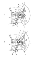
図9および図10は、図5および図6に示すプリンタ1の構成が異なる第1変形例を示す図であり、図9(a)から図10(b)にかけてロール紙Rのロール径が徐々に小さくなる様子を示している。
図9および図10に示すように、本変形例では、デカール部材5は、ダンパ53と、しごき部Sを有するシャフト54を有している。また、ダンパ53は、バネ533を備えている。図9(a)では、ダンパ53とシャフト54を左斜め前方から見た様子を円で囲んで拡大して示している。ダンパ53は、左右方向に長い板状の部材であり、搬送方向下流側(前側)の上端側部分には、その左右方向における、両端部分と中央部分の3箇所にツメ部532が設けられ、これらツメ部532の間にはそれぞれ切欠部531が形成されている。シャフト54は金属製のものであり、本実施形態では、径が約2mmのものを採用している。また、シャフト54における、ツメ部532に対応する箇所には、径を1.7mm程度に絞った縮径部541が形成されている。シャフト54は、その縮径部541がツメ部532にはめ込まれることで、ダンパ53に対して回動自在に取り付けられている。なお、シャフト54は、ダンパ53における左右方向の両端部にEリング等によって固定してもよい。支持部211よりも搬送方向下流側にはダンパ設置部2111が設けられ、ダンパ53は、搬送方向上流側の端部が、紙面と直交する方向に延在した不図示のヒンジ部材によってダンパ設置部2111に取り付けられたものである。これにより、ダンパ53は、ダンパ設置部2111に回動自在に設けられている。また、ダンパ設置部2111よりも搬送方向下流側にバネ収容部2112が設けられ、このバネ収容部2112にバネ533が収容されている。ダンパ53は、バネ533によって一方側(図2参照)に向けて付勢され、これによってしごき部Sを有するシャフト54も一方側(図2参照)に向けて付勢されている。用紙部分Pが搬送方向に搬送されると、用紙部分Pにかかる搬送方向のテンションの強さに応じて、ダンパ53は沈み込む。すなわち、ロール径が大きく、用紙部分Pにかかる搬送方向のテンションが強い場合には、ダンパ53が大きく沈み込む一方、ロール径が小さくなり、用紙部分Pにかかる搬送方向のテンションが弱くなるにつれて、ダンパ53の沈み込む量が減少する。これによって、ロール径の大きさに応じてしごき角αの大きさを調整することができる。さらに、ロール紙Rのロール径が大きい場合や搬送初動時の搬送負荷が軽減され、プラテンローラ31や駆動系部品の劣化損傷、搬送モータにかかる負荷等を軽減することができる。また、シャフト54は、ダンパ53に対して回転自在であるため、シャフト54の摩耗を抑えることができるとともに、用紙部分Pの摩擦負荷を軽減することもできる。
さらに、本変形例では、左側の側壁部212の上端部分には、センサ用の基板2121が設けられ、この基板2121に2つのロール径センサ77,77が設けられている。基板2121は、ロール径センサ77,77が、側壁部212よりも左右方向における外側に位置するように側壁部212に取り付けられている。これにより、ロール径センサ77,77と、ロール紙Rとの干渉が防止される。これらロール径センサ77,77は、透過型センサで構成され、アーム部材6の右側縁部には、ロール径センサ77,77における、投光器と受光器との間を遮蔽可能な遮蔽板63が設けられている。
図9(a)は、ロール紙Rのロール径が最大の場合の様子を示しており、上流側ガイド部材32の上流側押え部F1は、用紙部分Pに接触していない。さらに、用紙部分Pが搬送方向に搬送されると、ロール紙Rの重量によるバックテンションで、用紙部分Pに搬送方向のテンションが強くかかるためダンパ53は大きく沈み込み、しごき角αが大きくなる。この結果、用紙部分Pに付与される矯正力は小さくなる。また、ロール径センサ77は、2つとも遮蔽板63を検出しておらず、用紙部分Pの搬送速度も変化しない。
図9(b)に示すように、ロール紙Rのロール径が小さくなっていくと、アーム部材6が上流側ガイド部材32と係合する。これにより上流側ガイド部材32がアーム部材6に連動し、上流側ガイド部材32の第1押え部F1が用紙部分Pの内面Piに接触する。用紙部分Pが搬送方向に搬送されると、ロール紙Rのロール径が小さくなった分、図9(a)に示す状態に比べて、用紙部分Pにかかる搬送方向のテンションが弱まり、ダンパ53が沈み込む量が減少する。その結果、図9(a)に示す状態に比べて、しごき角αが小さくなり、用紙部分Pに付与される矯正力が強くなる。また、アーム部材6の遮蔽板63は、一方側のロール径センサ77の検知領域を遮蔽した状態になっている。図9(b)では、アーム部材6の遮蔽板63が、一方側のロール径センサ77の検知領域を遮蔽した様子を、左斜め後方から見た斜視図を円で囲んで示している。一方側のロール径センサ77が遮蔽板63によって遮蔽されることにより、一方側のロール径センサ77が検知状態になり、用紙部分Pの搬送速度をやや遅くして、用紙部分Pに付与される矯正力をやや強めている。
図10(a)に示すように、ロール紙Rのロール径がさらに小さくなると、上流側ガイド部材32の第1押え部F1が用紙部分Pの内面Piを一方側(図2参照)から押え、それに加えて、用紙部分Pが搬送される際にダンパ53が沈み込む量もより減少する。その結果、図9(b)に示す状態に比べて、しごき角αが小さくなり、用紙部分Pに付与される矯正力が強くなる。なお、一方側のロール径センサ77のみが検知した状態に変化はないため、用紙部分Pの搬送速度は変わらない。
図10(b)に示すように、ロール紙Rのロール径がまたさらに小さくなると、上流側ガイド部材32の第1押え部F1が用紙部分Pの内面Piを一方側(図2参照)から押える量が増加し、上流側ガイド部材32のストッパ323が下流側ガイド部材33に当接する。また、用紙部分Pが搬送される際にダンパ53が沈み込む量もさらに減少するため、しごき角αがより小さくなり、図10(a)に示す状態に比べて矯正力が強くなる。また、アーム部材6の遮蔽板63は、2つのロール径センサ77,77の検知領域を遮蔽し、両方のロール径センサ77が検知状態になっている。このため、用紙部分Pの搬送速度をさらに遅くし、用紙部分Pに付与される矯正力をさらに強めている。なお、本変形例では、2個のロール径センサ77を用いて用紙部分Pの搬送速度を3通りに変化させているが、1個のロール径センサ77を用いて搬送速度を2通りに変化させてもよいし、3個以上のロール径センサ77を用いて搬送速度を4通り以上に変化させてもよい。
図11は、図9および図10に示すバネ収容部2112の構成が異なる第2変形例を示す図である。
図11(a)に示すように、第2変形例のバネ収容部2112は、壁部2112aと、バネ受け底部2112bを有している。バネ受け底部2112bは、バネ533を受ける部分であり、紙面と直交する方向に延在したヒンジ部材2112cによって壁部2112aの下端部分に回動自在に取り付けられている。図11(b)に示すように、本変形例では、ヒンジ部材2112cを軸にして、バネ受け底部2112bの搬送方向上流側の部分を、図に円弧状の太い矢印で示すように時計回りに回動させることができる。これにより、バネ533の下端部の位置が下方に移動しバネ533が伸びるため、バネ533の付勢力が弱まり、ダンパ53が沈み込みやすくなる。この結果、用紙部分Pにかかる搬送方向のテンションが同じ強さであってもしごき角αが大きくなり、矯正力を弱めることができる。本変形例では、図11(a)に示す状態のしごき角αが90度程度であるのに対し、同図(b)に示す状態のしごき角αが115度程度に大きくなっている。このように、本変形例では、ロール紙Rのロール径の大きさによる矯正力の調整と併せて、バネ533の下端部の位置を下方に移動させることで、用紙の紙厚(厚紙か薄紙か)や紙種、あるいは温度や湿度等の使用環境による巻き癖の度合い等により、矯正力をより細かく調整することができる。なお、バネ受け底部2112bの回動は、手動レバー等を設け手動で行ってもよいし、ソレノイド等によって回動させる態様を採用することもできる。
以上説明したように本実施形態の用紙搬送機構10およびプリンタ1によれば、ロール紙から引き出された用紙部分の巻き癖を、巻き癖の強さに応じて矯正することができる。
本発明は上述の実施の形態に限られることなく特許請求の範囲に記載した範囲で種々の変更を行うことができる。例えば、本実施形態では、ロール紙Rの下側から用紙部分Pを引き出す態様を例に挙げて説明しているが、ロール紙Rの上側から用紙部分Pを引き出し、例えば、下方に向けてしごき部Sを付勢する態様を採用してもよい。また、本実施形態では、上流側押え部F1と下流側押え部F2を備えた態様を例に挙げて説明したが、いずれか一方のみを備える態様としてもよい。また、上流側押え部F1と下流側押え部F2も、しごき部Sと同様に、回転自在なシャフトによって構成してもよい。
なお、以上説明した各実施形態や各変形例の記載それぞれにのみ含まれている構成要件であっても、その構成要件を、他の実施形態や他の変形例に適用してもよい。
10 用紙搬送機構
1 プリンタ
31 プラテンローラ
32 上流側ガイド部材
33 下流側ガイド部材
5 デカール部材
51 ベース部
52 リブ
53 ダンパ
533 バネ
54 シャフト
6 アーム部材
70 プリンタ制御部
77 ロール径センサ
A 収容領域
F1 上流側押え部
F2 下流側押え部
P 用紙部分
Pi 内面
Po 外面
R ロール紙
S しごき部
1 プリンタ
31 プラテンローラ
32 上流側ガイド部材
33 下流側ガイド部材
5 デカール部材
51 ベース部
52 リブ
53 ダンパ
533 バネ
54 シャフト
6 アーム部材
70 プリンタ制御部
77 ロール径センサ
A 収容領域
F1 上流側押え部
F2 下流側押え部
P 用紙部分
Pi 内面
Po 外面
R ロール紙
S しごき部
Claims (5)
- 長尺の用紙の一方側の面を内側にし他方側の面を外側にしてロール状に巻かれたロール紙から用紙部分を搬送する用紙搬送機構において、
通過する前記用紙部分の前記他方側の面に接し、該用紙部分の巻き癖を矯正するしごき部と、
前記用紙部分を前記一方側から押さえ、前記しごき部で該用紙部分を屈曲させる押え部と、
前記ロール紙の外周面に当接し該ロール紙のロール径の変化に追従して動作するアームとを備え、
前記押え部は、前記アームが動作している期間のうちの少なくとも一部の期間で、前記ロール径が小さくなるにつれて前記しごき部で屈曲した状態の用紙部分の内角の大きさも小さくなるように、前記一方側から前記他方側に向かって、該アームに連動して移動するものであることを特徴とする用紙搬送機構。 - 前記押え部は、前記ロール径が上限設定値より大きい期間および該上限設定値より小さい下限設定値未満の期間では停止したものであり、該ロール径が該上限設定値以下であって且つ該下限設定値以上の期間では、該アームに連動して移動するものであることを特徴とする請求項1記載の用紙搬送機構。
- 前記押え部は、前記ロール径が前記上限設定値未満の接触設定値以下であって且つ前記下限設定値以上の期間を前記一部の期間として、前記ロール径が小さくなるにつれて前記内角の大きさも小さくなるように前記一方側から前記他方側に向けて移動するものであることを特徴とする請求項2記載の用紙搬送機構。
- 前記しごき部の、前記用紙部分を基準にして該しごき部とは反対側に設けられた、該用紙部分の一部を収容可能な収容領域と、
前記用紙部分を搬送方向の下流側にバックフィードさせ前記収容領域に該用紙部分をループ化させるバックフィード手段とを備えたことを特徴とする請求項1から3のうちいずれか1項記載の用紙搬送機構。 - 前記用紙部分を搬送する搬送手段と、
前記ロール紙のロール径を検知する検知手段と、
前記搬送手段が前記用紙部分を搬送する搬送速度を前記検知手段で検知した前記ロール径に基づき制御する制御手段とを備え、
前記制御手段は、前記ロール径が所定の大きさよりも小さくなると前記搬送速度を遅くするものであることを特徴とする請求項1から4のうちいずれか1項記載の用紙搬送機構。
Priority Applications (3)
| Application Number | Priority Date | Filing Date | Title |
|---|---|---|---|
| CN201580042963.0A CN106573744B (zh) | 2014-08-12 | 2015-07-22 | 用纸搬送机构 |
| EP15831786.7A EP3196155B1 (en) | 2014-08-12 | 2015-07-22 | Paper transport mechanism |
| US15/404,390 US10457515B2 (en) | 2014-08-12 | 2017-01-12 | Paper conveyance mechanism |
Applications Claiming Priority (2)
| Application Number | Priority Date | Filing Date | Title |
|---|---|---|---|
| JP2014-164604 | 2014-08-12 | ||
| JP2014164604A JP6287680B2 (ja) | 2014-08-12 | 2014-08-12 | 用紙搬送機構 |
Related Child Applications (1)
| Application Number | Title | Priority Date | Filing Date |
|---|---|---|---|
| US15/404,390 Continuation US10457515B2 (en) | 2014-08-12 | 2017-01-12 | Paper conveyance mechanism |
Publications (1)
| Publication Number | Publication Date |
|---|---|
| WO2016024466A1 true WO2016024466A1 (ja) | 2016-02-18 |
Family
ID=55304095
Family Applications (1)
| Application Number | Title | Priority Date | Filing Date |
|---|---|---|---|
| PCT/JP2015/070823 Ceased WO2016024466A1 (ja) | 2014-08-12 | 2015-07-22 | 用紙搬送機構 |
Country Status (5)
| Country | Link |
|---|---|
| US (1) | US10457515B2 (ja) |
| EP (1) | EP3196155B1 (ja) |
| JP (1) | JP6287680B2 (ja) |
| CN (1) | CN106573744B (ja) |
| WO (1) | WO2016024466A1 (ja) |
Families Citing this family (18)
| Publication number | Priority date | Publication date | Assignee | Title |
|---|---|---|---|---|
| US11020870B2 (en) * | 2018-10-31 | 2021-06-01 | Automatic Handling International, Inc. | Apparatus for slabbing rolls of tissue |
| JP2020100473A (ja) * | 2018-12-21 | 2020-07-02 | 東芝テック株式会社 | プリンタ |
| KR102026311B1 (ko) * | 2019-02-27 | 2019-09-27 | 망고슬래브 주식회사 | 프린터 |
| JP7298867B2 (ja) * | 2019-03-08 | 2023-06-27 | 株式会社タカゾノ | 巻回体と包装装置との組み合わせ |
| JP7634932B2 (ja) * | 2019-08-30 | 2025-02-25 | セイコーエプソン株式会社 | 印刷装置 |
| JP7746014B2 (ja) * | 2021-02-02 | 2025-09-30 | 東芝テック株式会社 | 用紙収納装置 |
| JP7645100B2 (ja) * | 2021-03-05 | 2025-03-13 | 東芝テック株式会社 | プリンタ装置 |
| JP2022135695A (ja) * | 2021-03-05 | 2022-09-15 | 東芝テック株式会社 | プリンタ装置 |
| JP6975868B1 (ja) * | 2021-03-17 | 2021-12-01 | シチズン時計株式会社 | プリンタ |
| JP7830905B2 (ja) * | 2021-11-29 | 2026-03-17 | セイコーエプソン株式会社 | 印刷装置 |
| JP7764744B2 (ja) * | 2021-12-01 | 2025-11-06 | セイコーエプソン株式会社 | ロール紙プリンター |
| JP7746870B2 (ja) * | 2022-02-03 | 2025-10-01 | セイコーエプソン株式会社 | ロール紙プリンター |
| JP7784346B2 (ja) | 2022-04-25 | 2025-12-11 | 東芝テック株式会社 | プリンタ装置 |
| JP2024064461A (ja) * | 2022-10-28 | 2024-05-14 | セイコーエプソン株式会社 | ロール紙プリンター |
| CN115922841A (zh) * | 2023-01-12 | 2023-04-07 | 安徽庞度环保科技有限公司 | 一种反弯自动调节的纸卷冲切机及冲切方法 |
| CN116675043B (zh) * | 2023-07-07 | 2025-12-09 | 维达纸业(中国)有限公司 | 一种用于自动进浆板的传送装置 |
| JP2025145178A (ja) * | 2024-03-21 | 2025-10-03 | 東芝テック株式会社 | プリンタ |
| CN118457068B (zh) * | 2024-07-11 | 2024-12-20 | 珠海恒茂电子科技有限公司 | 一种反向折弯通道的走纸机构 |
Citations (4)
| Publication number | Priority date | Publication date | Assignee | Title |
|---|---|---|---|---|
| JPS6056650U (ja) * | 1983-09-26 | 1985-04-20 | 株式会社東芝 | ロ−ル状記録紙のカ−ル除去装置 |
| JPH0378365U (ja) * | 1989-07-31 | 1991-08-08 | ||
| JPH0568999U (ja) * | 1992-02-26 | 1993-09-17 | 株式会社リコー | 記録紙搬送装置 |
| JP2006225139A (ja) * | 2005-02-21 | 2006-08-31 | Seiko Instruments Inc | カール除去機構および、これを備えたプリンタ |
Family Cites Families (28)
| Publication number | Priority date | Publication date | Assignee | Title |
|---|---|---|---|---|
| US1654946A (en) * | 1927-05-12 | 1928-01-03 | Charles M Sinks | Automatic paper-straightening attachment for adding machines |
| US1807274A (en) * | 1927-08-09 | 1931-05-26 | George C Beidler | Film straightening device |
| US3604652A (en) * | 1969-07-02 | 1971-09-14 | Addressograph Multigraph | Roll sheeter for printing machine |
| GB1360191A (en) * | 1971-07-22 | 1974-07-17 | Molins Ltd | Web feeding |
| JPS5241869Y2 (ja) * | 1972-12-27 | 1977-09-22 | ||
| JPS49106346A (ja) | 1973-02-09 | 1974-10-08 | ||
| JPS58188254A (ja) * | 1982-04-23 | 1983-11-02 | Fuji Xerox Co Ltd | ロ−ル紙のカ−ル矯正装置 |
| JPS6056650A (ja) | 1983-09-07 | 1985-04-02 | Aoki Seisakusho:Kk | ル−フキヤリヤ− |
| JPS6164655A (ja) * | 1984-09-05 | 1986-04-03 | Hitachi Ltd | ロ−ル紙矯正機構 |
| JPH0688710B2 (ja) * | 1988-05-10 | 1994-11-09 | 株式会社小林製作所 | シートカール矯正装置 |
| EP0372478B1 (en) * | 1988-12-05 | 1997-10-22 | Canon Kabushiki Kaisha | Curl correction apparatus |
| JPH0356349A (ja) * | 1989-07-24 | 1991-03-11 | Canon Inc | 記録装置 |
| JPH0378365A (ja) | 1989-08-21 | 1991-04-03 | Parusutetsuku Kogyo Kk | 情報提供装置 |
| US5009749A (en) * | 1990-08-09 | 1991-04-23 | Martin Automatic, Inc. | Web decurler |
| JPH04351159A (ja) * | 1991-05-29 | 1992-12-04 | Canon Inc | 記録装置 |
| JP2910345B2 (ja) * | 1991-08-29 | 1999-06-23 | 富士通株式会社 | ロール紙のカール取り装置 |
| JPH0568999A (ja) | 1991-09-10 | 1993-03-23 | Dam Suigenchi Kankyo Seibi Center | プランクトンの増殖抑制方法およびその装置 |
| JPH05208765A (ja) * | 1992-01-31 | 1993-08-20 | Yupiteru Kogyo Kk | ロール記録紙の逆反り防止方法及び防止装置 |
| JP3249200B2 (ja) * | 1992-09-16 | 2002-01-21 | 株式会社リコー | カール矯正装置 |
| US5717836A (en) * | 1995-03-09 | 1998-02-10 | Matsushita Electric Industrial Co., Ltd. | Printing apparatus having a retractable curl removal member and reversible roller |
| EP1391408A1 (en) * | 2001-03-26 | 2004-02-25 | F & F Limited | Paper feeder and printer |
| US6908242B2 (en) * | 2001-12-04 | 2005-06-21 | Seiko Epson Corporation | Roll paper curl correction device and record apparatus with the roll paper curl correction device |
| JP4079709B2 (ja) | 2002-07-22 | 2008-04-23 | 横浜ゴム株式会社 | タイヤホイール組立体及びランフラット用支持体 |
| US7618204B2 (en) * | 2006-04-24 | 2009-11-17 | Avery Dennison Retail Information Services Llc | Decurling tag webs in printers/stackers |
| WO2006038624A1 (ja) * | 2004-10-06 | 2006-04-13 | Citizen Watch Co., Ltd. | プリンター |
| JP2007197123A (ja) * | 2006-01-24 | 2007-08-09 | Sony Corp | 記録紙カール矯正機構、画像形成装置、及び記録紙カール矯正方法 |
| JP4985434B2 (ja) * | 2008-01-29 | 2012-07-25 | Nkワークス株式会社 | デカール機構 |
| JP5467861B2 (ja) * | 2009-12-28 | 2014-04-09 | スター精密株式会社 | カッター機構付き印刷装置 |
-
2014
- 2014-08-12 JP JP2014164604A patent/JP6287680B2/ja active Active
-
2015
- 2015-07-22 EP EP15831786.7A patent/EP3196155B1/en active Active
- 2015-07-22 CN CN201580042963.0A patent/CN106573744B/zh active Active
- 2015-07-22 WO PCT/JP2015/070823 patent/WO2016024466A1/ja not_active Ceased
-
2017
- 2017-01-12 US US15/404,390 patent/US10457515B2/en active Active
Patent Citations (4)
| Publication number | Priority date | Publication date | Assignee | Title |
|---|---|---|---|---|
| JPS6056650U (ja) * | 1983-09-26 | 1985-04-20 | 株式会社東芝 | ロ−ル状記録紙のカ−ル除去装置 |
| JPH0378365U (ja) * | 1989-07-31 | 1991-08-08 | ||
| JPH0568999U (ja) * | 1992-02-26 | 1993-09-17 | 株式会社リコー | 記録紙搬送装置 |
| JP2006225139A (ja) * | 2005-02-21 | 2006-08-31 | Seiko Instruments Inc | カール除去機構および、これを備えたプリンタ |
Also Published As
| Publication number | Publication date |
|---|---|
| JP6287680B2 (ja) | 2018-03-07 |
| EP3196155B1 (en) | 2020-05-06 |
| JP2016040194A (ja) | 2016-03-24 |
| US20170121142A1 (en) | 2017-05-04 |
| EP3196155A4 (en) | 2018-03-28 |
| EP3196155A1 (en) | 2017-07-26 |
| CN106573744A (zh) | 2017-04-19 |
| US10457515B2 (en) | 2019-10-29 |
| CN106573744B (zh) | 2018-09-28 |
Similar Documents
| Publication | Publication Date | Title |
|---|---|---|
| JP6287680B2 (ja) | 用紙搬送機構 | |
| WO2016013576A1 (ja) | 用紙搬送機構 | |
| JP6202648B1 (ja) | ロール紙プリンタ | |
| JP4409344B2 (ja) | プリンタ | |
| JP7000064B2 (ja) | シート搬送装置及び画像形成装置 | |
| JP2017132576A (ja) | 用紙搬送機構 | |
| JP6334791B2 (ja) | ロール紙プリンタ | |
| JP6414521B2 (ja) | 印刷装置 | |
| JP2018111610A (ja) | ロール紙プリンタ | |
| JP2019182556A (ja) | 給紙装置、およびそれを備えた画像形成装置 | |
| JP4315081B2 (ja) | スイッチバック装置及びこれを備えた画像形成装置 | |
| CN106348064B (zh) | 卷曲矫正装置和图像形成装置 | |
| JP2012171703A (ja) | デカール装置 | |
| JP6719274B2 (ja) | カール矯正装置及び画像形成装置 | |
| JP3770313B2 (ja) | ロール紙の巻き癖矯正装置及び該ロール紙の巻き癖矯正装置を備える記録装置 | |
| JP2018070305A (ja) | 排出装置及び画像形成装置 | |
| JP2010082846A (ja) | 画像記録装置 | |
| JP2020019582A (ja) | 粘着剤転写機構及びプリンタ | |
| JP7056432B2 (ja) | 媒体搬送装置および画像形成装置 | |
| WO2025164165A1 (ja) | 記録装置 | |
| JP2020019159A (ja) | 粘着剤転写機構を備えるプリンタの制御方法及びプログラム | |
| JP3738833B2 (ja) | ロール紙の巻き癖矯正装置及び該ロール紙の巻き癖矯正装置を備える記録装置 | |
| JP3852575B2 (ja) | 搬送媒体送り装置および該搬送媒体送り装置を備えた記録装置 | |
| JP3755590B2 (ja) | 記録装置 | |
| WO2025164164A1 (ja) | 記録装置 |
Legal Events
| Date | Code | Title | Description |
|---|---|---|---|
| 121 | Ep: the epo has been informed by wipo that ep was designated in this application |
Ref document number: 15831786 Country of ref document: EP Kind code of ref document: A1 |
|
| REEP | Request for entry into the european phase |
Ref document number: 2015831786 Country of ref document: EP |
|
| WWE | Wipo information: entry into national phase |
Ref document number: 2015831786 Country of ref document: EP |
|
| NENP | Non-entry into the national phase |
Ref country code: DE |