WO2016035694A1 - エネルギー吸収部材 - Google Patents
エネルギー吸収部材 Download PDFInfo
- Publication number
- WO2016035694A1 WO2016035694A1 PCT/JP2015/074370 JP2015074370W WO2016035694A1 WO 2016035694 A1 WO2016035694 A1 WO 2016035694A1 JP 2015074370 W JP2015074370 W JP 2015074370W WO 2016035694 A1 WO2016035694 A1 WO 2016035694A1
- Authority
- WO
- WIPO (PCT)
- Prior art keywords
- fiber
- load
- shape holding
- trigger
- fiber layer
- Prior art date
- Legal status (The legal status is an assumption and is not a legal conclusion. Google has not performed a legal analysis and makes no representation as to the accuracy of the status listed.)
- Ceased
Links
Images

Classifications
-
- D—TEXTILES; PAPER
- D03—WEAVING
- D03D—WOVEN FABRICS; METHODS OF WEAVING; LOOMS
- D03D3/00—Woven fabrics characterised by their shape
- D03D3/02—Tubular fabrics
-
- B—PERFORMING OPERATIONS; TRANSPORTING
- B60—VEHICLES IN GENERAL
- B60R—VEHICLES, VEHICLE FITTINGS, OR VEHICLE PARTS, NOT OTHERWISE PROVIDED FOR
- B60R19/00—Wheel guards; Radiator guards, e.g. grilles; Obstruction removers; Fittings damping bouncing force in collisions
- B60R19/02—Bumpers, i.e. impact receiving or absorbing members for protecting vehicles or fending off blows from other vehicles or objects
- B60R19/24—Arrangements for mounting bumpers on vehicles
- B60R19/26—Arrangements for mounting bumpers on vehicles comprising yieldable mounting means
- B60R19/30—Elastomeric material
-
- B—PERFORMING OPERATIONS; TRANSPORTING
- B32—LAYERED PRODUCTS
- B32B—LAYERED PRODUCTS, i.e. PRODUCTS BUILT-UP OF STRATA OF FLAT OR NON-FLAT, e.g. CELLULAR OR HONEYCOMB, FORM
- B32B1/00—Layered products having a non-planar shape
- B32B1/08—Tubular products
-
- B—PERFORMING OPERATIONS; TRANSPORTING
- B32—LAYERED PRODUCTS
- B32B—LAYERED PRODUCTS, i.e. PRODUCTS BUILT-UP OF STRATA OF FLAT OR NON-FLAT, e.g. CELLULAR OR HONEYCOMB, FORM
- B32B3/00—Layered products comprising a layer with external or internal discontinuities or unevennesses, or a layer of non-planar shape; Layered products comprising a layer having particular features of form
- B32B3/02—Layered products comprising a layer with external or internal discontinuities or unevennesses, or a layer of non-planar shape; Layered products comprising a layer having particular features of form characterised by features of form at particular places, e.g. in edge regions
- B32B3/08—Layered products comprising a layer with external or internal discontinuities or unevennesses, or a layer of non-planar shape; Layered products comprising a layer having particular features of form characterised by features of form at particular places, e.g. in edge regions characterised by added members at particular parts
- B32B3/085—Layered products comprising a layer with external or internal discontinuities or unevennesses, or a layer of non-planar shape; Layered products comprising a layer having particular features of form characterised by features of form at particular places, e.g. in edge regions characterised by added members at particular parts spaced apart pieces on the surface of a layer
-
- B—PERFORMING OPERATIONS; TRANSPORTING
- B32—LAYERED PRODUCTS
- B32B—LAYERED PRODUCTS, i.e. PRODUCTS BUILT-UP OF STRATA OF FLAT OR NON-FLAT, e.g. CELLULAR OR HONEYCOMB, FORM
- B32B5/00—Layered products characterised by the non- homogeneity or physical structure, i.e. comprising a fibrous, filamentary, particulate or foam layer; Layered products characterised by having a layer differing constitutionally or physically in different parts
- B32B5/02—Layered products characterised by the non- homogeneity or physical structure, i.e. comprising a fibrous, filamentary, particulate or foam layer; Layered products characterised by having a layer differing constitutionally or physically in different parts characterised by structural features of a fibrous or filamentary layer
- B32B5/024—Woven fabric
-
- B—PERFORMING OPERATIONS; TRANSPORTING
- B32—LAYERED PRODUCTS
- B32B—LAYERED PRODUCTS, i.e. PRODUCTS BUILT-UP OF STRATA OF FLAT OR NON-FLAT, e.g. CELLULAR OR HONEYCOMB, FORM
- B32B5/00—Layered products characterised by the non- homogeneity or physical structure, i.e. comprising a fibrous, filamentary, particulate or foam layer; Layered products characterised by having a layer differing constitutionally or physically in different parts
- B32B5/02—Layered products characterised by the non- homogeneity or physical structure, i.e. comprising a fibrous, filamentary, particulate or foam layer; Layered products characterised by having a layer differing constitutionally or physically in different parts characterised by structural features of a fibrous or filamentary layer
- B32B5/06—Layered products characterised by the non- homogeneity or physical structure, i.e. comprising a fibrous, filamentary, particulate or foam layer; Layered products characterised by having a layer differing constitutionally or physically in different parts characterised by structural features of a fibrous or filamentary layer characterised by a fibrous or filamentary layer mechanically connected, e.g. by needling to another layer, e.g. of fibres, of paper
-
- B—PERFORMING OPERATIONS; TRANSPORTING
- B32—LAYERED PRODUCTS
- B32B—LAYERED PRODUCTS, i.e. PRODUCTS BUILT-UP OF STRATA OF FLAT OR NON-FLAT, e.g. CELLULAR OR HONEYCOMB, FORM
- B32B5/00—Layered products characterised by the non- homogeneity or physical structure, i.e. comprising a fibrous, filamentary, particulate or foam layer; Layered products characterised by having a layer differing constitutionally or physically in different parts
- B32B5/14—Layered products characterised by the non- homogeneity or physical structure, i.e. comprising a fibrous, filamentary, particulate or foam layer; Layered products characterised by having a layer differing constitutionally or physically in different parts characterised by a layer differing constitutionally or physically in different parts, e.g. denser near its faces
- B32B5/142—Variation across the area of the layer
-
- B—PERFORMING OPERATIONS; TRANSPORTING
- B32—LAYERED PRODUCTS
- B32B—LAYERED PRODUCTS, i.e. PRODUCTS BUILT-UP OF STRATA OF FLAT OR NON-FLAT, e.g. CELLULAR OR HONEYCOMB, FORM
- B32B5/00—Layered products characterised by the non- homogeneity or physical structure, i.e. comprising a fibrous, filamentary, particulate or foam layer; Layered products characterised by having a layer differing constitutionally or physically in different parts
- B32B5/14—Layered products characterised by the non- homogeneity or physical structure, i.e. comprising a fibrous, filamentary, particulate or foam layer; Layered products characterised by having a layer differing constitutionally or physically in different parts characterised by a layer differing constitutionally or physically in different parts, e.g. denser near its faces
- B32B5/145—Variation across the thickness of the layer
-
- B—PERFORMING OPERATIONS; TRANSPORTING
- B32—LAYERED PRODUCTS
- B32B—LAYERED PRODUCTS, i.e. PRODUCTS BUILT-UP OF STRATA OF FLAT OR NON-FLAT, e.g. CELLULAR OR HONEYCOMB, FORM
- B32B5/00—Layered products characterised by the non- homogeneity or physical structure, i.e. comprising a fibrous, filamentary, particulate or foam layer; Layered products characterised by having a layer differing constitutionally or physically in different parts
- B32B5/22—Layered products characterised by the non- homogeneity or physical structure, i.e. comprising a fibrous, filamentary, particulate or foam layer; Layered products characterised by having a layer differing constitutionally or physically in different parts characterised by the presence of two or more layers which are next to each other and are fibrous, filamentary, formed of particles or foamed
- B32B5/24—Layered products characterised by the non- homogeneity or physical structure, i.e. comprising a fibrous, filamentary, particulate or foam layer; Layered products characterised by having a layer differing constitutionally or physically in different parts characterised by the presence of two or more layers which are next to each other and are fibrous, filamentary, formed of particles or foamed one layer being a fibrous or filamentary layer
- B32B5/26—Layered products characterised by the non- homogeneity or physical structure, i.e. comprising a fibrous, filamentary, particulate or foam layer; Layered products characterised by having a layer differing constitutionally or physically in different parts characterised by the presence of two or more layers which are next to each other and are fibrous, filamentary, formed of particles or foamed one layer being a fibrous or filamentary layer another layer next to it also being fibrous or filamentary
-
- B—PERFORMING OPERATIONS; TRANSPORTING
- B32—LAYERED PRODUCTS
- B32B—LAYERED PRODUCTS, i.e. PRODUCTS BUILT-UP OF STRATA OF FLAT OR NON-FLAT, e.g. CELLULAR OR HONEYCOMB, FORM
- B32B5/00—Layered products characterised by the non- homogeneity or physical structure, i.e. comprising a fibrous, filamentary, particulate or foam layer; Layered products characterised by having a layer differing constitutionally or physically in different parts
- B32B5/22—Layered products characterised by the non- homogeneity or physical structure, i.e. comprising a fibrous, filamentary, particulate or foam layer; Layered products characterised by having a layer differing constitutionally or physically in different parts characterised by the presence of two or more layers which are next to each other and are fibrous, filamentary, formed of particles or foamed
- B32B5/24—Layered products characterised by the non- homogeneity or physical structure, i.e. comprising a fibrous, filamentary, particulate or foam layer; Layered products characterised by having a layer differing constitutionally or physically in different parts characterised by the presence of two or more layers which are next to each other and are fibrous, filamentary, formed of particles or foamed one layer being a fibrous or filamentary layer
- B32B5/28—Layered products characterised by the non- homogeneity or physical structure, i.e. comprising a fibrous, filamentary, particulate or foam layer; Layered products characterised by having a layer differing constitutionally or physically in different parts characterised by the presence of two or more layers which are next to each other and are fibrous, filamentary, formed of particles or foamed one layer being a fibrous or filamentary layer impregnated with or embedded in a plastic substance
-
- B—PERFORMING OPERATIONS; TRANSPORTING
- B60—VEHICLES IN GENERAL
- B60R—VEHICLES, VEHICLE FITTINGS, OR VEHICLE PARTS, NOT OTHERWISE PROVIDED FOR
- B60R19/00—Wheel guards; Radiator guards, e.g. grilles; Obstruction removers; Fittings damping bouncing force in collisions
- B60R19/02—Bumpers, i.e. impact receiving or absorbing members for protecting vehicles or fending off blows from other vehicles or objects
- B60R19/24—Arrangements for mounting bumpers on vehicles
- B60R19/26—Arrangements for mounting bumpers on vehicles comprising yieldable mounting means
- B60R19/34—Arrangements for mounting bumpers on vehicles comprising yieldable mounting means destroyed upon impact, e.g. one-shot type
-
- D—TEXTILES; PAPER
- D03—WEAVING
- D03D—WOVEN FABRICS; METHODS OF WEAVING; LOOMS
- D03D1/00—Woven fabrics designed to make specified articles
-
- D—TEXTILES; PAPER
- D03—WEAVING
- D03D—WOVEN FABRICS; METHODS OF WEAVING; LOOMS
- D03D11/00—Double or multi-ply fabrics not otherwise provided for
-
- D—TEXTILES; PAPER
- D04—BRAIDING; LACE-MAKING; KNITTING; TRIMMINGS; NON-WOVEN FABRICS
- D04C—BRAIDING OR MANUFACTURE OF LACE, INCLUDING BOBBIN-NET OR CARBONISED LACE; BRAIDING MACHINES; BRAID; LACE
- D04C1/00—Braid or lace, e.g. pillow-lace; Processes for the manufacture thereof
- D04C1/06—Braid or lace serving particular purposes
-
- F—MECHANICAL ENGINEERING; LIGHTING; HEATING; WEAPONS; BLASTING
- F16—ENGINEERING ELEMENTS AND UNITS; GENERAL MEASURES FOR PRODUCING AND MAINTAINING EFFECTIVE FUNCTIONING OF MACHINES OR INSTALLATIONS; THERMAL INSULATION IN GENERAL
- F16F—SPRINGS; SHOCK-ABSORBERS; MEANS FOR DAMPING VIBRATION
- F16F1/00—Springs
- F16F1/36—Springs made of rubber or other material having high internal friction, e.g. thermoplastic elastomers
- F16F1/366—Springs made of rubber or other material having high internal friction, e.g. thermoplastic elastomers made of fibre-reinforced plastics, i.e. characterised by their special construction from such materials
-
- F—MECHANICAL ENGINEERING; LIGHTING; HEATING; WEAPONS; BLASTING
- F16—ENGINEERING ELEMENTS AND UNITS; GENERAL MEASURES FOR PRODUCING AND MAINTAINING EFFECTIVE FUNCTIONING OF MACHINES OR INSTALLATIONS; THERMAL INSULATION IN GENERAL
- F16F—SPRINGS; SHOCK-ABSORBERS; MEANS FOR DAMPING VIBRATION
- F16F7/00—Vibration-dampers; Shock-absorbers
- F16F7/12—Vibration-dampers; Shock-absorbers using plastic deformation of members
- F16F7/124—Vibration-dampers; Shock-absorbers using plastic deformation of members characterised by their special construction from fibre-reinforced plastics
-
- B—PERFORMING OPERATIONS; TRANSPORTING
- B32—LAYERED PRODUCTS
- B32B—LAYERED PRODUCTS, i.e. PRODUCTS BUILT-UP OF STRATA OF FLAT OR NON-FLAT, e.g. CELLULAR OR HONEYCOMB, FORM
- B32B2250/00—Layers arrangement
- B32B2250/03—3 layers
-
- B—PERFORMING OPERATIONS; TRANSPORTING
- B32—LAYERED PRODUCTS
- B32B—LAYERED PRODUCTS, i.e. PRODUCTS BUILT-UP OF STRATA OF FLAT OR NON-FLAT, e.g. CELLULAR OR HONEYCOMB, FORM
- B32B2250/00—Layers arrangement
- B32B2250/04—4 layers
-
- B—PERFORMING OPERATIONS; TRANSPORTING
- B32—LAYERED PRODUCTS
- B32B—LAYERED PRODUCTS, i.e. PRODUCTS BUILT-UP OF STRATA OF FLAT OR NON-FLAT, e.g. CELLULAR OR HONEYCOMB, FORM
- B32B2250/00—Layers arrangement
- B32B2250/05—5 or more layers
-
- B—PERFORMING OPERATIONS; TRANSPORTING
- B32—LAYERED PRODUCTS
- B32B—LAYERED PRODUCTS, i.e. PRODUCTS BUILT-UP OF STRATA OF FLAT OR NON-FLAT, e.g. CELLULAR OR HONEYCOMB, FORM
- B32B2260/00—Layered product comprising an impregnated, embedded, or bonded layer wherein the layer comprises an impregnation, embedding, or binder material
- B32B2260/02—Composition of the impregnated, bonded or embedded layer
- B32B2260/021—Fibrous or filamentary layer
- B32B2260/023—Two or more layers
-
- B—PERFORMING OPERATIONS; TRANSPORTING
- B32—LAYERED PRODUCTS
- B32B—LAYERED PRODUCTS, i.e. PRODUCTS BUILT-UP OF STRATA OF FLAT OR NON-FLAT, e.g. CELLULAR OR HONEYCOMB, FORM
- B32B2260/00—Layered product comprising an impregnated, embedded, or bonded layer wherein the layer comprises an impregnation, embedding, or binder material
- B32B2260/04—Impregnation, embedding, or binder material
- B32B2260/046—Synthetic resin
-
- B—PERFORMING OPERATIONS; TRANSPORTING
- B32—LAYERED PRODUCTS
- B32B—LAYERED PRODUCTS, i.e. PRODUCTS BUILT-UP OF STRATA OF FLAT OR NON-FLAT, e.g. CELLULAR OR HONEYCOMB, FORM
- B32B2262/00—Composition or structural features of fibres which form a fibrous or filamentary layer or are present as additives
- B32B2262/02—Synthetic macromolecular fibres
- B32B2262/0253—Polyolefin fibres
-
- B—PERFORMING OPERATIONS; TRANSPORTING
- B32—LAYERED PRODUCTS
- B32B—LAYERED PRODUCTS, i.e. PRODUCTS BUILT-UP OF STRATA OF FLAT OR NON-FLAT, e.g. CELLULAR OR HONEYCOMB, FORM
- B32B2262/00—Composition or structural features of fibres which form a fibrous or filamentary layer or are present as additives
- B32B2262/02—Synthetic macromolecular fibres
- B32B2262/0261—Polyamide fibres
- B32B2262/0269—Aromatic polyamide fibres
-
- B—PERFORMING OPERATIONS; TRANSPORTING
- B32—LAYERED PRODUCTS
- B32B—LAYERED PRODUCTS, i.e. PRODUCTS BUILT-UP OF STRATA OF FLAT OR NON-FLAT, e.g. CELLULAR OR HONEYCOMB, FORM
- B32B2262/00—Composition or structural features of fibres which form a fibrous or filamentary layer or are present as additives
- B32B2262/10—Inorganic fibres
- B32B2262/101—Glass fibres
-
- B—PERFORMING OPERATIONS; TRANSPORTING
- B32—LAYERED PRODUCTS
- B32B—LAYERED PRODUCTS, i.e. PRODUCTS BUILT-UP OF STRATA OF FLAT OR NON-FLAT, e.g. CELLULAR OR HONEYCOMB, FORM
- B32B2262/00—Composition or structural features of fibres which form a fibrous or filamentary layer or are present as additives
- B32B2262/10—Inorganic fibres
- B32B2262/105—Ceramic fibres
-
- B—PERFORMING OPERATIONS; TRANSPORTING
- B32—LAYERED PRODUCTS
- B32B—LAYERED PRODUCTS, i.e. PRODUCTS BUILT-UP OF STRATA OF FLAT OR NON-FLAT, e.g. CELLULAR OR HONEYCOMB, FORM
- B32B2262/00—Composition or structural features of fibres which form a fibrous or filamentary layer or are present as additives
- B32B2262/10—Inorganic fibres
- B32B2262/106—Carbon fibres, e.g. graphite fibres
-
- B—PERFORMING OPERATIONS; TRANSPORTING
- B32—LAYERED PRODUCTS
- B32B—LAYERED PRODUCTS, i.e. PRODUCTS BUILT-UP OF STRATA OF FLAT OR NON-FLAT, e.g. CELLULAR OR HONEYCOMB, FORM
- B32B2307/00—Properties of the layers or laminate
- B32B2307/50—Properties of the layers or laminate having particular mechanical properties
- B32B2307/56—Damping, energy absorption
-
- B—PERFORMING OPERATIONS; TRANSPORTING
- B32—LAYERED PRODUCTS
- B32B—LAYERED PRODUCTS, i.e. PRODUCTS BUILT-UP OF STRATA OF FLAT OR NON-FLAT, e.g. CELLULAR OR HONEYCOMB, FORM
- B32B2605/00—Vehicles
- B32B2605/08—Cars
-
- B—PERFORMING OPERATIONS; TRANSPORTING
- B60—VEHICLES IN GENERAL
- B60R—VEHICLES, VEHICLE FITTINGS, OR VEHICLE PARTS, NOT OTHERWISE PROVIDED FOR
- B60R19/00—Wheel guards; Radiator guards, e.g. grilles; Obstruction removers; Fittings damping bouncing force in collisions
- B60R19/02—Bumpers, i.e. impact receiving or absorbing members for protecting vehicles or fending off blows from other vehicles or objects
- B60R19/03—Bumpers, i.e. impact receiving or absorbing members for protecting vehicles or fending off blows from other vehicles or objects characterised by material, e.g. composite
-
- B—PERFORMING OPERATIONS; TRANSPORTING
- B60—VEHICLES IN GENERAL
- B60R—VEHICLES, VEHICLE FITTINGS, OR VEHICLE PARTS, NOT OTHERWISE PROVIDED FOR
- B60R19/00—Wheel guards; Radiator guards, e.g. grilles; Obstruction removers; Fittings damping bouncing force in collisions
- B60R19/02—Bumpers, i.e. impact receiving or absorbing members for protecting vehicles or fending off blows from other vehicles or objects
- B60R19/24—Arrangements for mounting bumpers on vehicles
- B60R19/26—Arrangements for mounting bumpers on vehicles comprising yieldable mounting means
-
- D—TEXTILES; PAPER
- D10—INDEXING SCHEME ASSOCIATED WITH SUBLASSES OF SECTION D, RELATING TO TEXTILES
- D10B—INDEXING SCHEME ASSOCIATED WITH SUBLASSES OF SECTION D, RELATING TO TEXTILES
- D10B2505/00—Industrial
- D10B2505/02—Reinforcing materials; Prepregs
-
- F—MECHANICAL ENGINEERING; LIGHTING; HEATING; WEAPONS; BLASTING
- F16—ENGINEERING ELEMENTS AND UNITS; GENERAL MEASURES FOR PRODUCING AND MAINTAINING EFFECTIVE FUNCTIONING OF MACHINES OR INSTALLATIONS; THERMAL INSULATION IN GENERAL
- F16F—SPRINGS; SHOCK-ABSORBERS; MEANS FOR DAMPING VIBRATION
- F16F7/00—Vibration-dampers; Shock-absorbers
- F16F7/12—Vibration-dampers; Shock-absorbers using plastic deformation of members
Definitions
- the present invention relates to an energy absorbing member that includes a fiber structure having an impregnated resin and absorbs impact energy when subjected to an impact load.
- an energy absorbing member is disposed between the bumper and the body frame.
- This energy absorbing member absorbs impact energy due to its own destruction when receiving an excessive impact load.
- a fiber reinforced composite material having an excellent energy absorbing ability is known.
- the energy absorbing member has a trigger portion that becomes a starting point of destruction when receiving an excessive impact load.
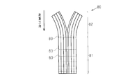
- the shock absorbing composite material structure 80 disclosed in Patent Document 1 includes a fiber laminate having an impregnated resin.
- the fiber laminate has a plurality of laminated reinforcing fibers.
- the shock absorbing composite structure 80 has a trigger portion 82 in a range from a tip in a direction in which a load is applied (hereinafter referred to as a load direction) to a predetermined position along the load direction.
- the trigger part 82 is provided so as not to improve the interlayer bonding force of the fiber laminate.
- the portion beyond the predetermined position, that is, the portion excluding the trigger portion 82 is an interlayer reinforcement region 81 in which the interlayer coupling force is improved by the need ring 83.
- the trigger portion 82 when an excessive impact load is applied, the trigger portion 82 is locally destroyed prior to the interlayer reinforcement region 81 to absorb energy, and the progress of the fracture in the interlayer reinforcement region 81 is achieved. Suppress.
- the trigger portion 82 in the state of the fiber laminate before impregnating the resin, the trigger portion 82 is easily torn or bent in the load direction from the tip. For this reason, in order to impregnate the fiber laminate, for example, during the operation of enclosing the fiber laminate in a mold, as shown in FIG. Will bend. Therefore, handling of the fiber laminate is very bad, and the productivity of the impact-absorbing composite structure 80 may be reduced.
- An object of the present invention is to provide an energy absorbing member that can suppress a decrease in productivity.
- an energy absorbing member configured to absorb impact energy when subjected to an impact load.
- the energy absorbing member includes a fiber structure having an impregnated resin.
- the said fiber structure has a some fiber layer laminated
- Each fiber layer is formed by arranging a plurality of load direction yarns extending in a direction in which a load is applied.
- the fiber structure has an interlayer bonding force due to the bonding of the plurality of fiber layers.
- the fiber structure has a first end surface configured to be loaded first, and a second end surface located on the opposite side of the first end surface in the direction in which the load is applied.
- the fiber structure includes a shape holding portion including the first end surface, a main body portion including the second end surface, and suppressing progress of destruction of the fiber structure, and between the shape holding portion and the main body portion. And a trigger portion that becomes a starting point of destruction when receiving an impact load.
- Each of the shape holding part and the main body part has a higher interlayer bonding force than the trigger part due to the woven structure.
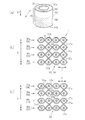
- (A) is a perspective view which shows the energy absorption member of 1st Embodiment
- (b) is a plane sectional view which shows a shape holding
- (c) is a plane sectional view which shows a trigger part.
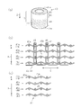
- (A) is a perspective view which shows the energy absorption member of 2nd Embodiment
- (b) is a plane sectional view which shows a shape holding
- (c) is a plane sectional view which shows a trigger part.
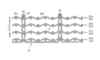
- (A) is a perspective view which shows the energy absorption member of 3rd Embodiment
- (b) is a plane sectional view which shows a shape holding
- (c) is a plane sectional view which shows a trigger part.
- the plane sectional view showing another example of the trigger part in a 3rd embodiment.
- the energy absorption member 10 is a fiber reinforced composite material.
- the energy absorbing member 10 is configured by impregnating a cylindrical fiber structure 11 with a thermosetting resin 15 as a matrix resin. That is, the energy absorbing member 10 includes a fiber structure 11 having an impregnated thermosetting resin 15.
- the energy absorbing member 10 receives an excessive impact load along the axial direction of the cylindrical body, the energy absorbing member 10 absorbs energy by its own destruction.
- the load direction Z for example, an epoxy resin is used as the thermosetting resin 15.
- the fiber structure 11 has two end faces located on opposite sides in the load direction Z. Specifically, the fiber structure 11 has a first end surface 11a configured such that a load is applied first, and has a second end surface 11b located on the opposite side of the first end surface 11a in the load direction Z.
- the fiber structure 11 includes a shape holding portion 22 including the first end surface 11a, a second end surface 11b, and a main body portion 24 that suppresses the progress of destruction of the fiber structure 11, and the shape holding portion 22 and the main body portion 24. And a trigger portion 23 which becomes a starting point of destruction when receiving an impact load.
- the fiber structure 11 is configured to receive a load in the order of the shape holding portion 22, the trigger portion 23, and the main body portion 24.
- the fiber structure 11 has a trigger portion 23 in the middle of the load direction Z.
- the trigger portion 23 is provided at a position closer to the first end surface 11a than the second end surface 11b in the load direction Z. In other words, when the intermediate position of the fiber structure 11 is defined between the first end surface 11a and the second end surface 11b in the load direction Z, the trigger portion 23 is disposed between the first end surface 11a and the intermediate position. Has been.
- the main body part 24 is located in a position closer to the second end face 11b than the trigger part 23 in the load direction Z.
- the shape holding part 22 is located at a position closer to the first end surface 11 a than the trigger part 23 in the load direction Z.
- the trigger portion 23 is disposed between the shape holding portion 22 and the main body portion 24 in the load direction Z.
- the main body portion 24 In the length along the load direction Z, the main body portion 24 is the longest, and then the trigger portion 23 is long. And in the length along the load direction Z, the shape holding
- the fiber structure 11 has a plurality of fiber layers 13 laminated in a direction orthogonal to the load direction Z (lamination direction X). Each fiber layer 13 is formed by arranging a plurality of load direction yarns 12 extending in the entire load direction Z. In the tubular fiber structure 11, the plurality of fiber layers 13 are stacked concentrically around the central axis extending in the load direction Z. In the present embodiment, the fiber structure 11 has five fiber layers 13. The five fiber layers 13 include a first fiber layer 13a, a second fiber layer 13b, a third fiber layer 13c, a fourth fiber layer 13d, and a fifth fiber layer 13e arranged in the stacking direction X, that is, in the radial direction. .
- the fiber layer 13 located at one end in the laminating direction X, that is, the outer end is the first fiber layer 13a
- the second layer is sequentially arranged along the laminating direction X toward the other end, that is, the inner end.
- the fiber layer 13b, the third fiber layer 13c, the fourth fiber layer 13d, and the fifth fiber layer 13e are arranged.
- the two fiber layers 13 adjacent in the stacking direction X are coupled to each other by the first entangled yarn 14a and the second entangled yarn 14b as entangled yarns. That is, the first fiber layer 13a and the second fiber layer 13b are bonded to each other, the second fiber layer 13b and the third fiber layer 13c are bonded to each other, and the third fiber layer 13c and the fourth fiber layer 13d are bonded to each other. The fourth fiber layer 13d and the fifth fiber layer 13e are bonded to each other.
- the fiber structure 11 has an interlayer bonding force due to the bonding of the plurality of fiber layers 13.
- the first entangled yarn 14a and the second entangled yarn 14b penetrate the two fiber layers 13 adjacent to each other in the stacking direction X, and are folded back by the load direction yarns 12 of the respective fiber layers 13. Looking at the traveling direction of the first entangled yarn 14a and the second entangled yarn 14b in one direction, the first entangled yarn 14a is one load direction yarn 12 with respect to the two load direction yarns 12 adjacent in the stacking direction X. The second entangled yarn 14b is folded back with the other load direction yarn 12. Therefore, the first entangled yarn 14a and the second entangled yarn 14b are entangled with each load direction yarn 12 so as to sandwich the two load direction yarns 12 adjacent to each other in the stacking direction X from opposite directions.
- the five fiber layers 13 are formed by the entanglement of the first entangled yarn 14a and the second entangled yarn 14b with the load direction yarn 12 so that the adjacent fiber layers 13 in the laminating direction X are Bonded to each other, the interlayer bonding force in the stacking direction X is enhanced.
- the main body portion 24 has the same structure as the shape holding portion 22 and has the same interlayer coupling force.
- Each of the main body portion 24 and the shape holding portion 22 has a higher interlayer bonding force than the trigger portion 23 due to the woven structure.
- the shape holding part 22 is provided only by one layer of the interlaced yarns 14a and 14b from the first end surface 11a in the load direction Z.
- the main body 24 includes a plurality of layers of entangled yarns 14a and 14b stacked along the load direction Z.
- the trigger part 23 contains the same five fiber layers 13 as the shape holding
- the first fiber layer 13a and the second fiber layer 13b adjacent to each other in the stacking direction X are coupled by the first entangled yarn 14a and the second entangled yarn 14b, and the fourth fiber layer 13d and the fifth fiber layer. 13e is connected by the first entangled yarn 14a and the second entangled yarn 14b.
- the 2nd fiber layer 13b and the 3rd fiber layer 13c, and the 3rd fiber layer 13c and the 4th fiber layer 13d are the 1st entangled yarn 14a and the 2nd entangled yarn 14b of each layer.
- the load direction yarn 12 is not entangled. That is, the first entangled yarn 14a and the second entangled yarn 14b are not entangled with the load direction yarn 12 of the third fiber layer 13c, and the fiber layer 13 is coupled to the trigger portion 23 in the stacking direction.
- the shape holding unit 22 uses the first entangled yarn 14 a and the second entangled yarn 14 b to bond the plurality of fiber layers 13, so that the interlayer bonding force is greater than the trigger unit 23 due to the woven structure. Has been increased.
- the load direction yarn 12, the first entangled yarn 14a and the second entangled yarn 14b are all composed of untwisted fiber bundles made of the same kind of material.
- untwisted fiber bundles made of carbon fibers are used for the load direction yarn 12 and the entangled yarns 14a and 14b.
- the carbon fiber bundle hundreds to tens of thousands of thin fibers are bundled to form one fiber bundle.
- a fiber bundle having the number of fibers suitable for the required performance is selected.
- the energy absorption member 10 which made the fiber structure 11 which has the shape holding
- the manufacturing method of the energy absorbing member 10 will be described together with the operation.
- the fiber structure 11 having the shape holding part 22, the trigger part 23, and the main body part 24 is manufactured.
- the fiber structure 11 is impregnated with the thermosetting resin 15 and cured.
- the resin 15 is impregnated and cured by an RTM (resin transfer molding) method. Specifically, when the fiber structure 11 is enclosed in a mold configured with irregularities, the thermosetting resin 15 is injected into the mold, and the thermosetting resin 15 is cured, the energy absorbing member 10 is manufactured. Is done.
- the shape holding part 22 is provided at a position closer to the first end surface 11 a of the fiber structure 11 than the trigger part 23.
- the shape holding part 22 is provided at a position where a load is first applied.
- the shape holding unit 22 is configured by joining the fiber layers 13 adjacent in the stacking direction X with the first entangled yarn 14a and the second entangled yarn 14b, and has a structure that is not easily frayed. Therefore, when encapsulating the fiber structure 11 in the mold for the production of the energy absorbing member 10, the shape holding portion 22 causes the first end surface 11 a of the fiber structure 11 to split between the fiber layers 13, It can suppress that it bends. As a result, the fiber structure 11 can be easily handled when the fiber structure 11 is sealed in the mold, and the productivity of the energy absorbing member 10 can be prevented from being lowered.
- the trigger part 23 can suppress tearing and bending at the first end surface 11 a of the fiber structure 11, and the stacking direction X at the trigger part 23
- the bias of the load direction yarn 12 in the arrangement direction of the load direction yarns 12 can be suppressed.
- the manufactured energy absorbing member 10 it is possible to suppress the occurrence of unevenness of the resin density due to the bias of the load direction yarn 12 and the bias of the load direction yarn 12.
- the shape holding part 22 is provided with only one layer from the first end face 11a. That is, it is provided in the minimum region that can be formed using the first entangled yarn 14a and the second entangled yarn 14b. Therefore, the shape holding part 22 can hold the shape while suppressing an excessive increase in the interlayer coupling force of the first end surface 11a of the fiber structure 11.
- the shape holding part 22 and the main body part 24 and the trigger part 23 have different functions by changing the woven structure of the fiber structure 11. For this reason, for example, after manufacturing a fiber structure having the same woven structure, an adhesive is applied to the tip of the fiber structure in the load direction Z to form a shape holding portion, or the thickness of the fiber structure is reduced. As compared with the case where the trigger part and the shape holding part are formed by processing as described above, the fiber structure 11 can be easily manufactured.
- the shape holding part 22 and the main body part 24 have the same woven structure and the same interlayer bonding force. Therefore, compared with the case where all of the shape holding part 22, the trigger part 23, and the main body part 24 are formed with different woven structures, it is possible to simplify the manufacture of the fiber structure 11, and thus the energy absorbing member 10. it can.
- the energy absorbing member 30 of the second embodiment has a cylindrical fiber structure 31 similar to the energy absorbing member 10 of the first embodiment, and its fiber structure.
- the body 31 includes a shape holding portion 32, a trigger portion 33, and a main body portion 34 that are arranged in parallel along the load direction Z.
- the fiber structure 31 of the second embodiment is different from the first embodiment in the method of increasing the interlayer bonding force in the shape holding part 32 and the main body part 34.
- the fiber structure 31 is manufactured by a three-dimensional braiding apparatus. Further, the fiber structure 31 has a first end surface 31a configured such that a load is first applied in the load direction Z, and a second end surface 31b located on the opposite side of the first end surface 31a in the load direction Z. .
- the fiber structure 31 is a braided tissue.
- Each of the shape holding part 32 and the main body part 34 includes a plurality of fiber layers 36, and first and second penetrating threads 37 a and 37 b that are structured to penetrate the fiber layer 36.
- Each fiber layer 36 is formed by arranging a plurality of load direction threads 35.
- the load direction yarn 35, the first penetration yarn 37a, and the second penetration yarn 37b are untwisted fiber bundles made of carbon fibers.
- the direction orthogonal to the stacking direction X and the load direction yarns 35 is arranged is defined as an arrangement direction Y.
- the fiber structure 31 has five fiber layers 36.
- the five fiber layers 36 include a first fiber layer 36a, a second fiber layer 36b, a third fiber layer 36c, a fourth fiber layer 36d, and a fifth fiber layer 36e arranged in the stacking direction X, that is, in the radial direction. .
- the fiber layer 36 at one end in the stacking direction X, that is, the outer end is the first fiber layer 36a.
- the second fiber layer is sequentially along the stacking direction X toward the other end, that is, the inner end.
- 36b, the 3rd fiber layer 36c, and the 4th fiber layer 36d are located in a line.
- the first penetrating thread 37 a penetrates the two fiber layers 36 adjacent to each other in the stacking direction X and the load direction thread 35 of each fiber layer 36 that penetrates. It is folded at. That is, two of the first penetrating yarns 37a pass through the first fiber layer 36a and the second fiber layer 36b, and are folded back by the load direction yarns 35 of the penetrating fiber layers 36a and 36b. Another two of the first penetrating yarns 37a pass through the second fiber layer 36b and the third fiber layer 36c, and are folded back by the load direction yarns 35 of the penetrating fiber layers 36b and 36c. Another two of the first penetrating yarns 37a pass through the third fiber layer 36c and the fourth fiber layer 36d, and are folded back by the load direction yarns 35 of the penetrating fiber layers 36c and 36d.
- the first penetrating thread 37 a is folded back by the load direction thread 35 of one fiber layer 36, and then one fiber thread 36 along the arrangement direction Y in the other fiber layer 36.
- the load direction yarn 35 extends toward the next load direction yarn 35.
- the first penetration thread 37 a penetrates the two fiber layers 36 and is folded back by the load direction thread 35 of the latter fiber layer 36. Therefore, the first penetration yarn 37a is folded back by the load direction yarns 35 so as to sandwich the two fiber layers 36 adjacent to each other in the stacking direction X from opposite directions via the different load direction yarns 35 in the arrangement direction Y. Yes.
- the first penetrating thread 37a joins two adjacent fiber layers 36 together.
- the second penetrating yarn 37b is structured so as to pass through only the first fiber layer 36a at one end in the stacking direction and the fourth fiber layer 36d at the other end in the stacking direction. And each load direction thread
- the shape holding part 32 and the main body part 34 have the same structure and the same interlayer coupling force. Note that only one layer of the shape holding portion 32 is provided from the first end surface 31a in the load direction Z.
- the trigger part 33 it has comprised so that the 2nd penetration thread 37b may fold through each of the four fiber layers 36, and may be turned back.
- the first penetrating thread 37a penetrates the first fiber layer 36a and the second fiber layer 36b, and is structured to be folded along the load direction thread 35 of each fiber layer 36, and the third fiber layer 36c It is structured so as to penetrate the fourth fiber layer 36 d and to be folded along the load direction thread 35 of each fiber layer 36.
- the 1st penetration thread 37a is not penetrated so that the 2nd fiber layer 36b and the 3rd fiber layer 36c may be straddled, and the 2nd fiber layer 36b and the 3rd fiber layer 36c are the 1st They are not joined by the penetrating thread 37a. That is, in the trigger part 33, the 1st penetration thread 37a is not couple
- each of the shape holding part 32 and the main body part 34 is connected to the plurality of fiber layers 36 using the first penetrating thread 37a and the second penetrating thread 37b, so that the trigger part is formed by the woven structure. It has an interlayer bonding strength higher than 33.
- the energy absorbing member 30 of the present embodiment is manufactured by impregnating and curing the thermosetting resin 15 on the fiber structure 31 manufactured by the three-dimensional braiding apparatus.
- the resin impregnation and curing is performed by RTM (resin transfer). ⁇ Molding method is used.
- the fiber structure 31 can be manufactured by a three-dimensional braiding device, and the cylindrical energy absorbing member 30 can be easily manufactured.
- the energy absorption member 40 of 3rd Embodiment has the cylindrical fiber structure 41 similarly to the energy absorption member 10 of 1st Embodiment,
- the body 41 includes a shape holding portion 42, a trigger portion 43, and a main body portion 44 that are arranged in parallel along the load direction Z. Further, the fiber structure 41 has a first end face 41a configured so that a load is applied first, and has a second end face 41b located on the opposite side of the first end face 41a in the load direction Z.
- the fiber structure 41 of the third embodiment has a plurality of fiber layers 46 stacked.
- the fiber layer 46 is formed of a plain weave (woven fabric) in which warp yarns 45a as a plurality of load direction yarns and a plurality of weft yarns 45b are alternately combined one by one.
- the fiber layer 46 is a plain weave, but may be formed of a satin weave or a twill weave in addition to the plain weave.
- each fiber layer 46 the direction perpendicular to the stacking direction X and in which the warp yarns 45a are arranged is defined as an arrangement direction Y.
- the fiber structure 11 has five fiber layers 46.
- the five fiber layers 46 include a first fiber layer 46a, a second fiber layer 46b, a third fiber layer 46c, a fourth fiber layer 46d, and a fifth fiber layer 46e arranged in the stacking direction X, that is, in the radial direction. .
- the fiber layer 46 positioned at one end in the stacking direction X, that is, the outer end, is the first fiber layer 46a, and the second layer in the order of the other end along the stacking direction X, that is, the inner end.
- the fiber layer 46b, the third fiber layer 46c, and the fourth fiber layer 46d are arranged.
- a plurality of fiber layers 46 are coupled by a plurality of in-plane threads 47 and a retaining thread 48.
- the above-described warp yarn 45a and weft yarn 45b are untwisted fiber bundles made of carbon fibers.
- a plurality of retaining yarns 48 are provided on the surface of the first fiber layer 46a at one end in the stacking direction at intervals in the arrangement direction Y of the warp yarns 45a.
- Each of the plurality of in-plane threads 47 is inserted into the laminated body of the four fiber layers 46 from the surface of the fourth fiber layer 46d at the other end in the lamination direction, and penetrates the four fiber layers 46 in the lamination direction X.
- the first fiber layer 46a is folded back through the outside of the retaining thread 48 on the surface.
- the in-plane thread 47 is inserted from the surface of the first fiber layer 46a into the laminated body of the four fiber layers 46, penetrates the four fiber layers 46 in the lamination direction X, and then the surface of the fourth fiber layer 46d. Has been drawn to.
- the in-plane yarn 47 is repeatedly folded back on the surfaces of the first fiber layer 46a and the fourth fiber layer 46d, and the four fiber layers 46 are joined at a plurality of locations by the in-plane yarn 47.
- the trigger portion 43 has a configuration in which the fiber layers 46 are simply laminated, and the fiber layers 46 are joined together by the in-plane yarn 47 and the retaining yarn 48. Not. Therefore, in the trigger portion 43, the interlayer coupling force is lower than that of the shape holding portion 42 and the main body portion 44. That is, each of the shape holding part 42 and the main body part 44 has a higher interlayer bonding force than the trigger part 43 due to the woven structure.
- the fiber layers 46 are coupled to each other by the in-plane thread 47 and the retaining thread 48, whereas the trigger part In 43, the fiber layers 46 are not joined together by the in-plane yarn 47 and the retaining yarn 48.
- the four fiber layers 46 may be joined by the in-plane yarn 47 and the retaining yarn 48 only at the shape holding portion 42 and the main body portion 44. Therefore, the fiber structure 41 having the shape holding part 42, the trigger part 43, and the main body part 44 can be easily manufactured.
- first entangled yarn 14a and the second entangled yarn 14b, the first penetrating yarn 37a and the first entangled yarn 14a are also formed in all the fiber layers in the trigger portions 23 and 33. Bonding in the stacking direction X may be performed by the two penetrating yarn 37b.
- the number of entanglements by the first entangled yarn 14a and the second entangled yarn 14b at the trigger portions 23 and 33 and the number of entanglements by the first and second penetrating yarns 37a and 37b are determined by the shape holding portion and the main body portion.
- the interlayer coupling force at the trigger portion may be lower than that of the shape holding portion and the main body portion by being less than the number of entanglements and the number of penetrations.
- the thicknesses of the first entangled yarn 14a and the second entangled yarn 14b in the trigger portions 23 and 33 and the thicknesses of the first penetrating yarn 37a and the second penetrating yarn 37b are determined based on the thicknesses of the shape holding portion and the main body portion. It is made thinner so that the interlayer coupling force at the trigger portion is lower than that of the shape holding portion and the main body portion.
- an in-plane thread 47 and a retaining thread 48 may also be used for the trigger unit 43.
- the number of in-plane threads 47 and retaining threads 48 used in the trigger unit 43 is less than the number used in the shape holding unit 42 and the main body unit 44, and
- the interlayer coupling force may be lower than the interlayer coupling force of the shape holding part 42 and the main body part 44.
- the thickness of the in-plane thread 47 used in the trigger unit 43 is made thinner than the shape holding unit 42 and the main body unit 44. May be. Even if the number of in-plane threads 47 and retaining threads 48 used is the same in the trigger portion 43, the shape holding portion 42, and the main body portion 44, the interlayer coupling in the trigger portion 43 is caused by the difference in thickness. The force may be lower than the interlayer bonding force of the shape holding portion 42 and the main body portion 44.
- the way of joining the fiber layers 36 by the first penetrating thread 37a and the second penetrating thread 37b may be appropriately changed. Further, the fiber layers 36 may be bonded to each other with only one type of penetrating yarn without using two types of penetrating yarns of the first penetrating yarn 37a and the second penetrating yarn 37b.
- the fiber layer 13 in which the first entangled yarn 14a and the second entangled yarn 14b are entangled may be three or more layers.
- the load direction yarn 12 to be sandwiched is There are three or more adjacent in the stacking direction X.
- the interlayer coupling force of the shape holding parts 22, 32, 42 is higher than the interlayer coupling force of the trigger parts 23, 33, 43, it may be lower than the interlayer coupling force of the main body parts 24, 34, 44. It can be good or expensive.
- the interlayer coupling force of the shape holding portions 22, 32, 42 is higher than the interlayer coupling force of the trigger portions 23, 33, 43, the shape holding portions 22, 32, 42 and the main body portions 24, 34, 44 And the woven structure may be different.
- thermosetting resin 15 is used as the matrix resin, but other types of resins may be used.
- the number of fiber layers 13, 36, and 46 to be laminated may be arbitrarily changed.
- ⁇ Load direction yarns 12, 35, first entangled yarn 14a, second entangled yarn 14b, first penetrating yarn 37a, second penetrating yarn 37b, warp yarn 45a, weft yarn 45b, in-plane yarn 47, and retaining yarn 48 are Not limited to carbon fiber.
- each yarn may be changed as appropriate in accordance with physical properties required for the energy absorbing members 10, 30, and 40.
- the yarn that can be used include an aramid fiber, a poly-p-phenylenebenzobisoxazole fiber, an ultrahigh molecular weight polyethylene fiber, an arbitrary fiber such as a glass fiber and a ceramic fiber.
- the shape of the fiber structures 11, 31, and 41 may not be cylindrical, but may be a columnar shape or a plate shape in which a load direction thread extends in the load direction Z.
Landscapes
- Engineering & Computer Science (AREA)
- Textile Engineering (AREA)
- Mechanical Engineering (AREA)
- General Engineering & Computer Science (AREA)
- Manufacturing & Machinery (AREA)
- Vibration Dampers (AREA)
- Woven Fabrics (AREA)
- Moulding By Coating Moulds (AREA)
- Braiding, Manufacturing Of Bobbin-Net Or Lace, And Manufacturing Of Nets By Knotting (AREA)
- Laminated Bodies (AREA)
- Reinforced Plastic Materials (AREA)
Abstract
エネルギー吸収部材は、繊維構造体を備える。繊維構造体は、荷重が最初に加わるように構成された第1端面と、荷重が加わる方向において該第1端面と反対側に位置する第2端面とを有する。繊維構造体は、第1端面を含む形状保持部と、第2端面を含み、繊維構造体の破壊の進行を抑制する本体部と、形状保持部と本体部との間に配置され、衝撃荷重を受けた際に破壊の起点となるトリガ部とを備える。形状保持部及び本体部の各々は、織組織によってトリガ部よりも高い層間結合力を有する。
Description
本発明は、含浸された樹脂を有する繊維構造体を備え、衝撃荷重を受けた際の衝撃エネルギーを吸収するエネルギー吸収部材に関する。
例えば、バンパーと車体フレームの間には、エネルギー吸収部材が配置されている。このエネルギー吸収部材は、過大な衝撃荷重を受けた場合に、自身の破壊により衝撃エネルギーを吸収する。エネルギー吸収部材としては、優れたエネルギー吸収能力を有する繊維強化複合材料が知られている。また、エネルギー吸収部材は、過大な衝撃荷重を受けた際の破壊の起点となるトリガ部を有している。
例えば、図5に示すように、特許文献1に開示の衝撃吸収複合材構造80は、含浸された樹脂を有する繊維積層体を備えている。繊維積層体は、積層された複数の補強繊維を有する。衝撃吸収複合材構造80は、荷重が加わる方向(以下、荷重方向と記載する)における先端から、荷重方向に沿って所定位置に至るまでの範囲に、トリガ部82を有する。トリガ部82は、繊維積層体の層間結合力を向上させないようにするために設けられている。衝撃吸収複合材構造80において、前記所定位置から先の部分、即ちトリガ部82を除いた部分は、ニードリング83によって層間結合力を向上させた層間補強領域81である。このような衝撃吸収複合材構造80では、過大な衝撃荷重を受けた場合、層間補強領域81に先立ってトリガ部82に局部破壊を生じさせてエネルギーを吸収し、層間補強領域81で破壊の進行を抑制する。
ところが、特許文献1の衝撃吸収複合材構造80において、樹脂を含浸させる前の繊維積層体の状態では、トリガ部82が先端から荷重方向に裂けたり、撓んだりしやすい。このため、繊維積層体を樹脂含浸させるため、例えば、繊維積層体を金型内に封入する作業を行う最中、図5に示すように、トリガ部82が先端から裂けたり、トリガ部82全体が撓んだりする。そのため、繊維積層体の取り扱いが非常に悪く、衝撃吸収複合材構造80の生産性が低下してしまう虞がある。
本発明の目的は、生産性の低下を抑制することができるエネルギー吸収部材を提供することにある。
上記目的を達成するために、衝撃荷重を受けた際の衝撃エネルギーを吸収するように構成されたエネルギー吸収部材を提供する。エネルギー吸収部材は、含浸された樹脂を有する繊維構造体を備える。前記繊維構造体は、荷重が加わる方向と直交する方向に積層された複数の繊維層を有する。各繊維層は、荷重が加わる方向に延びる複数の荷重方向糸を配列してなる。前記繊維構造体は、前記複数の繊維層の結合により層間結合力を有する。前記繊維構造体は、荷重が最初に加わるように構成された第1端面と、荷重が加わる方向において該第1端面と反対側に位置する第2端面とを有する。前記繊維構造体は、前記第1端面を含む形状保持部と、前記第2端面を含み、前記繊維構造体の破壊の進行を抑制する本体部と、前記形状保持部と前記本体部との間に配置され、衝撃荷重を受けた際に破壊の起点となるトリガ部とを備える。前記形状保持部及び前記本体部の各々は、織組織によって前記トリガ部よりも高い層間結合力を有する。
(第1の実施形態)
以下、エネルギー吸収部材を具体化した第1の実施形態を図1にしたがって説明する。
図1(a)に示すように、エネルギー吸収部材10は繊維強化複合材料である。エネルギー吸収部材10は、筒状の繊維構造体11にマトリックス樹脂としての熱硬化性樹脂15を含浸させて構成されたものである。即ち、エネルギー吸収部材10は、含浸された熱硬化性樹脂15を有する繊維構造体11を備える。エネルギー吸収部材10は、筒体の軸方向に沿って過大な衝撃荷重を受けた場合に、自身の破壊によりエネルギーを吸収する。以下、エネルギー吸収部材10に対し荷重が加わる方向(筒体の軸方向)を荷重方向Zと定義する。熱硬化性樹脂15としては、例えば、エポキシ樹脂が使用される。
以下、エネルギー吸収部材を具体化した第1の実施形態を図1にしたがって説明する。
図1(a)に示すように、エネルギー吸収部材10は繊維強化複合材料である。エネルギー吸収部材10は、筒状の繊維構造体11にマトリックス樹脂としての熱硬化性樹脂15を含浸させて構成されたものである。即ち、エネルギー吸収部材10は、含浸された熱硬化性樹脂15を有する繊維構造体11を備える。エネルギー吸収部材10は、筒体の軸方向に沿って過大な衝撃荷重を受けた場合に、自身の破壊によりエネルギーを吸収する。以下、エネルギー吸収部材10に対し荷重が加わる方向(筒体の軸方向)を荷重方向Zと定義する。熱硬化性樹脂15としては、例えば、エポキシ樹脂が使用される。
繊維構造体11は、荷重方向Zにおいて互いに反対側に位置する二つの端面を有する。詳しくは、繊維構造体11は、荷重が最初に加わるように構成された第1端面11aを有し、荷重方向Zにおいて第1端面11aと反対側に位置する第2端面11bを有する。
繊維構造体11は、第1端面11aを含む形状保持部22と、第2端面11bを含み、繊維構造体11の破壊の進行を抑制する本体部24と、形状保持部22と本体部24との間に配置され、衝撃荷重を受けた際に破壊の起点となるトリガ部23とを備える。繊維構造体11は、形状保持部22、トリガ部23、及び本体部24の順に荷重を受けるように構成されている。
即ち、繊維構造体11は、荷重方向Zの途中にトリガ部23を有する。トリガ部23は、荷重方向Zにおける第2端面11bよりも第1端面11aに近い位置に設けられている。換言すれば、荷重方向Zにおいて第1端面11aと第2端面11bとの間に繊維構造体11の中間位置を定義した場合、トリガ部23は、第1端面11aと中間位置との間に配置されている。
本体部24は、荷重方向Zにおいて、トリガ部23よりも第2端面11bに近い位置に位置する。形状保持部22は、荷重方向Zにおいて、トリガ部23より第1端面11aに近い位置に位置する。
そして、トリガ部23は、荷重方向Zにおいて、形状保持部22と本体部24の間に配置されている。荷重方向Zに沿った長さでは、本体部24が最も長く、その次に、トリガ部23が長い。そして、荷重方向Zに沿った長さでは、形状保持部22が最も短い。
図1(b)に示すように、繊維構造体11は、荷重方向Zに直交する方向(積層方向X)に積層された複数の繊維層13を有する。各繊維層13は、荷重方向Z全体に延びる複数の荷重方向糸12を配列して形成されている。そして、筒状の繊維構造体11では、複数の繊維層13は、荷重方向Zに延びる中心軸を中心とした同心円状に積層されている。本実施形態では、繊維構造体11は、5つの繊維層13を有している。5つの繊維層13は、積層方向X、即ち径方向に配置された第1繊維層13a、第2繊維層13b、第3繊維層13c、第4繊維層13d、及び第5繊維層13eを含む。具体的には、積層方向Xの一端、即ち外端に位置する繊維層13が第1繊維層13aであり、以下、積層方向Xに沿って他端、即ち内端に向けて順に、第2繊維層13b、第3繊維層13c、第4繊維層13d、第5繊維層13eが並んでいる。
形状保持部22及び本体部24の各々では、積層方向Xに隣り合う2つの繊維層13は、交絡糸としての第1交絡糸14a及び第2交絡糸14bによって互いに結合されている。即ち、第1繊維層13aと第2繊維層13bとが互いに結合され、第2繊維層13bと第3繊維層13cとが互いに結合され、第3繊維層13cと第4繊維層13dとが互いに結合され、第4繊維層13dと第5繊維層13eとが互いに結合されている。繊維構造体11は、複数の繊維層13の結合により層間結合力を有する。
第1交絡糸14a及び第2交絡糸14bは、積層方向Xに隣り合う2つの繊維層13を貫通し、かつ各繊維層13の荷重方向糸12で折り返されている。一方向への第1交絡糸14aと第2交絡糸14bの進行方向を見ると、積層方向Xに隣り合う2つ荷重方向糸12に対し、第1交絡糸14aは、一方の荷重方向糸12で折り返され、第2交絡糸14bは、他方の荷重方向糸12で折り返されている。よって、第1交絡糸14aと第2交絡糸14bは、積層方向Xに隣り合う2つの荷重方向糸12を相反する方向から挟むように各荷重方向糸12に交絡している。
そして、形状保持部22と本体部24において、5つの繊維層13は、第1交絡糸14aと第2交絡糸14bの荷重方向糸12に対する交絡によって、積層方向Xに隣り合う繊維層13同士が互いに結合され、積層方向Xへの層間結合力が高められている。本体部24は形状保持部22と同じ構造を有し、同じ層間結合力を有する。本体部24及び形状保持部22の各々は、織組織によってトリガ部23よりも高い層間結合力を有する。なお、形状保持部22は、荷重方向Zの第1端面11aから1層の交絡糸14a,14bだけ設けられている。これに対して、本体部24は、荷重方向Zに沿って積層された複数の層の交絡糸14a,14bを含む。
図1(c)に示すように、トリガ部23は、形状保持部22及び本体部24と同じ5つの繊維層13と、第1交絡糸14a及び第2交絡糸14bとを含む。しかし、トリガ部23は、形状保持部22及び本体部24に比べて低い層間結合力を有する。トリガ部23では、積層方向Xに隣り合う第1繊維層13aと第2繊維層13bが第1交絡糸14a及び第2交絡糸14bによって結合されるとともに、第4繊維層13dと第5繊維層13eが第1交絡糸14a及び第2交絡糸14bによって結合されている。
その一方で、トリガ部23では、第2繊維層13bと第3繊維層13c、及び第3繊維層13cと第4繊維層13dとは、第1交絡糸14a及び第2交絡糸14bが各層の荷重方向糸12には交絡していない。すなわち、第3繊維層13cの荷重方向糸12に対しては、第1交絡糸14a及び第2交絡糸14bが交絡しておらず、トリガ部23には、繊維層13同士を積層方向に結合していない部位が存在する。すなわち、5つの繊維層13のうち、積層方向Xの両側の2つだけで層間結合力が高められている。
よって、5つの繊維層13の全てが、隣り合う繊維層13同士で層間結合力が高められた形状保持部22及び本体部24と比べると、トリガ部23では層間結合力が低くなっている。したがって、繊維構造体11において、形状保持部22では、第1交絡糸14a及び第2交絡糸14bを用いて複数の繊維層13を結合することで、織組織によってトリガ部23よりも層間結合力が高められている。
荷重方向糸12、第1交絡糸14a及び第2交絡糸14bは全て同種の材質製の無撚りの繊維束で構成されている。この実施形態では荷重方向糸12及び各交絡糸14a,14bには炭素繊維からなる無撚りの繊維束が使用されている。炭素繊維束は細い繊維が数百~数万本束ねられて1本の繊維束が構成されている。要求性能に適した繊維の本数の繊維束が選択される。
そして、形状保持部22、トリガ部23、及び本体部24を有する繊維構造体11を強化繊維としたエネルギー吸収部材10においては、荷重方向Zに沿って第1端面11aに過大な衝撃荷重を受けた場合、トリガ部23に局部破壊を生じさせてエネルギーを吸収する。その後、本体部24で破壊の進行を抑制する。
次に、エネルギー吸収部材10の製造方法を作用とともに説明する。
まず、形状保持部22、トリガ部23、及び本体部24を有する繊維構造体11を製造する。次に、繊維構造体11に、熱硬化性樹脂15を含浸して硬化させる。樹脂15の含浸及び硬化はRTM(レジン・トランスファー・モールディング)法で行われる。具体的には、凹凸で構成された金型に繊維構造体11を封入し、金型内に熱硬化性樹脂15を注入し、熱硬化性樹脂15を硬化させると、エネルギー吸収部材10が製造される。
まず、形状保持部22、トリガ部23、及び本体部24を有する繊維構造体11を製造する。次に、繊維構造体11に、熱硬化性樹脂15を含浸して硬化させる。樹脂15の含浸及び硬化はRTM(レジン・トランスファー・モールディング)法で行われる。具体的には、凹凸で構成された金型に繊維構造体11を封入し、金型内に熱硬化性樹脂15を注入し、熱硬化性樹脂15を硬化させると、エネルギー吸収部材10が製造される。
上記実施形態によれば、以下のような効果を得ることができる。
(1)トリガ部23を有するエネルギー吸収部材10において、トリガ部23よりも繊維構造体11の第1端面11aに近い位置に形状保持部22を設けた。形状保持部22は、荷重が最初に加わる位置に設けられている。形状保持部22は、積層方向Xに隣り合う繊維層13同士を第1交絡糸14a及び第2交絡糸14bで結合して構成されており、ほつれにくい構造を有する。よって、エネルギー吸収部材10の製造のため、繊維構造体11を金型内に封入する際、形状保持部22によって、繊維構造体11の第1端面11aで繊維層13同士の間が裂けたり、撓んだりすることを抑制することができる。その結果、金型に繊維構造体11を封入する際の、繊維構造体11の取り扱いが容易となりエネルギー吸収部材10の生産性の低下が抑制できる。
(1)トリガ部23を有するエネルギー吸収部材10において、トリガ部23よりも繊維構造体11の第1端面11aに近い位置に形状保持部22を設けた。形状保持部22は、荷重が最初に加わる位置に設けられている。形状保持部22は、積層方向Xに隣り合う繊維層13同士を第1交絡糸14a及び第2交絡糸14bで結合して構成されており、ほつれにくい構造を有する。よって、エネルギー吸収部材10の製造のため、繊維構造体11を金型内に封入する際、形状保持部22によって、繊維構造体11の第1端面11aで繊維層13同士の間が裂けたり、撓んだりすることを抑制することができる。その結果、金型に繊維構造体11を封入する際の、繊維構造体11の取り扱いが容易となりエネルギー吸収部材10の生産性の低下が抑制できる。
(2)繊維構造体11に形状保持部22を設けることで、トリガ部23より繊維構造体11の第1端面11aでの裂けや撓みを抑制することができ、トリガ部23での積層方向Xや、荷重方向糸12の配列方向での荷重方向糸12の偏りを抑制することができる。このため、製造されたエネルギー吸収部材10においても、荷重方向糸12の偏りや、荷重方向糸12の偏りを原因とした樹脂密度のばらつきの発生を抑制することができる。
(3)形状保持部22は、第1端面11aから1層だけ設けられている。即ち、第1交絡糸14a及び第2交絡糸14bを用いて形成できる最小領域に設けられている。よって、形状保持部22によって、繊維構造体11の第1端面11aの層間結合力が過度に高まることを抑えつつ、形状を保持できる。
(4)形状保持部22及び本体部24と、トリガ部23とは、繊維構造体11の織組織を異ならせて機能を異ならせている。このため、例えば、同じ織組織の繊維構造体を製造した後、その繊維構造体の荷重方向Zの先端に接着剤を塗布して形状保持部を形成したり、繊維構造体の厚みを薄くなるように加工してトリガ部や形状保持部を形成する場合と比べると、繊維構造体11の製造が容易である。
(5)形状保持部22と本体部24は、同じ織組織を有し、同じ層間結合力を有する。よって、形状保持部22と、トリガ部23と、本体部24の全てを異なる織組織で形成する場合と比べて、繊維構造体11の製造、ひいてはエネルギー吸収部材10の製造を簡単にすることができる。
(第2の実施形態)
次に、エネルギー吸収部材を具体化した第2の実施形態を図2にしたがって説明する。第2の実施形態では、第1の実施形態と同様の部分についてはその詳細な説明を省略する。
次に、エネルギー吸収部材を具体化した第2の実施形態を図2にしたがって説明する。第2の実施形態では、第1の実施形態と同様の部分についてはその詳細な説明を省略する。
図2(a)に示すように、第2の実施形態のエネルギー吸収部材30は、第1の実施形態のエネルギー吸収部材10と同様に、筒状の繊維構造体31を有し、その繊維構造体31は、荷重方向Zに沿って並設された形状保持部32と、トリガ部33と、本体部34とを有する。第2の実施形態の繊維構造体31は、形状保持部32及び本体部34での層間結合力を高める方法が、第1の実施形態と異なる。繊維構造体31は、3次元ブレイディング装置によって製造されている。また、繊維構造体31は、荷重方向Zにおいて荷重が最初に加わるように構成された第1端面31aと、荷重方向Zにおいて該第1端面31aと反対側に位置する第2端面31bとを有する。
図2(b)に示すように、繊維構造体31は組紐組織である。形状保持部32及び本体部34の各々では、複数の繊維層36と、繊維層36を貫通するように組織された第1貫通糸37a及び第2貫通糸37bとを有する。各繊維層36は、複数の荷重方向糸35を配列して形成されている。荷重方向糸35、第1貫通糸37a、及び第2貫通糸37bは、炭素繊維からなる無撚りの繊維束である。各繊維層36において、積層方向Xに直交し、かつ荷重方向糸35が配列された方向を配列方向Yとする。
繊維構造体31は、5つの繊維層36を有している。5つの繊維層36は、積層方向X、即ち径方向に配置された第1繊維層36a、第2繊維層36b、第3繊維層36c、第4繊維層36d、及び第5繊維層36eを含む。具体的には、積層方向Xの一端、即ち外端の繊維層36が第1繊維層36aであり、以下、積層方向Xに沿って他端、即ち内端に向けて順に、第2繊維層36b、第3繊維層36c、第4繊維層36dが並んでいる。繊維構造体31において、形状保持部32と本体部34では、第1貫通糸37aは、積層方向Xに隣り合う2つの繊維層36を貫通し、かつ貫通した各繊維層36の荷重方向糸35で折り返されている。即ち、第1貫通糸37aのうちの二本が、第1繊維層36aと第2繊維層36bとを貫通し、かつ貫通した各繊維層36a,36bの荷重方向糸35で折り返されている。第1貫通糸37aのうちの別の二本が、第2繊維層36bと第3繊維層36cとを貫通し、かつ貫通した各繊維層36b,36cの荷重方向糸35で折り返されている。第1貫通糸37aのうち更に別の二本が、第3繊維層36cと第4繊維層36dを貫通し、かつ貫通した各繊維層36c,36dの荷重方向糸35で折り返されている。
具体的には、隣り合う2つの繊維層36において、第1貫通糸37aは一方の繊維層36の荷重方向糸35で折り返された後、他方の繊維層36において配列方向Yに沿って1本の荷重方向糸35を飛ばした次の荷重方向糸35に向かうように延びている。そして、第1貫通糸37aは、2つの繊維層36を貫通し、後者の繊維層36の荷重方向糸35で折り返されている。よって、第1貫通糸37aは、積層方向Xに隣り合う2つの繊維層36を、配列方向Yに異なる荷重方向糸35を介して相反する方向から挟むように各荷重方向糸35で折り返されている。そして、第1貫通糸37aは、隣り合う2つの繊維層36を結合している。
第2貫通糸37bは、積層方向一端の第1繊維層36aと、積層方向他端の第4繊維層36dのみを貫通して折り返すように組織されている。そして、各繊維層36の各荷重方向糸35を第1貫通糸37aと第2貫通糸37bで挟み込み、積層方向Xに隣り合う繊維層36同士の層間結合力を高めている。形状保持部32と、本体部34は同じ構造であり、層間結合力も同じである。なお、形状保持部32は、荷重方向Zの第1端面31aから1層だけ設けられている。
図2(c)に示すように、トリガ部33では、4つの繊維層36それぞれを第2貫通糸37bが貫通して折り返すように組織されている。そして、第1貫通糸37aは、第1繊維層36aと第2繊維層36bを貫通し、各繊維層36の荷重方向糸35に沿って折り返すように組織されるとともに、第3繊維層36cと第4繊維層36dを貫通し、各繊維層36の荷重方向糸35に沿って折り返すように組織されている。
よって、トリガ部33では、第1貫通糸37aは、第2繊維層36bと第3繊維層36cを跨るように貫通しておらず、第2繊維層36bと第3繊維層36cは、第1貫通糸37aによって結合されていない。すなわち、トリガ部33では、第1貫通糸37aによる積層方向への結合がされず、繊維層36同士を積層方向に結合していない部位が存在する。したがって、トリガ部33では、4つの繊維層36のうち、積層方向Xの両側の2層だけで層間結合力が高められており、4つの繊維層36の全てが、隣り合う繊維層36同士で結合された形状保持部32及び本体部34に比べて、トリガ部33の層間結合力が低くなっている。よって、繊維構造体31において、形状保持部32及び本体部34の各々は、第1貫通糸37a及び第2貫通糸37bを用いて複数の繊維層36を結合することで、織組織によってトリガ部33よりも高い層間結合力を有する。
そして、本実施形態のエネルギー吸収部材30は、三次元ブレイディング装置によって製造された繊維構造体31に、熱硬化性樹脂15を含浸硬化させて製造され、樹脂の含浸硬化はRTM(レジン・トランスファー・モールディング)法で行われる。
従って、第2の実施形態によれば、第1の実施形態に記載の効果に加えて以下の効果を得ることができる。
(6)第2の実施形態のエネルギー吸収部材30は、繊維構造体31を三次元ブレイディング装置により製造でき、筒状のエネルギー吸収部材30を容易に製造することができる。
(6)第2の実施形態のエネルギー吸収部材30は、繊維構造体31を三次元ブレイディング装置により製造でき、筒状のエネルギー吸収部材30を容易に製造することができる。
(第3の実施形態)
次に、エネルギー吸収部材を具体化した第3の実施形態を図3にしたがって説明する。なお、第3の実施形態では、第1の実施形態と同様の部分についてはその詳細な説明を省略する。
次に、エネルギー吸収部材を具体化した第3の実施形態を図3にしたがって説明する。なお、第3の実施形態では、第1の実施形態と同様の部分についてはその詳細な説明を省略する。
図3(a)に示すように、第3の実施形態のエネルギー吸収部材40は、第1の実施形態のエネルギー吸収部材10と同様に、筒状の繊維構造体41を有し、その繊維構造体41は、荷重方向Zに沿って並設された形状保持部42と、トリガ部43と、本体部44とを有する。また、繊維構造体41は、荷重が最初に加わるように構成された第1端面41aを有し、荷重方向Zにおいて第1端面41aと反対側に位置する第2端面41bを有する。
図3(b)に示すように、第3の実施形態の繊維構造体41は、積層された複数の繊維層46を有する。繊維層46は、複数の荷重方向糸としての経糸45aと、複数の緯糸45bとを一本ずつ交互に組み合わせた平織り(織物)によって形成されている。本実施形態では、繊維層46を平織りとしたが、平織り以外にも、朱子織りや綾織りで形成されていてもよい。
各繊維層46において、積層方向Xに直交し、かつ経糸45aが配列された方向を配列方向Yと定義する。繊維構造体11は、5つの繊維層46を有している。5つの繊維層46は、積層方向X、即ち径方向に配置された第1繊維層46a、第2繊維層46b、第3繊維層46c、第4繊維層46d、及び第5繊維層46eを含む。具体的には、積層方向Xの一端、即ち外端に位置する繊維層46が第1繊維層46aであり、以下、積層方向Xに沿って他端、即ち内端に向けて順に、第2繊維層46b、第3繊維層46c、第4繊維層46dが並んでいる。
繊維構造体41において、形状保持部42及び本体部44の各々では、複数の繊維層46が、複数の面内糸47及び抜け止め糸48で結合されている。面内糸47及び抜け止め糸48に加え、上述の経糸45a、緯糸45bは炭素繊維からなる無撚りの繊維束である。
積層方向一端の第1繊維層46aの表面には、複数の抜け止め糸48が、経糸45aの配列方向Yに間隔を空けて設けられている。複数の面内糸47のそれぞれは、積層方向他端の第4繊維層46dの表面から、4つの繊維層46の積層体内に挿入され、4つの繊維層46を積層方向Xに貫通した後、第1繊維層46aの表面で抜け止め糸48の外側を通って折り返されている。さらに、面内糸47は、第1繊維層46aの表面から、4つの繊維層46の積層体内に挿入され、4つの繊維層46を積層方向Xに貫通した後、第4繊維層46dの表面に引き出されている。そして、面内糸47は、第1繊維層46a及び第4繊維層46dの表面で繰り返し折り返され、面内糸47により、4つの繊維層46が複数箇所で結合されている。
図3(c)に示すように、繊維構造体41において、トリガ部43は、繊維層46を積層しただけの構成であり、繊維層46同士が面内糸47及び抜け止め糸48によって結合されていない。したがって、トリガ部43では、形状保持部42及び本体部44に比べて層間結合力が低くなっている。すなわち、形状保持部42及び本体部44の各々は、織組織によってトリガ部43よりも高い層間結合力を有する。
従って、第3の実施形態によれば、第1の実施形態に記載の効果に加えて以下の効果を得ることができる。
(7)第3の実施形態のエネルギー吸収部材40において、形状保持部42及び本体部44では、繊維層46同士が面内糸47及び抜け止め糸48によって結合されているのに対し、トリガ部43では、繊維層46同士が面内糸47及び抜け止め糸48によって結合されていない。このため、繊維構造体41の製造の際、4つの繊維層46を、形状保持部42及び本体部44でのみ、面内糸47及び抜け止め糸48によって結合すればよい。したがって、形状保持部42、トリガ部43、及び本体部44を有する繊維構造体41を簡単に製造することができる。
(7)第3の実施形態のエネルギー吸収部材40において、形状保持部42及び本体部44では、繊維層46同士が面内糸47及び抜け止め糸48によって結合されているのに対し、トリガ部43では、繊維層46同士が面内糸47及び抜け止め糸48によって結合されていない。このため、繊維構造体41の製造の際、4つの繊維層46を、形状保持部42及び本体部44でのみ、面内糸47及び抜け止め糸48によって結合すればよい。したがって、形状保持部42、トリガ部43、及び本体部44を有する繊維構造体41を簡単に製造することができる。
上記各実施形態は以下のように変更されてもよい。
○ 第1の実施形態及び第2の実施形態の各々において、トリガ部23,33においても、全ての繊維層で、第1交絡糸14a及び第2交絡糸14bや、第1貫通糸37a及び第2貫通糸37bにより積層方向Xの結合を行ってもよい。この場合、トリガ部23,33での第1交絡糸14a及び第2交絡糸14bによる交絡回数や、第1貫通糸37a及び第2貫通糸37bによる貫通回数を、形状保持部や本体部での交絡回数や貫通回数よりも少なくしてトリガ部での層間結合力を形状保持部及び本体部より低くしてもよい。
○ 第1の実施形態及び第2の実施形態の各々において、トリガ部23,33においても、全ての繊維層で、第1交絡糸14a及び第2交絡糸14bや、第1貫通糸37a及び第2貫通糸37bにより積層方向Xの結合を行ってもよい。この場合、トリガ部23,33での第1交絡糸14a及び第2交絡糸14bによる交絡回数や、第1貫通糸37a及び第2貫通糸37bによる貫通回数を、形状保持部や本体部での交絡回数や貫通回数よりも少なくしてトリガ部での層間結合力を形状保持部及び本体部より低くしてもよい。
又は、トリガ部23,33での第1交絡糸14a及び第2交絡糸14bの太さや、第1貫通糸37a及び第2貫通糸37bの太さを、形状保持部及び本体部での太さより細くしてトリガ部での層間結合力を形状保持部及び本体部より低くする。
○ 第3の実施形態において、トリガ部43にも、面内糸47及び抜け止め糸48を用いてもよい。この場合、図4に示すように、トリガ部43での面内糸47及び抜け止め糸48の使用本数を、形状保持部42及び本体部44での使用本数より少なくし、トリガ部43での層間結合力を、形状保持部42及び本体部44の層間結合力より低くしてもよい。
又は、図示しないが、トリガ部43でも面内糸47及び抜け止め糸48を使用する場合、トリガ部43で使用する面内糸47の太さを、形状保持部42及び本体部44より細くしてもよい。そして、使用する面内糸47及び抜け止め糸48の本数がトリガ部43と、形状保持部42及び本体部44とで同じであっても、太さの差によって、トリガ部43での層間結合力を、形状保持部42及び本体部44の層間結合力より低くしてもよい。
○ 第2の実施形態の形状保持部32において、第1貫通糸37a及び第2貫通糸37bによる繊維層36の結合の仕方は適宜変更してもよい。また、第1貫通糸37aと第2貫通糸37bの2種類の貫通糸を使わず、1種類の貫通糸だけで繊維層36同士を結合してもよい。
○ 第1の実施形態の形状保持部22において、第1交絡糸14a及び第2交絡糸14bが交絡する繊維層13は3層以上であってもよく、この場合、挟み込む荷重方向糸12は、積層方向Xに隣り合う3本以上となる。
○ 各実施形態において、形状保持部22,32,42の層間結合力は、トリガ部23,33,43の層間結合力より高ければ、本体部24,34,44の層間結合力より低くてもよいし、高くてもよい。
○ 各実施形態において、形状保持部22,32,42の層間結合力がトリガ部23,33,43の層間結合力より高ければ、形状保持部22,32,42と本体部24,34,44とで織組織が異なっていてもよい。
○ 各実施形態では、マトリックス樹脂として熱硬化性樹脂15を用いたが、その他の種類の樹脂を用いてもよい。
○ 各実施形態において、積層する繊維層13,36,46の数は任意に変更してもよい。
○ 各実施形態において、積層する繊維層13,36,46の数は任意に変更してもよい。
○ 荷重方向糸12,35、第1交絡糸14a、第2交絡糸14b、第1貫通糸37a、第2貫通糸37b、経糸45a、緯糸45b、面内糸47、及び抜け止め糸48は、炭素繊維に限らない。例えば、各糸は、エネルギー吸収部材10,30,40に要求される物性に対応して適宜変更してもよい。使用できる糸としては、アラミド繊維、ポリ-p-フェニレンベンゾビスオキサゾール繊維、超高分子量ポリエチレン繊維、ガラス繊維やセラミック繊維等の任意の繊維が挙げられる。
○ 繊維構造体11,31,41の形状は筒状でなくてもよく、荷重方向Zに荷重方向糸が延びる柱状や板状であってもよい。
Claims (5)
- 衝撃荷重を受けた際の衝撃エネルギーを吸収するように構成されたエネルギー吸収部材であって、
含浸された樹脂を有する繊維構造体を備え、
前記繊維構造体は、荷重が加わる方向と直交する方向に積層された複数の繊維層を有し、各繊維層は、荷重が加わる方向に延びる複数の荷重方向糸を配列してなり、前記繊維構造体は、前記複数の繊維層の結合により層間結合力を有し、
前記繊維構造体は、荷重が最初に加わるように構成された第1端面と、荷重が加わる方向において該第1端面と反対側に位置する第2端面とを有し、
前記繊維構造体は、
前記第1端面を含む形状保持部と、
前記第2端面を含み、前記繊維構造体の破壊の進行を抑制する本体部と、
前記形状保持部と前記本体部との間に配置され、衝撃荷重を受けた際に破壊の起点となるトリガ部とを備え、
前記形状保持部及び前記本体部の各々は、織組織によって前記トリガ部よりも高い層間結合力を有するエネルギー吸収部材。 - 前記形状保持部では、積層方向に隣り合う前記繊維層同士が前記荷重方向糸を交絡糸で挟み込むことで結合され、前記トリガ部では、前記交絡糸により前記繊維層同士を積層方向に結合していない部位が存在する請求項1に記載のエネルギー吸収部材。
- 前記形状保持部は組紐組織で形成され、前記形状保持部は、前記荷重方向糸と交差する方向に配列され、かつ前記繊維層を貫通する貫通糸を含み、積層方向に隣り合う前記繊維層同士が前記貫通糸によって結合され、前記トリガ部では、前記貫通糸により前記繊維層同士を積層方向に結合していない部位が存在する請求項1に記載のエネルギー吸収部材。
- 前記繊維層は織物で構成され、前記形状保持部では、積層方向一端の前記繊維層の表面に沿って配設された抜け止め糸と、積層された前記繊維層を積層方向に貫通し、かつ前記抜け止め糸の外を通って折り返された面内糸とで前記繊維層同士が結合され、前記トリガ部では、前記面内糸及び抜け止め糸による前記繊維層同士の結合がなされていない請求項1に記載のエネルギー吸収部材。
- 前記樹脂は熱硬化性樹脂である請求項1に記載のエネルギー吸収部材。
Priority Applications (3)
| Application Number | Priority Date | Filing Date | Title |
|---|---|---|---|
| EP15838901.5A EP3190307B1 (en) | 2014-09-04 | 2015-08-28 | Energy-absorbing member |
| US15/507,980 US10023141B2 (en) | 2014-09-04 | 2015-08-28 | Energy-absorbing member |
| CN201580046899.3A CN106605079B (zh) | 2014-09-04 | 2015-08-28 | 吸能部件 |
Applications Claiming Priority (2)
| Application Number | Priority Date | Filing Date | Title |
|---|---|---|---|
| JP2014180228A JP5962724B2 (ja) | 2014-09-04 | 2014-09-04 | エネルギー吸収部材 |
| JP2014-180228 | 2014-09-04 |
Publications (1)
| Publication Number | Publication Date |
|---|---|
| WO2016035694A1 true WO2016035694A1 (ja) | 2016-03-10 |
Family
ID=55439757
Family Applications (1)
| Application Number | Title | Priority Date | Filing Date |
|---|---|---|---|
| PCT/JP2015/074370 Ceased WO2016035694A1 (ja) | 2014-09-04 | 2015-08-28 | エネルギー吸収部材 |
Country Status (5)
| Country | Link |
|---|---|
| US (1) | US10023141B2 (ja) |
| EP (1) | EP3190307B1 (ja) |
| JP (1) | JP5962724B2 (ja) |
| CN (1) | CN106605079B (ja) |
| WO (1) | WO2016035694A1 (ja) |
Cited By (1)
| Publication number | Priority date | Publication date | Assignee | Title |
|---|---|---|---|---|
| WO2018224947A1 (en) * | 2017-06-05 | 2018-12-13 | Sabic Global Technologies B.V. | Composite crushable member and methods for controlling crushing thereof using reinforcing composites |
Families Citing this family (4)
| Publication number | Priority date | Publication date | Assignee | Title |
|---|---|---|---|---|
| JP6524880B2 (ja) * | 2015-10-15 | 2019-06-05 | 株式会社豊田自動織機 | 多層織物 |
| JP6558316B2 (ja) * | 2016-07-05 | 2019-08-14 | 株式会社豊田自動織機 | 荷重エネルギ吸収材 |
| JP2020105657A (ja) * | 2018-12-27 | 2020-07-09 | 株式会社豊田自動織機 | エネルギー吸収体 |
| CN111303620A (zh) * | 2020-04-14 | 2020-06-19 | 山东宽原新材料科技有限公司 | 一种基于热塑性复合材料的汽车保险杠 |
Citations (6)
| Publication number | Priority date | Publication date | Assignee | Title |
|---|---|---|---|---|
| JPS5571840A (en) * | 1978-11-22 | 1980-05-30 | Hisayoshi Kageyama | Long glass fiber bulky roving cross for frp and frp laminate product using same |
| JPH06146144A (ja) * | 1992-10-29 | 1994-05-27 | Unitika Ltd | 嵩高織編物 |
| JPH07217689A (ja) * | 1994-02-02 | 1995-08-15 | Toray Ind Inc | エネルギー吸収部材 |
| JPH10235763A (ja) * | 1997-02-28 | 1998-09-08 | Isuzu Motors Ltd | Frp厚肉エネルギー吸収体 |
| JP2003073968A (ja) * | 2001-08-29 | 2003-03-12 | Mitsubishi Heavy Ind Ltd | 高密度繊維構造体の製造方法及び高密度繊維構造体 |
| JP2004324814A (ja) * | 2003-04-25 | 2004-11-18 | Mitsubishi Heavy Ind Ltd | 衝撃吸収複合材構造及びその製造方法並びにそれを用いた走行体又は航行体 |
Family Cites Families (12)
| Publication number | Priority date | Publication date | Assignee | Title |
|---|---|---|---|---|
| JP3141570B2 (ja) * | 1992-10-09 | 2001-03-05 | 株式会社豊田自動織機製作所 | エネルギー吸収部材 |
| EP1332031B2 (en) * | 2000-07-17 | 2016-06-15 | Oakwood Energy Management Incorporated | Method for making a modular energy-absorbing assembly |
| JP2005247096A (ja) * | 2004-03-03 | 2005-09-15 | Nippon Gmt Kk | 車両用衝撃吸収体及び車両用衝撃吸収装置 |
| US7846540B2 (en) * | 2004-08-03 | 2010-12-07 | Mitsubishi Heavy Industries, Ltd. | Impact-absorbing composite structure |
| JP4807942B2 (ja) * | 2004-10-13 | 2011-11-02 | 日東電工株式会社 | 衝撃吸収シート |
| JP4424263B2 (ja) * | 2005-06-10 | 2010-03-03 | 株式会社豊田自動織機 | 繊維織物及び複合材 |
| DE102006058604B4 (de) * | 2006-12-11 | 2008-11-27 | Benteler Automobiltechnik Gmbh | Crashbox |
| CN102124130A (zh) * | 2008-07-09 | 2011-07-13 | 麻省理工学院 | 用于超高机械阻尼的超弹性合金结构几何形状 |
| JP5381493B2 (ja) * | 2009-08-19 | 2014-01-08 | 株式会社豊田自動織機 | 三次元ブレイディング、繊維強化複合材料及び繊維強化複合材料の製造方法 |
| US20120068497A1 (en) * | 2010-09-21 | 2012-03-22 | Gm Global Technology Operations, Inc. | Fiber-wrapped, magnesium tubular structural components |
| US11104773B2 (en) * | 2011-06-13 | 2021-08-31 | Goodrich Corporation | Polymer composites possessing improved vibration damping |
| JPWO2013080974A1 (ja) * | 2011-11-28 | 2015-04-27 | 帝人株式会社 | 衝撃吸収部材 |
-
2014
- 2014-09-04 JP JP2014180228A patent/JP5962724B2/ja not_active Expired - Fee Related
-
2015
- 2015-08-28 CN CN201580046899.3A patent/CN106605079B/zh not_active Expired - Fee Related
- 2015-08-28 WO PCT/JP2015/074370 patent/WO2016035694A1/ja not_active Ceased
- 2015-08-28 EP EP15838901.5A patent/EP3190307B1/en not_active Not-in-force
- 2015-08-28 US US15/507,980 patent/US10023141B2/en not_active Expired - Fee Related
Patent Citations (6)
| Publication number | Priority date | Publication date | Assignee | Title |
|---|---|---|---|---|
| JPS5571840A (en) * | 1978-11-22 | 1980-05-30 | Hisayoshi Kageyama | Long glass fiber bulky roving cross for frp and frp laminate product using same |
| JPH06146144A (ja) * | 1992-10-29 | 1994-05-27 | Unitika Ltd | 嵩高織編物 |
| JPH07217689A (ja) * | 1994-02-02 | 1995-08-15 | Toray Ind Inc | エネルギー吸収部材 |
| JPH10235763A (ja) * | 1997-02-28 | 1998-09-08 | Isuzu Motors Ltd | Frp厚肉エネルギー吸収体 |
| JP2003073968A (ja) * | 2001-08-29 | 2003-03-12 | Mitsubishi Heavy Ind Ltd | 高密度繊維構造体の製造方法及び高密度繊維構造体 |
| JP2004324814A (ja) * | 2003-04-25 | 2004-11-18 | Mitsubishi Heavy Ind Ltd | 衝撃吸収複合材構造及びその製造方法並びにそれを用いた走行体又は航行体 |
Cited By (1)
| Publication number | Priority date | Publication date | Assignee | Title |
|---|---|---|---|---|
| WO2018224947A1 (en) * | 2017-06-05 | 2018-12-13 | Sabic Global Technologies B.V. | Composite crushable member and methods for controlling crushing thereof using reinforcing composites |
Also Published As
| Publication number | Publication date |
|---|---|
| CN106605079A (zh) | 2017-04-26 |
| US10023141B2 (en) | 2018-07-17 |
| US20170282824A1 (en) | 2017-10-05 |
| JP2016053405A (ja) | 2016-04-14 |
| CN106605079B (zh) | 2018-06-19 |
| EP3190307B1 (en) | 2018-06-20 |
| EP3190307A1 (en) | 2017-07-12 |
| JP5962724B2 (ja) | 2016-08-03 |
| EP3190307A4 (en) | 2017-08-30 |
Similar Documents
| Publication | Publication Date | Title |
|---|---|---|
| JP5962724B2 (ja) | エネルギー吸収部材 | |
| US20160101591A1 (en) | Composite article | |
| JP5880671B1 (ja) | 衝撃吸収材、及び衝撃吸収材の製造方法 | |
| JP2022182789A (ja) | 繊維構造体、及び繊維強化複合材 | |
| JP5900624B2 (ja) | 三次元繊維強化複合材 | |
| JP2019094578A (ja) | 繊維構造体及び繊維強化複合材 | |
| CN107923082A (zh) | 纤维结构体和纤维增强复合材料 | |
| JP2015080944A (ja) | 繊維強化樹脂 | |
| JP5644755B2 (ja) | 織物基材及び繊維強化複合材料 | |
| WO2014030633A1 (ja) | 三次元繊維強化複合材 | |
| KR102200951B1 (ko) | 섬유 강화 플라스틱 시트와 이를 포함하는 적층체 | |
| CN108350621B (zh) | 纤维构造体 | |
| JP2021025164A (ja) | 繊維構造体及び繊維強化複合材 | |
| JP2020180658A (ja) | 衝撃吸収構造体 | |
| WO2012014613A1 (ja) | 繊維基材及び繊維強化複合材料 | |
| JP6620771B2 (ja) | 繊維構造体及び繊維強化複合材 | |
| JP5907042B2 (ja) | 三次元繊維構造体 | |
| JP2020085234A (ja) | 衝撃吸収構造体 | |
| WO2021014851A1 (ja) | 繊維構造体及び繊維強化複合材 | |
| JP6295939B2 (ja) | エネルギー吸収部材 | |
| JP2014004735A (ja) | 強化繊維複合材料及び強化繊維複合材料の製造方法 | |
| JP2015098156A (ja) | 三次元繊維強化複合材 | |
| JP2015033819A (ja) | 三次元繊維強化複合材 | |
| JP2023158516A (ja) | 衝撃吸収部材 | |
| JP6163955B2 (ja) | 三次元繊維強化複合材 |
Legal Events
| Date | Code | Title | Description |
|---|---|---|---|
| 121 | Ep: the epo has been informed by wipo that ep was designated in this application |
Ref document number: 15838901 Country of ref document: EP Kind code of ref document: A1 |
|
| REEP | Request for entry into the european phase |
Ref document number: 2015838901 Country of ref document: EP |
|
| WWE | Wipo information: entry into national phase |
Ref document number: 2015838901 Country of ref document: EP |
|
| WWE | Wipo information: entry into national phase |
Ref document number: 15507980 Country of ref document: US |
|
| NENP | Non-entry into the national phase |
Ref country code: DE |