WO2016056235A1 - 凸条付き金属板の製造方法、凸条付き金属板、及び構造部品 - Google Patents
凸条付き金属板の製造方法、凸条付き金属板、及び構造部品 Download PDFInfo
- Publication number
- WO2016056235A1 WO2016056235A1 PCT/JP2015/005093 JP2015005093W WO2016056235A1 WO 2016056235 A1 WO2016056235 A1 WO 2016056235A1 JP 2015005093 W JP2015005093 W JP 2015005093W WO 2016056235 A1 WO2016056235 A1 WO 2016056235A1
- Authority
- WO
- WIPO (PCT)
- Prior art keywords
- roll
- metal plate
- ridges
- manufacturing
- structural component
- Prior art date
- Legal status (The legal status is an assumption and is not a legal conclusion. Google has not performed a legal analysis and makes no representation as to the accuracy of the status listed.)
- Ceased
Links
Images








Classifications
-
- B—PERFORMING OPERATIONS; TRANSPORTING
- B21—MECHANICAL METAL-WORKING WITHOUT ESSENTIALLY REMOVING MATERIAL; PUNCHING METAL
- B21B—ROLLING OF METAL
- B21B1/00—Metal-rolling methods or mills for making semi-finished products of solid or profiled cross-section; Sequence of operations in milling trains; Layout of rolling-mill plant, e.g. grouping of stands; Succession of passes or of sectional pass alternations
- B21B1/08—Metal-rolling methods or mills for making semi-finished products of solid or profiled cross-section; Sequence of operations in milling trains; Layout of rolling-mill plant, e.g. grouping of stands; Succession of passes or of sectional pass alternations for rolling structural sections, i.e. work of special cross-section, e.g. angle steel
- B21B1/0805—Flat bars, i.e. having a substantially rectangular cross-section
-
- B—PERFORMING OPERATIONS; TRANSPORTING
- B21—MECHANICAL METAL-WORKING WITHOUT ESSENTIALLY REMOVING MATERIAL; PUNCHING METAL
- B21C—MANUFACTURE OF METAL SHEETS, WIRE, RODS, TUBES, PROFILES OR LIKE SEMI-MANUFACTURED PRODUCTS OTHERWISE THAN BY ROLLING; AUXILIARY OPERATIONS USED IN CONNECTION WITH METAL-WORKING WITHOUT ESSENTIALLY REMOVING MATERIAL
- B21C51/00—Measuring, gauging, indicating, counting, or marking devices specially adapted for use in the production or manipulation of material in accordance with subclasses B21B - B21F
-
- B—PERFORMING OPERATIONS; TRANSPORTING
- B21—MECHANICAL METAL-WORKING WITHOUT ESSENTIALLY REMOVING MATERIAL; PUNCHING METAL
- B21B—ROLLING OF METAL
- B21B1/00—Metal-rolling methods or mills for making semi-finished products of solid or profiled cross-section; Sequence of operations in milling trains; Layout of rolling-mill plant, e.g. grouping of stands; Succession of passes or of sectional pass alternations
- B21B1/08—Metal-rolling methods or mills for making semi-finished products of solid or profiled cross-section; Sequence of operations in milling trains; Layout of rolling-mill plant, e.g. grouping of stands; Succession of passes or of sectional pass alternations for rolling structural sections, i.e. work of special cross-section, e.g. angle steel
-
- B—PERFORMING OPERATIONS; TRANSPORTING
- B21—MECHANICAL METAL-WORKING WITHOUT ESSENTIALLY REMOVING MATERIAL; PUNCHING METAL
- B21B—ROLLING OF METAL
- B21B27/00—Rolls, roll alloys or roll fabrication; Lubricating, cooling or heating rolls while in use
- B21B27/02—Shape or construction of rolls
-
- B—PERFORMING OPERATIONS; TRANSPORTING
- B21—MECHANICAL METAL-WORKING WITHOUT ESSENTIALLY REMOVING MATERIAL; PUNCHING METAL
- B21B—ROLLING OF METAL
- B21B27/00—Rolls, roll alloys or roll fabrication; Lubricating, cooling or heating rolls while in use
- B21B27/02—Shape or construction of rolls
- B21B27/021—Rolls for sheets or strips
-
- B—PERFORMING OPERATIONS; TRANSPORTING
- B21—MECHANICAL METAL-WORKING WITHOUT ESSENTIALLY REMOVING MATERIAL; PUNCHING METAL
- B21D—WORKING OR PROCESSING OF SHEET METAL OR METAL TUBES, RODS OR PROFILES WITHOUT ESSENTIALLY REMOVING MATERIAL; PUNCHING METAL
- B21D13/00—Corrugating sheet metal, rods or profiles; Bending sheet metal, rods or profiles into wave form
- B21D13/04—Corrugating sheet metal, rods or profiles; Bending sheet metal, rods or profiles into wave form by rolling
- B21D13/045—Corrugating sheet metal, rods or profiles; Bending sheet metal, rods or profiles into wave form by rolling the corrugations being parallel to the feeding movement
-
- B—PERFORMING OPERATIONS; TRANSPORTING
- B21—MECHANICAL METAL-WORKING WITHOUT ESSENTIALLY REMOVING MATERIAL; PUNCHING METAL
- B21D—WORKING OR PROCESSING OF SHEET METAL OR METAL TUBES, RODS OR PROFILES WITHOUT ESSENTIALLY REMOVING MATERIAL; PUNCHING METAL
- B21D35/00—Combined processes according to or processes combined with methods covered by groups B21D1/00 - B21D31/00
- B21D35/002—Processes combined with methods covered by groups B21D1/00 - B21D31/00
- B21D35/005—Processes combined with methods covered by groups B21D1/00 - B21D31/00 characterized by the material of the blank or the workpiece
- B21D35/006—Blanks having varying thickness, e.g. tailored blanks
-
- B—PERFORMING OPERATIONS; TRANSPORTING
- B21—MECHANICAL METAL-WORKING WITHOUT ESSENTIALLY REMOVING MATERIAL; PUNCHING METAL
- B21D—WORKING OR PROCESSING OF SHEET METAL OR METAL TUBES, RODS OR PROFILES WITHOUT ESSENTIALLY REMOVING MATERIAL; PUNCHING METAL
- B21D5/00—Bending sheet metal along straight lines, e.g. to form simple curves
- B21D5/01—Bending sheet metal along straight lines, e.g. to form simple curves between rams and anvils or abutments
-
- B—PERFORMING OPERATIONS; TRANSPORTING
- B21—MECHANICAL METAL-WORKING WITHOUT ESSENTIALLY REMOVING MATERIAL; PUNCHING METAL
- B21D—WORKING OR PROCESSING OF SHEET METAL OR METAL TUBES, RODS OR PROFILES WITHOUT ESSENTIALLY REMOVING MATERIAL; PUNCHING METAL
- B21D53/00—Making other particular articles
- B21D53/88—Making other particular articles other parts for vehicles, e.g. cowlings, mudguards
-
- B—PERFORMING OPERATIONS; TRANSPORTING
- B21—MECHANICAL METAL-WORKING WITHOUT ESSENTIALLY REMOVING MATERIAL; PUNCHING METAL
- B21H—MAKING PARTICULAR METAL OBJECTS BY ROLLING, e.g. SCREWS, WHEELS, RINGS, BARRELS, BALLS
- B21H8/00—Rolling metal of indefinite length in repetitive shapes specially designed for the manufacture of particular objects, e.g. checkered sheets
-
- B—PERFORMING OPERATIONS; TRANSPORTING
- B21—MECHANICAL METAL-WORKING WITHOUT ESSENTIALLY REMOVING MATERIAL; PUNCHING METAL
- B21H—MAKING PARTICULAR METAL OBJECTS BY ROLLING, e.g. SCREWS, WHEELS, RINGS, BARRELS, BALLS
- B21H8/00—Rolling metal of indefinite length in repetitive shapes specially designed for the manufacture of particular objects, e.g. checkered sheets
- B21H8/005—Embossing sheets or rolls
-
- B—PERFORMING OPERATIONS; TRANSPORTING
- B21—MECHANICAL METAL-WORKING WITHOUT ESSENTIALLY REMOVING MATERIAL; PUNCHING METAL
- B21H—MAKING PARTICULAR METAL OBJECTS BY ROLLING, e.g. SCREWS, WHEELS, RINGS, BARRELS, BALLS
- B21H8/00—Rolling metal of indefinite length in repetitive shapes specially designed for the manufacture of particular objects, e.g. checkered sheets
- B21H8/02—Rolls of special shape
-
- B—PERFORMING OPERATIONS; TRANSPORTING
- B21—MECHANICAL METAL-WORKING WITHOUT ESSENTIALLY REMOVING MATERIAL; PUNCHING METAL
- B21B—ROLLING OF METAL
- B21B2203/00—Auxiliary arrangements, devices or methods in combination with rolling mills or rolling methods
- B21B2203/18—Rolls or rollers
Definitions
- the present invention relates to metal plates such as steel plates used for structural parts such as automobiles, various vehicles other than automobiles, home appliances, ships, and building materials.
- the present invention relates to a metal plate with ridges in which one or more ridges are formed along the rolling direction on both the upper surface and the lower surface, a method for producing the metal plate with ridges, and the ridges.
- the present invention relates to a structural component using a metal plate with a pad.
- the material of the press-formed product is a metal plate such as a steel plate.
- the structural part is composed of a single press-formed product or a plurality of press-formed products joined together.
- structural parts for automobiles as disclosed in Japanese Patent Application Laid-Open No. 2013-189173 (Patent Document 1) and Japanese Patent Application Laid-Open No. 2014-91462 (Patent Document 2) include vertically long press-formed products.
- the cross-sectional shape of this press-formed product is U-shaped.
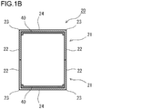
- FIGS. 1A and 1B are diagrams showing an example of a structural component.
- FIG. 1A is a perspective view of a structural component
- FIG. 1B is a cross-sectional view of an end portion of the structural component shown in FIG. 1A.
- the structural component 20 shown in FIGS. 1A and 1B includes two press-formed products 21 having a U-shaped cross-sectional shape.
- Each press-formed product 21 includes a plate portion 24 and flange portions 22 respectively connected to both ends of the plate portion 24.
- the flange portions 22 of the two press-formed products 21 is obtained.
- Reinforcing plates 40 are welded to both end portions in the longitudinal direction on the back surfaces of the two plate portions 24 and the four ridge line portions 23 of the structural component 20.
- the strength of the structural component 20 is strengthened only at both ends in the longitudinal direction. Therefore, it cannot be said that the strength of the structural component 20 is sufficiently improved.
- a reinforcing plate 40 when manufacturing a structural component 20 having a partially reinforced region, such as the structural component 20 shown in FIGS. 1A and 1B, a reinforcing plate 40 must be welded to the reinforced region. If it does so, in order to strengthen the intensity
- the present invention has been made in view of the above circumstances.
- the objective of this invention is providing the manufacturing method which can manufacture smoothly the metal plate with a protruding item
- Another object of the present invention is to provide a metal plate with ridges suitable for manufacturing the structural component and a structural component using the metal plate with ridges.
- a method of manufacturing a metal plate according to an embodiment of the present invention uses a rolling mill equipped with a roll stand, and a metal with ridges having one or more ridges formed along the rolling direction on the upper and lower surfaces.
- the manufacturing method includes a preparation process, an assembling process, and a molding process.
- a grooved roll is prepared in which one or more grooves are provided on the outer peripheral surface along the circumferential direction.
- a grooved roll is incorporated as an upper roll and a lower roll of a roll stand.
- the material to be rolled is rolled by a rolling mill in which a grooved roll is incorporated, and a metal plate with ridges on which ridges are formed corresponding to each groove of the grooved roll is formed.
- the arrangement of the grooves in the longitudinal section of the grooved roll is symmetrical.
- At least one of the groove arrangement in the longitudinal section of the grooved roll incorporated as an upper roll and the groove arrangement in the longitudinal section of the grooved roll incorporated as a lower roll is at least one. It can be set as the structure which does not overlap in a part.
- the shape of each groove in the longitudinal section of the grooved roll may be a rectangle, a trapezoid or a V shape.
- the groove width of the grooved roll may be larger than 5 mm and smaller than 2000 mm.
- the pitch of the grooves in the grooved roll may be greater than 15 mm and smaller than 2000 mm.
- the metal plate with ridges is a metal plate having one or more ridges formed on the upper surface and the lower surface.
- the pitch of the ridges is larger than 15 mm and smaller than 2000 mm.
- a plate thickness ratio (t / tmin) between the ridge plate thickness t represented by the sum of the minimum plate thickness tmin and the height h of the ridge and the minimum plate thickness tmin (t / tmin) is larger than 1.0 and from 10.0 Is also small.
- the width of each ridge may be larger than 5 mm and smaller than 2000 mm.
- the structural component according to the embodiment of the present invention is a structural component having protrusions on the front surface and the back surface.
- the structural component has a reinforcing region that requires a partial strength, and protrusions are arranged on the front and back surfaces of the reinforcing region.
- a metal plate with ridges can be produced smoothly.
- This metal plate with ridges is provided with one or more ridges along the rolling direction on both the upper surface and the lower surface. Therefore, when manufacturing the structural part which has a reinforcement area
- the metal plate with ridges according to the present invention is suitable for a material of a structural part that partially has a reinforcing region.
- FIG. 1A is a perspective view showing an example of a structural component.
- 1B is a cross-sectional view of the end of the structural component shown in FIG. 1A.
- Drawing 2 is a mimetic diagram showing an example of a manufacturing equipment line used for manufacture of a metal plate with a ridge by an embodiment of the present invention.
- FIG. 3 is a cross-sectional view showing an example of a roll stand in which a grooved roll according to an embodiment of the present invention is incorporated.
- FIG. 4 is a perspective view showing a metal plate with ridges manufactured by a finish rolling mill including the roll stand shown in FIG. 3.
- FIG. 5 is a cross-sectional view schematically showing an example of a metal plate with ridges.
- FIG. 1A is a perspective view showing an example of a structural component.
- 1B is a cross-sectional view of the end of the structural component shown in FIG. 1A.
- Drawing 2 is a mimetic diagram showing an example of a manufacturing equipment line
- FIG. 6 is a cross-sectional view schematically showing an example of a metal plate with ridges.
- FIG. 7 is a cross-sectional view schematically showing an example of a metal plate with ridges.
- FIG. 8 is a cross-sectional view schematically showing an example of a metal plate with ridges.
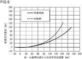
- FIG. 9 is a diagram illustrating an example of a state of warpage that occurs in a roll stand in which a grooved roll is incorporated.
- FIG. 10 is a cross-sectional view showing an example of a blank cut out from a metal plate with ridges in order to manufacture a structural component according to an embodiment of the present invention.
- FIG. 11A is a cross-sectional view schematically showing an example of an apparatus for press-molding the blank shown in FIG.
- FIG. 11B is a cross-sectional view of a press-formed product formed by the apparatus shown in FIG. 11A.
- 12A is a cross-sectional view schematically showing another example of an apparatus for press-molding the blank shown in FIG. 10 into a structural part.
- 12B is a cross-sectional view of a press-formed product formed by the apparatus shown in FIG. 12A.
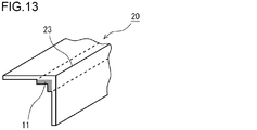
- FIG. 13 is a schematic diagram illustrating an example of a structural component.
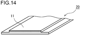
- FIG. 14 is a schematic diagram illustrating an example of a structural component.
- FIG. 15 is a schematic diagram illustrating an example of a structural component.
- FIG. 16 is a schematic diagram illustrating an example of a structural component.
- FIG. 17 is a schematic diagram illustrating an example of a structural component.
- FIG. 18 is a schematic diagram illustrating an example of a structural component.
- FIG. 19 is a schematic diagram illustrating an example of a structural component.
- FIG. 20 is a schematic diagram illustrating an example of a structural component.
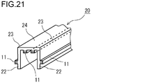
- FIG. 21 is a schematic diagram illustrating an example of a structural component.
- FIG. 22 is a schematic diagram illustrating an example of a structural component.
- Drawing 2 is a mimetic diagram showing an example of a manufacturing equipment line used for manufacture of a metal plate with a ridge by an embodiment of the present invention.
- the case where the steel plate 10 with a ridge is manufactured as a metal plate with a ridge is illustrated. That is, the case where the steel slab 30 is applied as a raw material of a metal plate with a ridge is illustrated.
- the heating furnace 1 heats the slab 30.
- the heated slab 30 is first conveyed to the roughing mill 2.
- the rough rolling machine 2 rolls the slab 30 and forms a long steel sheet 31 having a thickness of about 50 mm, for example.
- the steel sheet 31 is conveyed to the finish rolling mill 3.
- the finish rolling mill 3 includes six roll stands S1 to S6 (hereinafter also simply referred to as “stands”) that are sequentially connected.
- the steel sheet 31 is rolled through the stands S1 to S6 in order and formed into a steel plate 10 having a desired thickness. That is, the steel sheet 31 is a material to be rolled in the finish rolling mill 3.
- the steel plate 10 is continuously cooled via the cooling device 4 and wound up in a coil shape by the winder 5.
- Each stand S1 to S6 of the finish rolling mill 3 includes a pair of rolls 6 and 7 (work rolls) on the top and bottom, and further includes a backup roll that is paired with each of the upper roll 6 and the lower roll 7.
- Each of the stands S1 to S6 is provided with a roll axis adjusting mechanism (not shown).
- Each roll axis adjusting mechanism adjusts the mutual distance between the axis of the upper roll 6 and the axis of the lower roll 7.
- the roll axis adjustment mechanism enables adjustment of the rolling reduction ratio by the upper roll 6 and the lower roll 7 in each of the stands S1 to S6.
- Each stand S1 to S6 is provided with a load cell (not shown). Each load cell measures the rolling load by the upper roll 6 and the lower roll 7. Each load cell makes it possible to monitor the rolling load at each of the stands S1 to S6. In addition, each load cell can detect when the tip of the steel sheet 31 reaches each of the stands S1 to S6 (when the tip of the steel sheet 31 is caught in the gap between the upper roll 6 and the lower roll 7). Become.
- the detection of whether or not the tip of the steel sheet 31 has reached the stand without reduction may be made by using the output of the load cell provided in the reduction execution stand preceding the stand without reduction. Specifically, the load cell detects that the tip of the steel sheet 31 has reached the rolling reduction stand, and the elapsed time from the detection time is measured. Based on the elapsed time, the theoretical travel speed of the rolled material due to the rolling of the rolling reduction stand, and the distance between the roll axis of the rolling reduction stand and the roll axis of the next rolling reduction stand, the steel sheet is placed on the rolling reduction stand. The point in time when the tip of 31 has reached can be calculated.
- a sensor for detecting the passage of the tip of the steel sheet 31 may be provided in each of the stands S1 to S6.
- a grooved roll which will be described in detail later, is incorporated into one specific roll stand selected from the roll stands S1 to S6 of the finish rolling mill 3.
- the specific stand is selected according to the rolling ability (eg, rolling load, rolling reduction, etc.) of each of the stands S1 to S6.
- a grooved roll is incorporated in the fourth stand S4, which is two stages before the final sixth stand S6.
- the stand in which the grooved roll is to be incorporated is not particularly limited. Any of the subsequent stages of the stand in which the grooved roll is incorporated becomes a stand without reduction, and the roll incorporated in the stand without reduction functions as a transport roll.
- FIG. 3 is a cross-sectional view showing an example of a roll stand in which a grooved roll according to an embodiment of the present invention is incorporated.
- FIG. 4 is a perspective view showing a metal plate with ridges manufactured by a finish rolling mill including the roll stand shown in FIG. 3.
- a grooved roll 8 is incorporated as each of the upper roll 6 and the lower roll 7 of the specific stand (fourth stand S4 shown in FIG. 2).
- a normal flat roll is incorporated in a stand other than the specific stand.
- the outer peripheral surface of the grooved roll 8 is provided with one or a plurality of grooves 9 (hereinafter also referred to as “roll grooves”) along the circumferential direction.
- the grooved roll 8 as the upper roll 6 shown in FIG. 3 shows a mode in which two roll grooves 9 are provided at both ends.
- the grooved roll 8 as the lower roll 7 shown in FIG. 3 shows a mode in which two roll grooves 9 are provided at the center.
- the steel sheet 31 is rolled by the finish rolling mill 3 in which the grooved roll 8 is incorporated. Thereby, the protruding item
- the ridges 11 are continuous in the rolling direction of the steel plate 10. As shown in FIGS. 3 and 4, since the grooved roll 8 is incorporated as the upper roll 6 and the lower roll 7, the ridges 11 are formed on both the upper surface and the lower surface of the steel plate 10.
- the shape of the roll groove 9 in the longitudinal section of the grooved roll 8 is rectangular, trapezoidal or V-shaped.
- the rectangle, trapezoid, or V shape mentioned here allows a slight deformation and includes a combination of curves.
- the arrangement of the roll grooves 9 in the longitudinal section of the grooved roll 8 is preferably symmetrical.
- the left and right are directions along the axial direction of the grooved roll 8, and correspond to a width direction perpendicular to the rolling direction of the steel sheet 10.
- the rolling state by the grooved rolls 8 becomes uneven on the left and right. For this reason, the steel plate 10 is likely to be skewed to the left or right, which may cause operational troubles.
- the arrangement of the roll grooves 9 is bilaterally symmetrical, the rolling state by the grooved rolls 8 becomes equal on the left and right. Therefore, the steel plate 10 goes straight in the rolling direction, and no operation trouble due to the skew of the steel plate 10 occurs.
- the arrangement of the roll grooves 9 in the longitudinal section of the grooved roll 8 incorporated as the upper roll 6 and the arrangement of the roll grooves 9 in the longitudinal section of the grooved roll 8 incorporated as the lower roll 7 are as shown in FIG. It does not have to overlap at all, or it does not have to overlap partly. Further, the arrangement of the upper and lower roll grooves 9 may be completely overlapped.
- the width w1 of the roll groove 9 matches the width of the ridges 11 in the steel plate 10.
- the pitch of the roll grooves 9 adjacent to each other matches the pitch p of the ridges 11 in the steel plate 10.
- the depth of the roll groove 9 coincides with the height h of the ridge 11.
- the region of the minimum plate thickness tmin in the steel plate 10 is formed by the reduction of the region without the roll groove 9 of the roll with groove (hereinafter, “region without roll groove”) and the flat roll. That is, the minimum plate thickness tmin in the steel plate 10 is the minimum plate thickness in a region where the ridges 11 are not present.
- the width w ⁇ b> 2 of the no-roll groove region matches the width of the recesses 12 (hereinafter also referred to as “interprotrusion recesses”) between the adjacent protrusions 11 in the steel plate 10.
- the dimensions (including the number, cross-sectional shape, etc.) relating to the roll grooves 9 and the ridges 11 are basically the design of a structural part (press-formed product) manufactured using the steel plate 10 with ridges. It is determined according to the dimensions. For the determination, the capacity of the finish rolling mill 3, the effective length of the roll (practically 2000 mm at the maximum), and the like are taken into consideration. Furthermore, in the determination, the formability of a press-formed product made of the steel plate 10 with ridges is also taken into consideration.
- the width w1 of the roll groove 9 (that is, the width of the ridge 11) can be made larger than 5 mm and smaller than 2000 mm.
- the width w1 of the roll groove 9 is preferably 10 mm or more, and more preferably 20 mm or more. This is because the width of the reinforcing region of the structural part manufactured using the steel plate 10 with the ridges is secured, and the strength of the structural part is secured.
- the width w1 of the roll groove 9 is preferably 1000 mm or less, more preferably 500 mm or less. This is to reduce the weight of the structural component manufactured using the steel plate 10 with ridges.
- the pitch of the roll grooves 9 (that is, the pitch p of the ridges 11) can be larger than 15 mm and smaller than 2000 mm.
- the pitch of the roll grooves 9 is preferably larger than 20 mm. This is because the width w1 of the roll groove 9 (that is, the width of the ridges 11) is secured, and as a result, the strength of the structural component manufactured using the steel plate 10 with the ridges is secured.
- the pitch of the roll grooves 9 is preferably 500 mm or less, and more preferably 200 mm or less. The reason is as follows.
- the width of the roll grooves 9 that is, the width of the ridges 11
- the width w2 of the non-roll groove region becomes large.
- the width of the region of the minimum plate thickness tmin in the steel plate 10 is increased.
- region of the minimum board thickness tmin becomes easy to deform
- Thickness ratio between the ridge plate thickness t (tmin + h) represented by the sum of the minimum plate thickness tmin and the height h of the ridge 11 (that is, the depth of the roll groove 9) in the steel plate 10 and the minimum plate thickness tmin ( t / tmin) can be larger than 1.0 and smaller than 10.0.
- the plate thickness ratio (t / tmin) is preferably 1.2 or more. This is because the height h of the ridges 11 is ensured, and as a result, the strength of the structural parts manufactured using the steel plate 10 with ridges is ensured.
- the plate thickness ratio (t / tmin) is preferably less than 4.0. This is because if the plate thickness ratio (t / tmin) is too large, the rolling reduction by the grooved roll 8 becomes excessive.
- the minimum thickness tmin of the steel plate 10 with ridges is not particularly limited, but is practically about 0.6 to 10 mm.
- FIGS. 5 to 8 are cross-sectional views schematically showing other examples of the metal plate with ridges.
- a steel plate 10 shown in FIGS. 5 to 7 includes a plurality of ridges 11 on the upper and lower surfaces thereof.
- the steel plate 10 shown in FIG. 8 includes one ridge 11 on its upper surface and a plurality of ridges 11 on its lower surface.
- the arrangement of the ridges 11 shown in FIGS. 5, 6 and 8 is bilaterally symmetric, and the arrangement of the ridges 11 shown in FIG. 7 is asymmetrical.
- the steel sheet 31 is used using the finishing rolling mill 3 in which the grooved roll 8 is incorporated as the upper roll 6 and the flat roll is incorporated as the lower roll 7 in the specific stand (fourth stand S4 shown in FIG. 2).
- the trouble shown below will generate
- the steel sheet 31 immediately after being squeezed by the roll is more likely to be in close contact with the grooved roll 8 as the upper roll 6 than the flat roll as the lower roll 7. This is because the steel sheet 31 bites into the roll groove 9. Thereby, upward force acts on the steel sheet 31 which passed the specific stand.
- the tip end portion of the steel sheet 31 is greatly warped upward.
- the tip end of the steel sheet 31 that is greatly warped is wound around the grooved roll 8 or collides with the stand without entering the gap between the rolls of the next stand.
- the grooved roll 8 is incorporated in both the upper roll 6 and the lower roll 7 of the specific stand. Then, in the specific stand, the steel sheet 31 immediately after being squeezed by the roll adheres not only to the grooved roll 8 as the upper roll 6 but also to the grooved roll 8 as the lower roll 7. Therefore, the upward force acting on the front end portion of the steel sheet 31 is relaxed until the front end of the steel sheet 31 reaches the next stand of the specific stand. Thereby, the curvature of the front-end
- the maximum rolling reduction A here is expressed by the following formula (1).
- A (t0 ⁇ t1) / t0 ⁇ 100 [%] (1)
- t0 shows the plate
- t1 shows the minimum plate
- the required value of the maximum rolling reduction of the specific stand is preferably 10 to 80%.
- the required value is more preferably 20 to 60%.
- FIG. 9 is a diagram showing an example of a situation of warpage occurring in a roll stand in which a grooved roll is incorporated.
- an analytical model in which a grooved roll is incorporated in both the upper roll and the lower roll of a specific stand is prepared, and an FEM analysis assuming the initial stage of hot rolling is performed. It was.
- an analysis model in which a grooved roll was incorporated into the upper roll of a specific stand was produced, and the same FEM analysis was performed.
- the temperature of the material to be rolled was 1100 ° C.
- the friction coefficient ⁇ between the roll and the material to be rolled was 0.1.
- the maximum rolling reduction by the upper and lower rolls was 15%.
- tip part of a to-be-rolled material was investigated for every distance of the horizontal direction from the interaxial position of an up-and-down roll.
- the vertical displacement of the tip portion of the material to be rolled in the example of the present invention is small as compared with the comparative example. That is, the curvature of the front-end
- the above-described steel plate 10 with ridges is used as a blank for a structural part formed by pressing.
- the steel plate 10 is cut into a shape suitable for a press-formed product that becomes the structural component.
- the steel sheet 10 Prior to cutting, the steel sheet 10 is subjected to hot dip galvanizing, alloying hot dip galvanizing, electrogalvanizing, aluminum plating or the like.
- the oxide film on the surface of the steel plate 10 is removed by pickling, shot blasting, or the like.
- pickling, shot blasting, plating work, and the like may be performed on the blank cut out from the steel plate 10 as long as it is performed before the press working. Depending on the specifications of the structural parts, plating may be omitted.
- FIG. 10 is a cross-sectional view showing an example of a blank cut out from a metal plate with ridges in order to manufacture a structural component according to an embodiment of the present invention.
- 11A and 11B are cross-sectional views schematically showing an example of a situation in which the blank shown in FIG. 10 is press-molded into a structural part.
- FIG. 11A shows a press molding apparatus
- FIG. 11B shows a press molded product as a structural part
- 12A and 12B are cross-sectional views schematically showing another example of a situation in which the blank shown in FIG. 10 is press-molded into a structural part.
- FIG. 12A shows a press molding apparatus
- FIG. 12B shows a press molded product that is a structural part.
- the case where the above-mentioned steel plate 10 with a ridge is applied as a metal plate with a ridge is illustrated.
- the blank 15 is cut out from the steel plate 10.
- the steel plate 10 is cut in the longitudinal direction (the direction in which the ridges 11 extend), and is also cut in the width direction (a direction perpendicular to the direction in which the ridges 11 extend).
- the cutting position is determined according to the specifications of the structural component.
- the press-formed product 21 shown in FIGS. 11B and 12B has a U-shaped cross-sectional shape.
- a rectangular tubular structural component is manufactured (see FIGS. 1A and 1B).
- the reinforcing regions that require partial strength are the plate portion 24 and the ridge line portion 23. Therefore, when the blank 15 suitable for this press-formed product 21 is cut out from the steel plate 10, the steel plate 10 leaves the ridges 11 corresponding to the plate portions 24 and the ridge line portions 23 of the press-formed product 21. It is cut at the position of the recess 12.
- the blank 15 can be formed into a press-formed product 21 by a press process using a simple punch 51 and a die 52.
- a simple punch 51 and a die 52 since the thick strip 11 is bent, springback is likely to occur. Therefore, as shown in FIG. 12A, it is preferable to use a split punch 53.
- the split punch 53 has an independent punch shoulder portion. If a high load is applied to the ridge 11 from the punch shoulder portion during the press working, the spring back can be reduced.
- FIGS. 13 to 17 are schematic views showing other examples of structural parts.
- Each of the structural parts 20 (press-formed products 21) shown in FIGS. 13 to 17 is formed by using the blank 15 cut out from the above-described steel plate 10 with ridges, and has a convex surface or back surface.
- Article 11 is provided.
- a structural component made of a steel plate with ridges is convenient in terms of improving the performance of the component, simplifying production, etc., compared with a structural component made of a steel plate having a constant plate thickness.
- the number of members can be reduced by omitting the reinforcing member.
- the strength and rigidity can be improved, and the weight can be reduced.
- the reinforcing members By integrating the reinforcing members, it is possible to omit joining steps such as welding and screwing. By integrating the reinforcing member, the entire surface area of the reinforcing member is smaller than that of the separate reinforcing member, and the rust prevention ability can be improved.
- the structural component 20 shown in FIG. 13 has an L-shaped cross-sectional shape, and the ridges 11 are arranged on the back surface of the ridge line portion 23. In this case, since the ridge line portion 23 is strengthened over the entire region in the longitudinal direction, the strength of the structural component 20 is improved.
- the structural component 20 shown in FIG. 14 has a generally flat plate shape, and a wide ridge 11 is arranged at the center of the surface. In this case, the strength of the structural component 20 is improved because the central region is reinforced extensively over the entire lengthwise direction.
- the structural component 20 shown in FIG. 15 has a U-shaped cross-sectional shape, and the ridges 11 are arranged on the back surface of the ridge line portion 23 including the plate portion 24.
- the plate part 24 and the ridge line part 23 are strengthened over the entire region in the longitudinal direction, the strength of the structural component 20 is improved.
- the ridges 11 are arranged at a certain distance from the bending axis (neutral axis), an increase in weight can be minimized and the cross-sectional secondary moment can be greatly strengthened.
- the structural component 20 shown in FIG. 16 has a U-shaped cross-sectional shape, and the ridges 11 are arranged on the back surface in the vicinity of the ridge line portion 23.
- the plate part 24 and the flange part 22 in the vicinity of the ridge line part 23 are reinforced over the entire region in the longitudinal direction, the strength of the structural component 20 is improved.
- the convexity 11 is not bent at the time of a press work, but since the vicinity of the convexity 11 is bent, a moldability is favorable.
- the structural component 20 is a combination of a U-shaped press-formed product and a metal plate.
- the ridges 11 are arranged in the circumferential direction of the rectangular tubular structural component 20. That is, the inter-projection recesses 12 are also arranged in the circumferential direction of the rectangular tubular structural component 20.
- strength of the structural component 20 improves. Thereby, even if another part is welded to the region where the ridges 11 are arranged, the strength can be ensured. Therefore, the structural component 20 is useful for a component that requires welding with another component.
- the structural component 20 is useful for a welded component in which the overall thickness is limited due to restrictions such as weight and space.
- positioned becomes weak over the whole region of the circumferential direction.
- the structural component 20 is useful for a component for which a destructive area is intentionally designated.
- FIGS. 18 to 22 are schematic views showing other examples of the structural parts.
- Each of the structural parts 20 (press-formed products 21) shown in FIGS. 18 to 22 is formed by using the blank 15 cut out from the steel plate 10 with the ridges described above.
- the ridge 11 is provided on the surface.
- Applications of the structural component 20 shown in FIGS. 18 to 22 are the same as those of the structural component 20 shown in FIGS. 13 to 17, respectively.
- the steel plate 10 with ridges is manufactured hot by the finish rolling mill 3. Therefore, in the region of the ridges 11 having a thick plate thickness, the cooling rate is slow and the hardness tends to be low compared to other regions (regions of the ridges 12 between the ridges).
- the region of the ridges 11 By utilizing the property of the region of the ridges 11 and positioning the region of the ridges 11 in a portion where it is difficult to mold the structural part, it is possible to improve the formability.
- Table 1 below shows an example of an intensity difference between the ridge region and other regions. As shown in Table 1, the strength difference varies depending on the material (high C material or low C material) of the material to be rolled, the difference between the protruding strip thickness and the minimum strip thickness, the cooling rate, and the like. The hardness of the ridge area is always lower than the hardness of the other areas.
- the metal plate with ridges can be manufactured smoothly.
- This metal plate with ridges is provided with one or more ridges along the rolling direction on both the upper surface and the lower surface. Therefore, when manufacturing the structural part which has a reinforcement area
- the present invention is not limited to the above-described embodiment, and it goes without saying that various modifications can be made without departing from the spirit of the present invention.
- the metal plate with ridges, the material of the metal plate, and the material of the structural part formed using the metal plate are not limited to steel such as general carbon steel, high-tensile steel, stainless steel, aluminum, Copper or the like may be used.
- the method for press-molding the blank cut out from the metal plate with ridges into the structural part is not particularly limited.
- a hot stamping method in which molding and quenching are performed in a mold can be adopted.
Landscapes
- Engineering & Computer Science (AREA)
- Mechanical Engineering (AREA)
- Physics & Mathematics (AREA)
- Geometry (AREA)
- Metal Rolling (AREA)
- Bending Of Plates, Rods, And Pipes (AREA)
- Reduction Rolling/Reduction Stand/Operation Of Reduction Machine (AREA)
- Laminated Bodies (AREA)
Abstract
Description
図2は、本発明の実施形態による凸条付き金属板の製造に使用される製造設備列の一例を示す模式図である。本実施形態では、凸条付き金属板として凸条付きの鋼板10を製造する場合を例示する。つまり、凸条付き金属板の素材として鋼のスラブ30を適用する場合を例示する。
A=(t0-t1)/t0×100[%] …(1)
式(1)中、t0は、特定スタンドにおける圧下前の鋼シート31の板厚を示し、t1は圧下後の鋼板10における凸条間凹部12の最小板厚を示す。
最大圧下率の設定及び調整は、特定スタンドのロール軸間調整機構によって行われる。
上記した凸条付きの鋼板10は、プレス加工によって成形される構造部品のブランクとして用いられる。構造部品の製造にあたり、鋼板10は、構造部品となるプレス成形品に適合する形状に切断される。切断に先立ち、鋼板10には、溶融亜鉛めっき、合金化溶融亜鉛めっき、電気亜鉛めっき、アルミめっき等が施される。また、めっき施工の前に、酸洗、ショットブラスト等によって、鋼板10の表面の酸化膜が除去される。もっとも、酸洗、ショットブラスト、めっき施工等は、プレス加工の前までに実施されていればよく、鋼板10から切り出されたブランクに実施されても構わない。なお、構造部品の仕様に応じ、めっき施工が省略される場合もある。

4:冷却装置、 5:巻き取り機、
S1~S6:ロールスタンド、
6:上ロール、 7:下ロール、
8:溝付きロール、 9:溝、
10:鋼板、 11:凸条、 12:凸条間凹部、
15:ブランク、
20:構造部品、 21:プレス成形品、
22:フランジ部、 23:稜線部、 24:板部、
30:スラブ、 31:鋼シート、
51:パンチ、 52:ダイ、 53:分割型パンチ、
w1:ロール溝の幅、 w2:ロール溝無し領域の幅、
p:凸条のピッチ、 tmin:最小板厚、
h:凸条の高さ、 t:凸条板厚
Claims (9)
- ロールスタンドを備えた圧延機を用い、上面及び下面に圧延方向に沿って1つ又は複数の凸条が形成された金属板を製造する方法であって、
前記製造方法は、
外周面に円周方向に沿って1つ又は複数の溝が設けられた溝付きロールを準備する準備工程と、
ロールスタンドの上ロール及び下ロールとして溝付きロールを組み込む組込み工程と、
溝付きロールが組み込まれた圧延機によって被圧延材を圧延し、溝付きロールの各溝にそれぞれ対応して凸条が形成された凸条付き金属板を成形する成形工程と、を含む、凸条付き金属板の製造方法。 - 請求項1に記載の製造方法において、
前記溝付きロールの縦断面における前記溝の配置が左右対称である、凸条付き金属板の製造方法。 - 請求項1又は2に記載の製造方法において、
上ロールとして組み込まれた前記溝付きロールの縦断面における溝の配置と、下ロールとして組み込まれた前記溝付きロールの縦断面における溝の配置と、が少なくとも一部で重ならない、凸条付き金属板の製造方法。 - 請求項1から請求項3のいずれか1項に記載の製造方法において、
前記溝付きロールの縦断面における前記各溝の形状は、矩形、台形又はV形である、凸条付き金属板の製造方法。 - 請求項1から請求項4のいずれか1項に記載の製造方法において、
前記溝付きロールにおける前記溝の幅が5mmよりも大きくて2000mmよりも小さい、凸条付き金属板の製造方法。 - 請求項1から請求項5のいずれか1項に記載の製造方法において、
前記溝付きロールにおける前記溝のピッチが15mmよりも大きくて2000mmよりも小さい、凸条付き金属板の製造方法。 - 上面及び下面に1つ又は複数の凸条が形成された凸条付き金属板であって、
凸条のピッチが15mmよりも大きくて2000mmよりも小さく、
最小板厚tminと前記凸条の高さhの和で表わされる凸条板厚tと、最小板厚tminとの板厚比(t/tmin)が、1.0よりも大きく10.0よりも小さい、凸条付き金属板。 - 請求項7に記載の凸条付き金属板において、
前記各凸条の幅が5mmよりも大きくて2000mmよりも小さい、凸条付き金属板。 - 表面及び裏面にそれぞれ凸条を備えた構造部品であって、
部分的に強度の必要な補強領域を有し、その補強領域の表面及び裏面に凸条が配置された、構造部品。
Priority Applications (9)
| Application Number | Priority Date | Filing Date | Title |
|---|---|---|---|
| JP2016552833A JPWO2016056235A1 (ja) | 2014-10-09 | 2015-10-07 | 凸条付き金属板の製造方法、凸条付き金属板、及び構造部品 |
| US15/512,911 US20170291203A1 (en) | 2014-10-09 | 2015-10-07 | Method for producing metal sheet with raised lines, metal sheet with raised lines, and structural component |
| BR112017005936A BR112017005936A2 (pt) | 2014-10-09 | 2015-10-07 | método para produção de chapa metálica com linhas elevadas, chapa metálica com linhas elevadas, e componente estrutural |
| MX2017004571A MX2017004571A (es) | 2014-10-09 | 2015-10-07 | Metodo para la produccion de una lamina de metal con lineas realzadas, lamina de metal con lineas realzadas y componente estructural. |
| CN201580054825.4A CN106794496A (zh) | 2014-10-09 | 2015-10-07 | 带凸条金属板的制造方法、带凸条金属板以及结构零件 |
| KR1020177012102A KR20170065628A (ko) | 2014-10-09 | 2015-10-07 | 돌출 릿지부를 갖는 금속판의 제조 방법, 돌출 릿지부를 갖는 금속판, 및 구조 부품 |
| EP15848236.4A EP3205414A4 (en) | 2014-10-09 | 2015-10-07 | Method for producing metal plate with protruding ridge, metal plate with protruding ridge, and structural component |
| RU2017115664A RU2677394C2 (ru) | 2014-10-09 | 2015-10-07 | Способ изготовления металлического листа с гребнями, металлический лист с гребнями и конструктивный элемент |
| CA2961129A CA2961129C (en) | 2014-10-09 | 2015-10-07 | Method for producing metal sheet with raised lines, metal sheet with raised lines, and structural component |
Applications Claiming Priority (6)
| Application Number | Priority Date | Filing Date | Title |
|---|---|---|---|
| JP2014-208072 | 2014-10-09 | ||
| JP2014208072 | 2014-10-09 | ||
| JP2014-208073 | 2014-10-09 | ||
| JP2014208073 | 2014-10-09 | ||
| JP2015051992 | 2015-03-16 | ||
| JP2015-051992 | 2015-03-16 |
Publications (1)
| Publication Number | Publication Date |
|---|---|
| WO2016056235A1 true WO2016056235A1 (ja) | 2016-04-14 |
Family
ID=55652870
Family Applications (2)
| Application Number | Title | Priority Date | Filing Date |
|---|---|---|---|
| PCT/JP2015/005092 Ceased WO2016056234A1 (ja) | 2014-10-09 | 2015-10-07 | 凸条付き金属板の製造方法、凸条付き金属板、及び構造部品 |
| PCT/JP2015/005093 Ceased WO2016056235A1 (ja) | 2014-10-09 | 2015-10-07 | 凸条付き金属板の製造方法、凸条付き金属板、及び構造部品 |
Family Applications Before (1)
| Application Number | Title | Priority Date | Filing Date |
|---|---|---|---|
| PCT/JP2015/005092 Ceased WO2016056234A1 (ja) | 2014-10-09 | 2015-10-07 | 凸条付き金属板の製造方法、凸条付き金属板、及び構造部品 |
Country Status (12)
| Country | Link |
|---|---|
| US (2) | US20170291203A1 (ja) |
| EP (2) | EP3205415B1 (ja) |
| JP (2) | JP6399098B2 (ja) |
| KR (3) | KR20170065628A (ja) |
| CN (2) | CN106794495B (ja) |
| BR (2) | BR112017006007A2 (ja) |
| CA (2) | CA2961129C (ja) |
| ES (1) | ES2805749T3 (ja) |
| MX (2) | MX384130B (ja) |
| RU (2) | RU2681235C2 (ja) |
| TW (2) | TWI642493B (ja) |
| WO (2) | WO2016056234A1 (ja) |
Cited By (1)
| Publication number | Priority date | Publication date | Assignee | Title |
|---|---|---|---|---|
| JP2018053288A (ja) * | 2016-09-27 | 2018-04-05 | 新日鐵住金株式会社 | 凸条付き溶融亜鉛系めっき鋼板およびその製造方法と、ホットスタンプ成形体 |
Families Citing this family (9)
| Publication number | Priority date | Publication date | Assignee | Title |
|---|---|---|---|---|
| CN110170530B (zh) * | 2019-05-29 | 2020-06-16 | 巨江电源科技有限公司 | 极板生产工艺 |
| CN112222208B (zh) * | 2020-10-08 | 2021-11-30 | 太原科技大学 | 一种复杂高筋薄板的轧制成型方法 |
| CN112317537B (zh) * | 2020-10-26 | 2022-03-29 | 太原科技大学 | 一种复杂高筋薄板的轧制成形工艺 |
| US12030101B2 (en) | 2021-08-12 | 2024-07-09 | Microsoft Technology Licensing, Llc | Variable thickness extruded mobile device enclosure covers |
| CN114101450A (zh) * | 2021-11-08 | 2022-03-01 | 厦门海辰新能源科技有限公司 | 辊压设备 |
| CN114309060A (zh) * | 2022-01-04 | 2022-04-12 | 刘淑容 | 碾压成型设备和物料生产线 |
| CN115740013B (zh) * | 2022-11-18 | 2025-11-04 | 东北大学 | 一种q345级薄规格高密度高纵筋钢板单道次热轧方法 |
| CN116371991B (zh) * | 2023-03-31 | 2025-09-16 | 广东利元亨智能装备股份有限公司 | 辊压装置及其控制方法、极片输送设备和模切机 |
| CN120772354A (zh) * | 2025-07-09 | 2025-10-14 | 江门市厚普精密制造有限公司 | 金属板带轧制设备及加工方法 |
Citations (3)
| Publication number | Priority date | Publication date | Assignee | Title |
|---|---|---|---|---|
| JPS58159901A (ja) * | 1982-03-17 | 1983-09-22 | Hitachi Cable Ltd | 異形断面条の製造方法 |
| US4433565A (en) * | 1978-03-30 | 1984-02-28 | Theodor Wuppermann Gmbh | Method of and apparatus for the manufacturing of metal profile members, especially steel profile members |
| JPH08197106A (ja) * | 1995-01-26 | 1996-08-06 | Kawasaki Steel Corp | 突起付き鋼板の圧延方法 |
Family Cites Families (20)
| Publication number | Priority date | Publication date | Assignee | Title |
|---|---|---|---|---|
| JPS6049801A (ja) | 1983-08-31 | 1985-03-19 | Nippon Steel Corp | 異形断面熱延鋼板の製造法 |
| JPS61116319A (ja) * | 1984-11-12 | 1986-06-03 | Yokogawa Electric Corp | ホログラムを用いた光走査装置 |
| JPS61119319A (ja) * | 1985-08-30 | 1986-06-06 | Nippon Kokan Kk <Nkk> | 片面突起つき鋼板圧延時の板反り防止方法 |
| JPS63104703A (ja) * | 1986-10-23 | 1988-05-10 | Nippon Steel Corp | 異径ロ−ル圧延における先端反り防止方法 |
| JPH01262003A (ja) * | 1988-04-14 | 1989-10-18 | Sumitomo Metal Ind Ltd | 突起付鋼材及びその圧延方法 |
| JP3147206B2 (ja) | 1994-01-24 | 2001-03-19 | 川崎製鉄株式会社 | 連続圧延機の走間板厚変更方法 |
| JPH08174129A (ja) | 1994-12-21 | 1996-07-09 | Aichi Steel Works Ltd | 異形形材の製造方法及び装置 |
| JP2005324206A (ja) | 2004-05-12 | 2005-11-24 | Daido Steel Co Ltd | 異形断面帯鋼の製造方法 |
| DE102007049062B3 (de) * | 2007-10-12 | 2009-03-12 | Siemens Ag | Betriebsverfahren zum Einbringen eines Walzguts in ein Walzgerüst eines Walzwerks, Steuereinrichtung und Walzwerk zum Walzen eines bandförmigen Walzgutes |
| US8284652B2 (en) * | 2008-10-28 | 2012-10-09 | Qualcomm Incorporated | Enhanced forward link transmission |
| RU2445179C2 (ru) * | 2010-06-16 | 2012-03-20 | Общество с ограниченной ответственностью "Северсталь-Проект" (ООО "Северсталь-Проект") | Способ горячей прокатки полос с односторонним рифлением |
| CN201776288U (zh) * | 2010-08-10 | 2011-03-30 | 新疆八一钢铁股份有限公司 | 热轧板粗轧机万向轴扁头衬板结构 |
| JP5779875B2 (ja) | 2010-12-21 | 2015-09-16 | Jfeスチール株式会社 | トーションビームの製造方法 |
| EP2468493A1 (de) * | 2010-12-23 | 2012-06-27 | Boegli-Gravures S.A. | Vorrichtung zum Prägen von Folien |
| CN102179697B (zh) | 2011-03-25 | 2012-12-12 | 无锡凯博易机电科技有限公司 | 多孔微通道扁管的辊弯成形制造方法及设备 |
| DE102011078150A1 (de) * | 2011-06-08 | 2012-12-13 | Sms Siemag Ag | Verfahren, Computerprogramm und Walzstraße zum Walzen eines Metallbandes |
| CN202290733U (zh) * | 2011-10-19 | 2012-07-04 | 无锡市锡州冷拉型钢有限公司 | 一种型钢冷轧辊 |
| JP2013189173A (ja) | 2012-03-15 | 2013-09-26 | Nippon Steel & Sumitomo Metal Corp | 自動車車体用構造部材およびその製造方法 |
| JP5916127B2 (ja) | 2012-11-06 | 2016-05-11 | 本田技研工業株式会社 | 自動車の車体構造 |
| CN203725492U (zh) * | 2014-03-31 | 2014-07-23 | 重庆钢铁(集团)有限责任公司 | 粗中轧轧辊机构 |
-
2015
- 2015-10-07 BR BR112017006007A patent/BR112017006007A2/pt not_active Application Discontinuation
- 2015-10-07 RU RU2017115660A patent/RU2681235C2/ru not_active IP Right Cessation
- 2015-10-07 JP JP2016552832A patent/JP6399098B2/ja active Active
- 2015-10-07 US US15/512,911 patent/US20170291203A1/en not_active Abandoned
- 2015-10-07 ES ES15849471T patent/ES2805749T3/es active Active
- 2015-10-07 EP EP15849471.6A patent/EP3205415B1/en active Active
- 2015-10-07 JP JP2016552833A patent/JPWO2016056235A1/ja active Pending
- 2015-10-07 MX MX2017004572A patent/MX384130B/es unknown
- 2015-10-07 WO PCT/JP2015/005092 patent/WO2016056234A1/ja not_active Ceased
- 2015-10-07 RU RU2017115664A patent/RU2677394C2/ru not_active IP Right Cessation
- 2015-10-07 CA CA2961129A patent/CA2961129C/en not_active Expired - Fee Related
- 2015-10-07 MX MX2017004571A patent/MX2017004571A/es unknown
- 2015-10-07 CN CN201580054820.1A patent/CN106794495B/zh active Active
- 2015-10-07 US US15/512,848 patent/US10603702B2/en active Active
- 2015-10-07 CN CN201580054825.4A patent/CN106794496A/zh active Pending
- 2015-10-07 BR BR112017005936A patent/BR112017005936A2/pt not_active Application Discontinuation
- 2015-10-07 EP EP15848236.4A patent/EP3205414A4/en not_active Withdrawn
- 2015-10-07 KR KR1020177012102A patent/KR20170065628A/ko not_active Ceased
- 2015-10-07 KR KR1020177012103A patent/KR102192629B1/ko active Active
- 2015-10-07 CA CA2961196A patent/CA2961196C/en not_active Expired - Fee Related
- 2015-10-07 WO PCT/JP2015/005093 patent/WO2016056235A1/ja not_active Ceased
- 2015-10-07 KR KR1020197028123A patent/KR20190112837A/ko not_active Withdrawn
- 2015-10-08 TW TW104133222A patent/TWI642493B/zh not_active IP Right Cessation
- 2015-10-08 TW TW104133220A patent/TWI616242B/zh not_active IP Right Cessation
Patent Citations (3)
| Publication number | Priority date | Publication date | Assignee | Title |
|---|---|---|---|---|
| US4433565A (en) * | 1978-03-30 | 1984-02-28 | Theodor Wuppermann Gmbh | Method of and apparatus for the manufacturing of metal profile members, especially steel profile members |
| JPS58159901A (ja) * | 1982-03-17 | 1983-09-22 | Hitachi Cable Ltd | 異形断面条の製造方法 |
| JPH08197106A (ja) * | 1995-01-26 | 1996-08-06 | Kawasaki Steel Corp | 突起付き鋼板の圧延方法 |
Non-Patent Citations (1)
| Title |
|---|
| See also references of EP3205414A4 * |
Cited By (1)
| Publication number | Priority date | Publication date | Assignee | Title |
|---|---|---|---|---|
| JP2018053288A (ja) * | 2016-09-27 | 2018-04-05 | 新日鐵住金株式会社 | 凸条付き溶融亜鉛系めっき鋼板およびその製造方法と、ホットスタンプ成形体 |
Also Published As
Similar Documents
| Publication | Publication Date | Title |
|---|---|---|
| JP6399098B2 (ja) | 凸条付き金属板の製造方法、凸条付き金属板、及び構造部品 | |
| JP4453771B2 (ja) | T形鋼の製造方法および圧延設備列 | |
| JP6683093B2 (ja) | 凸条付き溶融亜鉛系めっき鋼板およびその製造方法と、ホットスタンプ成形体 | |
| EP3970873B1 (en) | Press-forming method | |
| TW201827136A (zh) | 變厚度式金屬板的製造方法、壓制部件的製造方法及加工機 | |
| EP3165297B1 (en) | Bending method | |
| JP7127729B2 (ja) | 鋼矢板の製造方法及び鋼矢板製造用の圧延設備列 | |
| TWI747459B (zh) | 方形鋼管及其製造方法、以及建築結構物 | |
| JP5332922B2 (ja) | T形鋼の矯正方法および矯正設備 | |
| JP2001276902A (ja) | 熱間圧延チャンネルの製造方法 | |
| JP5884162B2 (ja) | T形鋼の製造方法 | |
| JP2993374B2 (ja) | 山形鋼の製造方法 | |
| JP6090212B2 (ja) | 厚肉電縫管の製造方法 | |
| JP2011189388A (ja) | 凹凸模様付き異形断面条およびその製造方法 | |
| JP2005324206A (ja) | 異形断面帯鋼の製造方法 | |
| JPH10180304A (ja) | 多条あり溝付き平鋼の製造方法 | |
| JP2014024102A (ja) | 冷延鋼板の調質圧延方法 | |
| JP2003200201A (ja) | フランジを有する形材の圧延方法 |
Legal Events
| Date | Code | Title | Description |
|---|---|---|---|
| 121 | Ep: the epo has been informed by wipo that ep was designated in this application |
Ref document number: 15848236 Country of ref document: EP Kind code of ref document: A1 |
|
| ENP | Entry into the national phase |
Ref document number: 2016552833 Country of ref document: JP Kind code of ref document: A |
|
| REEP | Request for entry into the european phase |
Ref document number: 2015848236 Country of ref document: EP |
|
| WWE | Wipo information: entry into national phase |
Ref document number: 2015848236 Country of ref document: EP |
|
| ENP | Entry into the national phase |
Ref document number: 2961129 Country of ref document: CA |
|
| WWE | Wipo information: entry into national phase |
Ref document number: 15512911 Country of ref document: US |
|
| REG | Reference to national code |
Ref country code: BR Ref legal event code: B01A Ref document number: 112017005936 Country of ref document: BR |
|
| WWE | Wipo information: entry into national phase |
Ref document number: MX/A/2017/004571 Country of ref document: MX |
|
| NENP | Non-entry into the national phase |
Ref country code: DE |
|
| ENP | Entry into the national phase |
Ref document number: 20177012102 Country of ref document: KR Kind code of ref document: A |
|
| ENP | Entry into the national phase |
Ref document number: 2017115664 Country of ref document: RU Kind code of ref document: A |
|
| ENP | Entry into the national phase |
Ref document number: 112017005936 Country of ref document: BR Kind code of ref document: A2 Effective date: 20170323 |