WO2016072013A1 - スクロール圧縮機 - Google Patents
スクロール圧縮機 Download PDFInfo
- Publication number
- WO2016072013A1 WO2016072013A1 PCT/JP2014/079577 JP2014079577W WO2016072013A1 WO 2016072013 A1 WO2016072013 A1 WO 2016072013A1 JP 2014079577 W JP2014079577 W JP 2014079577W WO 2016072013 A1 WO2016072013 A1 WO 2016072013A1
- Authority
- WO
- WIPO (PCT)
- Prior art keywords
- pump
- main shaft
- scroll compressor
- lubricating oil
- oil
- Prior art date
- Legal status (The legal status is an assumption and is not a legal conclusion. Google has not performed a legal analysis and makes no representation as to the accuracy of the status listed.)
- Ceased
Links
Images





Classifications
-
- F—MECHANICAL ENGINEERING; LIGHTING; HEATING; WEAPONS; BLASTING
- F04—POSITIVE - DISPLACEMENT MACHINES FOR LIQUIDS; PUMPS FOR LIQUIDS OR ELASTIC FLUIDS
- F04C—ROTARY-PISTON, OR OSCILLATING-PISTON, POSITIVE-DISPLACEMENT MACHINES FOR LIQUIDS; ROTARY-PISTON, OR OSCILLATING-PISTON, POSITIVE-DISPLACEMENT PUMPS
- F04C18/00—Rotary-piston pumps specially adapted for elastic fluids
- F04C18/02—Rotary-piston pumps specially adapted for elastic fluids of arcuate-engagement type, i.e. with circular translatory movement of co-operating members, each member having the same number of teeth or tooth-equivalents
-
- F—MECHANICAL ENGINEERING; LIGHTING; HEATING; WEAPONS; BLASTING
- F04—POSITIVE - DISPLACEMENT MACHINES FOR LIQUIDS; PUMPS FOR LIQUIDS OR ELASTIC FLUIDS
- F04C—ROTARY-PISTON, OR OSCILLATING-PISTON, POSITIVE-DISPLACEMENT MACHINES FOR LIQUIDS; ROTARY-PISTON, OR OSCILLATING-PISTON, POSITIVE-DISPLACEMENT PUMPS
- F04C29/00—Component parts, details or accessories of pumps or pumping installations, not provided for in groups F04C18/00 - F04C28/00
- F04C29/02—Lubrication; Lubricant separation
Definitions
- the present invention relates to a scroll compressor.
- a main shaft a frame having a main bearing for supporting the upper portion of the main shaft, a sub frame having a sub bearing for supporting the lower portion of the main shaft, and a pump provided on the lower end side of the main shaft and having a pump casing.
- the pump casing is provided with a radial groove whose one end stops on the inner side of the outer diameter of the main shaft on the upper end surface and whose other end is open to the outer periphery, and the subframe is a bottom of the pump element housing portion.
- the scroll fluid compressor described in Patent Document 1 drives the pump by rotating the main shaft
- the supply amount of the lubricating oil depends on the rotational speed of the main shaft. For this reason, the supply amount of the lubricating oil increases as the rotational speed of the main shaft increases, so that an excessive amount of lubricating oil is supplied to the bearing and the swirl to increase the oil rise, and the lubricating oil supplied to the bearing and the swirl is sealed. It may be discharged outside the container. Accordingly, there is a problem that the amount of lubricating oil stored in the sealed container is reduced, and mechanical loss such as bearing damage and seizure occurs.
- the present invention has been made against the background of the above-described problems, and an object thereof is to obtain a scroll compressor capable of reducing mechanical loss and operating at high speed.
- a scroll compressor includes a sealed container having an oil reservoir, a main shaft provided inside the sealed container, a pump driven by rotation of the main shaft, and a pump provided above the pump.
- a gap is provided between the lower surface of the pump casing and the upper surface of the pump so as to communicate the low pressure portion and the high pressure portion.
- a gap is provided between the lower surface of the pump casing and the upper surface of the pump so as to communicate the low pressure portion and the high pressure portion.
- FIG. 1 is a cross-sectional view of a scroll compressor 100 according to Embodiment 1 of the present invention.
- the scroll compressor 100 includes an orbiting scroll 1, a fixed scroll 2, a frame 3, a main shaft 4, a stator 5, a rotor 6, a subframe 8, and ball bearings 9.
- the pump 10 and the oil pipe 17 are provided.
- the outer shell of the scroll compressor 100 is composed of a sealed container 100A.
- the orbiting scroll 1 is a member having a base plate 1a and spiral teeth 1b.
- the fixed scroll 2 is a member having a base plate 2a and spiral teeth 2b.
- the swing scroll 1 and the fixed scroll 2 are combined to form a compression chamber 30.
- the swing scroll 1 and the fixed scroll 2 are accommodated in a frame 3.
- the frame 3 is a member fixed to the sealed container 100A in the upper part of the sealed container 100A, and has a main bearing 3a.
- the main bearing 3a supports the upper part of the main shaft 4 rotatably.
- the main shaft 4 is a member extending in the vertical direction of the sealed container 100 ⁇ / b> A, and has a pump shaft 4 b that transmits a rotational force to the pump 10.
- the main shaft 4 is provided with an oil hole 4c through which lubricating oil is passed.
- a stator 5 and a rotor 6 are provided outside the outer surface of the main shaft 4.
- the stator 5 is a member configured in a substantially cylindrical shape, for example, and is fixed to the sealed container 100A.
- the rotor 6 is a member configured in a substantially cylindrical shape, for example, and the main shaft 4 is inserted therethrough.
- the stator 5 and the rotor 6 constitute an electric motor part of the scroll compressor 100.
- a subframe 8 is provided below the stator 5 and the rotor 6.
- the subframe 8 is a member fixed to the sealed container 100A at the lower part inside the sealed container 100A, and has a ball bearing 9.
- the ball bearing 9 supports the lower part of the main shaft 4 rotatably.
- a pump 10 is fixed to the lower end surface of the ball bearing 9.
- the pump 10 is a member that sucks the lubricating oil stored in the oil reservoir 16 and supplies the lubricating oil to each sliding portion, and is constituted by a positive displacement pump, for example.
- the pump 10 will be described in detail with reference to FIG.
- the oil sump 16 is a part where lubricating oil is stored, and is provided at the bottom of the sealed container 100A.
- An oil pipe 17 is immersed in the oil reservoir 16.
- the oil pipe 17 is configured by, for example, a cylindrical member that passes through the upper and lower surfaces.
- FIG. 2 is a cross-sectional view showing a main part of the scroll compressor 100 according to Embodiment 1 of the present invention.
- the pump 10 is provided with a low pressure part 20a and a high pressure part 20b.
- a pump cover 12 is provided below the pump 10, and a pump casing 11 is provided above the pump 10.
- the low-pressure part 20a is a space through which the lubricant before compression among the lubricant flowing through the pump 10 flows, and is provided so as to penetrate part of the upper and lower surfaces of the pump 10.
- the low pressure part 20a communicates with the suction port 13a.
- the suction port 13a is a space for allowing the lubricating oil discharged from the oil pipe 17 to pass through the low pressure portion 20a.
- the high-pressure portion 20b is a space through which the compressed lubricating oil out of the lubricating oil flowing through the pump 10 flows, and is provided so as to penetrate part of the upper and lower surfaces of the pump 10.
- the high pressure portion 20b communicates with the discharge port 13b.
- the discharge port 13b is a space for allowing the lubricating oil discharged from the high pressure portion 20b to pass through the oil hole 4c.
- the pump cover 12 is a member that covers the pump 10 and has a storage portion 12a.
- the pump cover 12 is bolted and fixed to the lower end surface of the subframe 8.
- the upper end surface of the pump cover 12 and the lower end surface of the ball bearing 9 are in contact with each other.
- An oil pipe 17 is located below the pump cover 12. By providing the oil pipe 17 at the lower part of the pump cover 12, the inside of the pump cover 12 and the inside of the oil pipe 17 communicate with each other.
- the pump casing 11 is a member housed in the housing portion 12a and is fixed by caulking the pump cover 12.
- the pump casing 11 is provided so as to face the upper surface of the pump 10.
- a gap ⁇ is provided between the pump casing 11 and the pump 10.
- a gap ⁇ is provided between the lower surface of the pump casing 11 and the upper surface of the pump 10.
- the gap ⁇ is provided on the inner side (center side) of the outer shape of the pump casing 11 so that the low pressure portion 20a and the high pressure portion 20b communicate with each other.
- the rotor 6 When power is supplied to the stator 5, the rotor 6 generates torque and rotates together with the main shaft 4 to cause the orbiting scroll 1 to revolve. As a result, the volume of the compression chamber 30 gradually decreases, and the low-temperature and low-pressure gas refrigerant is discharged as a high-temperature and high-pressure gas refrigerant.
- the pump shaft 4b rotates when the main shaft 4 rotates, and the pump 10 is driven when the pump shaft 4b rotates.
- the lubricating oil stored in the oil reservoir 16 is guided to the pump 10 through the oil pipe 17 and the suction port 13a in this order.
- the lubricating oil guided to the pump 10 is discharged from the pump 10 through the low pressure part 20a and the high pressure part 20b in this order.
- the lubricating oil supplied from the high pressure part 20b to the low pressure part 20a via the gap ⁇ is mixed with the lubricating oil pumped up through the oil pipe 17 and compressed again by the pump 10. Part of the lubricating oil that has been compressed again is supplied from the high-pressure portion 20b to the low-pressure portion 20a through the gap ⁇ . The remainder of the compressed lubricating oil is discharged from the high-pressure part 20b and supplied to each sliding part through the discharge port 13b and the oil hole 4c in this order.
- the flow path of the lubricating oil supplied from the high pressure section 20b to the low pressure section 20a is the same as the flow path of the lubricating oil supplied from the suction port 13a to the low pressure section 20a. In this way, the pressure of the lubricating oil flowing through the pump 10 decreases when the oil is discharged from the pump 10.
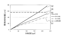
- FIG. 3 is a characteristic diagram showing the relationship between the rotational speed of the main shaft 4 of the scroll compressor 100 according to Embodiment 1 of the present invention and the amount of lubricant supplied from the pump 10.
- the horizontal axis of FIG. 3 indicates the rotational speed [rps] of the main shaft 4, and the vertical axis of FIG. 3 indicates the lubricating oil supply amount [cc / s].
- the relationship between the rotation speed of the main shaft 4 and the supply amount of the lubricating oil supplied from the pump 10 will be described with reference to FIG.
- a lubricating oil having a viscosity of 32 cst, a density of 0.9 g / cm 3 to 1.0 g / cm 3 and an oil temperature of ⁇ 20 ° C. to 80 ° C. is used.
- a scroll compressor 100 using a 0.32 cm 3 / rev one is assumed.
- FIG. 3 shows the relationship between the rotational speed of the main shaft and the lubricant supply amount in the conventional scroll compressor.
- (A) in FIG. 3 shows the amount of lubricating oil supplied required when the scroll compressor is operated.
- the supply amount of the lubricating oil when the gap ⁇ is provided is smaller than the supply amount of the lubricating oil when the gap ⁇ is not provided.
- the difference between the amount of lubricant supplied when ⁇ is provided and the amount of lubricant supplied when no gap ⁇ is not provided is not large.
- the rotational speed of the main shaft 4 increases, the difference between the supply amount of the lubricating oil when the gap ⁇ is provided and the supply amount of the lubricant oil when the gap ⁇ is not provided gradually increases.
- the flow rate of the lubricating oil supplied from the high pressure portion 20b through the gap ⁇ to the low pressure portion 20a is proportional to the flow velocity of the lubricating oil when flowing through the gap ⁇ . Further, since the flow rate of the lubricating oil when flowing through the gap ⁇ depends on the pressure of the lubricating oil, the flow rate of the lubricating oil supplied from the high pressure portion 20b to the low pressure portion 20a through the gap ⁇ is equal to the pressure generated by the pump 10. Dependent.
- the scroll compressor 100 includes, in the pump 10, the low pressure part 20a that communicates with the inside of the oil pipe 17, and the high pressure part 20b that has a higher pressure than the low pressure part 20a. , And a gap ⁇ is provided between the lower surface of the pump casing 11 and the upper surface of the pump 10 so as to communicate the low pressure portion 20a and the high pressure portion 20b. For this reason, during the operation of the scroll compressor 100, a part of the lubricating oil which has been compressed in the pump 10 and whose pressure has increased is supplied again from the high pressure part 20b to the low pressure part 20a via the gap ⁇ .
- the gap ⁇ is configured to be provided by lowering the groove provided in the storage portion 12a toward the lower end surface, but is not limited thereto.
- the gap ⁇ is provided between the lower surface of the pump casing 11 and the upper surface of the pump 10, and is configured to communicate the low pressure portion 20a and the high pressure portion 20b on the inner side (center side) of the outer shape of the pump casing 11. It only has to be.
- Embodiment 2 unlike the first embodiment, the elastic body 21 is provided without providing the gap ⁇ .
- items that are not particularly described are the same as those in the first embodiment, and the same functions and configurations are described using the same reference numerals.
- FIG. 4 is a cross-sectional view showing a main part of the scroll compressor 100 according to Embodiment 2 of the present invention.
- FIG. 5 is a cross-sectional view showing a main part of scroll compressor 100 according to Embodiment 2 of the present invention.
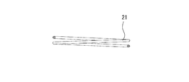
- FIG. 6 is a diagram illustrating an example of the elastic body 21 of the scroll compressor 100 according to Embodiment 2 of the present invention. The rotational speed of the main shaft 4 in FIG. 4 is smaller than the rotational speed of the main shaft 4 in FIG.
- an elastic body 21 is provided inside the sealed container 100A.
- the elastic body 21 is constituted by a coil spring having a shape as shown in FIG. 6, for example, and is provided between the pump casing 11 and the pump cover 12 and crimped.
- One end of the elastic body 21 is located on the upper surface of the pump casing 11, and the other end of the elastic body 21 is located on the lower surface of the pump cover 12.
- the elastic body 21 has a reference length.
- the reference length of the elastic body 21 is, for example, a natural length.
- the elastic body 21 In a state where the elastic body 21 has the reference length, the lower surface of the pump casing 11 and the upper surface of the pump 10 are in contact with each other, and the low pressure part 20a and the high pressure part 20b are not communicated with each other.
- the elastic body 21 expands and contracts in the axial direction of the main shaft 4.
- the pump casing 11 and the pump 10 are in contact, and specifically, the lower surface of the pump casing 11 and the upper surface of the pump 10 are in contact.
- the gap ⁇ is provided as in Embodiment 1, not only the amount of lubricating oil supplied during high-speed operation but also the amount of lubricating oil supplied during low-speed operation is reduced compared to the conventional case. In this case, the lubricating oil may not be sufficiently supplied to each sliding portion.
- the lubricating oil supply amount at the time of high-speed operation is reduced as compared with the conventional case, while the supply amount of the lubricating oil at the low-speed operation is not reduced, so that the lubricating oil at the low-speed operation is reduced. Is sufficiently supplied to each sliding portion.
- FIG. 4 has shown the direction through which lubricating oil flows.
- the same operations as those already described in the first embodiment are omitted as appropriate.
- the pump casing 11 is pressed by the elastic body 21 during low-speed operation.
- the pump casing 11 is pushed up and shown in FIG. It will be in a state to be.
- the elastic body 21 is displaced so as to contract more than the reference length, so that the pump cover 12 and the pump 10 are not displaced. Is formed with a gap ⁇ . A part of the lubricating oil moves from the high pressure part 20b to the low pressure part 20a via the gap ⁇ .
- the lubricating oil supplied from the high pressure part 20 b to the low pressure part 20 a via the gap ⁇ is mixed with the lubricating oil pumped up through the oil pipe 17 and compressed again by the pump 10.
- a part of the lubricating oil compressed again is supplied from the high pressure part 20b to the low pressure part 20a through the gap ⁇ .
- the remainder of the compressed lubricating oil is discharged from the high-pressure part 20b and supplied to each sliding part through the discharge port 13b and the oil hole 4c in this order.
- the flow path of the lubricating oil supplied from the high pressure section 20b to the low pressure section 20a via the gap ⁇ is the same as the flow path of the lubricating oil supplied from the suction port 13a to the low pressure section 20a. In this way, the pressure of the lubricating oil flowing through the pump 10 decreases when the oil is discharged from the pump 10.
- the elastic body 21 of the scroll compressor 100 will be described below.
- the elastic body 21 receives a compressive force due to the pressure in the pump 10.
- F1 can be calculated using the following (Equation 1).
- F1 P ⁇ A (Formula 1)
- P Pressure in the pump 10
- A Area of the portion where the pump casing 11 and the pump 10 are in contact with each other
- the pump casing 11 is pressed against the upper end surface of the pump 10 by the reaction force of the elastic body 21.
- the pump casing 11 is pushed upward in the axial direction of the main shaft 4 by the pressure in the pump 10.
- a gap ⁇ is formed between the pump casing 11 and the pump 10.
- the pressure P in the pump 10 can be lowered by deforming the elastic body 21 with a predetermined pressure.
- the pressure P in the pump 10 is related to the flow rate Q of the pump 10 and can be calculated using the following (Equation 4).
- P ⁇ ⁇ (Q / C ⁇ A) 2/2 ⁇ ( Equation 4)
- C Outflow coefficient ⁇ : Lubricating oil density
- the flow rate Q of the pump 10 can be calculated using the following (Formula 5).
- Q q ⁇ n (Formula 5)
- q Discharge amount of the pump 10
- n Number of rotations of the scroll compressor 100 (main shaft 4)
- the pressure P at each rotational speed of the main shaft 4 is calculated using the above-described (Formula 1) to (Formula 5), the spring constant k is calculated based on the calculated pressure P, and the material and shape of the elastic body 21 are determined. To do.
- the flow rate Q of the pump 10 can be calculated as follows using the above (Formula 5).
- the pressure P can be calculated as follows using the above-described (Formula 4).
- the outflow coefficient C is 1.
- the spring constant k can be calculated as follows using (Equation 3) described above.
- the elastic body 21 is configured with a material and a shape such that the spring constant k is within the above-described value range.
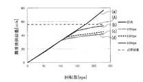
- FIG. 7 is a characteristic diagram showing the relationship between the rotational speed of the main shaft 4 of the scroll compressor 100 according to Embodiment 2 of the present invention and the supply amount of the lubricating oil supplied from the pump 10.
- the horizontal axis of FIG. 7 shows the rotational speed [rps] of the main shaft 4, and the vertical axis of FIG. 7 shows the lubricating oil supply amount [cc / s].
- the relationship between the rotation speed of the main shaft 4 and the supply amount of the lubricating oil supplied from the pump 10 will be described with reference to FIG.
- a lubricating oil having a viscosity of 32 cst, a density of 0.9 g / cm 3 to 1.0 g / cm 3 and an oil temperature of ⁇ 20 ° C. to 80 ° C. is used.
- the scroll compressor 100 is assumed to use a pump 10 having a discharge amount of 0.32 cm 3 / rev. Further, in FIG. 7, it is assumed that the scroll compressor 100 has an operating range of 10 rps to 240 rps and an area where the pump casing 11 and the pump 10 are in contact with each other is 415 mm 2 .
- FIG. 7 shows the relationship between the rotational speed of the main shaft and the lubricant supply amount in a conventional scroll compressor.
- the relationship between the rotational speed of the main shaft 4 and the lubricant supply amount is shown.
- (A) in FIG. 7 has shown the amount of lubricating oil supply requested
- the supply amount of lubricating oil in the scroll compressor 100 of the second embodiment and the conventional scroll compressor is substantially the same until the pump casing 11 is pushed up.
- the rotation speed of the main shaft 4 when the pump casing 11 is not pushed up is, for example, in the range of 10 rps to 100 rps.
- the pressure of the pump 10 increases and the pump casing 11 is pushed up.
- the pump casing 11 is pushed up when the rotational speed of the main shaft 4 exceeds 100 rps.
- the operation of the scroll compressor 100 is performed.
- a lubricating oil supply amount close to the required lubricating oil supply amount can be obtained.
- the scroll compressor 100 is attached so that one end is located on the lower surface of the pump cover 12 and the other end is located on the upper surface of the pump casing 11 and has an elastic length having a reference length.
- the pump 10 is provided with a low-pressure part 20a communicating with the inside of the oil pipe 17, and a high-pressure part 20b having a higher pressure than the low-pressure part 20a.
- the elastic body 21 is longer than the reference length.
- the lubricating oil can be sufficiently supplied to each sliding portion without reducing the amount of the lubricating oil supplied during low-speed operation. .
- the example using a coil spring was demonstrated as the elastic body 21, it is not limited to this.
- a spring spring or the like may be used as the elastic body 21.
- the specific numerical value of the rotation speed of the main shaft 4 is not limited to this.
- the structure in which the lubricating oil is moved from the high-pressure portion 20b in the pump 10 to the low-pressure portion 20a through the gap ⁇ is not limited to this.
- the discharge path 22 may be provided.
- FIG. 8 is a cross-sectional view showing a main part of the scroll compressor 100 according to Embodiment 2 of the present invention, which is a modification of FIG.
- the discharge path 22 is formed so that the lubricating oil flows out of the pump cover 12 through the gap ⁇ when the pump casing 11 is pushed up to form the gap ⁇ . .
- the discharge path 22 is provided so as to penetrate the pump cover 12 in the horizontal direction at the same height as the gap ⁇ and to communicate with the outside of the pump cover 12. As a result, the amount of lubricating oil that moves from the high-pressure portion 20b to the low-pressure portion 20a via the gap ⁇ is reduced, and the recompression loss can be improved.
- 1 swing scroll 1a base plate, 1b spiral tooth, 2 fixed scroll, 2a base plate, 2b spiral tooth, 3 frame, 3a main bearing, 4 main shaft, 4b pump shaft, 4c oil hole, 5 stator, 6 rotor, 8 Sub frame, 9 ball bearing, 10 pump, 11 pump casing, 12 pump cover, 12a storage part, 13a intake port, 13b discharge port, 16 oil reservoir, 17 oil pipe, 20a low pressure part, 20b high pressure part, 21 elastic body 22 discharge path, 30 compression chamber, 100 scroll compressor, 100A airtight container, C outflow coefficient, L height dimension, P pressure, Q flow rate, k spring constant, ⁇ , ⁇ gap.
Landscapes
- Engineering & Computer Science (AREA)
- Mechanical Engineering (AREA)
- General Engineering & Computer Science (AREA)
- Applications Or Details Of Rotary Compressors (AREA)
- Rotary Pumps (AREA)
Abstract
油溜め部16を有する密閉容器100Aと、密閉容器100Aの内部に設けられる主軸4と、主軸4が回転することで駆動されるポンプ10と、ポンプ10の上方に設けられるポンプケーシング11と、油溜め部16に溜められる潤滑油を通す油パイプ17と、を備え、ポンプ10の内部には、油パイプ17の内部と連通する低圧部20aと、低圧部20aよりも高圧となる高圧部20bと、が設けられ、ポンプケーシング11の下面とポンプ10の上面との間には、低圧部20aと高圧部20bとを連通するように空隙δが設けられている。
Description
本発明は、スクロール圧縮機に関する。
従来、「主軸と、この主軸の上部を支持する主軸受を有するフレームと、前記主軸の下部を支持する副軸受を有するサブフレームと、前記主軸の下端側に設けられ、ポンプケーシングを有するポンプを備えたスクロール流体機械において、前記ポンプケーシングは上端面に一端が前記主軸の外径より内側で止まりとし、他端が外周に開口した放射溝を備え、前記サブフレームはそのポンプ要素収納部の底側に前記放射溝と連通する環状溝及びこの環状溝に一方が開口し、他方がその下端面に開口する副軸受排油路を備え、前記主軸はその下端面を前記ポンプケーシングの上端面に当接させた」スクロール流体圧縮機があった(例えば、特許文献1参照)。
ここで、特許文献1に記載のスクロール流体圧縮機は、主軸を回転させることでポンプを駆動するようになっているため、潤滑油の供給量は主軸の回転数に依存する。このため、主軸の回転数が速くなるにつれて潤滑油の供給量も増加し、必要以上の潤滑油が軸受及び渦巻に供給されて油上りが増加し、軸受及び渦巻に供給された潤滑油が密閉容器の外部に吐出される場合がある。したがって、密閉容器の内部に貯留される潤滑油の量が減少し、軸受損傷及び焼付き等の機械損失が発生するという課題があった。
本発明は、上述のような課題を背景としてなされたものであり、機械損失を低減させ、高速運転可能なスクロール圧縮機を得ることを目的としている。
本発明に係るスクロール圧縮機は、油溜め部を有する密閉容器と、前記密閉容器の内部に設けられる主軸と、前記主軸が回転することで駆動されるポンプと、前記ポンプの上方に設けられるポンプケーシングと、前記油溜め部に溜められる潤滑油を通す油パイプと、を備え、前記ポンプの内部には、前記油パイプの内部と連通する低圧部と、前記低圧部よりも高圧となる高圧部と、が設けられ、前記ポンプケーシングの下面と前記ポンプの上面との間には、前記低圧部と前記高圧部とを連通するように空隙が設けられているものである。
本発明によれば、ポンプケーシングの下面とポンプの上面との間には、低圧部と高圧部とを連通するように空隙が設けられている。このため、スクロール圧縮機の運転時において、ポンプ内で圧縮されて圧力が上昇した潤滑油の一部は、高圧部から空隙を介して再び低圧部に供給される。したがって、密閉容器の内部に貯留される潤滑油が減少することを抑制でき、軸受損傷及び焼付き等の機械損失を低減させることができ、高速運転可能なスクロール圧縮機を得ることができる。
以下、本発明のスクロール圧縮機100について、図面を用いて詳細に説明する。なお、以下の図面では各構成部材の大きさの関係が実際のものとは異なる場合がある。また、以下の図面において、同一の符号を付したものは、同一又はこれに相当するものであり、このことは明細書の全文において共通することとする。さらに、明細書全文に表わされている構成要素の形態は、あくまでも例示であって、これらの記載に限定されるものではない。
実施の形態1.
図1は本発明の実施の形態1に係るスクロール圧縮機100の断面図である。図1に示されるように、スクロール圧縮機100は、揺動スクロール1と、固定スクロール2と、フレーム3と、主軸4と、ステータ5と、ロータ6と、サブフレーム8と、玉軸受9と、ポンプ10と、油パイプ17と、を備える。スクロール圧縮機100の外郭は、密閉容器100Aで構成される。
図1は本発明の実施の形態1に係るスクロール圧縮機100の断面図である。図1に示されるように、スクロール圧縮機100は、揺動スクロール1と、固定スクロール2と、フレーム3と、主軸4と、ステータ5と、ロータ6と、サブフレーム8と、玉軸受9と、ポンプ10と、油パイプ17と、を備える。スクロール圧縮機100の外郭は、密閉容器100Aで構成される。
揺動スクロール1は、台板1a及び渦巻歯1bを有する部材である。固定スクロール2は、台板2a及び渦巻歯2bを有する部材である。揺動スクロール1及び固定スクロール2は、組み合わされて圧縮室30を形成する。揺動スクロール1及び固定スクロール2は、フレーム3に収納されている。
フレーム3は、密閉容器100Aの内部の上部において密閉容器100Aに固定されている部材であり、主軸受3aを有する。主軸受3aは、主軸4の上部を回転可能に支持するものである。主軸4は、密閉容器100Aの上下方向に延びる部材であり、ポンプ10に回転力を伝達するポンプ軸4bを有する。主軸4には、潤滑油を通す油穴4cが設けられている。主軸4の外面よりも外側には、ステータ5及びロータ6が設けられている。
ステータ5は、例えば、略筒状に構成される部材であり、密閉容器100Aに固定されている。ロータ6は、例えば、略筒状に構成される部材であり、主軸4が挿通される。ステータ5及びロータ6は、スクロール圧縮機100の電動機部を構成する。ステータ5及びロータ6よりも下方にはサブフレーム8が設けられている。
サブフレーム8は、密閉容器100Aの内部の下部において密閉容器100Aに固定されている部材であり、玉軸受9を有する。玉軸受9は、主軸4の下部を回転可能に支持するものである。玉軸受9の下端面にはポンプ10が固定されている。
ポンプ10は、油溜め部16に溜められた潤滑油を吸引して各摺動部に潤滑油を供給する部材であり、例えば、容積型のポンプで構成される。ポンプ10については図2を用いて詳しく説明する。油溜め部16は、潤滑油が溜められる部分であり、密閉容器100Aの底部に設けられている。油溜め部16には、油パイプ17が浸漬されている。油パイプ17は、例えば、上下面が貫通する筒状の部材で構成されている。
図2は本発明の実施の形態1に係るスクロール圧縮機100の要部を示す断面図である。図2に示されるように、ポンプ10には、低圧部20a及び高圧部20bが設けられている。また、図2に示されるように、ポンプ10の下方にはポンプカバー12が設けられ、ポンプ10の上方にはポンプケーシング11が設けられている。
低圧部20aは、ポンプ10を流れる潤滑油のうち圧縮される前の潤滑油が流れる空間であり、ポンプ10の上下面の一部を貫通するように設けられる。低圧部20aは吸入ポート13aと連通している。吸入ポート13aは、油パイプ17から排出された潤滑油を低圧部20aに通すための空間である。
高圧部20bは、ポンプ10を流れる潤滑油のうち圧縮された後の潤滑油が流れる空間であり、ポンプ10の上下面の一部を貫通するように設けられる。高圧部20bは吐出ポート13bと連通している。吐出ポート13bは、高圧部20bから排出された潤滑油を油穴4cに通すための空間である。
ポンプカバー12は、ポンプ10を覆う部材であり、収納部12aを有する。ポンプカバー12は、サブフレーム8の下端面においてボルト締め固定されている。ポンプカバー12の上端面と玉軸受9の下端面とは当接している。ポンプカバー12の下部には油パイプ17が位置している。油パイプ17がポンプカバー12の下部に設けられることで、ポンプカバー12の内部と油パイプ17の内部とが連通する。
ポンプケーシング11は、収納部12aに収納されている部材であり、ポンプカバー12をカシメることで固定されている。ポンプケーシング11は、ポンプ10の上面と対向するように設けられている。ポンプケーシング11とポンプ10との間には空隙δが設けられている。具体的には、ポンプケーシング11の下面とポンプ10の上面との間には空隙δが設けられている。空隙δは、ポンプケーシング11の外形よりも内側(中心側)において、低圧部20aと高圧部20bとが連通するように設けられる。空隙δは、主軸4の軸方向におけるポンプ10の高さをLとした場合に、例えば、δ=0.04L以上0.06L以下である。
以下に、本実施の形態1のスクロール圧縮機100の作用及び潤滑油の流れについて図2を用いて説明する。なお、図2の矢印は潤滑油が流れる方向を示している。
ステータ5に給電されると、ロータ6は、トルクを発生して主軸4とともに回転し、揺動スクロール1を公転運動させる。これにより、圧縮室30の容積は順次減少していき、低温低圧のガス冷媒は高温高圧なガス冷媒となって吐出される。また、主軸4が回転することでポンプ軸4bが回転し、ポンプ軸4bが回転することでポンプ10が駆動される。これにより、油溜め部16に溜められている潤滑油が、油パイプ17、吸入ポート13aを順に通ってポンプ10に導かれる。ポンプ10に導かれた潤滑油は、低圧部20a、高圧部20bを順に通って、ポンプ10から排出される。
このとき、低圧部20aと高圧部20bとを連通するように空隙δが設けられているため、ポンプ10から排出された潤滑油の一部は、高圧部20bから空隙δを介して低圧部20aに移動する。潤滑油の一部が、高圧部20bから空隙δを通って低圧部20aに移動すると、潤滑油がポンプ10から吐出される際の潤滑油の圧力が低下し、油穴4cから排出される潤滑油の供給量が減少する。ポンプ10から排出された潤滑油の残りは、吐出ポート13bに吐出されて油穴4cに汲み上げられる。油穴4cに汲み上げられた潤滑油は、各摺動部に供給される。
高圧部20bから空隙δを介して低圧部20aに供給された潤滑油は、油パイプ17を通って汲み上げられた潤滑油と混合し、ポンプ10によって再度圧縮される。再度圧縮された潤滑油の一部は、高圧部20bから空隙δを介して低圧部20aへ供給される。再度圧縮された潤滑油の残りは、高圧部20bから排出され、吐出ポート13b、油穴4cを順に通って各摺動部へ供給される。なお、高圧部20bから低圧部20aへ供給された潤滑油の流路は、吸入ポート13aから低圧部20aへ供給された潤滑油の流路と同様である。このようにして、ポンプ10内を流れる潤滑油の圧力はポンプ10から排出される際に低下する。
図3は本発明の実施の形態1に係るスクロール圧縮機100の主軸4の回転数とポンプ10から供給される潤滑油の供給量との関係を示した特性図である。図3の横軸には主軸4の回転数[rps]を示し、図3の縦軸には潤滑油供給量[cc/s]を示している。以下に、図3を用いて、主軸4の回転数とポンプ10から供給される潤滑油の供給量との関係について説明する。
なお、図3においては、潤滑油は、粘度32cst、密度0.9g/cm3以上1.0g/cm3以下、油温-20℃以上80℃以下のものを使用し、ポンプ10は吐出量0.32cm3/revのものを使用したスクロール圧縮機100を想定している。
図3における(a)は、従来のスクロール圧縮機における主軸の回転数と潤滑油供給量との関係を示している。
また、図3における(b)は、本発明のスクロール圧縮機100においてδ=0.04Lである場合における主軸4の回転数と潤滑油供給量との関係を示している。
また、図3における(c)は、本発明のスクロール圧縮機100においてδ=0.06Lである場合における主軸4の回転数と潤滑油供給量との関係を示している。
また、図3における(A)は、スクロール圧縮機の運転に際して要求される潤滑油供給量を示している。
また、図3における(b)は、本発明のスクロール圧縮機100においてδ=0.04Lである場合における主軸4の回転数と潤滑油供給量との関係を示している。
また、図3における(c)は、本発明のスクロール圧縮機100においてδ=0.06Lである場合における主軸4の回転数と潤滑油供給量との関係を示している。
また、図3における(A)は、スクロール圧縮機の運転に際して要求される潤滑油供給量を示している。
図3に示されるように、主軸4の回転数が低い場合において、空隙δを設けたときの潤滑油の供給量は、空隙δを設けないときの潤滑油の供給量よりも小さいものの、空隙δを設けたときの潤滑油の供給量と、空隙δを設けないときの潤滑油の供給量と、の差は大きくない。一方で、主軸4の回転数が高くなるにつれて、空隙δを設けたときの潤滑油の供給量と、空隙δを設けないときの潤滑油の供給量と、の差は次第に大きくなる。
ここで、空隙δの面積が一定であるため、高圧部20bから空隙δを通って低圧部20aに供給される潤滑油の流量は、空隙δを流れる際の潤滑油の流速に比例する。また、空隙δを流れる際の潤滑油の流速は潤滑油の圧力に依存するため、高圧部20bから空隙δを通って低圧部20aに供給される潤滑油の流量はポンプ10によって発生する圧力に依存する。したがって、主軸4の回転数が増加し、ポンプ10によって発生する圧力が増加するほど、高圧部20bから空隙δを通って低圧部20aに供給される潤滑油の流量は増加する。このようにして、上述したように、主軸4の回転数が高くなるにつれて、空隙δを設けたときの潤滑油の供給量と、空隙δを設けないときの潤滑油の供給量と、の差は次第に大きくなる。
以上のように、本実施の形態1に係るスクロール圧縮機100は、ポンプ10の内部には、油パイプ17の内部と連通する低圧部20aと、低圧部20aよりも高圧となる高圧部20bと、が設けられ、ポンプケーシング11の下面とポンプ10の上面との間に、低圧部20aと高圧部20bとを連通するように空隙δを設けている。このため、スクロール圧縮機100の運転時において、ポンプ10内で圧縮されて圧力が上昇した潤滑油の一部は、高圧部20bから空隙δを介して再び低圧部20aに供給される。したがって、低速運転時に必要な潤滑油の供給量を確保しつつ、高速運転時において過剰な潤滑油の供給量を抑制することができる。このようにして、機械損失を低減させることができ、高速運転可能なスクロール圧縮機100を得ることができる。そして、スクロール圧縮機100の運転条件次第では、240rpsの高速運転であっても運転を行うことができる。
なお、本実施の形態1においては、空隙δは、収納部12aに設けられる溝を下端面側に下げることで設けられるように構成しているが、これに限定されない。空隙δは、ポンプケーシング11の下面とポンプ10の上面との間に設けられ、ポンプケーシング11の外形よりも内側(中心側)において、低圧部20aと高圧部20bとを連通させるように構成されていればよい。
実施の形態2.
本実施の形態2においては、実施の形態1とは異なり、空隙δを設けないで弾性体21を設けるようにしたものである。なお、本実施の形態2において、特に記述しない項目については実施の形態1と同様とし、同一の機能や構成については同一の符号を用いて述べることとする。
本実施の形態2においては、実施の形態1とは異なり、空隙δを設けないで弾性体21を設けるようにしたものである。なお、本実施の形態2において、特に記述しない項目については実施の形態1と同様とし、同一の機能や構成については同一の符号を用いて述べることとする。
図4は本発明の実施の形態2に係るスクロール圧縮機100の要部を示す断面図である。図5は本発明の実施の形態2に係るスクロール圧縮機100の要部を示す断面図である。図6は本発明の実施の形態2に係るスクロール圧縮機100の弾性体21の例を示す図である。なお、図4における主軸4の回転数は、図5における主軸4の回転数よりも小さい。
図4,図5に示されるように、密閉容器100Aの内部には弾性体21が設けられている。弾性体21は、例えば図6のような形状を有するコイルバネで構成され、ポンプケーシング11とポンプカバー12との間に設けられてカシメられている。弾性体21の一端はポンプケーシング11の上面に位置し、弾性体21の他端はポンプカバー12の下面に位置している。弾性体21の一端がポンプケーシング11の上面に位置し、弾性体21の他端がポンプカバー12の下面に位置した状態において、弾性体21は基準長を有している。弾性体21が有する基準長は、例えば自然長である。弾性体21が基準長を有している状態において、ポンプケーシング11の下面とポンプ10の上面とは当接しており、低圧部20aと高圧部20bとは連通しないようになっている。ポンプ10内の圧力が変化してポンプケーシング11が主軸4の軸方向に移動すると、弾性体21は主軸4の軸方向に伸縮する。
スクロール圧縮機100の低速運転時において、ポンプケーシング11とポンプ10とは当接しており、具体的には、ポンプケーシング11の下面とポンプ10の上面とが当接している。ここで、実施の形態1のように空隙δを設けた場合には、従来よりも、高速運転時における潤滑油供給量だけでなく低速運転時における潤滑油供給量も減少するため、低速運転時において、潤滑油が各摺動部に十分に供給されない場合が起こり得る。そこで、本実施の形態2においては、従来よりも、高速運転時における潤滑油供給量を減少させる一方で低速運転時における潤滑油の供給量を減少させないようにして、低速運転時において、潤滑油が各摺動部に十分に供給されるようにしている。
以下に、本実施の形態2のスクロール圧縮機100の作用及び潤滑油の流れについて説明する。なお、図4,図5の矢印は潤滑油が流れる方向を示している。また、以後の説明においては、実施の形態1において既に説明した動作と同一の動作については適宜省略する。
図4に示されるように、低速運転時においては、ポンプケーシング11は弾性体21により押さえつけられており、この状態でポンプ10内の圧力が上昇すると、ポンプケーシング11が押し上げられて図5に示されるような状態となる。図5に示されるように、高速運転時においては、ポンプケーシング11が押し上げられることで、弾性体21は基準長よりも収縮するように変位し、これにより、ポンプカバー12とポンプ10との間には空隙εが形成される。潤滑油の一部は、高圧部20bから空隙εを介して低圧部20aに移動する。潤滑油の一部が、高圧部20bから空隙εを介して低圧部20aに移動すると、潤滑油がポンプ10から吐出される際の潤滑油の圧力が低下し、油穴4cからの潤滑油の供給量が減少する。
高圧部20bから空隙εを介して低圧部20aに供給された潤滑油は、油パイプ17を通って汲み上げられた潤滑油と混合し、ポンプ10によって再度圧縮される。再度圧縮された潤滑油の一部は、高圧部20bから空隙εを介して低圧部20aへ供給される。再度圧縮された潤滑油の残りは、高圧部20bから排出され、吐出ポート13b、油穴4cを順に通って各摺動部へ供給される。なお、高圧部20bから空隙εを介して低圧部20aへ供給された潤滑油の流路は、吸入ポート13aから低圧部20aへ供給された潤滑油の流路と同様である。このようにして、ポンプ10内を流れる潤滑油の圧力はポンプ10から排出される際に低下する。
以下に、本実施の形態2に係るスクロール圧縮機100の弾性体21について説明する。弾性体21は、ポンプ10内の圧力によって圧縮力を受ける。この圧縮力をF1とすると、F1は以下の(式1)を用いて算出することができる。
F1=P×A・・・(式1)
P:ポンプ10内の圧力
A:ポンプケーシング11とポンプ10とが当接している部分の面積
F1=P×A・・・(式1)
P:ポンプ10内の圧力
A:ポンプケーシング11とポンプ10とが当接している部分の面積
これに対し、弾性体21には、ポンプケーシング11をポンプ10側に押さえつける力が作用し、この弾性体の反力をF2とすると、F2は以下の(式2)を用いて算出することができる。
F2=k×Δx・・・(式2)
k:弾性体21のばね定数
Δx:弾性体21の変位
F2=k×Δx・・・(式2)
k:弾性体21のばね定数
Δx:弾性体21の変位
ここで、F1<F2の場合には、ポンプケーシング11は、弾性体21の反力によってポンプ10の上端面に押さえつけられた状態となる。そして、F1<F2の場合において、ポンプ10内の圧力が上昇してF1>F2となったとき、ポンプケーシング11はポンプ10内の圧力によって主軸4の軸方向上方に押し上げられる。これにより、ポンプケーシング11とポンプ10との間には空隙εが形成される。このように空隙εが形成されることでポンプ10内の圧力が低下する。
なお、F1=F2の場合には、上述のばね定数kは、以下の(式3)を用いて算出することができる。
k=P×A/Δx・・・(式3)
k=P×A/Δx・・・(式3)
このため、主軸4の各回転数におけるポンプ10内の圧力Pが分かれば、所定の圧力で弾性体21を変形させることで、ポンプ10内の圧力Pを下げることができる。ここで、ポンプ10内の圧力Pはポンプ10の流量Qに関係し、以下の(式4)を用いて算出することができる。
P=ρ×(Q/C×A)2/2・・・(式4)
C:流出係数
ρ:潤滑油の密度
P=ρ×(Q/C×A)2/2・・・(式4)
C:流出係数
ρ:潤滑油の密度
ここで、ポンプ軸4bは主軸4と一体成形されているため、ポンプ10の流量Qは、以下の(式5)を用いて算出することができる。
Q=q×n・・・(式5)
q:ポンプ10の吐出量
n:スクロール圧縮機100(主軸4)の回転数
Q=q×n・・・(式5)
q:ポンプ10の吐出量
n:スクロール圧縮機100(主軸4)の回転数
上述の(式1)~(式5)を用いて主軸4の各回転数における圧力Pを算出し、算出した圧力Pに基づいてばね定数kを算出し、弾性体21の材料及び形状を決定する。
ここで、弾性体21は、例えば、図6に示すようなコイルばねであり、スクロール圧縮機100の運転停止時の弾性体21の変位を0.20mmのものである。また、弾性体21は、例えば、ポンプ10の圧力により変形する構造であり、F1=F2の状態からF1>F2の状態となるときの主軸4の回転数が100rps以上150rps以下となるように設計されている。
このとき、ポンプ10の流量Qは、上述の(式5)を用いて以下のように算出できる。
Q=q×n=32[cm3/s]以上48[cm3/s]以下
Q=q×n=32[cm3/s]以上48[cm3/s]以下
また、圧力Pは、上述の(式4)を用いて以下のように算出できる。なお、ここでは流出係数Cが1である場合を想定する。
P=ρ×(Q/C×A)2/2=2.68[Pa]以上6.69[Pa]以下
P=ρ×(Q/C×A)2/2=2.68[Pa]以上6.69[Pa]以下
したがって、ばね定数kは、上述の(式3)を用いて以下のように算出できる。
k=P×A/Δx=5.56[N/m]以上13.9[N/m]以下
k=P×A/Δx=5.56[N/m]以上13.9[N/m]以下
本実施の形態2におけるスクロール圧縮機100において、弾性体21は、ばね定数kが上述の値の範囲内となるような材料及び形状で構成される。
図7は本発明の実施の形態2に係るスクロール圧縮機100の主軸4の回転数とポンプ10から供給される潤滑油の供給量との関係を示した特性図である。図7の横軸には主軸4の回転数[rps]を示し、図7の縦軸には潤滑油供給量[cc/s]を示している。以下に、図7を用いて、主軸4の回転数とポンプ10から供給される潤滑油の供給量との関係について説明する。
なお、図7においては、図3と同様に、潤滑油は、粘度32cst、密度0.9g/cm3以上1.0g/cm3以下、油温-20℃以上80℃以下のものを使用し、ポンプ10は吐出量0.32cm3/revのものを使用したスクロール圧縮機100を想定している。さらに、図7においては、運転範囲が10rps以上240rps以下で、ポンプケーシング11とポンプ10とが当接している部分の面積が415mm2であるスクロール圧縮機100を想定している。
図7における(a)は、従来のスクロール圧縮機における主軸の回転数と潤滑油供給量との関係を示している。
また、図7における(b)は、本発明のスクロール圧縮機100において、主軸4の回転数が150rpsの場合にF1=F2の状態からF1>F2の状態となるような弾性体21を用いた場合における主軸4の回転数と潤滑油供給量との関係を示している。
また、図7における(c)は、本発明のスクロール圧縮機100において、主軸4の回転数が120rpsの場合にF1=F2の状態からF1>F2の状態となるような弾性体21を用いた場合における主軸4の回転数と潤滑油供給量との関係を示している。
また、図7における(d)は、本発明のスクロール圧縮機100において、主軸4の回転数が100rpsの場合にF1=F2の状態からF1>F2の状態となるような弾性体21を用いた場合における主軸4の回転数と潤滑油供給量との関係を示している。
また、図7における(A)は、スクロール圧縮機の運転に際して要求される潤滑油供給量を示している。
また、図7における(b)は、本発明のスクロール圧縮機100において、主軸4の回転数が150rpsの場合にF1=F2の状態からF1>F2の状態となるような弾性体21を用いた場合における主軸4の回転数と潤滑油供給量との関係を示している。
また、図7における(c)は、本発明のスクロール圧縮機100において、主軸4の回転数が120rpsの場合にF1=F2の状態からF1>F2の状態となるような弾性体21を用いた場合における主軸4の回転数と潤滑油供給量との関係を示している。
また、図7における(d)は、本発明のスクロール圧縮機100において、主軸4の回転数が100rpsの場合にF1=F2の状態からF1>F2の状態となるような弾性体21を用いた場合における主軸4の回転数と潤滑油供給量との関係を示している。
また、図7における(A)は、スクロール圧縮機の運転に際して要求される潤滑油供給量を示している。
まず、主軸4の回転数が小さい場合には、本実施の形態2のスクロール圧縮機100及び従来のスクロール圧縮機における潤滑油の供給量は、ポンプケーシング11が押し上げられるまで略同一である。なお、ポンプケーシング11が押し上げられない場合の主軸4の回転数は、例えば、10rps以上100rps以下の範囲内である。
次に、主軸4の回転数を次第に上昇させていくと、ポンプ10の圧力が上昇してポンプケーシング11が押し上げられる。例えば、主軸4の回転数が100rpsを上回った場合に、ポンプケーシング11が押し上げられる。
図7において、主軸4の回転数が150rpsを上回る場合における同一回転数である潤滑油供給量は、多い順に、(b)、(c)、(d)となっている。このことから、F1=F2の状態からF1>F2の状態となるときの主軸4の回転数が大きくなるように弾性体21を設計するほど、潤滑油の供給量は多くなることが分かる。そして、主軸4の回転数が150rpsの場合にF1=F2の状態からF1>F2となるような弾性体21を用いた場合には(図7の(b))、スクロール圧縮機100の運転に際して要求される潤滑油供給量に近い潤滑油供給量を得ることができる。
以上のように、本実施の形態2に係るスクロール圧縮機100は、ポンプカバー12の下面に一端が位置し且つポンプケーシング11の上面に他端が位置するように取り付けられて基準長を有する弾性体21を備え、ポンプ10の内部には、油パイプ17の内部と連通する低圧部20aと、低圧部20aよりも高圧となる高圧部20bと、が設けられ、弾性体21が基準長よりも収縮するようにポンプケーシング11が上方に押圧されると、低圧部20aと高圧部20bとを連通するように空隙εが設けられる。このため、スクロール圧縮機100の運転時において、ポンプ10内で圧縮されて圧力が上昇した潤滑油の一部は、高圧部20bから空隙εを介して再び低圧部20aに供給される。したがって、低速運転時に必要な潤滑油の供給量を確保しつつ、高速運転時において過剰な潤滑油の供給量を抑制することができる。このようにして、機械損失を低減させることができ、高速運転可能なスクロール圧縮機100を得ることができる。また、本実施の形態2においては、本実施の形態1と比べて、低速運転時における潤滑油の供給量を減少させないようにして、潤滑油を各摺動部に十分に供給することができる。
なお、本実施の形態2においては、弾性体21として、コイルばねを用いる例について説明したが、これに限定されない。例えば、弾性体21として、さらばね等を使用してもよい。また、本実施の形態2においては、F1=F2の状態からF1>F2の状態となる場合における主軸4の回転数が100rps、120rps、150rpsとなるように弾性体21を設計する例について説明したが、主軸4の回転数の具体的な数値はこれに限定されない。
また、本実施の形態2においては、ポンプ10内の高圧部20bから空隙εを介して低圧部20aへ潤滑油を移動させる構造について説明したが、これに限定されない。例えば、図8に示されるように、排出経路22を設ける構造としてもよい。図8は本発明の実施の形態2に係るスクロール圧縮機100の要部を示す断面図であり、図5の変形例である。図8に示されるように、排出経路22は、ポンプケーシング11が押し上げられて空隙εが形成された場合に、潤滑油が空隙εを介してポンプカバー12の外部に流出するように形成される。排出経路22は、例えば、空隙εが形成される高さと同一高さにおいてポンプカバー12を水平方向に貫通し、空隙εとポンプカバー12の外部とが連通するように設けられる。これにより、高圧部20bから空隙εを介して低圧部20aに移動する潤滑油の量が減少し、再圧縮ロスを改善することができる。
1 揺動スクロール、1a 台板、1b 渦巻歯、2 固定スクロール、2a 台板、2b 渦巻歯、3 フレーム、3a 主軸受、4 主軸、4b ポンプ軸、4c 油穴、5 ステータ、6 ロータ、8 サブフレーム、9 玉軸受、10 ポンプ、11 ポンプケーシング、12 ポンプカバー、12a 収納部、13a 吸入ポート、13b 吐出ポート、16 油溜め部、17 油パイプ、20a 低圧部、20b 高圧部、21 弾性体、22 排出経路、30 圧縮室、100 スクロール圧縮機、100A 密閉容器、C 流出係数、L 高さ寸法、P 圧力、Q 流量、k ばね定数、δ,ε 空隙。
Claims (12)
- 油溜め部を有する密閉容器と、
前記密閉容器の内部に設けられる主軸と、
前記主軸が回転することで駆動されるポンプと、
前記ポンプの上方に設けられるポンプケーシングと、
前記油溜め部に溜められる潤滑油を通す油パイプと、を備え、
前記ポンプの内部には、
前記油パイプの内部と連通する低圧部と、
前記低圧部よりも高圧となる高圧部と、が設けられ、
前記ポンプケーシングの下面と前記ポンプの上面との間には、前記低圧部と前記高圧部とを連通するように空隙が設けられている
スクロール圧縮機。 - 前記主軸の軸方向における前記空隙の大きさをδ、前記主軸の軸方向における前記ポンプの高さをLとしたとき、
δ=0.04L以上0.06L以下である
請求項1に記載のスクロール圧縮機。 - 前記ポンプは、吐出量0.32cm3/revのものであり、
前記潤滑油は、粘度32cst、密度0.9g/cm3以上1.0g/cm3以下、油温-20℃以上80℃以下のものである
請求項1又は請求項2に記載のスクロール圧縮機。 - 前記主軸の回転数は10rps以上240rps以下である
請求項1~請求項3の何れか一項に記載のスクロール圧縮機。 - 油溜め部を有する密閉容器と、
前記密閉容器の内部に設けられる主軸と、
前記主軸が回転することで駆動されるポンプと、
前記ポンプの上方に設けられるポンプケーシングと、
前記ポンプケーシングの上方に設けられるポンプカバーと、
前記油溜め部に溜められる潤滑油を通す油パイプと、
前記ポンプカバーの下面に一端が位置し且つ前記ポンプケーシングの上面に他端が位置するように取り付けられて基準長を有する弾性体と、を備え、
前記ポンプの内部には、
前記油パイプの内部と連通する低圧部と、
前記低圧部よりも高圧の高圧部と、が設けられ、
前記弾性体が前記基準長よりも収縮するように前記ポンプケーシングが上方に押圧されると、前記低圧部と前記高圧部とを連通するように空隙が設けられる
スクロール圧縮機。 - 前記弾性体は、
前記主軸の回転数100rps以上150rps以下の範囲内で弾性変形し且つ前記主軸の軸方向に移動可能に構成されている
請求項5に記載のスクロール圧縮機。 - 前記ポンプは、吐出量が0.32cm3/revのものであり、
前記潤滑油は、粘度32cst、密度0.9g/cm3以上1.0g/cm3以下、油温-20℃以上80℃以下のものである
請求項5又は請求項6に記載のスクロール圧縮機。 - 前記弾性体のばね定数は5.56N/m以上13.9N/m以下である
請求項5~請求項7の何れか一項に記載のスクロール圧縮機。 - 前記弾性体はコイルばねである
請求項5~請求項8の何れか一項に記載のスクロール圧縮機。 - 前記弾性体はさらばねである
請求項5~請求項8の何れか一項に記載のスクロール圧縮機。 - 前記空隙と前記ポンプカバーとを連通するように排出経路が設けられている
請求項5~請求項10の何れか一項に記載のスクロール圧縮機。 - 前記主軸の回転数は10rps以上240rps以下である
請求項5~請求項11の何れか一項に記載のスクロール圧縮機。
Priority Applications (1)
| Application Number | Priority Date | Filing Date | Title |
|---|---|---|---|
| PCT/JP2014/079577 WO2016072013A1 (ja) | 2014-11-07 | 2014-11-07 | スクロール圧縮機 |
Applications Claiming Priority (1)
| Application Number | Priority Date | Filing Date | Title |
|---|---|---|---|
| PCT/JP2014/079577 WO2016072013A1 (ja) | 2014-11-07 | 2014-11-07 | スクロール圧縮機 |
Publications (1)
| Publication Number | Publication Date |
|---|---|
| WO2016072013A1 true WO2016072013A1 (ja) | 2016-05-12 |
Family
ID=55908765
Family Applications (1)
| Application Number | Title | Priority Date | Filing Date |
|---|---|---|---|
| PCT/JP2014/079577 Ceased WO2016072013A1 (ja) | 2014-11-07 | 2014-11-07 | スクロール圧縮機 |
Country Status (1)
| Country | Link |
|---|---|
| WO (1) | WO2016072013A1 (ja) |
Citations (5)
| Publication number | Priority date | Publication date | Assignee | Title |
|---|---|---|---|---|
| JPH02267378A (ja) * | 1989-04-10 | 1990-11-01 | Mitsubishi Electric Corp | スクロール形圧縮機 |
| JPH0430285U (ja) * | 1990-07-04 | 1992-03-11 | ||
| JPH1082393A (ja) * | 1996-09-06 | 1998-03-31 | Matsushita Electric Ind Co Ltd | 密閉型圧縮機 |
| US6287099B1 (en) * | 1999-01-19 | 2001-09-11 | Lg Electronics, Inc. | Scroll compressor |
| JP2005042577A (ja) * | 2003-07-25 | 2005-02-17 | Hitachi Home & Life Solutions Inc | 密閉型電動圧縮機 |
-
2014
- 2014-11-07 WO PCT/JP2014/079577 patent/WO2016072013A1/ja not_active Ceased
Patent Citations (5)
| Publication number | Priority date | Publication date | Assignee | Title |
|---|---|---|---|---|
| JPH02267378A (ja) * | 1989-04-10 | 1990-11-01 | Mitsubishi Electric Corp | スクロール形圧縮機 |
| JPH0430285U (ja) * | 1990-07-04 | 1992-03-11 | ||
| JPH1082393A (ja) * | 1996-09-06 | 1998-03-31 | Matsushita Electric Ind Co Ltd | 密閉型圧縮機 |
| US6287099B1 (en) * | 1999-01-19 | 2001-09-11 | Lg Electronics, Inc. | Scroll compressor |
| JP2005042577A (ja) * | 2003-07-25 | 2005-02-17 | Hitachi Home & Life Solutions Inc | 密閉型電動圧縮機 |
Similar Documents
| Publication | Publication Date | Title |
|---|---|---|
| US9850904B2 (en) | Scroll compressor | |
| US9784271B2 (en) | Scroll compressor | |
| US9732752B2 (en) | Scroll compressor having a back pressure chamber assembly disposed on a fixed scroll plate and an elastic member disposed between a floating plate and a discharge cover | |
| CN102261334B (zh) | 封闭式压缩机 | |
| CN102734156B (zh) | 具有弹簧以辅助保持涡旋齿接触的涡旋压缩机 | |
| KR101947305B1 (ko) | 스크롤 압축기 | |
| EP3214312B1 (en) | Two-cylinder hermetic compressor | |
| JP2010190167A (ja) | スクロール型圧縮機 | |
| KR100924203B1 (ko) | 스크롤 압축기 | |
| JP6555543B2 (ja) | スクロール圧縮機 | |
| JP6134903B2 (ja) | 容積型圧縮機 | |
| US9970438B2 (en) | Scroll compressor | |
| WO2017158665A1 (ja) | スクロール圧縮機 | |
| JP6180630B2 (ja) | 圧縮機 | |
| EP2905469A1 (en) | Hermetic scroll compressor | |
| JP5261227B2 (ja) | スクロール型圧縮機 | |
| EP2947320A1 (en) | Scroll compressor | |
| CN106151038B (zh) | 涡旋压缩机及空调器 | |
| JP7051005B2 (ja) | 圧縮機 | |
| JP6625218B2 (ja) | 圧縮機 | |
| JP2014136985A (ja) | スクロール型圧縮機 | |
| WO2016170615A1 (ja) | スクロール圧縮機 | |
| JP2013139714A (ja) | スクロール圧縮機 | |
| US11536272B2 (en) | Lubricating oil supply apparatus and compressor using lubricating oil supply apparatus | |
| JP2011094546A (ja) | スクロール圧縮機 |
Legal Events
| Date | Code | Title | Description |
|---|---|---|---|
| 121 | Ep: the epo has been informed by wipo that ep was designated in this application |
Ref document number: 14905355 Country of ref document: EP Kind code of ref document: A1 |
|
| NENP | Non-entry into the national phase |
Ref country code: DE |
|
| NENP | Non-entry into the national phase |
Ref country code: JP |
|
| 122 | Ep: pct application non-entry in european phase |
Ref document number: 14905355 Country of ref document: EP Kind code of ref document: A1 |