WO2016072112A1 - 金型装置、射出成形システム、成形品の製造方法 - Google Patents
金型装置、射出成形システム、成形品の製造方法 Download PDFInfo
- Publication number
- WO2016072112A1 WO2016072112A1 PCT/JP2015/069216 JP2015069216W WO2016072112A1 WO 2016072112 A1 WO2016072112 A1 WO 2016072112A1 JP 2015069216 W JP2015069216 W JP 2015069216W WO 2016072112 A1 WO2016072112 A1 WO 2016072112A1
- Authority
- WO
- WIPO (PCT)
- Prior art keywords
- mold
- cavity
- pressurized fluid
- resin
- seal
- Prior art date
- Legal status (The legal status is an assumption and is not a legal conclusion. Google has not performed a legal analysis and makes no representation as to the accuracy of the status listed.)
- Ceased
Links
Images




















Classifications
-
- B—PERFORMING OPERATIONS; TRANSPORTING
- B29—WORKING OF PLASTICS; WORKING OF SUBSTANCES IN A PLASTIC STATE IN GENERAL
- B29C—SHAPING OR JOINING OF PLASTICS; SHAPING OF MATERIAL IN A PLASTIC STATE, NOT OTHERWISE PROVIDED FOR; AFTER-TREATMENT OF THE SHAPED PRODUCTS, e.g. REPAIRING
- B29C45/00—Injection moulding, i.e. forcing the required volume of moulding material through a nozzle into a closed mould; Apparatus therefor
- B29C45/17—Component parts, details or accessories; Auxiliary operations
- B29C45/40—Removing or ejecting moulded articles
- B29C45/4005—Ejector constructions; Ejector operating mechanisms
- B29C45/401—Ejector pin constructions or mountings
-
- B—PERFORMING OPERATIONS; TRANSPORTING
- B29—WORKING OF PLASTICS; WORKING OF SUBSTANCES IN A PLASTIC STATE IN GENERAL
- B29C—SHAPING OR JOINING OF PLASTICS; SHAPING OF MATERIAL IN A PLASTIC STATE, NOT OTHERWISE PROVIDED FOR; AFTER-TREATMENT OF THE SHAPED PRODUCTS, e.g. REPAIRING
- B29C45/00—Injection moulding, i.e. forcing the required volume of moulding material through a nozzle into a closed mould; Apparatus therefor
- B29C45/17—Component parts, details or accessories; Auxiliary operations
- B29C45/1703—Introducing an auxiliary fluid into the mould
- B29C45/174—Applying a pressurised fluid to the outer surface of the injected material inside the mould cavity, e.g. for preventing shrinkage marks
-
- B—PERFORMING OPERATIONS; TRANSPORTING
- B29—WORKING OF PLASTICS; WORKING OF SUBSTANCES IN A PLASTIC STATE IN GENERAL
- B29C—SHAPING OR JOINING OF PLASTICS; SHAPING OF MATERIAL IN A PLASTIC STATE, NOT OTHERWISE PROVIDED FOR; AFTER-TREATMENT OF THE SHAPED PRODUCTS, e.g. REPAIRING
- B29C45/00—Injection moulding, i.e. forcing the required volume of moulding material through a nozzle into a closed mould; Apparatus therefor
- B29C45/17—Component parts, details or accessories; Auxiliary operations
- B29C45/26—Moulds
- B29C45/34—Moulds having venting means
-
- B—PERFORMING OPERATIONS; TRANSPORTING
- B29—WORKING OF PLASTICS; WORKING OF SUBSTANCES IN A PLASTIC STATE IN GENERAL
- B29C—SHAPING OR JOINING OF PLASTICS; SHAPING OF MATERIAL IN A PLASTIC STATE, NOT OTHERWISE PROVIDED FOR; AFTER-TREATMENT OF THE SHAPED PRODUCTS, e.g. REPAIRING
- B29C45/00—Injection moulding, i.e. forcing the required volume of moulding material through a nozzle into a closed mould; Apparatus therefor
- B29C45/17—Component parts, details or accessories; Auxiliary operations
- B29C45/40—Removing or ejecting moulded articles
-
- B—PERFORMING OPERATIONS; TRANSPORTING
- B30—PRESSES
- B30B—PRESSES IN GENERAL
- B30B15/00—Details of, or accessories for, presses; Auxiliary measures in connection with pressing
- B30B15/0005—Details of, or accessories for, presses; Auxiliary measures in connection with pressing for briquetting presses
- B30B15/0017—Deairing means
-
- B—PERFORMING OPERATIONS; TRANSPORTING
- B29—WORKING OF PLASTICS; WORKING OF SUBSTANCES IN A PLASTIC STATE IN GENERAL
- B29C—SHAPING OR JOINING OF PLASTICS; SHAPING OF MATERIAL IN A PLASTIC STATE, NOT OTHERWISE PROVIDED FOR; AFTER-TREATMENT OF THE SHAPED PRODUCTS, e.g. REPAIRING
- B29C45/00—Injection moulding, i.e. forcing the required volume of moulding material through a nozzle into a closed mould; Apparatus therefor
- B29C45/17—Component parts, details or accessories; Auxiliary operations
- B29C45/1703—Introducing an auxiliary fluid into the mould
- B29C45/174—Applying a pressurised fluid to the outer surface of the injected material inside the mould cavity, e.g. for preventing shrinkage marks
- B29C2045/1741—Seals preventing pressurized fluid to escape from the mould cavity
-
- B—PERFORMING OPERATIONS; TRANSPORTING
- B29—WORKING OF PLASTICS; WORKING OF SUBSTANCES IN A PLASTIC STATE IN GENERAL
- B29C—SHAPING OR JOINING OF PLASTICS; SHAPING OF MATERIAL IN A PLASTIC STATE, NOT OTHERWISE PROVIDED FOR; AFTER-TREATMENT OF THE SHAPED PRODUCTS, e.g. REPAIRING
- B29C45/00—Injection moulding, i.e. forcing the required volume of moulding material through a nozzle into a closed mould; Apparatus therefor
- B29C45/17—Component parts, details or accessories; Auxiliary operations
- B29C45/40—Removing or ejecting moulded articles
- B29C45/4005—Ejector constructions; Ejector operating mechanisms
- B29C45/401—Ejector pin constructions or mountings
- B29C2045/4015—Ejector pins provided with sealing means
-
- B—PERFORMING OPERATIONS; TRANSPORTING
- B29—WORKING OF PLASTICS; WORKING OF SUBSTANCES IN A PLASTIC STATE IN GENERAL
- B29C—SHAPING OR JOINING OF PLASTICS; SHAPING OF MATERIAL IN A PLASTIC STATE, NOT OTHERWISE PROVIDED FOR; AFTER-TREATMENT OF THE SHAPED PRODUCTS, e.g. REPAIRING
- B29C45/00—Injection moulding, i.e. forcing the required volume of moulding material through a nozzle into a closed mould; Apparatus therefor
- B29C45/17—Component parts, details or accessories; Auxiliary operations
- B29C45/40—Removing or ejecting moulded articles
- B29C45/4005—Ejector constructions; Ejector operating mechanisms
- B29C2045/4052—Ejector boxes
-
- B—PERFORMING OPERATIONS; TRANSPORTING
- B29—WORKING OF PLASTICS; WORKING OF SUBSTANCES IN A PLASTIC STATE IN GENERAL
- B29C—SHAPING OR JOINING OF PLASTICS; SHAPING OF MATERIAL IN A PLASTIC STATE, NOT OTHERWISE PROVIDED FOR; AFTER-TREATMENT OF THE SHAPED PRODUCTS, e.g. REPAIRING
- B29C45/00—Injection moulding, i.e. forcing the required volume of moulding material through a nozzle into a closed mould; Apparatus therefor
- B29C45/0025—Preventing defects on the moulded article, e.g. weld lines, shrinkage marks
-
- B—PERFORMING OPERATIONS; TRANSPORTING
- B29—WORKING OF PLASTICS; WORKING OF SUBSTANCES IN A PLASTIC STATE IN GENERAL
- B29C—SHAPING OR JOINING OF PLASTICS; SHAPING OF MATERIAL IN A PLASTIC STATE, NOT OTHERWISE PROVIDED FOR; AFTER-TREATMENT OF THE SHAPED PRODUCTS, e.g. REPAIRING
- B29C45/00—Injection moulding, i.e. forcing the required volume of moulding material through a nozzle into a closed mould; Apparatus therefor
- B29C45/17—Component parts, details or accessories; Auxiliary operations
- B29C45/1703—Introducing an auxiliary fluid into the mould
- B29C45/1734—Nozzles therefor
-
- B—PERFORMING OPERATIONS; TRANSPORTING
- B29—WORKING OF PLASTICS; WORKING OF SUBSTANCES IN A PLASTIC STATE IN GENERAL
- B29C—SHAPING OR JOINING OF PLASTICS; SHAPING OF MATERIAL IN A PLASTIC STATE, NOT OTHERWISE PROVIDED FOR; AFTER-TREATMENT OF THE SHAPED PRODUCTS, e.g. REPAIRING
- B29C45/00—Injection moulding, i.e. forcing the required volume of moulding material through a nozzle into a closed mould; Apparatus therefor
- B29C45/17—Component parts, details or accessories; Auxiliary operations
- B29C45/26—Moulds
- B29C45/2673—Moulds with exchangeable mould parts, e.g. cassette moulds
-
- B—PERFORMING OPERATIONS; TRANSPORTING
- B29—WORKING OF PLASTICS; WORKING OF SUBSTANCES IN A PLASTIC STATE IN GENERAL
- B29C—SHAPING OR JOINING OF PLASTICS; SHAPING OF MATERIAL IN A PLASTIC STATE, NOT OTHERWISE PROVIDED FOR; AFTER-TREATMENT OF THE SHAPED PRODUCTS, e.g. REPAIRING
- B29C45/00—Injection moulding, i.e. forcing the required volume of moulding material through a nozzle into a closed mould; Apparatus therefor
- B29C45/17—Component parts, details or accessories; Auxiliary operations
- B29C45/46—Means for plasticising or homogenising the moulding material or forcing it into the mould
- B29C45/57—Exerting after-pressure on the moulding material
Definitions
- the present invention relates to a mold apparatus, an injection molding system, and a method for manufacturing a molded product.
- Patent Document 1 discloses that a non-foamed surface layer and an internal foamed portion are formed by injecting molten resin into a cavity in a state where compressed gas is injected into the cavity formed by the ejector box sealed space and the movable mold and the fixed mold.
- the present invention relates to a mold structure for a synthetic resin pallet for molding a skid made of Patent Document 1 describes a technique in which the hardness of the movable mold and the fixed mold positioned in the molten resin merging region is made larger than the hardness of other portions.
- an ejector box is provided to keep the ejector mechanism in a sealed state.
- an ejector mechanism has an ejector pin which extrudes the molded article shape
- the ejector pin is inserted into a hole connected to the cavity formed in the movable mold or the fixed mold, and reciprocates as the ejector plate reciprocates. Since there is a gap between the hole and the ejector pin, when pressurized fluid is injected into the cavity, the pressurized fluid in the cavity flows out of the cavity through the gap between the hole and the ejector pin (leaks). ).
- the ejector box is provided to prevent the pressurized fluid flowing out from the gap from flowing out of the mold.
- the ejector box has a large volume, in order to prevent the flow of pressurized fluid to the outside of the mold, the same pressure as the pressurized fluid in the cavity and the volume of the ejector box are contained in the ejector box. A volume of pressurized fluid needs to be injected from the outside.
- An object of the present invention is to provide a mold, an injection molding system, and a method for manufacturing a molded product that suppress the outflow of a pressurized fluid injected into a cavity.
- a mold apparatus is provided in at least one of a first mold and a second mold that form a molding space, and a shaft body that extrudes a molded product molded by a resin injected into the molding space;
- an injection part for injecting a pressurized fluid into the molding space is provided in at least one of a first mold and a second mold that form a molding space, and a shaft body that extrudes a molded product molded by a resin injected into the molding space.
- the mold apparatus according to a second aspect of the present invention is the mold apparatus according to the first aspect, further comprising a discharge unit that discharges air in the molding space until the injection of the resin is finished in the molding space.
- a mold apparatus is the mold apparatus according to the second aspect, wherein the annular elastic member supporting the shaft body has an opening of a groove formed along a circumferential direction directed toward the molding space.
- a mold apparatus is the mold apparatus according to the second aspect, wherein the annular elastic member that supports the shaft body further has an opening directed in a direction opposite to the molding space. 2 grooves.
- An injection molding system includes the mold apparatus according to any one of the first to fourth aspects, and an injection apparatus that injects the resin into the mold apparatus.
- the method for producing a molded product according to claim 6 includes a first step of injecting the resin into the molding space of the mold apparatus according to claim 1, and the resin in the molding space and the molding space are defined. A second step of injecting the pressurized fluid from the injection portion between the surface of the first mold or the second mold, and after opening the first mold and the second mold, in the molding space And a third step of extruding the molded product formed of the resin with the shaft body.
- a method for manufacturing a molded product according to claim 7 is the method of injecting the resin into the molding space while discharging air from the molding space of the mold apparatus according to any one of claims 2 to 4. And a second step of injecting the pressurized fluid from the injection portion between the resin in the molding space and the surface of the first mold or the second mold defining the molding space. And a third step of extruding the molded product formed of the resin in the molding space with the shaft after opening the first mold and the second mold.
- the mold apparatus according to claim 1 is characterized in that the pressurized fluid in the molding space is compared with a mold apparatus that does not use an annular elastic member in which an opening of a groove formed along the circumferential direction is directed to the molding space. The outflow can be suppressed.
- the mold apparatus according to claim 2 can suppress discoloration of a molded product molded in the molding space, as compared with a mold apparatus that does not have a discharge portion.
- the mold apparatus according to claim 3 is capable of suppressing the leakage of pressurized fluid in the molding space as compared with a mold apparatus that does not use the first annular elastic member and the second annular elastic member, and the molding space.
- the pressurized fluid inside can be discharged efficiently.
- the annular elastic member has two grooves (the groove and the second groove), and the annular elastic member can be made into one, so that the mold apparatus can be made inexpensive.
- the injection molding system according to claim 5 suppresses the amount of pressurized fluid used as compared to the mold apparatus having no annular elastic member in the mold apparatus according to any one of claims 1 to 4. Thus, a molded product can be manufactured.
- the method for manufacturing a molded product according to claim 6 can suppress the amount of pressurized fluid used compared to the case of using a mold apparatus that does not have an annular elastic member, the molded product can be manufactured at low cost.
- the method for manufacturing a molded product according to claim 7 can suppress the amount of pressurized fluid used and suppress discoloration of the molded product, compared to the case of using a mold apparatus that does not have an annular elastic member.
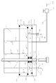
- Compressed air production equipment pressure air (fluid pressurization) circuit diagram Schematic diagram of seal mold with ejector box Schematic diagram of seal mold without ejector box Schematic diagram of outer cylinder 69 of pressure pin 50
- Schematic diagram of inner core 71 of pressure pin 50 Schematic diagram of pressure pin 50
- Schematic view of inner core 71 viewed from above Schematic view of pressure pin 50 viewed from below
- Schematic diagram of set screw Schematic showing the positional relationship between the pressure pin 50 and the cavity 200
- Schematic showing the positional relationship between the pressure pin 50 and the cavity 200
- Schematic diagram of outer cylinder 132 of pressure pin 204 Schematic diagram of inner core 133 of pressure pin 204
- Schematic diagram of pressure pin 204 Schematic diagram showing the circuit of pressurized fluid to the die of the pressurized pin Schematic diagram explaining the means for sealing each ejector pin in FIG.
- FIG. 36 is a perspective view of the fixed side of FIG. Schematic diagram of the molded product, in which pressurized fluid was introduced from the ejector pin and the action and effect were confirmed.
- 39 is a perspective view of the movable side of FIG. 39 is a perspective view of the fixed side of FIG.
- Schematic diagram of a molded product with gas ribs 218 around the ejector pin to prevent gas leakage from the ejector pin 42 is a perspective view of the movable side of FIG. 42 is a fixed perspective view of FIG. Cross-sectional view of FIG.
- Pneumatic circuit diagram of pressurized fluid manufacturing equipment with multiple pressurized circuits Schematic diagram of the mold with the seal plate extended beyond the mold Schematic diagram of machining the shape of the outer cylinder 132 directly into the nest Schematic diagram showing the circuit of the pressurized fluid in the seal plate by processing directly into the shape nest of the outer cylinder 132, inserting the inner core In FIG. 49, the seal plate.
- Schematic showing that multiple pressurized fluid circuits were installed on one sheet 49 is a schematic diagram showing that a plurality of seal plates are used and a circuit for pressurized fluid is installed in each of them.
- Schematic diagram of the outer cylinder 224 of the ejector pin 226 that pressurizes fluid from the ejector pin Schematic diagram of the inner core 225 of the ejector pin 226 that pressurizes fluid from the ejector pin
- Schematic diagram of ejector pin 226 that pressurizes fluid from ejector pin Schematic showing the means of fluid pressurization from the ejector pin
- Schematic diagram of ejector plate 28 showing means for pressurizing fluid from ejector pins
- Schematic diagram of ejector plate 29 showing means for pressurizing fluid from ejector pins 55 is a schematic diagram showing that a plurality of pressurized fluid circuits are installed on one ejector plate.
- 55 is a schematic diagram showing that a plurality of ejector plates are used and a circuit for pressurized fluid is installed in each of them.
- the present invention relates to an injection molding process of a resin (for example, a thermoplastic resin). More specifically, the present invention relates to a mold apparatus, an injection molding system, and a method for manufacturing a molded article that pressurize a resin by applying a pressurized fluid to the resin filled in a cavity.
- the resin may be a thermoplastic resin, rubber, or thermoplastic elastomer.
- injection / Pneumatic Molding means filling (injecting) a resin into a cavity, and during the injection, immediately after completion of injection, or after a predetermined time has elapsed after completion of injection, the resin filled in the cavity and the cavity surface
- An injection molding method in which a pressurized fluid is injected into the gap and the pressure of the pressurized fluid is applied to the resin in the cavity is also simply referred to as “pressure molding”.
- Injection-pneumatic molding is movable when only fluid pressurization is applied to the resin filled in the cavity with a short shot by the injection molding machine without using the resin holding pressure using the screw of the injection molding machine.
- the clamping force of the mold on the side and the mold on the fixed side can be lowered.
- injection pressure molding can process a large molded product with a small injection molding machine, and thus can reduce the processing cost of the molded product.
- injection pressure air molding does not use resin holding pressure, so there is little generation of parting burrs, especially burrs around the gate. Further, in the injection / pneumatic molding, the resin in the cavity is pressed (pressed) against the surface of the cavity with the pressure of the pressurized fluid, so that the transferability to the cavity is improved and the occurrence of sink marks can be suppressed.
- Molding space refers to a space filled with resin in a mold, and is synonymous with “cavity”. “Inside the cavity” refers to the interior, space, or volume of the cavity.
- injection refers to filling a cavity with resin, filling the cavity with resin, or a process thereof.
- Filling refers to placing resin in the cavity during injection molding.
- overshot Filling a volume of resin larger than the volume in the cavity is called overshot or overpack.
- volume refers to the volume (vol), weight (wt) or mass measured with a device such as a syringe or scale. Since the acceleration of gravity on the earth is substantially constant 9.8 Newton (N), weight and mass are synonymous.
- Parting refers to a joint portion between a fixed mold and a movable mold. A molding space is formed between the fixed mold and the movable mold, which are combined by parting, and the molding space is filled with resin.
- the fixed mold is an example of the first mold.
- the movable mold is an example of a second mold.
- the fixed mold may be referred to as a fixed mold or a fixed mold.
- the movable mold may be referred to as a movable mold or a movable mold.
- fixed mold parting portion (surface defining the molding space) where the resin filled in the cavity and the fixed mold are in contact.
- movable mold parting The part (surface that defines the molding space) where the resin filled in the cavity and the movable mold come into contact is called “movable mold parting” or “movable side parting”.
- the part where the slide core provided in the fixed mold is in contact with the resin filled in the fixed mold is called “fixed slide core parting”.
- movable slide core parting The part where the slide core provided in the movable mold contacts the resin filled in the movable mold is called “movable slide core parting”.
- the portion of the mold apparatus on which the pressurized fluid acts is the fixed-side mold pressurizing unit 111, the fixed-side mold slide core pressurizing unit 113, and the movable side
- the pressing part 110 of the metal mold or the pressing part 112 of the slide core of the movable mold is the fixed-side mold pressurizing unit 111, the fixed-side mold slide core pressurizing unit 113, and the movable side.
- Pressurized fluid refers to a gas or liquid compressed to atmospheric pressure ⁇ 760 mm (millimeters) Hg ⁇ or more. Supercritical things are included in the gas.
- carbonated water in which a gas is dissolved, microbubble water containing a gas, and the like are liquids.
- fluid refers to gas or liquid.
- Gas “Gas” is a fluid together with a liquid, the thermal motion of molecules exceeds the intermolecular force, and the molecules can move freely compared to the liquid state.
- the volume of gas varies greatly with pressure and temperature.
- gas does not have a constant volume, fills it when placed in a container, is rich in fluidity, and has the property of always spreading itself.
- the density of the gas is smaller than that of solid and liquid, and can be easily compressed.
- the volume of gas is proportional to temperature and inversely proportional to pressure.
- Vapor refers to a state in which a substance is vaporized from a liquid or sublimated from a solid into a gas.
- gases phase substances below the critical temperature are referred to as the gas phase.
- Vaporization refers to a phenomenon in which a substance changes from a liquid or solid to a gas. Evaporation includes evaporation and boiling.
- Liquid is a state in which molecules are attracting each other, but it is fluid, changes shape according to the container, and exhibits fluid properties similar to gas, but is less compressible than gas. So follow Pascal's principle. The liquid maintains a substantially constant density and, unlike gas, does not spread throughout the container. Liquids have surface tension as a unique property such as forming their own surface. Intuitively, “solid” if the shape is constant, “liquid” if the shape is not constant but the volume is constant, and “gas” is that the shape and volume are not constant.
- Fluid pressurization refers to putting pressurized fluid into the gap between the resin in the cavity and the cavity surface, applying pressure of the pressurized fluid to the resin, and applying (transmitting) pressure to the resin surface.
- fluid pressurization may be referred to as “pressurization by fluid”, “holding pressure by fluid”, or “fluid holding pressure”.
- pressing applying external pressure to a fluid is called “compression”.
- Resin holding pressure refers to, for example, applying pressure from the screw of an injection molding machine to the molten resin filled in the cavity to increase the density of the molten resin, improve transferability to the mold, and improve the appearance. This refers to reducing the occurrence of sink marks.
- Pressurized fluid is put into the gap between the resin injected into the cavity and the cavity surface of the first mold or the second mold (an example of the surface that defines the molding space) (the gap between the molten resin and the mold).
- the pressurized fluid leaks to the outside through the gap between the ejector pins, so that the pressurizing effect by the pressurized fluid is reduced.
- the ejector pin is an example of a shaft body.
- an ejector pin is provided with a seal (sealing member) such as an O-ring or a rubber sheet to prevent pressurized fluid from leaking outside the mold apparatus.
- a seal sealing member
- the sealed mold apparatus is called a seal mold.
- a mold apparatus without a seal has a drawback that a part of the pressurized fluid leaks to the outside.
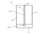
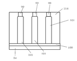
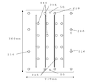
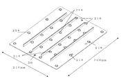
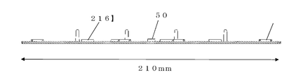
- the molded product is provided with ribs 211 as in the molded product 210 shown in FIG. 32 so that gas as an example of pressurized fluid applied to the gap between the resin in the cavity and the cavity does not leak to the outside. You can also.
- the rib 211 is referred to as a “gas rib” or a “pressurized rib”, and may be referred to as a “pressurized fluid leakage preventing rib”.
- Partial pressurization may provide similar gas ribs near the edges of the entire molded article to prevent pressurized fluid from leaking out.
- the parting seals such as the seal 40, the seal 41, and the seal 42 in FIG. 2 or the gas ribs are not necessarily used. .
- FIG. 1 is a pneumatic (pneumatic) circuit diagram of a pressurized fluid production apparatus 140 that produces pressurized fluid.
- Pressurized fluid manufacturing apparatus 140 can be changed by changing the interface with an injection molding machine (an example of a molding apparatus), etc., gas assist molding apparatus, inner gas counter pressure (IGCP) apparatus, MuCell, AMOTEC apparatus, etc. Can also be diverted to.
- IGCP inner gas counter pressure
- MuCell a method of performing injection / pressure forming using the pressurized fluid manufacturing apparatus 140 will be described.
- the nitrogen gas cylinder 1 is filled with nitrogen gas (an example of fluid) with a pressure of 15 MPa (megapascal).
- the nitrogen gas filled in the nitrogen gas cylinder 1 is once depressurized to about 1 MPa to 3 MPa by a regulator (pressure regulating valve) 4, and is compressed to about 30 MPa to 50 MPa using the gas booster 8, for example.
- the compressed high-pressure nitrogen gas (an example of a pressurized fluid) is accumulated in the receiver tank 10.
- the pressure may be reduced by a regulator (pressure adjusting valve) 12 that is set (adjusted) to an optimum pressure.
- the nitrogen gas may be nitrogen gas obtained by separation from the air using PSA or a separation membrane.
- PSA is a pressure swing adsorption method, which is a method of separating nitrogen gas from air by adsorption of activated carbon.
- the gas booster 8 may be a high pressure compressor.
- the pressurized fluid manufacturing apparatus 140 includes a pressure gauge 2 that indicates the pressure in the nitrogen gas cylinder 1, a manual valve 3 that is closed when the nitrogen gas cylinder 1 is replaced, a pressure gauge 5 that confirms the pressure set in the regulator 4, and a reverse flow of nitrogen gas.
- Check valve 6 for preventing pressure, pressure gauge 7 for confirming the pressure during compression of the intermediate stage of the gas booster 8, pressure gauge 9 for confirming the pressure in the receiver tank 10, and high-pressure nitrogen gas in the receiver tank 10 are removed.
- a manual valve (drain valve) 11, a pressure gauge 13 for confirming the pressure of the pressurized fluid, and a pipe 17 are provided.
- Reference numeral (arrow) 16 indicates the flow direction of the pressurized fluid
- reference numeral (arrow) 18 indicates the direction of the exhaust (blowout) of the pressurized fluid
- Reference numeral 20 denotes a pressurized fluid released into the atmosphere.
- the safety valve is installed at a necessary place such as the receiver tank 10.
- the pressurized fluid manufacturing apparatus 140 shown in FIG. 1 has one regulator 12 and one system of pressurized circuit. For this reason, the pressurized fluid manufacturing apparatus 140 can set one condition such as a pressurized pressure and a pressurized time.
- the pressurized fluid manufacturing apparatus 1140 shown in FIG. 46 has two systems for injecting into the mold 21 after the regulator 12 in FIG. For this reason, the pressurized fluid manufacturing apparatus 1140 can set the conditions such as the pressurizing pressure and pressurizing time of the fluid pressurization separately, or the injection pressure condition is initially high, then low, or vice versa. .
- the pressurized fluid manufacturing apparatus 1140 can set the optimum pressurizing conditions for each molded product in the case of pairing, two pieces, and many pieces. Having a plurality of pressurization circuits in this way makes it possible to set delicate fluid pressurization conditions.
- the timing (time, time) of fluid pressurization in injection / pneumatic molding includes, for example, the following modes. ⁇ Pressurization of fluid during resin filling into the cavity (Mode 1) -Immediately after filling the resin (immediately after) fluid pressurization (mode 2) ⁇ Fluid pressurization after a certain period of time after resin filling (Mode 3) ⁇ In order to reduce the pressure of the resin filled in the cavity, the screw of the injection molding machine is sucked back to a predetermined position immediately after filling the resin, and fluid pressurization immediately after the suck back is started (mode 4) -Fluid pressurization during mode of suck back (when a predetermined time or screw position has passed) (mode 5) -Fluid pressurization immediately after completion of suckback (mode 6) -Fluid pressurization after suck back is completed and a predetermined time has elapsed (mode 7)
- the transferability to the mold can be further improved.
- the cavity may be filled with resin while the fluid is pressurized while filling the cavity with resin or the like, and the resin may be further pressurized.
- the cavity may be filled with resin, resin holding pressure may be applied, and then sucked back.
- after filling the cavity with a full pack of resin apply resin pressure, and simultaneously with resin pressure, during resin pressure, immediately after completion of resin pressure, or after the time when resin pressure is completed Then, fluid pressurization may be performed.
- the pressurized fluid is supplied from one or more places in at least one of the movable side parting and the movable side slide core parting, or at least one of the fixed side parting and the fixed side slide core parting. Inject and fluid pressurize the resin in the cavity.
- the fluid pressurization in the injection-pneumatic molding includes direct pressurization and indirect pressurization.
- Direct pressurization is a method in which a pressurized fluid is directly put into a gap between a resin in a cavity and a cavity surface (fixed side parting or movable side parting). In the direct pressurization, the pressurized fluid is directly applied to the surface of the resin in the cavity from the inlet provided at the tip of the pressure pin, and the resin in the cavity is pressed against the cavity surface.
- “Indirect pressurization” is a method in which a pressurizing pin for a pressurizing fluid is provided in a place other than the cavity, and at least one of a movable side parting and a movable side slide core parting through a flow path of the pressurizing fluid, Or it is the method of pressurizing a part or all of resin which contacts at least one of fixed side parting and fixed side slide core parting.
- Pressurized fluid may be introduced from the bottom of the insert and allowed to act on the resin in the cavity from the ejector pin, the gap between the inserts, and the like.
- Indirect pressurization includes the seal 55 in FIG. 18 and the seal 93 in FIG. 19 to enclose all of the nesting and ejector pins 27 and the like, so that the entire nesting and ejector pins 27 are pressurized.
- sealing is performed separately for each block such as the seal 55 and the seal 93.
- “Holding time” refers to the time until the pressurization time ends and the release time to the atmosphere. During this time, both the valve 14 and the valve 15 are closed. The holding time has the effect of reducing the distortion inside the molded product.
- Air release time “Atmospheric release” refers to the time for exhausting the fluid in which the resin in the cavity is pressurized to the outside. The delay time, pressurization time, holding time, and atmospheric release time are opened and closed by a timer that can be arbitrarily set (pressurized pressure).
- Pressure pressure refers to the pressure of a fluid that pressurizes molten resin filled in a cavity. When the pressure applied by the regulator 12 is low, the transferability is lowered, but the distortion of the molded product is also reduced.
- the pressure pin may be one or more. Further, one or more injection ports may be formed at the tip of the pressure pin.
- the pressure of the pressurized fluid injected from each inlet may be equal or different.
- the injection time of the pressurized fluid injected from each injection port can also be set arbitrarily.
- the “injection port” refers to the tip of the pressurizing pin 50 from which the pressurized fluid is ejected.
- the pressurized fluid manufacturing apparatus 140 When the filling of the resin into the cavity 21 is started and the pressurized fluid manufacturing apparatus 140 receives a fluid pressurization start signal for the resin in the cavity 21 from the injection molding machine, the pressurized fluid manufacturing apparatus 140 opens the injection valve 14 in FIG. Pressurized fluid is injected into the movable parting or the like, and fluid pressurization of the resin in the cavity 21 is started.
- the pressurized fluid manufacturing apparatus 140 closes the injection valve 14 when the timer (not shown) is up (after the set time is over), and then opens the atmospheric discharge valve 15, for example. Then, the pressurized fluid in the cavity 21 is released ⁇ exhausted (blowed out) ⁇ into the atmosphere.
- the pressurized fluid manufacturing apparatus 140 does not need to open the atmospheric release valve 15. After the pressurized fluid is confined in the cavity 21 for a while, the atmospheric release valve 15 is opened and the cavity is released. The pressurized fluid in 21 may be released to the atmosphere. In the present invention, this case is referred to as “retention of pressurized fluid”, and the time during which the pressurized fluid is retained is referred to as “retention time”.
- a program (sequencer) stored in a control unit (not shown) of the pressurized fluid manufacturing apparatus 140 is reset in response to a signal from the injection molding machine, for example, a mold opening completion signal (completes the operation). .
- the pressurized fluid manufacturing apparatus 140 opens the injection valve 14 after accumulating (accumulating) the pressurized fluid of the pressure required for fluid pressurization in the receiver tank 10 regardless of the presence of the pressure regulating valve 12, and opens the receiver
- the resin in the cavity 21 may be fluidly pressurized with the pressurized fluid in the tank 10. This is called “pressure control (pressure control pressurization)” of the pressurized fluid.
- the pressurized fluid manufacturing apparatus 140 may eliminate the receiver tank 10 by changing the gas booster 8 to a plunger.
- the plunger also functions as the receiver tank 10 and measures the amount of fluid necessary for fluid pressurization each time (every shot, every time the molded product is manufactured) and pressurizes the fluid. This is called “volume control (volume control pressurization)” of the pressurized fluid.
- the plunger refers to a device having a cylinder and a piston as main components and the piston reciprocating with respect to the cylinder. That is, the plunger operates the piston in one direction to inject a predetermined volume of fluid into the cylinder, and then operates the piston in a direction opposite to the one direction to pressurize the fluid in the cylinder. Inject into the cavity.
- reference numeral (arrow) 19 indicates the flow direction of the pressurized fluid when the manual valve 11 is opened and the pressurized fluid in the receiver tank 10 is released into the atmosphere.
- the gas may be air, nitrogen, carbon dioxide (carbon dioxide), rare gas such as hydrogen, helium, argon, heated steam, oxygen, alcohol vapor, ether vapor, natural gas, or these It is a mixture of Usually, from the viewpoint of convenience such as unit price and safety, the fluid uses a gas mainly composed of nitrogen or air.
- the liquid usually uses water, but ether, alcohol, liquefied carbon dioxide, etc. can also be used.
- a low-temperature liquid for fluid pressurization if the resin filled in the cavity is a thermoplastic resin or a thermoplastic elastomer, the molten resin can be cooled and solidified faster, increasing the molding cycle, Productivity can be improved.
- a vaporizable liquid for example, liquefied carbon dioxide, ether, alcohol, or the like
- the liquid is vaporized by the heat of the molten resin (especially thermoplastic resin or thermoplastic elastomer). That is, since the liquid takes heat of the molten resin by the heat of vaporization, the solidification of the molten resin is accelerated and the molding cycle can be increased.
- the means of using the heat of vaporization is not limited to the fluid pressurization of injection-pneumatic molding, and can be carried out by hollow molding.
- the molding cycle can be expected to be increased by the heat of vaporization.
- Alcohol, ether, and the like injected into the cavity are released into the atmosphere or collected every cycle.
- the recovery means recovers the gas and liquid in the mold and the piping by suction, etc., cools, and compresses the liquid as necessary to make it liquid.
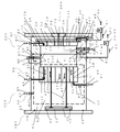
- the seal mold 141 has a box structure surrounding the ejector mechanism.
- the ejector mechanism refers to the ejector pin 27 and the ejector plate.
- the ejector plate includes an upper ejector plate 28 and an ejector plate lower 29.
- the ejector plate passes the ejector pin 27 through the through hole formed in the ejector plate 28, and the flange portion provided at the base end portion of the ejector pin 27 is connected to the ejector plate upper 28 and the ejector.
- the ejector pin 27 is fixed by being sandwiched between the lower plate 29.
- the mounting plate 23 on the movable side is formed with a through hole in a part of a portion facing the lower ejector plate 29.
- This through hole is a hole into which an ejector lot (not shown) connected to a mold clamping cylinder and a platen of an injection molding machine is inserted.
- the ejector lot reciprocates by, for example, reciprocation of an actuator such as a cylinder or a motor.
- the ejector pin reciprocates as the actuator and ejector plate reciprocate.
- the sealing mold 141 injects the pressurized fluid not only into the cavity 200 composed of the fixed-side cavity 30 and the movable-side cavity 31 but also into the space 52 created by the ejector box 51. Then, the seal mold 141 can cause the pressurized fluid to act on the surface of the resin in the cavity 200 from the gap along the ejector pin 27 as an example of the shaft body.
- the gap along the ejector pin 27 refers to a gap between the ejector pin 27 and the through hole through which the ejector pin 27 formed in the insert 34 constituting a part of the movable mold 202 is passed.
- the ejector box 51 is a structure (box structure) for confining and sealing the ejector mechanism in a closed space, and is indicated by a broken line in FIG.
- the seal mold 141 includes a fixed mold 201 and a movable mold 202.
- the seal mold 141 is an example of a mold apparatus.
- the fixed-side mold 201 is an example of a first mold.
- the movable mold 202 is an example of a second mold.
- the movable mold 202 can be brought into contact with and separated from the fixed mold 201 with the parting 26 as a boundary surface.
- the fixed-side mold 201 includes a fixed-side mounting plate 22 for mounting the fixed-side mold 201 to an injection molding machine (not shown), and a fixed-side mold plate 78 mounted on the fixed-side mounting plate 22.
- a spool bush 24 having a through-hole through which molten resin flows is attached to the fixed-side mounting plate 22, which is hit by a nozzle of an injection molding machine.
- the template 78 includes a fixed-side cavity 30, a spool 25 that guides the molten resin flowing from the spool bush 24 to the fixed-side cavity 30, a fixed-side insert 32, and a slide core 36. ing.
- the movable mold 202 includes a movable attachment plate 23 for attaching the movable mold 202 to an injection molding machine (not shown), and a movable mold plate 87 attached to the movable attachment plate 23.
- the mold plate 87 has an ejector pin 27 for extruding a molded product from the cavity, an ejector pin 27 fixed to the ejector pin 27, an ejector plate upper 28 and an ejector plate lower 29, a movable side cavity 31, and a movable side entrance.
- the seal mold 141 is provided with various seals in order to prevent the pressurized fluid from leaking outside the seal mold 141. That is, the seal mold 141 includes a seal 38 provided for the purpose of preventing leakage of pressurized fluid from the spool bush 24, a seal 39 between the fixed side mounting plate 22 and the fixed side mold plate 78, and a movable side.
- symbol (arrow) 47 shows the flow direction of a pressurized fluid.
- reference numeral 47 in the fixed side mold 201 is the same as that in the movable side mold 202, the illustration is omitted.
- Reference numeral 33 denotes a gap between the fixed side nests
- reference numeral 35 denotes a gap between the movable side nests.
- the pressure pin 50 is shown in detail in FIGS. 4 to 17 and the structure for mounting in the mold.
- the sealing mold 141 further injects the pressurized fluid directly into the resin in the cavity 200 by injecting the pressurized fluid into the space 52 created by the ejector box 51, and fixes the resin in the cavity 200.
- Injection means 57 that directly pressurizes fluid from the side
- injection means 58 that injects pressurized fluid directly into the resin in the cavity 200 and fluid pressurizes the resin in the cavity 200 directly from the movable side (on the upper side of the drawing in FIG. 2).
- an injecting means 60 for injecting pressurized fluid directly into the resin therein and fluid pressurizing the resin in the cavity 200.
- the resin in the cavity 200 can be indirectly fluid-pressurized.
- the injection means 61 injects pressurized fluid into the gap between the seal plate lower 44 and the seal plate upper 45, and fluidly pressurizes the resin in the cavity 200 from the fixed side through the gap of the insert 32.
- FIG. 3 illustrates that the plate 53 and the plate 54 are provided at the bottom of the insert.
- the plate 53 and the plate 54 are sandwiched and fixed between the block of the ejector and the movable side plate.
- Such means can also be implemented on the fixed side, slide core.
- the fluid pressurization from the ejector pin shown in FIG. 52 to FIG. 60 can suppress the disturbance of the shape of the molded product described above because the pressurized fluid comes out only from the tip of the ejector pin. Further, fluid pressurization in which a pressurized fluid is discharged only from an ejector pin can cope with a complicated shape of a molded product.
- the outer cylinder 224 of the ejector pin shown in FIG. 52 includes a hollow shaft portion in which a through hole 77 into which the inner core 225 is inserted, and a flange portion 70 formed at one end of the shaft portion. ,have.
- the flange portion 70 is formed with a recess 79 that communicates with the through hole 77 so that the flange portion 117 of the inner core 225 can be inserted.
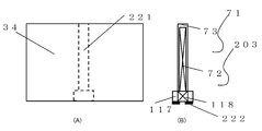
- FIG. 53 is a schematic diagram of the core body part 226. Similarly to FIG.
- the core body portion 226 includes a shaft portion and a flange portion 117 formed at one end of the shaft portion.
- a D-cut portion 72 is formed on the shaft portion, and a D-cut portion 118 is formed on the collar portion 117.
- the pressurized fluid passes through these D-cut portions 118 and 72.
- the tip 73 is processed in the same shape as 74 and 75 in FIG.
- the groove 117 is subjected to the groove processing of FIGS. 7 and 8.
- FIG. 54 is a view showing an ejector pin 227 having a structure of a pressure pin in which a core portion 226 is inserted into the outer cylinder 223.
- the pressurized fluid introduced from the base end portion of the ejector pin 227 passes through the gap between the through hole 77 and the D cut portion 118 and exits from the tip end portion 119.
- FIG. 55 is a schematic diagram showing a mold structure in which the ejector pins 227 are incorporated into a mold.
- reference numeral 34 denotes a nest
- reference numeral 35 denotes a nest gap.
- the configurations of the seal 93, the plate 53, the plate 54, the seal 55, and the seal 89 of the ejector pin 227 for preventing leakage of pressurized fluid from the nest gap 35 are the same as those in FIG. That is, the flange portion 70 of the ejector pin 227 is sandwiched between the plate 28 and the plate 29.
- a seal 228 is provided between the upper surface of the flange 70 and the plate 28 so that the pressurized fluid does not leak out.
- a seal 229 is provided between the plate 28 and the plate 29 to prevent the pressurized fluid from leaking between the plate 28 and the plate 29. If necessary, the bottom surface of the plate 29 and the surface where the mounting plate 23 contacts are also sealed with 230.
- Reference numeral 49 denotes a passage for the pressurized fluid
- reference numeral 48 denotes a connection port between the pressurized fluid manufacturing apparatus 140 shown in FIG. 1 and the pressurized fluid manufacturing apparatus 1140 shown in FIG.
- the plate 28 shown in FIG. 56 is a view of the plate 28 of FIG. 55 as viewed from above the paper, and is formed with a recess 231 and a recess 232 in which the flange 70 of the ejector pin 227 is accommodated.
- the plate 29 shown in FIG. 57 is a view of the plate 29 of FIG. 55 as viewed from above the paper surface.
- the plate 29 is formed with a groove 236 through which the pressurized fluid passes and a passage (through hole) 49.
- the passage 49 is configured such that one end communicates with the groove 236 and the other end is connectable to the connection port 48.
- the groove 236 forms a flow path (pneumatic circuit) through which the pressurized fluid passes by combining the plate 28 and the plate 29. Further, the groove 236 is formed at a position where the groove 236 communicates (connects) with the recess 231 and the recess 232 when the plate 28 and the plate 29 are combined.
- FIG. 58 (A) shows another embodiment of attaching the ejector pin 227 in the mold structure shown in FIG. That is, the seal 93, the plate 53, the plate 54, the seal 55, the insert 34, and the like are not shown in FIG. 58A for easy understanding.
- FIG. 58B is a view of the plate 28 of FIG. 58A as viewed from above the paper surface of FIG. 58A.
- FIG. 58 (C) is a view of the plate 28 of FIG. 58 (A) as viewed from above in FIG. 58 (A).
- the plate 28 has a through hole 233 and a through hole 234 formed therein.
- a recess (a counterbore portion) in which the flange 70 of the ejector pin 227 is located is formed in each of the through hole 233 and the through hole 234.
- the plate 29 is formed with grooves 237 and 238 through which the pressurized fluid passes, and two passages (through holes) 49.
- Each passage 49 is configured such that one end communicates with a groove (groove 237 or groove 238) and the other end can be connected to the connection port 48.
- the groove 237 and the groove 238 form an air pressure circuit through which the pressurized fluid passes by combining the plate 28 and the plate 29.
- the groove 237 and the groove 238 are formed at a position where they communicate (connect) with the through hole 231 and the through hole 232 when the plate 28 and the plate 29 are combined.
- the groove 237 and the groove 238 are formed at positions that communicate with the two concave portions into which the flange portions 70 of the ejector pins 227 are inserted when the plate 28 and the plate 29 are combined.
- FIG. 59 (A) shows another embodiment of attaching the ejector pin 227 in the mold structure shown in FIG.
- FIG. 59B is a view of the upper plate 29 in FIG. 59A as viewed from above in FIG. 59A.
- FIG. 59C is a view of the lower plate 29 in FIG. 59A as viewed from above in FIG. 58A.
- FIG. 59D is a view of the upper plate 28 in FIG. 59A as viewed from above in FIG. 59A.
- FIG. 59E is a view of the lower plate 29 of FIG. 59A as viewed from the upper side of FIG. 58A.
- FIGS. 59B is a view of the upper plate 29 in FIG. 59A as viewed from above in FIG. 59A.
- FIG. 59C is a view of the lower plate 29 in FIG. 59A as viewed from above in FIG. 58A.
- FIG. 59D is a view of the upper plate 28 in FIG. 59A as viewed from above in FIG. 59A.
- FIG. 59E is a view of the lower plate
- the attachment structure of the ejector pin 227 shown in FIG. 59A uses a plurality of a pair of plates including a plate 28 and a plate 29 that sandwich the flange portion 70 of the ejector pin 227. In other words, the attachment structure is to erect the ejector pin 227 from each pair of plates.
- Each pair of plates is formed with a groove and a passage through which the pressurized fluid passes. For this reason, the pressurized fluid manufactured by the pressurized fluid manufacturing apparatus 1140 shown in FIG. 46 can be molded into a molded product under different fluid pressurizing conditions by supplying the pressurized fluid to each pair of plates.
- FIG. 55 and the like show a means for providing a connection port 48 in the plate 29 and guiding the pressurized fluid to the ejector pin 227.
- FIG. 60 shows the means for supplying pressurized fluid from the mounting plate 23 to the plates 28 and 29.
- a connecting port 48 is provided in the mounting plate 23, a passage 49 is processed therein, and is connected to the bottom surface of the concave shape 242.
- the plate 28 has a convex shape 241 combined with the concave portion 232, and a passage 49 is processed in the convex shape 241.
- the passage 49 of the plate 28 the groove 236, the groove 237, the groove 238, the groove 239, the groove 240.
- FIG. 60 shows the case where the plate 28 is provided.
- the valve 62 is a valve for releasing air in the cavity 200 from the parting 26 to the outside of the seal mold 141 when the resin is filled in the cavity 200 to prevent short molding, discoloration, and burning. .
- the valve 62 is opened until the resin is filled into the cavity 200 (resin filling is completed), and the air in the cavity 200 pushed away by the resin filling is exhausted to the outside from the valve 62.
- the FIG. 23 shows a detailed mold parting structure of the air exhaust means.
- the air in the cavity 200 is exhausted from a gas vent (not shown) provided in the parting 26 through a passage 63 in a seal mold 141 provided for exhaust.
- Reference numeral 64 is a pressure-resistant hose having a high-pressure specification connected to a valve 62 provided for exhausting air in the cavity 200.
- Reference numeral (arrow) 65 indicates the flow of air exhaust in the cavity 200.
- Reference numeral 66 denotes air in the cavity released into the atmosphere.
- valve 67 having the same action as the valve 62 is provided.
- valve 62 The functions of the valve 62, the valve 67, and the valve 68 can be provided to the automatic opening / closing valve 15 shown in FIG.
- the valve 62, valve 67, and valve 68 of FIG. 3 are eliminated, and the hose 64 is connected to the automatic opening / closing valve 15.
- the valve 15 While the resin is filled in the cavity, the valve 15 is opened, and the air in the cavity pushed out by the filling is exhausted.
- the valve is closed and the valve 14 is opened to pressurize the fluid. This can be carried out without using the exhaust valve 62 in the mold.
- the above description is the valve 62.
- the valve 15 and the function of the valve 68 have been explained to be given to the valve 15, even if the number of the valves 15 is not one and only three corresponding to the valves 62, 67 and 68 are used, more than that. Also good.
- seal mold 141 other configurations provided in the seal mold 141, such as a mold receiving plate, a support pillar, an ejector return pin and return spring, a guide pin and a guide post, are not shown in FIG.
- the fluid used in the seal mold 141 is preferably a gas rather than a liquid.
- the seal mold 141 provided with the ejector box 51 does not need a plate 53, a plate 54, and a seal 55 in FIG.
- the seal mold 141 is characterized in that the fixed mold 201 and the movable mold 202 are clamped, and the cavity 200 is closed when the nozzle of the injection molding machine comes into contact with the spool bush 24. (Seal mold) ”. For this reason, the seals 38 to 43 are used.
- Direct pressurization is a method in which a pressurization fluid is applied to the resin in the cavity 200 using the pressurization pin 50 to pressurize the fluid.
- direct pressurization a pressurized fluid is put into a place other than the inside of the cavity 200, and the pressurized fluid flows from the gap 35 of the movable side insert 34, the gap along the ejector pin 27, the gap of the core pin, and the like. This is a method of reaching the resin in the cavity 200 and fluidly pressurizing the resin in the cavity.
- a pressurized fluid is put into the bottom of the insert 34 and the insert 34 is moved to pressurize the insert.
- the injection means 58 shown in FIG. 2 is also used when the resin in the cavity 200 is directly pressurized.
- the injection means 58 includes a connection port 48, a pressurized fluid passage 49, and a pressure pin 50.
- the connection port 48 is a connection part for connecting one end part of the pressure hose through which the pressurized fluid flows.
- the other end of the pressure hose is connected to the pipe 17 of the pressurized fluid manufacturing apparatus shown in FIG. Specifically, the other end of the pressure hose is connected to the end of the pipe 17 in FIG.
- the passage 49 guides the pressurized fluid flowing from the pressure hose through the connection port 48 to the cavity 200, the space 52, and the like, and the mold 78 of the fixed mold 201 or the mold of the movable mold 202. It is a hole formed in the plate 87.
- the pressure pin has an injection port formed at the distal end portion and a through hole connecting the injection port and the proximal end portion. Since the proximal end portion of the pressure pin is connected to the passage 49, the pressurized fluid flowing from the passage 49 is injected into the cavity 200 from the inlet through the through hole of the pressure pin.
- the pressurized fluid that has flowed out of the injection port enters the gap between the resin in the cavity 200 and the cavity. Get in. That is, when pressurized fluid is injected into the movable cavity from the injection port provided in the movable mold 202, the resin is pressed in the direction from the movable mold 202 toward the fixed mold 201. Apply fluid pressure. In other words, the resin in the cavity 200 is pressed against the cavity 30 on the fixed side by the pressurized fluid.
- the seal 40 when the pressurized fluid pressurizes the resin in the cavity 200, the pressurized fluid leaks to the outside from the parting 26 which is the mating surface of the movable mold 202 and the fixed mold 201. It is provided to prevent this.
- the seal 40 include an O-ring and a plate-like rubber sheet (sealing member). The sealing member is provided on the entire surface or part of the parting 26.
- the seal mold 141 is sealed (sealed) by the seal 43 provided under the ejector plate 29 when the fixed mold 201 and the movable mold 202 are closed and the ejector pin 27 is retracted. For this reason, in the seal mold 141, the pressurized fluid leaks from the gap between the ejector lot (not shown) into which the ejector lot (not shown) formed in the movable mounting plate 23 is inserted. Can be prevented. That is, the seal mold 141 is provided with the seal 39 between the movable side mounting plate 23 and the ejector box 51, and is also provided with a seal (not shown) between the ejector box 51 and the movable side plate 87. Examples of the seal 43 include an O-ring and a plate-like rubber sheet (sealing member).
- the pressurized fluid acting on the surface of the resin in the cavity 200 passes through the gap along the ejector pin 27 and the gap of the nest 34, and enters the space 52 of the ejector box 51. Since the mating surfaces are sealed, they do not leak out of the sealing mold 141.
- the pressurized fluid When the pressurized fluid is injected into the cavity 200 only from the injection means 58 and the resin in the cavity 200 is fluid-pressurized, the pressurized fluid enters the space 52 of the ejector box 51 as described above. For this reason, when injection pressure air forming is performed using the seal mold 141, the pressure of the pressurized fluid in the space 52 of the ejector box 51 is equal to the pressure of the pressurized fluid that pressurizes the resin in the cavity 200. Otherwise, the action and effect of fluid pressurization is low.
- the pressurized fluid is injected into the cavity 200 from the injection unit 58 and also injected into the space 52 of the ejector box 51 from the injection unit 56. It is desirable to fill the space 52 with pressurized fluid. By doing so, the pressure of the pressurized fluid in the space 52 of the ejector box 51 can be made equal to the pressure of the pressurized fluid injected into the resin in the cavity 200 by the injection means 58 in a short time.
- the pressurized fluid injected into the space 52 and the pressurized fluid injected into the cavity 200 may be exhausted simultaneously using the injection means 56 and 58 or may be exhausted separately with a time difference.
- the injection means 56 and 58 are used for exhausting pressurized fluid, no pressurized fluid flows through the pressure hose connected to the injection means 56 and 58, and the pressure hose should be open to the atmosphere. Needless to say.
- the pressure hose connected to the end of the pipe 17 in FIG. 1 is in a state where the injection valve 14 is closed and the air release valve 15 is opened.
- the exhaust of the pressurized fluid injected into the space 52 and the cavity 200 may be exhausted using an exhaust means (not shown) dedicated to the movable mold 202 separately from the injection means 56 and 58.
- pressurization pins shown in FIGS. 4 to 17 are provided in places where pressurization is necessary as required.
- the tips of these pressure pins are in contact with the surface of the resin in the cavity.
- the rear end portions (base end portions) of these pressure pins are accommodated in the ejector box 51. Then, if the pressurized fluid is injected into the space 52 of the ejector box 51, the required place in the cavity 200 can be fluid-pressurized.
- a plurality of pressure pins may be provided.
- the pressurized fluid is not injected from the injection means 58, so that it is not necessary to provide the injection means 58 in the movable mold 202.
- the sealing die 141 having the ejector box 51 Since the sealing die 141 having the ejector box 51 is hermetically sealed, the air in the cavity that causes short molding, discoloration or burning when the resin is filled is filled with the gap 35 of the insert, the ejector pin 27. It moves in the space 52 from the gap along the line. For this reason, the seal mold 141 can suppress short molding, discoloration, and burning.
- the injection means 57 shown in FIGS. 2 and 3 In the case where pressure is applied directly from the fixed mold 201, the injection means 57 shown in FIGS. 2 and 3 is used. When indirect pressure is applied from the fixed mold 201, the injection means 61 shown in FIGS. 2 and 3 is used. When a pressurized fluid is injected from at least one of the injection means 57 and 61, the pressurized fluid fluidly pressurizes the resin in the cavity 200 in a direction from the fixed mold 201 to the movable mold 202. Since the injection means 57 and 61 have the same configuration as the connection port 48, the pressurized fluid passage 49, and the pressure pin 50 described in the injection means 58, detailed description will be omitted.
- the injection means 61 injects a pressurized fluid between the lower seal plate 44 and the upper seal plate 45. For this reason, the injected pressurized fluid enters the fixed cavity 30 through the nest gap 33 or the like, and the resin in the cavity 200 is fluidized in the direction from the fixed mold 201 to the movable mold 202. Press.
- the direct pressing of the movable mold 202 may be performed by providing the ejector box 51 with the rear end portion of the pressing pin.
- direct pressing of the fixed-side mold 201 applies pressure to the fixed-side mold 201 so that the rear end of the pressing pin is located between the lower seal plate 44 and the upper seal plate 45.
- a pin may be provided.
- the injection means 61 is a pressurized fluid injection means for putting a pressurized fluid between the lower seal plate 44 and the upper seal plate 45.
- the pressurized fluid injected using the injection means 61 reaches the fixed parting from the gap 33 of the nest 32 and moves the resin in the cavity 200 from the fixed mold 201 to the movable mold 202.
- Apply fluid pressure In particular, where fluid pressure is required, as in the case of the movable side described above, a pressure pin shown in FIGS. 4 to 17 is provided as necessary, and the gap between the seal plate lower 44 and the seal plate upper 45 is pressurized. Fluid pressurization can be achieved simply by adding fluid.
- the pressure pin 50 can be manufactured, for example, by additionally processing an ejector sleeve pin of MISUMI Corporation. Hereinafter, the pressure pin 50 will be described with reference to FIGS.
- the pressure pin 50 has an outer cylinder 69 and an inner core 71 inserted into the outer cylinder 69 as shown in FIG.
- the outer cylinder 69 includes a flange portion 70 formed at one end (base end portion) in the longitudinal direction, a recess 79 formed in the flange 70, and the other end in the longitudinal direction from the recess 79. And a through hole 77 connected to the portion (tip portion).
- the inner core 71 includes a columnar collar 117 formed at one end (base end) in the longitudinal direction, a columnar core body 203 connected to the collar 117, and a collar A D surface (D cut) 118 formed on 117, and a D surface (D cut) 72 formed on the core body portion 203 from the flange portion 117 to the distal end portion 73.
- D-planes 72 and 118 are formed for flowing pressurized fluid.
- tip part 73 of the inner core 71 the part in which the D surface 72 is not formed has about 5 mm.
- the pressure pin 50 is configured by inserting the core body portion 203 of the inner core 71 into the through hole 77 of the outer cylinder 69.
- the inner diameter of the through-hole 77 and the outer diameter of the core body portion 203 are such that a gap of about 0.01 to 0.1 mm through which pressurized fluid passes but resin does not pass at the tip of the pressurizing pin 50 is formed. Is set.
- the length of the inner core 71 (the length in the longitudinal direction of the inner core 71) is the length of the outer cylinder 69 (the longitudinal direction of the outer cylinder 69).
- the length is slightly shorter (greater than 0 mm and 0.5 mm or less).
- the length of the inner core 71 and the length of the outer cylinder 69 may be the same. Further, the pressurizing pin 50 may make the length of the inner core 71 longer than the length of the outer cylinder 69.
- the length of the inner core 71 and the length of the outer cylinder 69 are selectively used depending on the type of resin and the shape of the molded product.
- FIG. 7 is a view of the inner core 71 as viewed from above. In other words, FIG. 7 is a view of the inner core 71 shown in FIG. 5 rotated 90 degrees in the circumferential direction and viewed from the top to the bottom of the drawing.
- FIG. 8 is a view of the inner core 71 as viewed from below. In other words, FIG. 8 is a view of the inner core 71 shown in FIG. 5 rotated 90 degrees in the circumferential direction and viewed from the lower side to the upper side.
- FIG. 9 is a view of the distal end portion 73 of the core body portion 203 as viewed from above. In other words, FIG. 9 is a view of only the front end portion 73 of the core body portion 203 shown in FIG.
- a set screw 127 shown in FIG. 10 is used to fix the pressure pin 50 to the mold 201 on the fixed side.
- the set screw 127 includes a screw part 123 formed on the outer peripheral part, a concave part 122 having a polygonal cross section formed on one end part in the longitudinal direction, and a through hole 121 extending from the concave part 122 to the other end part in the longitudinal direction. Have.
- FIG. 12 and FIG. 13 show the position of the pressure pin 50 with respect to the molded product 124 molded by the cavity 200 (the molded product 124 in the cavity 200).
- the tip surface of the tip of the outer cylinder 71 of the pressure pin 50 is flush with the surface of the cavity 200 (equivalent), and the tip of the tip of the inner core 71 is slightly lowered from the tip of the outer cylinder 71.
- the fixed-side mold 201 or the movable-side mold 202 using this configuration can easily inject pressurized fluid into the gap between the resin in the cavity (molded product 124) and the cavity surface.
- FIG. 12 shows a configuration having a protruding portion 129 in which the cavity surface around the pressing pin 50 is protruded to the cavity side.
- the fixed-side mold 201 or the movable-side mold 202 having the above configuration has a thin portion at the protruding portion 129 when viewed from the molded product 124 side, so that cooling and solidification of the thin portion can be accelerated. Can do.
- the fixed-side mold 201 or the like using this configuration is likely to form a skin (solidified) layer in the thin portion facing the injection port of the pressurizing pin 50, so that the pressurized fluid is used as the resin in the cavity. It becomes easy to inject into the gap with the cavity surface.
- the pressurizing pin 50 in FIG. 36 is slightly decentered and subjected to rough texture processing (220 in FIG. 36) of ⁇ 20.
- FIG. 13 shows a configuration in which a recess 130 having a diameter slightly larger than the diameter of the inner core 71 of the pressure pin 50 is formed in the cavity 200 forming the molded product 124.
- the diameter of the recess 130 may be equal to the diameter of the inner core 71 of the pressure pin 50.
- a boss is formed in the molded product 124 by the recess 130.
- the pressure pin 50 is fixed by a set screw 127 so that the center axis of the pressure pin 50 and the center axis of the set screw substantially coincide. Then, the pressurized fluid passes through a through hole 121 formed at the center of the set screw 127 and the pressure pin 50 and is injected into the gap between the resin (molded product 124) in the cavity 200 and the surface constituting the cavity 200.
- the pressurizing pin 50 is provided with an O-ring 126 as a seal (sealing member) in order to prevent leakage of pressurized fluid. Since the O-ring 126 is a line contact, the sealing performance is poor. For this reason, it is desirable that the seal used for the pressure pin 50 is a rubber sheet processed into a donut shape. When a rubber sheet is used, surface contact is achieved, and therefore, sealing performance is higher than that of line contact. 11, 12, and 13, the configuration in which the O-ring 126 is provided on the upper surface of the flange portion 70 of the pressure pin 50 is shown. However, the seal may be provided on the lower surface or the side surface of the collar portion 70 as long as the sealability can be secured.
- the seal may be provided on a plurality of surfaces such as an upper surface and a lower surface of the flange portion 70.
- a plurality of surfaces of the flange portion 70 there is an advantage that high sealing performance can be obtained.
- the pressure of the pressurized fluid can be high near the gate and low at the flow end (position away from the gate).
- the position and the number of the pressure pins 50 are determined according to the shape of the molded product.
- a plurality of pressurizing pins 50 are provided in the vicinity of the gate and at the flow end, and a pressurizing fluid having an optimal pressure can be injected into each pressurizing pin 50 in an optimal time.
- the pressure pin 50 described with reference to FIGS. 4 to 13 has an injection port formed in a direction along the longitudinal direction of the pressure pin.
- the pressure pin 204 has an injection port formed in a direction crossing the direction along the longitudinal direction of the pressure pin.
- the pressurizing pin 204 has a structure in which the pressurized fluid exits from the side surface of the pressurizing pin 204.
- the pressure pin 204 has an outer cylinder 132 and an inner core 133 inserted into the outer cylinder 132.
- the outer cylinder 132 includes a flange portion 207 formed at one end portion (base end portion) in the longitudinal direction, and a through hole 80 connected from the flange portion 207 to the other end portion (leading end portion) in the longitudinal direction. And have.
- the inner core 133 includes a columnar flange 135 formed at one end (base end) in the longitudinal direction, a columnar core connected to the flange 135, and the core And a D surface (D cut) 134 formed from the flange 135 to the other end (tip).
- the D surface 134 is formed for flowing a pressurized fluid.
- the length (height) of the longitudinal direction of the collar part 135 is about 1 mm to 5 mm.
- FIG. 16 shows the position of the pressure pin 50 with respect to the molded product 124 molded by the cavity 200 (the molded product 124 in the cavity 200).
- a recess 136 is formed in the cavity 200. That is, a boss is formed on the molded product 124 by the recess 136.
- the diameter of the recess 136 is set to be smaller than the diameter of the flange 135 of the inner core 133.
- the flange portion 207 of the pressurizing pin 204 includes a seal (sealing member) 126 for preventing leakage of the pressurized fluid.
- the pressurized fluid passes through the through hole 80 of the outer cylinder 132 and the D surface 134 of the inner core 133, exits from the gap where the tip surface of the outer cylinder 132 and the flange 135 of the inner core 133 abut, and forms a recess 136.
- the resin in the cavity is fluidly pressurized through the space between the surface to be pressed and the resin (boss portion) injected into the recess.
- FIG. 49 is a diagram in which an inner core 71 is incorporated using FIG.
- the lower part of FIG. 49 is a schematic diagram (plan view) of the plate 53 of the upper part as viewed from the upper side to the lower side.
- the groove 81 and the passages 49 and 48 shown in the lower part of FIG. 49 are separated from each other, and the fluid pressurizing conditions are separately set using the pressurized fluid manufacturing apparatus 1140 shown in FIG. Enabled to set.
- channel 81 is set separately, naturally exhaust circuits, such as the valve 68, are also installed separately.
- FIG. 51 uses a plurality of plates 53 and 54 shown in FIG. 49, each of which forms a circuit for pressurized fluid, and uses the pressurized fluid manufacturing apparatus 1140 shown in FIG. The conditions can be set separately. As in the description of FIG. 50, an exhaust circuit such as a valve 68 is also provided separately. 49, 49, 50, and 51, the seals 55, 91, and 93 shown in FIGS. 19 and 20 and the like are used in the same manner, but are not shown in FIG. 49 and the like.
- FIG. 17 shows a state in which the pressure pin 50 or 204 shown in FIGS. 4 to 16 is provided in the fixed mold 201 or the movable mold 202.
- the pressurizing pin 50 or 204 is connected to a pressurized fluid circuit formed of a stainless steel tube 49 by using a high-pressure joint 76 connected to the flange 70 or 207.
- An example of the high-pressure joint 76 is a joint for high-pressure piping manufactured by Nippon Swagelok Co., Ltd.
- the pressure when filling the cavity with resin is called “filling pressure” or “injection pressure” and is expressed as a percentage (%) using MPa (megapascal), kg / cm 2 , or the ratio of the maximum injection pressure of the injection molding machine. ).
- the speed when filling the cavity with resin is called “filling speed” and “injection speed”, using the screw moving speed of the injection molding machine, mm / sec (seconds), or the maximum injection of the injection molding machine. Expressed as a percentage using the rate of speed.
- the volume or weight of the resin to be filled per time when the resin is filled in the cavity is referred to as “filling rate” and “injection rate”, ml (milliliter) / sec, cc / sec. It is expressed in cm 3 / sec or g (gram) / sec.
- ABS which is a thermoplastic resin.
- the pressure applied to the molten ABS in the heating cylinder is about 200 MPa at maximum, which is a high pressure.
- the pressure drops to about 30 MPa due to pressure loss (pressure loss).
- the pressure of about 30 MPa of ABS during the filling is not so high. The reason is that the cavity still has an unfilled space. In other words, the ABS in the cavity has not yet reached the flow end and is in a short mold state, so there is no pushing pressure from the cavity wall (in this case, reaction from the wall) when fully filled. Because.
- the ABS is cooled and solidified at the same time as the cavity is filled with ABS, and a skin layer is formed. That is, since ABS is solidified from a molten state, volume shrinkage occurs and a gap is generated between the cavity surface and the ABS surface.
- the pressure of the pressurized fluid is applied to the cavity surface and the ABS that has not been cooled and solidified yet. Since ABS is easier to compress than the cavity surface, it is pressurized and compressed by the pressure of the pressurized fluid. This is called the “wedge effect”. Due to the wedge effect, the resin in the cavity is pressurized as a whole, such as a movable side parting, a fixed side parting, a movable side slide core parting, or a range until reaching the fixed side slide core parting. When the gas rib is provided, the pressurized fluid spreads in the gas rib due to the wedge effect, and the resin in the cavity is partially pressurized. In order to fully exhibit the wedge effect, the pressure of the ABS filled in the cavity is preferably low. In this case, the pressure of the pressurized fluid can be lowered.
- ABS pressure of pressurized fluid
- ABS pressure of pressurized fluid
- a dummy shape or a discarded shape is provided at the end of the cavity except for sucking back the screw of the injection molding machine.
- the molten ABS exceeds the capacity of the cavity and fills the middle of the dummy shape to form a short mold, and the pressure of the ABS in the cavity is lowered.
- the dummy shape may be thick.
- the dummy shape may be provided with a shutter, the ABS is filled in the cavity with a full pack, the shutter is opened, and the ABS is pushed out into the dummy shape by fluid pressurization to reduce the pressure of the ABS in the cavity.
- means for exerting the wedge effect include applying a texture or coating to the cavity surface.
- a molded product having a large projected area can be processed by a molding machine having a low clamping force.
- the molded product has less internal distortion and less warpage and deformation.
- the thickness of the molded product that can be carried out in the present invention is not limited, but in the case of a thermoplastic resin, it is 1 mm or more and 5 mm or less, preferably about 1 mm to 4 mm.
- the fluid pressurization can be performed by a total pressurization applied to the entire molded article (for example, the entire movable side parting) and a partial pressurization applied partially.
- a pressurization pin is provided on a surface to be pressurized (fixed side parting or movable side parting) to pressurize the fluid.
- the number of pressure pins is determined by the pressure area and thickness of the molded product.
- Partial pressurization is an effective means for applying a pressurized fluid only to a portion where it is desired to reduce sink marks or to improve transferability.
- the pressurization pin 50 is installed in the cavity and pressurization is performed. It is only necessary to pressurize the fluid using the pin 50.
- the lower seal plate 53 below the insert 34 of the movable mold 202 and the upper seal plate 54 below the movable insert are used.
- the molded product 1 and the molded product 2 in the examples are molded products molded by overall pressure.
- the molded product 3 is a molded product molded by partial pressure.
- the molds 201 and 205 on the fixed side use the lower seal plate 44, the upper seal plate 45, and the seal 46, so that there is no escape space for air in the cavity 200 when the resin is filled into the cavity 200.
- the movable molds 202 and 206 use the lower seal plate 53, the upper seal plate 54, and the seal 55, thereby eliminating the escape space of the air in the cavity 200 when the resin is filled in the cavity 200. For this reason, the seal mold 142 using the fixed mold 201 and the movable mold 202 may cause short molding, discoloration, or burning.
- the sealing molds 141 and 142 are fluid discharging means (an example of a discharging unit) for extracting gas from the insert 32 in the fixed molds 201 and 205.
- a space is provided in the bottom (surface opposite to the cavity 200), and the air in the cavity is evacuated to the outside of the mold when the resin is filled.
- the sealing molds 141 and 142 are provided with a space on the bottom (surface opposite to the cavity 200) of the fluid discharge means for extracting gas from the insert 34 in the movable molds 202 and 206, and on the seal plate 54 (resin side). Devise to let the air in the cavity escape to the outside of the mold when filling with.
- the molds 201 and 205 on the fixed side provide a small space between the upper seal plate 44 and the lower seal plate 45 and the seal 46.
- the movable molds 202 and 206 provide a small space (for example, the space 102 in FIG. 19) between the upper seal plate 54 and the lower seal plate 53 and the seal 55.
- FIG. 18 shows the structure of the lower seal plate 53, the upper seal plate 54, and the seal 55 in FIG.
- the lower seal plate 53 and the upper seal plate 54 have holes 83 (FIG. 19) through which the ejector pins 27 are inserted (sliding) because the fixed molds 201 and 205 have the ejector pins 27.
- the point which has the recessed part 82 which accommodates the seal ring 89 is different from the seal plate lower 44 and the seal plate upper 45.
- the fixed-side mold 201 or 205 uses the ejector pin 27 when the fixed-side extrusion or the kicker pin or the knockout pin is used. Therefore, the concave portion 82 for accommodating the seal ring 89 is provided below the seal plate. 44 and 45 on the seal plate.
- the fluid discharge means corresponds to the valve 67 shown in FIG. 2 and FIG.
- the valve 67 is opened while the cavity 200 is filled with the resin, and the air provided by the resin filling is provided with a groove provided between the gap 33 of the insert 32, the lower seal plate 44, and the upper seal plate 45. And discharged to the outside of the sealing mold 141.
- FIG. 18 shows the lower seal plate 53, the upper seal plate 54, and the seal 55 of the movable mold 206, but the lower seal plate 44, the upper seal plate 45, and the seal of the fixed molds 201 and 205.
- 46 is the same as the configuration 46 described above, and is substantially the same as the configuration described above with reference to FIG.
- the fluid discharge means may be provided with a tank (not shown) having a capacity several times that of the cavity 200 at a position where the valve 67 is provided instead of the valve 67. Since the air in the cavity 200 pushed out by filling the resin in the cavity 200 is transferred to the tank, adiabatic compression can be prevented. For this reason, the molded product can prevent short molding, discoloration and burning. However, as explained in the ejector box 51, the tank must be filled with a pressurized fluid having the same pressure as the pressurized fluid when pressurized.
- the fixed molds 201 and 205 need to have the same configuration as the ejector box 51 when there is a fixed extrusion ejector pin or kicker pin.
- the fixed-side molds 201 and 205 having the same configuration as the ejector box 51 can suppress short molding, discoloration, and burning because the air in the cavity 200 is pushed out by filling the cavity 200 with resin. In this case, since the sealing is performed by the ejector box 51, the lower seal plate 44, the upper seal plate 45, and the seal 46 may be omitted.
- the slide core provided in the fixed mold 201 or the movable mold 202 is almost the same as the configuration of the fixed mold 201 described above. That is, the slide core has the same configuration as the lower seal plate 44, the upper seal plate 45, and the seal 46 described on the fixed side under the slide (the bottom of the slide insert). Further, the slide core is similarly provided with a seal (seal 41 for the fixed side slide and seal 42 for the movable side slide) in order to prevent leakage of the pressurized fluid from the die mating surface of the slide core.
- the pressurized fluid injection mechanism direct pressurization, indirect pressurization
- the exhaust mechanism are the same as those shown on the fixed side. Further, when there is a concern about short molding, discoloration, and burning of the molded product, a valve 67 or a tank provided on the fixed mold 201 or the like may be provided.
- Embodiment (Mold structure of seal mold 142) Since the seal mold 141 using the ejector box 51 needs to fill the space 52 of the movable mold 202 with the pressurized fluid, a large amount of pressurized fluid is required.
- FIG. 18 is a schematic diagram of the mounting structure of the insert 34 in the movable mold 206 (an example of the second mold) of the seal mold 142 of FIG.
- FIG. 19 is a schematic diagram (plan view) of the upper seal plate 54 of FIG. 18 as viewed from the upper side of FIG. 18 toward the lower side of the paper.
- FIG. 20 is a schematic diagram (plan view) of the upper seal plate 54 of FIG. 18 as viewed from the upper side of FIG. 18 toward the lower side of the paper.
- the seal mold 142 (an example of a mold apparatus) does not have the ejector box 51 unlike the seal mold 141 as shown in FIG.
- Each ejector pin 27 (an example of a shaft body) of the seal mold 142 is sealed by a seal ring 89 (an example of an annular elastic member, an example of a first annular elastic member).
- the seal ring 89 is an elastic body including rubber or the like in which a concave groove 208 having an annular shape (a donut shape) and an opening 209 along the circumferential direction is formed.
- the concave groove 208 formed in the seal ring 89 is provided on one surface intersecting the central axis of the seal ring 89. For this reason, the seal ring 89 has directionality.
- the seal ring 89 is improved in sealing performance because the opening 209 of the concave groove 208 is elastically deformed and opened by the pressure of the pressurized fluid.
- the seal mold 142 has a seal plate lower 44, a seal plate upper 45, and a seal plate lower 45 in order to prevent the pressurized fluid injected into the cavity 200 from the gap 33 of the nest 32 from leaking outside.
- a seal 46 is provided on the bottom of the insert 32 (the surface opposite to the cavity 200).
- the individual ejector pins 27 of the seal mold 142 do not leak outside the pressurized fluid injected into the cavity 200 (an example of a molding space) along the ejector pins 27.
- a seal ring 89 is provided.
- the seal mold 142 is provided with the seal plate lower 53, the seal plate upper 54, and the seal 55 inserted so that the pressurized fluid injected into the cavity 200 from the gap 35 of the insert 34 or the like does not leak to the outside. It is provided on the bottom of the child 34 (surface opposite to the cavity 200).
- a recess 82 for accommodating the seal ring 89 is provided on one surface of the lower seal plate 53.
- a through hole 83 into which the ejector pin 27 is inserted is formed at a substantially central portion of the recess 82 under the seal plate 53.
- the ejector pin 27 houses the seal ring 89 in the recess 82 under the seal plate 53, places the seal 55 on one surface of the seal plate lower 53, and covers the seal plate upper 54 on one surface of the seal plate lower 53. After that, it is sealed (sealed) by being inserted into the hole of the seal ring 89.
- the diameter of the ejector pin 27 is larger than the inner diameter of the seal ring 89 and smaller than the diameter of the through hole 83. For this reason, the ejector pin 27 is sealed by the seal ring 89 housed in the recess 82 and is supported so as to be slidable in the axial direction of the ejector pin 27.
- FIG. 18 shows the ejector pin 27 provided with one seal ring 89.
- the ejector pin 27 may be provided with a plurality of seal rings 89 in order to improve the sealing performance.
- a seal ring 89 can be used.
- each ejector pin 27 is sealed with a seal ring 89, and the insert 34 is sealed with a lower seal plate 53, a higher seal plate 54, and a seal 55.
- a means for solving the problem is to provide a fluid discharge means in the seal mold 142.
- the fluid discharging means allows the air in the cavity 200 pushed away by the resin to escape.
- the fluid discharge means includes a passage 63 formed in the movable mold 206, a pressure hose 64 connected to the passage 63, and a valve 68 (an example of a discharge portion) connected to the pressure hose 64. And have.
- the passage 63 includes a gap between one surface of the lower seal plate 53 and the other surface of the upper seal plate 54, a gap 35 of the insert 34, and a groove 81 provided on the upper seal plate 54 (see FIG. 19). ) And connected.
- valve 68 is opened while the cavity 200 is filled with the resin, and the air pushed away by the resin filling is removed from the gap 35, the groove 81, the passage 63, and the pressure hose of the insert 34. It is discharged to the outside of the sealing mold 142 via 64.
- valve 62 and the valve 67 are also fluid discharge means (an example of a discharge unit) and have the same function as the valve 68.
- the valve 62, the valve 67, and the valve 68 as fluid discharge means are opened while the resin is filled in the cavity 200.
- the fluid discharge means is closed after the cavity 200 is filled with the molten resin.
- the pressurized fluid is injected into the seal mold 142 from the pressurized fluid manufacturing apparatus 140 shown in FIG.
- the injection of the pressurized fluid from the pressurized fluid manufacturing apparatus 140 into the seal mold 142 is performed from, for example, the injection means 58 and 115 (see FIG. 18).
- the injection means 58 is an injection means used to inject a pressurized fluid into the cavity 200 (direct pressure). As shown in FIGS. 3 and 18, the injection means 58 includes a connection port 48 to which the pressure-resistant hose 64 connected to the pressurized fluid manufacturing apparatus 140 is connected, and a passage (formed in the lower seal plate 53) connected to the connection port 48. A through hole) 49 and a pressure pin 50 (an example of an injection portion).
- the gap between the through hole 77 (see FIG. 4) and the core body portion 203 in the pressure pin 50 is connected to the passage 49. That is, the pressurized fluid manufactured by the pressurized fluid manufacturing apparatus 140 pressurizes the resin in the cavity 200 through the pressure hose 64, the connection port 48, the passage 49, and the pressure pin 50.
- the injecting means 115 is an injecting means used for injecting a pressurized fluid into the cavity 200 (indirect pressurization). As shown in FIG. 18, the injection means 115 includes a connection port 48 to which the pressure hose 64 connected to the pressurized fluid manufacturing apparatus 140 is connected, and a passage connected to the connection port 48 (through formed in the seal plate lower 53. Hole) 49 and a pressure pin 212 (see FIG. 18).
- the passage 49 is connected to the gap between the nest 34 and the seal plate 54, and the gap 35. That is, the pressurized fluid manufactured by the pressurized fluid manufacturing apparatus 140 is injected into the cavity 200 via the pressure hose 64, the connection port 48, the passage 49, the pressure pin 212, the insert 34 and the gap 35. Compared with the pressure pin 50, the pressure pin 212 differs in length in the longitudinal direction, but the configuration is substantially the same.
- symbol (arrow) 47 in FIG. 18 is a direction through which a pressurized fluid flows.
- Reference numeral (arrow) 65 denotes a direction in which air in the cavity 200 is exhausted.
- Reference numeral (arrow) 66 is air in the cavity 200 exhausted to the outside (in the atmosphere).
- a recess 85 into which the flange 70 (see FIG. 5) of the pressure pin 50 is inserted is formed on one surface of the lower seal plate 53.
- a through hole 49 is formed in a substantially central portion of the recess 85.
- a seal 126 is provided between the recess 85 and the flange portion 70 inserted into the recess 85.
- a groove 81 used for supplying pressurized fluid to the cavity 200 and discharging air in the cavity 200 is formed on the bottom surface of the recess 213 on the seal plate upper 54.
- the groove 81 forms a gap between the pressure pin through hole formed on the seal plate 54 and the pressure pins 50 and 212, and a gap between the ejector pin through hole formed on the seal plate 54 and the ejector pin 27.
- the through hole 49 and the passage 63 are connected to each other.
- the passage 63 is connected to one end of a pressure hose 64 that allows air in the cavity 200 to escape.
- a valve 68 is connected to the other end of the pressure hose 64.
- the valve 68 is opened while the cavity 200 is filled with resin, and is closed after the cavity 200 is filled with resin. Since the valve 64 is opened while the resin is filled in the cavity 200, the air pushed out by the resin passes through the gap 35 of the insert 33, the groove 81, the gap along the ejector pin 27, the passage 63, and the like.
- the valve 68 is discharged into the atmosphere.
- the valve 68 corresponds to an electromagnetic valve, a valve with an air actuator that operates by the force of air, or the like.
- a small space 102 is formed on the seal plate 54 for the purpose of providing cushioning so that the pressure of the fluid in the groove 81 does not rise rapidly.
- the small space 102 is not necessarily provided.
- valve 1 can be used as a fluid discharge means (first discharge unit) instead of the valve 62, the valve 67, and the valve 68.
- first discharge unit fluid discharge means
- the valve 15 When the valve 15 is used as a fluid discharge means, fluid is added to the lower seal plate 44, the upper seal plate 45, the lower seal plate 53, and the upper seal plate 54 via gaps such as the inserts 32 and 34 and the ejector pin 27. This is effective in the case of the injection means 61 or the injection means 115 for pressing.
- the operation of the valve 15 is the same as that of the valve 62, the valve 67, and the valve 68, and opens while the molten resin is injected into the cavity 200. After the resin is injected, fluid pressurization to the resin is started. Close before.
- a plurality of valves 62 and the like may be provided for the purpose of expediting fluid discharge.
- the upper seal plate 54 is a rectangular plate having a rectangular recess 213 at the center of one surface.
- One end of the insert 34 of the movable mold 206 is fitted in the recess 213. In other words, the portion of the nest 34 away from the cavity 200 is surrounded by the upper seal plate 54.
- a seal 93 is provided on the upper surface of the peripheral portion of the seal plate upper 54 along the peripheral portion. Since the peripheral edge of the upper seal plate 54 is fixed in close contact with the movable mold plate 87 (see FIG. 3) constituting the movable mold 206, the seal 93 is formed on the movable plate 87 and the seal plate. 54. That is, the movable side mold plate 87 and the seal plate upper 54 are sealed by the seal 93. For this reason, the pressurized fluid applied to the resin in the cavity 200 does not leak from the surface where the movable side mold plate 87 and the seal plate upper 54 are in contact with each other.
- a seal 55 is provided between the lower seal plate 53 and the upper seal plate 54. For this reason, the pressurized fluid applied to the resin in the cavity 200 does not leak from the surface where the lower seal plate 53 and the upper seal plate 54 are in contact.
- a recess 82 into which the seal ring 89 is inserted is formed on one surface of the seal plate lower 54 so as to surround the through hole 83.
- a recess 85 into which the flange 70 of the pressure pin 50 and the flange of the pressure pin 212 are inserted is formed on one surface of the lower seal plate 54 so as to surround the through hole 84.
- the pressurized fluid does not leak from the through hole 83. Further, since the seal 85 is used to seal the recessed portion 85 when the flange portion of the pressurized pin is inserted (see FIGS. 11 to 13), the pressurized fluid does not leak from the through hole 84.
- the fixed mold 205, the fixed slide core 36, and the movable slide core 37 use the seal ring 89 in the same manner as the ejector pin 27 of the movable mold 206. Use to seal. Needless to say, the fixed-side mold 205, the fixed-side slide core 36, and the movable-side slide core 37 do not need to use the seal ring 89 when the ejector pin 27 is not provided.
- the sealing mold 142 is a decompression unit that decompresses the cavity 200 after the stationary mold 205 and the movable mold 206 are closed and before the molten resin is filled into the cavity 200. You may have.
- the decompression means is, for example, a vacuum pump or an instrument ⁇ aspirator ⁇ for creating a decompressed state by a venturi effect using a fluid.
- the seal ring 90 is attached to the lower seal plate 53 as shown in FIG. to add. More specifically, the lower seal plate 53 forms a recess for inserting the seal ring 90 on the other surface. A seal ring 90 with the opening 209 facing away from the cavity 200 is inserted into the recess. Then, a seal 91 is provided on the other surface of the lower seal plate 53 along the peripheral edge of the lower seal plate 53, and then the seal plate 92 is contacted and fixed.
- the lower seal plate 53 should have the configuration shown in FIG. 21 instead of the configuration shown in FIG. The reason will be described below.
- the seal ring has directionality, when the lower seal plate 53 has the configuration shown in FIG. 18, when the air in the cavity 200 is decompressed by the decompression means, the air enters the cavity 200. That is, as shown in FIG. 18, since the opening 209 of the recess 208 faces the cavity 200, the seal ring 89 receives air pressure from the side opposite to the opening 208 of the recess 209 of the seal ring 89. . For this reason, when the air in the cavity 200 is decompressed by the decompression means, the sealing effect of the seal ring 89 is not exhibited.
- the seal ring 90 with the opening 209 facing away from the cavity 200 is provided. Need to add. Then, the seal ring 90 on the lower side in FIG. 21 exhibits a sufficient sealing effect because the opening 209 opens when the air in the cavity 200 is depressurized.
- a seal 91 is provided between the lower seal plate 53 and the plate 92 along the peripheral edge of the lower seal plate 53.
- the seal 91 may not be provided.
- the air in the cavity 200 is evacuated by connecting a pressure reducing means to at least one of the valve 62, the valve 67, and the valve 68.
- the valve used for evacuation is closed before the pressurization of the pressurized fluid is started. Note that the valve 62 and the like need to employ a valve that supports vacuuming.
- the seal plate upper 54 in FIG. 21 may have the same configuration as the seal plate 54 in FIG. Further, when the ejector pin 27 or the kicker pin is used for the fixed-side mold 205, the same structure as that shown in FIG.
- the resin short mold and the means for suppressing discoloration and burning of the molded product include means for injecting an inert gas such as nitrogen gas into the cavity 200 in addition to the above-described decompression means.
- the inert gas is injected into the cavity 200 from at least one of the valve 62, the valve 66, and the valve 68 in the sealing mold 142 before filling the molten resin into the cavity 200, and the air in the cavity 200 is injected into the cavity 200. Replace with inert gas.
- the seal ring is a spring-loaded Teflon (registered trademark) packing, and includes a resin seal portion 103 and a metal spring portion 104.
- the gas rib 218 is provided around the ejector pin so as to surround the ejector pin.
- this gas rib is provided so as to contact the ejector pin, it is difficult to release due to the shrinkage of the resin. Therefore, as shown in FIGS.
- the means for providing a rib around the ejector pin is not necessary to provide a seal ring on the ejector pin in the case of a mold that is not a nested structure, such as a flat plate, but in the case of a nested structure, Since the pressurized fluid escapes from the gap between the nests, it is necessary to prevent leakage of the pressurized fluid from the nest using the plates 53 and 34 shown in FIGS. Since there is a leak of pressurized fluid from the ejector pin, the ejector pin must be sealed using a seal ring.
- a gas rib is provided around the ejector pin and the periphery of the insert is surrounded by the gas rib so that pressurized fluid does not enter the gap between the inserts, the plates 53 and 54 are not necessary.
- a seal ring is used to prevent air from flowing into the cavity 200 from the outside when the cavity 200 is evacuated.
- 90 an example of a second annular elastic member
- the seal ring 89 and the seal ring 90 are required to have slidability.
- the seal portion 103 uses Teflon (registered trademark) resin represented by PTFE (polytetrafluoroethylene) and PFA, silicon resin, high-density polyethylene, or the like.
- the spring part 104 may be a commercially available O-ring using spring steel, stainless steel, resin, or NBR ⁇ acrylonitrile butadiene rubber (rubber) ⁇ . It is not always necessary to use a spring part, but if it is spring loaded, the adhesion to the ejector pin is improved, and when the resin in the cavity is pressurized, leakage of pressurized fluid from the ejector pin can be reduced. .
- the “extrusion shaft” is a generic name for the ejector pin 27 of the movable mold 206 and the ejector pin 27, kicker pin, or knockout pin of the fixed mold 205 used for injection molding.
- the pressurizing pin 50 shown in FIG. 4 to FIG. A pressurized fluid manufactured by the pressurized fluid manufacturing apparatus 140 shown in FIG. 1 is fed into the bottom of the flange portion 70 of the pressing pin 50.
- the pressurized fluid pressurizes the resin filled in the cavity 200.
- the structure and installation of the pressure pin 50 are shown in FIGS.
- Parting 26 degassing means The parting 26 of the seal mold 142 may be provided with a gas venting means.
- the gas venting means will be described with reference to FIG.
- FIG. 23 is a schematic diagram showing the configuration of the gas venting means provided in the parting 26 of the fixed mold 205. Note that degassing is also referred to as air venting, air venting, gas venting, venting, or the like.
- the air in the cavity 200 is compressed unless discharged.
- the air compressed in the cavity 200 causes a short mold, discoloration of the surface of the resin, and burning.
- a gas venting means is used for the purpose of preventing the short mold described above.
- the gas vent 94 as an example of the gas venting unit is provided in the parting 26 so as to surround the cavity 30 of the mold 205 on the fixed side.
- the gas vent 94 is set to a size that allows the air in the cavity 200 to pass but prevents the resin from passing through.
- the dimensions of the gas vent 94 are set to a width of 5 mm to 10 mm, a length of about 5 mm, and a depth of 0.01 mm to 0.2 mm. If it is 0.01 mm or less, the gas vent works, but the effect is low. If it is 0.2 mm or more, the occurrence of burrs is a concern.
- the air in the cavity 200 was fixed to the hole 63 through the gas vent 94 through the gas exhaust groove 95 and the groove 96 provided in the parting 26 of the fixed mold 205 and the hole 97 and the hole 63. It is discharged from the opening 98 to the outside of the seal mold 142.
- the groove 95 is set to have a depth of 1 mm and a width of 5 to 20 mm, for example.
- the groove 95 may be rough texture.
- one end of the pressure hose 64 is connected to the port 98 and the other end is connected to the valve 62. For this reason, the air discharged from the port 98 is actually discharged from the valve 62 through the pressure hose 64.
- the parting 26 is provided with a seal (sealing member) 40.
- the seal 40 is fitted in a dovetail formed in the parting 26 in the template 78 of the fixed mold 205. Therefore, the seal 40 does not come off the parting 26 even if the movable mold 206 is brought into contact with and separated from the fixed mold 205.
- the above description shows a configuration in which the gas venting means is provided in the parting 26 of the fixed mold 205, but the present invention is not limited to this.
- the gas venting means described above may also be provided in the parting 26 of the movable mold 206 or the parting of the fixed or movable slide core.
- FIG. 24 is a schematic diagram of the insert 34.
- FIG. 25 is a schematic view of the insert 34 and the seal plate upper 54 shown in FIG. 24 cut along a plane along the mating surface of the insert 214 and the insert 215.
- FIG. 25 is a diagram obtained by simply dividing FIG. 24 vertically at the center.
- FIG. 26 is a schematic view of the divided insert 34 and the upper seal plate 54 shown in FIG. 25 as viewed from the left side of FIG. 25 toward the right side of the page.
- the insert 34 is placed on the seal plate 54 of the movable mold 206. As shown in FIG. 24, the insert 34 is formed by combining the insert 214 and the insert 215. The insert 34 is formed with a gas vent 99 as a gas venting means. The gas vent 99 is connected to the groove 101 formed in the insert 34. The groove 101 is connected to a hole 63 as an exhaust passage.
- the shape of the gas vent 99 is changed according to the size of the nest 34, and is set so that the air in the cavity 200 is allowed to pass and the resin is difficult to pass.
- the gas vent 99 used with ABS resin has a width of 5 mm to 10 mm, a length of about 5 mm, and a depth of 0.05 mm to 0.1 mm.
- the degassing means in the insert 34 shown in FIGS. 24 to 26 also serves as a passage for air exhausted when the air in the cavity 200 is evacuated.
- the pressurized fluid is applied to the fitting portion of the inserts 214 and 215 in the insert 34.
- the gas is injected into the cavity 200 through the groove 101 provided in the gap 35 of the child 34 and the gas vent 99.
- the ejector pin 27 can be used as the gas vent 99 if the sealing die 141 having the ejector box 51 shown in FIG. In this case, a D surface or the like is applied to a part of the main body of the inner core 71 (see FIG. 5) of the ejector pin 27 or the flange portion 117 as necessary to form an air exhaust circuit. However, since the seal die 142 shown in FIG. 3 seals the ejector pin 27 with the seal ring 89, the above-described D surface is not formed.
- the effect of fluid pressurization can be further improved by slowing the cooling rate of the surface of the resin filled in the cavity 200.
- the cooling rate of the resin surface can be slowed by forming, for example, a rough textured surface on the cavity surface.
- an air layer is formed at the bottom of the texture (the apex of the texture in the molded product). Since this air layer becomes a heat insulating layer, in the case of a thermoplastic resin or the like, cooling and solidification are delayed.
- other means of lowering the melt viscosity of the resin and slowing down the cooling rate of the resin surface include raising the mold surface temperature, raising the molten resin temperature, and molded products.
- Cutter marks are formed on the cavity surface for molding a surface other than the decorative surface (the surface touching the human eye), or textured, or DLC (diamond-like coating), TiN (titanium nitride), CrN (chromium nitride), A ceramic film such as WC (tungsten carbide) may be applied to the cavity surface.
- the means for lowering the melt viscosity of the resin is that the resin temperature is set higher, the low molecular weight thing is mixed with the resin having the same molecular structure, the molten resin in the heating cylinder is a gas or liquid carbon dioxide, Addition (injection) of low boiling point alcohols such as butane, pentane, methanol, ethanol and propanol, and ethers such as diethyl ether, methylpropyl ether and butylpropyl ether to increase the fluidity of the molten resin. Can do. The carbon dioxide, ethers, and alcohols are injected during the plasticizing stage of the resin and during measurement.
- Means for raising the surface temperature of the mold include a method using a temperature controller, a method using heated steam, a method of applying a halogen lamp to the mold surface, and a method of applying a high frequency.
- Tg glass transition temperature
- FIG. 29 is a schematic diagram showing an example of a molded product 216 molded by the seal mold 142. More specifically, FIG. 29 shows a surface 217 on which the molded product 216 is pressurized with a pressurized fluid.
- the surface 217 can be formed, for example, by forming a texture and ceramic coating on the cavity surface of the movable mold 206 and injecting a pressurized fluid into the gap between the cavity surface of the fixed mold 205 and the resin.
- the embossed portion 105 on the surface 217 is a portion transferred by embossing applied to the cavity surface of the movable mold 206.
- a portion 106 on the surface 217 is a portion to which a ceramic coating applied to the cavity surface of the movable mold 206 is transferred.
- the glossy portion 107 of the surface 217 is a glossy surface to which a cavity surface that has not been subjected to embossing and ceramic coating is transferred. Since the glossy portion 107 has high adhesion between the cavity and the thermoplastic resin, there is an effect of reducing the leakage of the pressurized fluid to the outside.
- Nozzle for molding machine Although the present invention can be implemented with an open nozzle, there is a risk that a high-pressure fluid may enter the heating cylinder. Therefore, a ball-off nozzle, a hydraulic, pneumatic, or motor-operated shut-off nozzle may be used. Use.
- the plate thickness of the molded product optimal for the implementation of the present invention is 4 mm or less.
- the pressurized fluid when the pressurized fluid is put into the gap between the resin filled in the cavity 200 and the fixed side parting or the movable side parting, the pressurized fluid enters the inside of the resin in the cavity 200 and is hollow molded. There is a possibility. In this case, the timing for injecting the pressurized fluid into the cavity 200 may be delayed. This is because when the pressurized fluid is injected after the resin layer is cooled and solidified and the skin layer of the molded product is formed thick, the pressurized fluid is difficult to break the skin layer.
- the present invention is preferably carried out for molded products that require transferability, such as OA, home appliances, vehicles, architecture, game machines, and miscellaneous goods.
- molded products that require transferability, such as OA, home appliances, vehicles, architecture, game machines, and miscellaneous goods.
- the molded product include a housing, a cover, and an interior product.
- the present invention can also be used for molding optical system mirrors used in printers for OA equipment, digital copies, etc., and redirectors for headlamps in vehicles and the like.
- the seal mold 142 is a means of obtaining surface smoothness by foam molding if the valve operation is devised, such as opening valves 62, 67, 68 etc. in accordance with resin filling and releasing the pressure air into the cavity. It can also be used as a seal mold for one gas counter pressure (GCP).
- 1 to 60 are schematic diagrams used for explaining the contents of the present invention. Parts that should be originally shown by broken lines are shown by solid lines for easy explanation and easy viewing.
- thermoplastic resins include polystyrene resins obtained by polymerizing styrene monomers, such as polystyrene (PS), high impact polystyrene (HIPS), nitrile monomers and styrene monomers.
- Styrene resin such as acrylonitrile / styrene / copolymer (AS), resin comprising nitrile monomer / styrene monomer / butadiene rubber, for example, acrylonitrile / butadiene / styrene copolymer Polymer (ABS), AES using butadiene rubber as olefin rubber, Styrenic resin such as ASA (AAS) as acrylic rubber, Polyolefin resin represented by polyethylene (PE), polypropylene (PP), etc., Polyphenylene ether (PPE), styrene-modified polyphenylene ether Engineering plastics such as (m-PPE), polycarbonate (PC), polyamide (PA), polysulfone (PSF), polyetherimide (PEI), polymethyl methacrylate (PMMA), polyethylene terephthalate (PET), polybutylene terephthalate (PBT) ), Polyester resin such as vinyl chloride (PVC
- thermoplastic resins may be mixed to form a polymer blend or a polymer alloy.
- thermoplastic elastomers may be mixed to form a polymer blend or polymer alloy.
- thermoplastic resins and thermoplastic elastomers may be mixed to form a polymer blend or polymer alloy.
- the polymer blend or polymer alloy is produced, for example, by screw kneading in an extruder.
- thermosetting resin as a resin that can be implemented in the present invention.
- examples thereof include urea resin, melamine, phenol, polyester (unsaturated polyester), epoxy and the like.
- Elastomers include thermosetting elastomers (TSE) such as urethane rubber, fluororubber, and silicon rubber, and thermoplastic elastomers (TPE) such as styrene, olefin, vinyl chloride, urethane, and amide. There is.
- TSE thermosetting elastomers
- TPE thermoplastic elastomers
- Rubber is natural rubber, diene rubber such as SBR, IR, BR, CR, NBR, silicon rubber, butyl rubber, EPM, EPDM, urethane rubber, acrylic rubber, fluoro rubber, polysulfide rubber, epichlorohydrin rubber, chlorosulfone Non-diene rubbers such as modified polyethylene rubber and brill rubber. These are cross-linked by heating after filling in the cavity,
- resin additives examples include pigments, dyes, reinforcing agents (glass fibers, carbon fibers, carbon nanotubes, etc.), fillers (carbon black, silica, titanium oxide, talc, etc.), heat resistance agents, anti-aging agents, and antioxidant agents. , Antiozonants, weathering (light) agents (ultraviolet absorbers, light stabilizers), plasticizers, foaming aids, foam core materials, lubricants, slip materials, internal release agents, release agents, antifogging agents, Crystal nucleating agents, flame retardants, flame retardant aids, fluidity improvers, antistatic agents, compatibilizing (solubilizing) agents and the like are used.
- the present invention relates to other molding methods, for example, heat and cool for improving transferability by increasing the temperature of the mold using heated steam, and means for increasing the temperature of the mold such as BSM (Bright Surface Mold). Can be used to obtain a molded article having higher transferability.
- BSM Breast Surface Mold
- foam molding such as MuCell, AMOTEC, and UCC method is also possible.
- the compression means of the present invention can also be used as a means for expanding (expanding) the cavity by foam molding represented by core back, recess, etc.
- the present invention for example, in a molding transfer in which a film typified by an in-mold molding transfer system of Navitas Inmolding Solutions Co., Ltd. is injected into a mold and transferred, and the film is transferred by the injection pressure at the injection pressure. If injection pressure air molding is performed in combination, transferability can be further improved.
- the present invention can also be implemented in combination with hollow molding.
- Example 1 The resin used in Example 1 is as follows. Injection molding, ABS is Stylac 121 (trade name) from Asahi Kasei Kogyo Co., Ltd., HIPS is Styron 492 from Asahi Kasei Kogyo Co., Ltd., m-PPE is Zylon 100Z (trade name) from Asahi Kasei Kogyo Co., Ltd., PC / ABS was Teijin Chemicals' Multilon T3714 (trade name), PC was Mitsubishi Engineering Plastics Iupilon S2000 (trade name), and PP was Sumitomo Chemical Co., Ltd. Sumitomo Nobren H501 (trade name). POM used Duracon M90S (trade name) from Polyplastics, and PA66 (66 nylon) used Leona 1200S from Asahi Kasei Corporation.
- a test piece used for confirming the effect of the pressurized fluid is generated on the fixed product surface, which is a decorative surface, by fluid-pressurizing the entire resin on the movable mold 206 side in the molded product 1 and the molded product 2.
- Molded product 1 (test piece in FIG. 30) was a flat plate, and the presence or absence of sink at the flow end was compared with the case where fluid pressure was not applied.
- the molded product 2 (the test piece in FIG. 31) is a flat plate, and the presence or absence of sink marks around the circle at the center was compared with the case where no fluid pressure was applied.
- Molded product 3 (test piece in FIG. 32) was a flat plate, and the presence or absence of sink marks due to ribs generated on the fixed side by partial pressurization was compared with the case where fluid pressurization was not performed.
- the measured values of the molded product 1, the molded product 2 and the molded product 3 are the same ⁇ with the same test piece (molded product) weight ⁇ .
- the formation of sink marks was confirmed in comparison with the case without fluid pressurization.
- resin holding pressure is not used.
- the pressurized fluid used nitrogen gas as the gas, air, and water as the liquid.
- the pressure of the pressurized fluid, the pressurizing time, the holding time, the liquid temperature in the case of a liquid, etc. are shown in Table 1, Table 2, Table 3, and Table 4 of the examples. As is clear from these examples, fluid pressurization using gas and liquid improved transferability and confirmed the effect of reducing sink marks.
- the mold apparatus used in the embodiment is a seal mold 141 shown in FIG. 2 and a seal mold 142 shown in FIG.
- the valve 62 and the valve 67 are opened while the resin is filled.
- the sealing mold 142 having the structure shown in FIG. 3 the valve 62, the valve 67, and the valve 68 are also opened, and the air in the mold discharged by filling is released to the outside.
- these valves were closed before fluid pressurization to prevent the pressurized fluid from leaking outside.
- a pressurized fluid such as water, for example, only nitrogen gas or air is used.
- the pressurized fluid was introduced from the injection means 56 and the injection means 58 and pressurized.
- the fluid is pressurized with nitrogen gas, air, and water as the pressurized fluid using the injection means 58 and the injection means 115.
- the fluid can be pressurized, but the water of the pressurized fluid has entered the gap between the insert, the gap between the ejector pins, and the gap between the plates 53 and 54.
- the injection molding machine used was an injection molding machine with a mold clamping force of 70 tons manufactured by Meiki Seisakusho.
- the molding conditions of molding 1, molding 2, and molding 3 are as follows. From the spool runner to the gate, the filling pressure is 35% of the maximum injection pressure, and the filling speed is 35% of the maximum injection speed. After the resin passed through the gate, the filling pressure was 65% of the maximum injection pressure and the filling speed was 65% of the maximum injection speed. Conditions such as time and pressure for fluid pressurization are shown in Table 1.
- Example 1 The pressure pins used in Example 1 are the same as those shown in FIGS. 4 to 6, and the method shown in FIGS. 11 to 13 and the pressure pins shown in FIGS. 14 and 15 are shown in FIG. It was confirmed that fluid pressurization was possible with each fluid.
- Example 2 the pressurizing pins were installed in the mold as shown in FIG. 13 using the objects shown in FIGS.
- Example 1 With the sealing mold 142 having the structure shown in FIG. 3, the solidification by cooling using the glycerin heated to 180 ° C. instead of the water from the injection unit 58 was slow, but the transfer property was low. Improvement was confirmed.
- Example 2 and 3 a means for putting about half of a liquid such as water into the tank 10 of the apparatus of FIG. 1 in advance, pressurizing with nitrogen gas, and taking out and pressurizing the liquid from below is provided.
- Example 3 the liquid temperature was increased to improve transferability, but in Example 4, the transferability was improved by increasing the molten resin temperature and delaying cooling and solidification.
- Example 4 the transferability was improved by increasing the molten resin temperature and delaying cooling and solidification.
- Example 1 the mold was changed to the molded product 4 ⁇ (test piece shown in FIGS. 36 to 38) wall thickness 2.5 mm, size A4 size ⁇ .
- the fluid pressurization was performed at a pressure of 10 MPa, 20 MPa, and 30 MPa, the pressurization time was 20 seconds, and the holding time was 5 seconds.
- Resins used were all the resins of Example 1, and no sink marks were observed even on ribs at 4 mm with respect to 2.5 mm of the top meat, and a molded product having a beautiful appearance on the fixed side was obtained.
- the injection molding machine used is 350 ton made by Toshiba Machine. There are two pressure pins as shown in FIG. Each of the cases where one was used and the case where two were used were confirmed, and it was confirmed that the transfer using two was improved more than only one.
- Example 5 is direct pressure.
- Example 5 The mold of Example 5 was changed to the molded product 5 ⁇ (test piece shown in FIGS. 39 to 41) wall thickness 2.5 mm, size A4 size ⁇ , and from the connection port 48 on the right side of the drawing shown in FIG. Pressurized fluid was added, and fluid pressure was applied from the gap between the insert and the gap between the ejector pins.
- Pressurized fluid was added, and fluid pressure was applied from the gap between the insert and the gap between the ejector pins.
- Example 6 indirect pressurization in which fluid was pressurized from the gap between the ejector pins was applied.
- one or more ejector pins are disposed in the rib.
- the pressure was 30 MPa, and the pressurization time was 20 seconds.
- the fluid was pressurized with nitrogen gas at the same time as filling the resin.
- the resins used were all the resins of Example 5, and no sink marks due to ribs were observed for 2.5 mm of the top meat, and a molded product having a beautiful appearance on the fixed side was obtained.
- Example 5 The mold of Example 5 was changed to a molded product 6 ⁇ (test piece shown in FIGS. 42 to 45) thickness 2.5 mm, size A4 size ⁇ , and a gas rib 218 was provided around the ejector pin to remove the ejector pin. The escape of gas was prevented.
- the pressure was 30 MPa, and the pressurization time was 20 seconds.
- the fluid was pressurized with nitrogen gas at the same time as filling the resin.
- the resins used were all the resins of Example 5, and no sink marks due to ribs were observed for 2.5 mm of the top meat, and a molded product having a beautiful appearance on the fixed side was obtained.
- Example 7 is direct pressure.
- Example 6 The mold of Example 6 was pressurized with nitrogen gas at a pressure of 30 MPa for 20 seconds at the same time as the resin filling was completed by the method shown in FIGS. 52 to 55 (fluid pressurizing means from the pin 227). After a holding time of seconds, the pressurized fluid was released to the atmosphere. A beautiful molded product in which no sink marks were observed on the appearance of the obtained molded product was obtained.
- the resin used was shown in Table 5 showing the results of Example 8. Although not shown in Table 5, the mold surface temperature was 60 ° C. on both the fixed side and the movable side.
- the pin 227 supply of the pressurized fluid used the means of FIG.
- Example 9 As a result of using the means shown in FIG. 59 and setting the pressure to 30 MPa, 20 MPa, and 10 MPa according to Example 9, the state of sink marks on the flat portion on the fixed side of the molded product was the same as Example 9.
- the evaluation methods described in Table 1 to Table 5 will be described.
- the presence or absence of sink marks on the fixed side flat plate was visually confirmed.
- the evaluation criteria are as follows: “ ⁇ ” is a level where no sink marks can be visually confirmed, “ ⁇ ” is a level where slight sink marks can be confirmed, but acceptable in use, “ ⁇ ”.
- the level at which sink marks are improved as compared with a solid injection molded product without fluid pressurization and the mark “x” indicates a level of sink marks that is not significantly different from a solid molded product during injection.
- the actual injection molded product for comparing the sink level of Example 1 to Example 8 was processed under the same molding conditions for each resin, and the measured value was measured to the limit of the short mold without using any resin holding pressure. Since it is lowered, large sink marks are generated on the fixed flat plate surface. The weight of the molded product during injection and the fluid-pressed molded product was the same.
- the present invention is applied to the manufacture of injection molded products using resin.
- Nitrogen gas cylinder nitrogen gas cylinder with a pressure of 15 MPa
- Pressure gauge Pressure gauge indicating the pressure in the nitrogen cylinder
- 3 Valve manual valve that closes when the nitrogen gas cylinder is replaced
- 4 Regulator Regulator that adjusts the pressure of the nitrogen gas cylinder
- 5 Pressure gauge Pressure gauge for checking the pressure set in regulator
- 6 Check valve 7 Pressure gauge (Pressure gauge to check the pressure when compressing the middle stage of the gas booster)
- Gas booster gas booster that compresses nitrogen gas
- Pressure gauge Pressure gauge for checking the pressure in the receiver tank 10)
- Receiver tank receiver tank that accumulates compressed high-pressure nitrogen gas
- 11 Valve manual valve for draining gas from tank 10 (drain valve)
- 12 Regulator A regulator that sets the pressure of the pressurized fluid when pressurizing the resin in the cavity.
- a pressure gauge for checking the set pressure is not shown.) 13 Pressure gauge (Pressure gauge to check the pressure of pressurized fluid) 14 Automatic open / close valve (automatic open / close valve that puts pressurized fluid into the cavity) 15 Automatic open / close valve (automatic open / close valve that releases injected fluid into the atmosphere) 16 Direction of flow of pressurized fluid 17 Pipe 18 Direction of exhaust (blowout) of pressurized fluid 19 Direction of flow of exhaust gas when pressurized fluid in tank 10 is drained 21 Indicates that it is in the atmosphere 21 Cavity 22 Mounting plate 23 on the fixed side Mounting plate 24 on the movable side 24 Spool bushing 25 Spool 26 Mold parting 27 Ejector pin 28 Ejector plate upper 29 Ejector plate lower 30 Fixed side mold cavity 31 Movable side mold cavity 32 Fixed side insert 33 Fixed side insert fitting gap 34 Moving side insert 35 Movable insert fitting gap 36 Slide core 37 provided on the fixed side Slide core provided on the movable side 38 Seal (Seal installed for the purpose of preventing leakage of pressurized
- Injecting means (injecting means 58 for directly applying a pressurized fluid to the resin in the cavity and pressurizing the resin in the cavity directly from the movable side is formed by the connecting port 48, the passage 49 of the pressurized fluid, and the pressing pin 50. It is configured.) 59 Injecting means (injecting means 59 for applying a pressurized fluid directly to the resin in the cavity from the slide core on the fixed side includes a connecting port 48, a passage 49 for the pressurized fluid, and a pressurizing pin 50.
- Injection means 60 for applying a pressurized fluid directly to the resin in the cavity from the slide core on the movable side includes a connecting port 48, a passage 49 for the pressurized fluid, and a pressure pin 50.
- 61 Injecting means (injecting means 61 for injecting pressurized fluid into the cavity through the nest gap 33 on the fixed side and pressurizing the resin from the fixed side comprises a connecting port 48, a passage 49 for the pressurized fluid, and a pressurizing pin 50.
- Valve Automatic open / close valve that releases air in the cavity from the parting when the resin is filled in the cavity, and resolves short-molding, discoloration, and burning
- Passage Passage in the mold that exhausts the air in the cavity from a gas vent provided in the parting, insert, etc.
- 64 hose pressure hose connected to valve 62, valve 67, valve 68, etc.
Landscapes
- Engineering & Computer Science (AREA)
- Mechanical Engineering (AREA)
- Manufacturing & Machinery (AREA)
- Moulds For Moulding Plastics Or The Like (AREA)
- Injection Moulding Of Plastics Or The Like (AREA)
Abstract
Description
(射出圧空成形)
「射出圧空成形」とは、キャビティ内に樹脂を充填(射出)し、射出途中、射出完了直後、または射出完了後予め定められた時間経過した後、キャビティ内に充填された樹脂とキャビティ面との隙間に加圧流体を注入し、加圧流体の圧力をキャビティ内の樹脂に作用させる射出成形加工法をいい、単に「圧空成形」ともいう。
「成形空間」とは、金型における樹脂を充填する空間をいい、「キャビティ」と同義である。「キャビティ内」とは、キャビティの内部、空間、または体積をいう。
「射出」とは、キャビティ内に樹脂を充填すること、若しくはキャビティ内を樹脂で満たすこと、またはその工程(プロセス)をいう。
「充填」とは、射出成形加工において、キャビティ内に樹脂を入れることをいう。
「容量」とは、注射器、秤などの装置で量った体積(vol)、重量(wt)または質量(mass)をいう。地球上では重力の加速度は略一定の9.8ニュートン(N)であることから、重量と質量とは同義語とする。
「パーティング」とは、固定側の金型と、可動側の金型との合わせ部分をいう。
パーティングで合わされた固定側の金型と可動側の金型との間で成形空間が形成され、この成形空間に樹脂が充填される。
「加圧流体」とは、大気圧{760mm(ミリメートル)Hg}以上に圧縮された気体または液体をいう。超臨界状態のモノは気体に含める。本発明では、気体が溶解された炭酸水や、気体を含んだマイクロバブル水などは、液体とする。また、本発明では、「流体」とは、気体または液体をいう。
「気体」は、液体とともに流体であり、分子の熱運動が分子間力を上回っており、液体の状態に比べて分子が自由に動くことができる。気体は、圧力と温度による体積の変化が激しい。また、気体は、一定の体積をもたず、容器に入れるとこれを満たし、流動性に富み、常に自ら広がろうとする性質をもつ。気体の密度は、固体、液体よりも小さく、容易に圧縮することができる。気体の体積は、温度に比例し、圧力に反比例する。
「蒸気」は、物質が液体から蒸発、または固体から昇華して気体になった状態のものをいう。特に臨界温度以下の物質は、気相という。
「気化」とは、物質が液体または固体から気体に変化する現象をいう。気化には、蒸発と沸騰がある。
「液体」は、分子が引力をおよぼしあっている状態であるが、流動的で、容器に合わせて形を変え、気体と同様に流体としての特性を示すが、気体に比べて圧縮性が小さいのでパスカルの原理に従う。液体は、ほぼ一定の密度を保ち、気体とは異なり、容器全体に広がることはない。液体は、それ自身の表面を形成するなど特有の性質として、表面張力がある。直観的には、形が一定ならば「固体」、形は一定しないが体積が一定ならば「液体」、形も体積も一定しないのが「気体」である。
「流体加圧」とは、加圧流体をキャビティ内の樹脂とキャビティ面との隙間に入れ、樹脂に加圧流体の圧力を作用させ、樹脂表面に圧力をかけ(伝え)ることをいう。
「併用」とは、それだけでなく、別のモノとともにもちいること、組み合わせることをいう。
(金型装置)
キャビティ内に射出された樹脂と、第一型または第二型のキャビティ面(成形空間を画定する面の一例)の隙間(溶融樹脂と金型との隙間)に加圧流体を入れ、キャビティ内の樹脂を加圧流体で加圧すると、加圧流体は、エジェクターピンの隙間から外部に漏れるので、加圧流体による加圧効果が低下する。ここで、エジェクターピンは、軸体の一例である。
図1は、加圧流体を製造する加圧流体製造装置140の圧空(空圧)回路図である。
加圧流体製造装置140は、射出成形機(成形装置の一例)などとのインターフェースなどを変更すれば、ガス・アシスト成形装置、インナー・ガス・カウンター・プレッシャー(IGCP)装置、MuCell、AMOTEC装置などにも転用可能である。以下に、加圧流体製造装置140をもちいて射出圧空成形をおこなう方法を説明する。
図1に示した加圧流体製造装置140は、レギュレーター12を1つ、加圧回路を1系統有している。このため、加圧流体製造装置140は、加圧圧力、加圧時間などの条件を1とおり設定できる。これに対し、図46に示した加圧流体製造装置1140は、図1のレギュレーター12以降の金型21に注入する回路を2系統有する。このため、加圧流体製造装置1140は、流体加圧の加圧圧力、加圧時間などの条件を別々に、または注入の圧力条件を初めは高く、次に低く、あるいはその逆などに設定できる。加圧流体製造装置1140は、ペアー取り、2ヶ取り、多数ヶ取りなどの場合において、それぞれの成形品に最適な加圧条件を各々設定できる。このように加圧回路を複数もつことは、繊細な流体加圧の条件の設定が可能となる。
加圧流体製造装置140と、射出成形機とのインターフェース(それぞれの動きのやり取り)を説明する。射出圧空成形は、高圧に圧縮した加圧流体を使用するので、安全の観点および視点から、加圧流体製造装置140と、射出成形機とは、互いに信号を送受信して動作させるのが望ましい。
・キャビティ内へ樹脂の充填途中での流体加圧(モード1)
・樹脂の充填後すぐに(直後)流体加圧(モード2)
・樹脂の充填完了後一定の時間を経過した後の流体加圧(モード3)
・キャビティ内に充填された樹脂の圧力を下げる目的で樹脂の充填後すぐに予定された位置まで射出成形機のスクリューをサックバックさせ、サックバックが開始された直後の流体加圧(モード4)
・サックバック途中(予め定められた時間、またはスクリュー位置を経過した時)の流体加圧(モード5)
・サックバックが完了して直後の流体加圧(モード6)
・サックバックが完了し、予め定められた時間を経過した後の流体加圧(モード7)
射出圧空成形は、前記したそれぞれの流体加圧モード1ないし7に樹脂保圧を併用すれば、さらに金型への転写性を向上させることができる。
例えば、モード1では、キャビティへの樹脂などの充填途中で流体加圧をしながら、キャビティに樹脂を充填し、更に樹脂保圧してもよい。
また、サックバックを実施するモードでは、キャビティに樹脂を充填し、樹脂保圧をかけ、その後にサックバックさせてもよい。
また、樹脂をフル・パックでキャビティに充填した後、樹脂保圧をかけ、樹脂保圧と同時に、樹脂保圧の途中、樹脂保圧の完了直後、または樹脂保圧が完了して時間が経過した後、流体加圧してもよい。
射出圧空成形における流体加圧の工程について説明する。
前記したモード1ないし7などにおいて、加圧流体は、可動側パーティングおよび可動側スライドコアパーティングの少なくとも一方、または固定側パーティングおよび固定側スライドコアパーティングの少なくとも一方における一または複数箇所から注入して、キャビティ内の樹脂を流体加圧する。
「直接加圧」は、キャビティ内の樹脂と、キャビティ面(固定側パーティングまたは可動側パーティング)との隙間に加圧流体を直接入れる方法である。直接加圧は、加圧ピンの先端部に設けられた注入口から直接、加圧流体をキャビティ内の樹脂の表面に作用させ、キャビティ内の樹脂をキャビティ面に押し付ける。
この場合には図1に示す弁14も弁15も閉である。
遅延時間を長くすると、キャビティ内に充填された溶融樹脂の固化が進むので、流体加圧の作用・効果が少なくなる。成形品の肉厚が厚くなると成形品内部に加圧流体が入り込み、中空を形成してしまうが、遅延時間を長くすることで表面の冷却固化が進んだ層(本発明では「スキン層」という。)が形成させるので、肉厚の成形品でも流体加圧が可能である。
(加圧時間)
加圧時間を長くすると転写性は向上する。
(保持時間)
保持時間は成形品内部の歪みを下げる作用がある。
(大気放出時間)
「大気放出」とは、キャビティ内の樹脂を加圧した流体を、外部に排気する時間をいう。
遅延時間、加圧時間、保持時間、大気放出時間は任意に設定が可能なタイマーによって弁14、弁15の開閉をおこなう
(加圧圧力)
加圧圧力は低いと転写性も低くなるが、成形品の歪みも少なくなる。
加圧流体製造装置140は、圧力調整弁12の有無にかかわらず、流体加圧に必要な圧力の加圧流体をレシーバータンク10に蓄圧した後(溜めた後)、注入弁14を開き、レシーバータンク10内の加圧流体でキャビティ21内の樹脂を流体加圧してもよい。これを加圧流体の「圧力制御(圧力制御加圧)」という。
従来の構造の射出成形金型の可動側金型から流体加圧するためにキャビティ内の樹脂の表面に達する加圧ピンを可動側金型に設け、加圧流体をキャビティに注入し、キャビティ内の樹脂を加圧流体で直接流体加圧すると、加圧流体の一部は、エジェクターピンの隙間から射出成形金型の外部に逃げる。この課題を解決する手段としては、図2のシール金型141、または図3のシール金型142をもちいる。
図2に示すように、シール金型141は、エジェクター機構を囲うボックス構造とされている。ここで、エジェクター機構とは、エジェクターピン27およびエジェクタープレートのことである。エジェクタープレートは、エジェクタープレート上28と、エジェクタープレート下29とからなる。図2に示すように、エジェクタープレートは、エジェクタープレート28に形成された貫通穴にエジェクターピン27を通し、エジェクターピン27の基端部に設けられた鍔(ツバ)部をエジェクタープレート上28とエジェクタープレート下29で挟んで、エジェクターピン27を固定する。
なお、エジェクターボックス51は、エジェクター機構を閉空間に閉じ込め密封する構造(ボックス構造)のことであり、図2において破線で示されている。
可動側の金型202は、固定側の金型201に対して、パーティング26を境界面にして接触離間させることができる。
次に、エジェクターピンをもちいての流体加圧の手段を説明する。
図4~図9で説明した加圧ピンは、元々エジェクタースリーブを追加工したので、この加圧ピンの形状をエジェクターピン27としてもちいることでエジェクターピンからの流体加圧が可能となる。
図3に示したシール金型142において、金型206のプレート53とプレート54の隙間に加圧流体を入れ、流体加圧した場合は、エジェクターピンと金型の隙間以外に、入子34の隙間35からも加圧流体が出る場合がある。この場合は、入子34の隙間35から出た加圧流体が金型キャビティに充填された溶融樹脂を加圧し、当該溶融樹脂により形成される成形品の形状を乱す(崩す)おそれがある。
図52に示したエジェクターピンの外筒224は、図4と同様に、内芯225が入る貫通穴77が形成された中空の軸部と、該軸部の一端に形成された鍔部70と、を有している。鍔部70は、内芯225の鍔部117を挿入できるように、貫通穴77に通じる凹部79が形成されている。
図53は、芯体部226の模式図である。芯体部226は、図5と同様に、軸部と、該軸部の一端に形成された鍔部117と、を有している。軸部にはDカット部72が形成され、鍔部117にはDカット部118が形成されている。加圧流体は、これらDカット部118および72を通る。先端部73は、図9の74、75と同様の形状の加工がなされている。図示は省略するが、鍔部117には、図7、図8の溝加工がなされている。
つまり、エジェクターピン227の鍔部70は、プレート28とプレート29で挟持されている。鍔部70の上面と、プレート28の間には、加圧流体が漏れ出ないようにシール228が設けられている。プレート28とプレート29の間には、プレート28とプレート29の間から加圧流体が漏れ出ないようにするためのシール229が設けられている。必要に応じてプレート29の底面と取り付け板23が接する面も230でシールされる。符号49は加圧流体の通路、符号48は、図1に示した加圧流体製造装置140、図46に示した加圧流体製造装置1140との繋ぎ口である。
図57に示したプレート29は、図55のプレート29を紙面の上方から見た図である。プレート29には、加圧流体が通る溝236と、通路(貫通穴)49と、が形成されている。通路49は、一端が溝236と通じており、他端が繋ぎ口48と連結可能に構成されている。なお、溝236は、プレート28とプレート29とを合わせることにより、加圧流体が通る流路(空圧回路)が形成される。また、溝236は、プレート28とプレート29とを合わせたときに、凹部231および凹部232と通じる(接続する)位置に形成されている。
図58(B)は、図58(A)のプレート28を図58(A)の紙面上方から見た図である。また、図58(C)は、図58(A)のプレート28を図58(A)の紙面上方から見た図である。
図58(B)に示すように、プレート28には、貫通穴233および貫通穴234が形成されている。また、プレート28の下面には、貫通穴233および貫通穴234のそれぞれに、エジェクターピン227の鍔部70が位置する凹部(ざぐり部)が形成されている。
図58(C)に示すように、プレート29は、加圧流体が通る溝237および溝238と、2本の通路(貫通穴)49と、が形成されている。ぞれぞれの通路49は、一端が溝(溝237または溝238)と通じており、他端が繋ぎ口48と連結可能に構成されている。なお、溝237および溝238は、プレート28とプレート29とを合わせることにより、加圧流体が通る空圧回路が形成される。また、溝237および溝238は、プレート28とプレート29とを合わせたときに、貫通穴231および貫通穴232と通じる(接続する)位置に形成されている。換言すると、溝237および溝238は、プレート28とプレート29とを合わせたときに、エジェクターピン227の鍔部70が挿入される2つの凹部と通じる位置に形成されている。
図58(A)に示した金型構造は、図46に示した加圧流体製造装置1140で製造した加圧流体を、それぞれ別々の繋ぎ口48と繋ぐことで、別々の流体加圧条件で成形品の成形ができる作用効果がある。
図59(A)は、図55に示した金型構造におけるエジェクターピン227の取り付けの他の実施形態を示したものである。
つまり、シール93、プレート53、プレート54、シール55、入子34等は、説明を分かりやすくするため、図59(A)への図示を省略している。
図59(B)は、図59(A)の紙面上側のプレート29を図59(A)の紙面上方から見た図である。図59(C)は、図59(A)の紙面下側のプレート29を図58(A)の紙面上方から見た図である。図59(D)は、図59(A)の紙面上側のプレート28を図59(A)の紙面上方から見た図である。図59(E)は、図59(A)の紙面下側のプレート29を図58(A)の紙面上方から見た図である。
なお、図59(B)および図59(D)には、図59(C)に示した貫通穴235と同様の位置に貫通穴が形成されているが、図示を省略している。
図59(A)に示したエジェクターピン227の取り付け構造は、エジェクターピン227の鍔部70を挟持するプレート28およびプレート29からなる一対のプレートを複数もちいたものである。換言すると、当該取り付け構造は、それぞれの一対のプレートからエジェクターピン227を立てるものである。それぞれの一対のプレートには、加圧流体が通る溝および通路が形成されている。このため、図46に示した加圧流体製造装置1140で製造した加圧流体は、それぞれの一対のプレートに供給することにより、別々の流体加圧条件で成形品の成形ができる。
シール金型141の特徴は、固定側の金型201と可動側の金型202が型締めされ、射出成形機のノズルがスプールブッシュ24に接触した段階で、キャビティ200が閉ざされ、「密閉空間(シール金型)」となる。このため、シール38~43がもちいられている。
「直接加圧」は、キャビティ200内の樹脂に直接加圧ピン50をもちいて加圧流体を作用させ、流体加圧する方法である。「間接加圧」は、キャビティ200内以外の他の場所に加圧流体を入れて、可動側の入子34の隙間35、エジェクターピン27に沿った隙間、コアピンの隙間などから加圧流体がキャビティ200内の樹脂に達し、キャビティ内の樹脂を流体加圧する方法である。これら以外には、入子34の底などに加圧流体を入れて入子34を動かし、入子加圧する方法などがある。
図2に示す注入手段58は、キャビティ200内の樹脂を直接加圧する場合にもちいられる。注入手段58は、繋ぎ口48と、加圧流体の通路49と、加圧ピン50と、を備えている。繋ぎ口48は、加圧流体が流れる耐圧ホースの一端部を繋ぐための接続部である。耐圧ホースの他端部は、図1に示した加圧流体製造装置の配管17に接続される。具体的には、図1における配管17の末端に耐圧ホースの他端部が接続される。
可動側の金型202において間接加圧をする場合は、注入手段56からエジェクターボックス51の空間52内に加圧流体を注入する。空間52に注入した加圧流体は、入子の隙間35、エジェクターピン27に沿った隙間などからキャビティ200内に入り、キャビティ200内の樹脂の表面を可動側から固定側に向けて流体加圧する。
固定側の金型201から直接加圧をする場合は、図2および図3に示す注入手段57をもちいる。固定側の金型201から間接加圧をする場合は、図2および図3に示す注入手段61をもちいる。注入手段57および61の少なくとも一方から加圧流体を注入すると、加圧流体は、キャビティ200内の樹脂を固定側の金型201から可動側の金型202に向かう方向に流体加圧する。注入手段57および61は、注入手段58で説明した繋ぎ口48、加圧流体の通路49、加圧ピン50と同様の構成を有しているため、詳細な説明は省略する。
注入手段57をもちいて固定側の金型201からキャビティ200内に加圧流体を注入してキャビティ200内の樹脂を直接加圧すると、キャビティ200内に注入した加圧流体は、可動側の金型202における流体加圧と同様、入子32の隙間33から外部に漏れ出そうとする。この問題を解決するため、固定側入子32の底(キャビティ200とは反対側の面)はシールプレート下44で受け、シールプレート44とシールプレート上45の間にはシール46を設ける。そうすると、入子32の隙間33を通る加圧流体が外部に漏れるのを防止できる。図示していないが、可動側の入子34の底(キャビティ200とは反対側の面)は、必要に応じてシールを設けるのが望ましい。また、固定側取り付け板22と固定側型板78との間にもシール39を設けるのが望ましい。
特に流体加圧が必要な場所は、前記した可動側の場合と同様、図4ないし図17に示す加圧ピンを必要に応じて設け、シールプレート下44とシールプレート上45の隙間に加圧流体を入れるだけで流体加圧できる。
加圧ピン50は、例えば、(株)ミスミのエジェクタースリーブピンを追加工することにより製造できる。以下、図4~図13をもちいて、加圧ピン50について説明する。
加圧ピン50の周りにφ20mm程度の粗いシボ加工を施すことで、加圧流体はより隙間に入りやすくなる。実際には図示していないが、図36の加圧ピン50の周りには、少し偏心させφ20の粗いシボ加工(図36の220)が施してある
以下、図14~17をもちいて、加圧ピンの他の構成(加圧ピン204の構成)について説明する。
図4~図13で説明した加圧ピン50は、加圧ピンの長手方向に沿った方向に注入口が形成されているものであった。これに対し、加圧ピン204は、図14~図16に示すように、加圧ピンの長手方向に沿った方向とは交差する方向に注入口が形成されているものである。別言すると、加圧ピン204は、加圧ピン204の側面から加圧流体が出る構造をしている。
図4~図17をもちいて説明した加圧ピンは、外筒69に内芯71を挿入した二重構造とした。
図4の外筒69の内芯71が入る形状77、79を入子32、入子34に直接加工(図48の221)し、その中に内芯71を挿入した。
この方法では内芯71の高さは製品面と同じにする、低くする、高くする場合とがあり、通常は低くする。内芯71の底部の加圧流体が外も漏れるのを防ぐシール222を設ける。
図49は図48をもちいて内芯71を組み込んだ図である。
図49における下部の図は上部図のプレート53を紙面上方から紙面下方に向けて見た模式図(平面図)である。
なお、図49、図49、図50、図51において、図19、図20などに示す、シール55、91、93などは同様にもちいるがこれらの図49などには図示していない。
キャビティに樹脂を充填するときの圧力は、「充填圧力」、「射出圧力」といい、MPa(メガパスカル)、kg/cm2、または射出成形機の最大射出圧力の割合をもちいて%(パーセント)で表される。
流体加圧は、成形品全体(例えば、可動側パーティングの全体)に作用させる全体加圧と、部分的に作用させる部分加圧と、を実施できる。
全体加圧は、加圧したい面(固定側パーティングまたは可動側パーティング)に加圧ピンを設け、流体加圧する。加圧ピンの本数は、成形品の加圧面積と、肉厚とで決定する。
固定側の金型201および205は、シールプレート下44、シールプレート上45およびシール46をもちいることにより、キャビティ200内への樹脂の充填時にキャビティ200内の空気の逃げ場がなくなる。同様に、可動側の金型202および206は、シールプレート下53、シールプレート上54およびシール55をもちいることにより、キャビティ200内への樹脂の充填時にキャビティ200内の空気の逃げ場がなくなる。このため、固定側の金型201および可動側の金型202をもちいるシール金型142は、ショート・モールド、変色または焼けの原因になる場合がある。
固定側の金型201または可動側の金型202に設けたスライドコアは、前記の固定側の金型201の構成とほとんど同じである。つまり、スライドコアは、スライドの下(スライドの入子の底)に固定側で説明したシールプレート下44、シールプレート上45およびシール46と同様な構成とする。また、スライドコアは、スライドコアの金型合わせ面から加圧流体の漏れを防ぐため、シール(図2の固定側スライドではシール41、可動側スライドではシール42)を同様に設ける。
(シール金型142の金型構造)
エジェクターボックス51をもちいたシール金型141は、可動側の金型202の空間52を加圧流体で満たす必要があるので、多量の加圧流体を必要とする。
次に、図18~20をもちいて、入子34のシールについて説明する。
シールプレート上54は、一方の面の中央部に矩形の凹部213を備えた矩形のプレートである。可動側の金型206の入子34の一端部は、凹部213に嵌め込まれている。別言すると、入子34におけるキャビティ200から離れた部分は、シールプレート上54により周囲が囲まれている。
シール金型142は、固定側の金型205と可動側の金型206が閉じられた後であって、キャビティ200内に溶融した樹脂が充填される前に、キャビティ200内を減圧する減圧手段を有していてもよい。減圧手段は、例えば、真空ポンプ、または流体を利用してベンチュリ効果によって減圧状態を作り出すための器具{アスピレーター(aspirator)}などである。
樹脂のショート・モールド、並びに成形品の変色および焼けを抑制する手段は、前記した減圧手段以外に、例えば窒素ガスなどの不活性な気体をキャビティ200内に注入する手段がある。不活性な気体は、キャビティ200内に溶融した樹脂を充填する前に、シール金型142における弁62、弁66および弁68の少なくとも1つからキャビティ200内に注入し、キャビティ200内の空気を不活性なガスで置換する。
エジェクターピン27をシールしつつ支持するシールリング89およびシールリング90は、例えば、サンゴバン社(米国)、タフトレーディング(株)、シールテック(株)、日本シール精工(株)、(株)ニシヤマなどが販売しているオムニシール(商品名)、日本トレルボルグ シーリング ソリューションズ(株)が販売しているターコン(商品名)バリシール(商品名)などが例示できる。ここでターコンとは材質を表す表示で、通常はPTFE(ポリテトラフルオロエチレン)であるが、PTFE以外にPE(ポリエチレン)などをもちいたモノも存在するので単にバリシールと称する場合もある。シールリングの構成の一例を図27および図28に示す。シールリングは、バネ(スプリング)荷重式テフロン(登録商標)パッキンで、樹脂製のシール部103と、金属製のバネ部104と、を有している。
このエジェクターピンの周りにリブを設ける手段は、入子の構造ではない金型、例えば平板のような形状の場合は、エジェクターピンにシールリングを設ける必要はないが、入子構造の場合は、入子の隙間から加圧流体が逃げてしまうので、図19、図20に示したプレート53、プレート34をもちい、入子からの加圧流体の漏れを防止しなくてはならず、その場合には、エジェクターピンからの加圧流体の漏れがあるので、エジェクターピンはシールリングをもちい、シールする必要がある。
別に、はエジェクターピンの周りにガスリブを設けて、しかも入子の周りもガスリブで囲い、入子の隙間に加圧流体が入らない構造を取れば、プレート53、プレート54の必要はない。
必ずしもバネ部をもちいる必要はないが、バネ荷重しているとエジェクターピンへの密着性が向上し、キャビティ内の樹脂を加圧した際に、エジェクターピンからの加圧流体の漏れを少なくできる。
シール金型142のパーティング26は、ガス抜き手段を設けてもよい。ガス抜き手段は、図23をもちいて説明する。
図23は、固定側の金型205のパーティング26にもうけられたガス抜き手段の構成を示す模式図である。なお、ガス抜きは、空気抜き、空気のベント、ガスベント、ベントなどともいう。
0.01mm以下ではガスベントの作用はするが、効果は低い。0.2mm以上であればバリ発生が懸念される。
入子には、ショート・モールドまたは成形品の変色および焼けの発生を防止するため、ガス抜き手段が設けられている。図24ないし図26をもちいて、隙間35からガスを抜くガス抜き手段を有する入子34を説明する。図24は、入子34の模式図である。図25は、図24に図示した入子34およびシールプレート上54を、入子214と入子215の合わせ面に沿う面で切断した模式図である。別言すると、図25は、図24を単純に中央で縦に分割した図である。図26は、図25に図示した分割した入子34およびシールプレート上54を、図25における紙面左側から紙面右側に向けて見た模式図である。
図2に示すエジェクターボックス51をもつシール金型141の場合に限定すれば、エジェクターピン27をガスベント99として使用することができる。この場合は、必要に応じてエジェクターピン27の内芯71(図5参照)の本体の一部や鍔部117などにD面などを施し、空気の排気回路とする。ただし、図3に示すシール金型142は、エジェクターピン27をシールリング89でシールするので、前記したD面などは形成しない。
流体加圧の効果は、キャビティ200内に充填された樹脂の表面の冷却速度を遅くすることにより、さらに向上させることができる。樹脂の表面の冷却速度は、キャビティ面に、例えば、荒い梨地のシボなどを形成すれば、遅くすることができる。キャビティ面にシボを形成すると、シボの底(成形品ではシボの頂点)には、空気層ができる。この空気層は断熱層になるので、熱可塑性樹脂などの場合は、冷却固化が遅くなる。
前記二酸化炭素、エーテル類、アルコール類の注入は樹脂の可塑化の段階、計量中におこなう。
金型表面温度を高くすると、キャビティ内に充填された溶融樹脂の冷却固化を遅くすることができる。金型の表面温度を上げる手段は、温調器をもちいる方法、加熱水蒸気をもちいる方法、金型表面にハロゲンランプを当てる方法、高周波を当てる方法などがある。キャビティ内に溶融樹脂賀充填される段階で、その樹脂のガラス転移点温度(Tg)以上に金型表面温度が高いとより効果は高くなる。
本発明はオープンノズルでの実施も可能であるが、加熱筒内に高圧の流体が入り込んでしまう危険性があるので、ボールチェックノズル、油圧、空圧、または電動式で作動するシャットオフノズルをもちいる。
本発明は、OA、家電、車両、建築、遊技機、雑貨などの転写性が要求される成形品で実施することが望ましい。成形品は、例えば、筐体、カバー、内装品などが挙げられる。その他、本発明は、OA機器のプリンター、デジタルコピーなどにもちいられている光学系のミラー、車両などのヘッドランプのリフェレクターなどの成形にももちいることができる。
シール金型142は、62、67、68などの弁を樹脂の充填にあわせて開けキャビティ内に圧気を大気開放するなどと、弁の動作を工夫すれば発泡成形で表面平滑性を得る手段の一つであるガス・カウンター・プレッシャー(GCP)用のシール金型として使用もできる。
本発明で使用可能な樹脂は、化学工業日報社のプラスチック成形材料商取引便覧-特性データベース-〈1999年版、2012年版〉に記載されている。
熱可塑性樹脂を例示すれば、スチレン系単量体を重合せしめてなるポリスチレン系樹脂、例えばポリスチレン(PS)、ハイインパクト(耐衝撃性)ポリスチレン(HIPS)、ニトリル系単量体・スチレン系単量体との共重合体であるスチレン系樹脂、例えば、アクリロニトリル・スチレン共重合体(AS)、ニトリル系単量体・スチレン系単量体・ブタジエン系ゴムからなる樹脂例えば、アクリロニトリル・ブタジエン・スチレン共重合体(ABS)、ブタジエン系ゴムをオレフィン系ゴムとしたAES、アクリル系ゴムとしたASA(AAS)などのスチレン系樹脂、ポリエチレン(PE)、ポリプロピレン(PP)などに代表されるポリオレフィン系樹脂、ポリフェニレンエーテル(PPE)、スチレン変性のポリフェニレンエーテル(m-PPE)、ポリカーボネート(PC)、ポリアミド(PA)、ポリスルホン(PSF)、ポリエーテルイミド(PEI)、ポリメチルメタクリレート(PMMA)などのエンジニアリングプラスチック、ポリエチレンテレフタレート(PET)、ポリブチレンテレフタレート(PBT)などのポリエステル樹脂、塩化ビニル(PVC)のビニル系樹脂、ポリオキシメチレン(POM)などでの実施も可能である。
MuCellやAMOTEC、UCC法などの発泡成形での実施も可能である。
本発明の圧縮の手段は、コアバック、リセス(リセッション)などに代表される発泡成形などでキャビティの拡大(拡張)の手段としてももちいることもできる。
本発明は、中空成形との組み合わせでの実施も可能である。
実施例1でもちいた樹脂は、下記の通りである。射出成形加工、ABSは旭化成工業(株)のスタイラック121(商品名)を、HIPSは旭化成工業(株)のスタイロン492、m-PPEは旭化成工業(株)のザイロン100Z(商品名)、PC/ABSは帝人化成のマルチロンT3714(商品名)、PCは三菱エンジニアリングプラスチック(株)のユーピロンS2000(商品名)、PPは住友化学工業(株)の住友ノーブレンH501(商品名)をもちいた。POMはポリプラスチックス(株)のジュラコンM90S(商品名)、PA66(66ナイロン)は旭化成工業(株)のレオナ1200Sをもちいた
成形品1(図30の試験片)は、平板であり、流動末端のヒケの有無を流体加圧しなかった場合と比較した。
成形品2(図31の試験片)は、平板であり、中央部の円形の周りのヒケの有無を流体加圧しなかった場合と比較した。
成形品3(図32の試験片)は、平板であり、部分加圧で固定側に発生するリブが起因するヒケの有無を流体加圧しなかった場合と比較確認した。
本実施例では、樹脂保圧をもちいてはいない。
加圧流体の圧力、加圧時間、保持時間、液体の場合の液温などは、実施例の表1、表2、表3、表4中に示した。
これら実施例から明らかなように、気体、液体をもちいた流体加圧は、転写性の向上、ヒケを少なくする作用効果の確認ができた。
図2に示すシール金型141では弁62、弁67は樹脂の充填の間は開かれている。
図3の構造のシール金型142でも弁62、弁67、弁68は同じく開かれ、充填によって排出される金型内の空気を外に逃がした。
それぞれの金型141、金型142ではこれらの弁は流体加圧前に閉じ、加圧流体が外に漏れるのを防いだ。
エジェクターボックス51を備えたシール金型141では、例えば水などの液体の加圧流体の使用が困難なので、窒素ガスまたは空気のみにした。加圧流体は、注入手段56と注入手段58から入れて流体加圧した。図3のシール金型142では、注入手段58および注入手段115をもちいて、加圧流体として窒素ガス、空気、水で流体加圧した。
実施例2と実施例3は、予め図1の装置のタンク10内に水などの液体を半分程度入れて、窒素ガスで加圧、下部から液体を取り出すし加圧する手段を講じた。
実施例1のABS樹脂の溶融温度を285℃にして実施例1条件で、加圧流体を窒素ガスで圧空した結果、実施例1の場合よりも金型への転写性向上は確認できた。
使用した樹脂は実施例1の全ての樹脂で、天肉2.5mmに対し、4mmにリブでもヒケが認められず、固定側は綺麗な外観の成形品を得た。
使用した射出成形機は東芝機械製の350tonである。
加圧ピンは図36などに示すように2カ所設けてある。それぞれ1本の場合と、2本をもちいた場合とを実施し、2本もちいた方が、1本だけより転写性があがることを確認した。実施例5は直接加圧である。
このようにリブが多く、リブで囲まれている場合、リブで囲まれた形状の中それぞれに加圧ピンを設けなければならないので、経済的ではない。実施例6はエジェクターピンの隙間から流体加圧する間接加圧を適用した。図示していないが、リブで囲まれた中には、1本以上のエジェクターピンが配置されている。
圧力は30MPaで加圧時間は20秒間を樹脂充填と同時に窒素ガスでの流体加圧おこなった。
使用した樹脂は実施例5の全ての樹脂で、天肉2.5mmに対し、リブによるヒケが認められず、固定側は綺麗な外観の成形品を得た。
使用した樹脂は実施例5の全ての樹脂で、天肉2.5mmに対し、リブによるヒケが認められず、固定側は綺麗な外観の成形品を得た。実施例7は直接加圧である。
得られた成形品の外観には、ヒケは確認されない綺麗な成形品を得た。使用した樹脂は実施例8の結果を示した表5中に示し、表5中に示していないが金型表面温度は固定側」、可動側共に60℃とした。
加圧流体のピン227供給は図60の手段をもちいた。
尚実施例1乃至実施例8のヒケのレベルを比較する射出中実成形品は、樹脂それぞれ同じ成形条件で加工し、樹脂保圧をまったく使用せず、ショート・モールドになるぎりぎりまで計量値を下げたので、固定側平板面には大きなヒケが発生している。射出中実成形品と流体加圧した成形品の重量は同じとした。
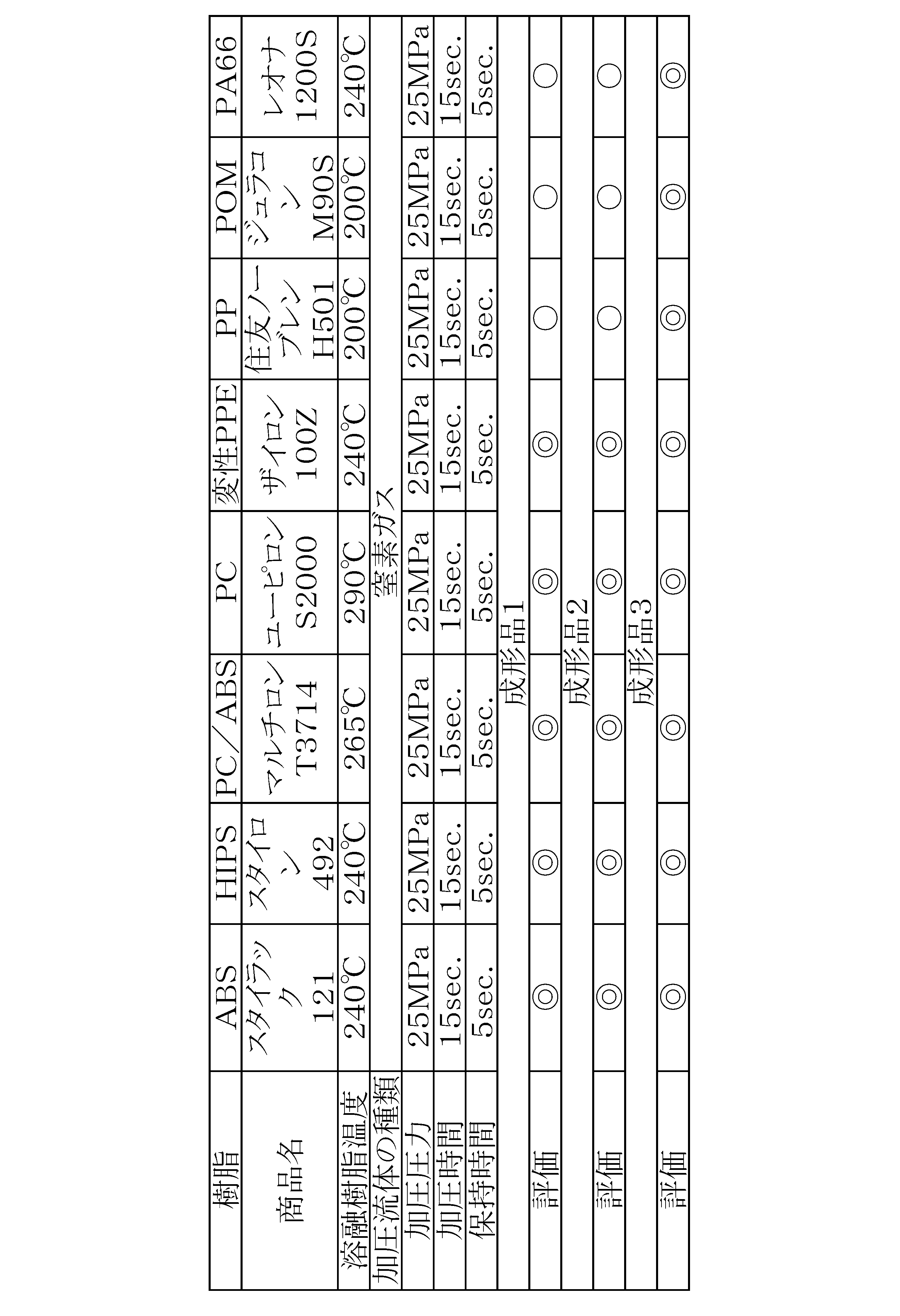


2 圧力計(窒素ボンベ1内の圧力を示す圧力計)
3 バルブ(窒素ガスボンベの交換の際に閉じる手動バルブ)
4 レギュレーター(窒素ガスボンベの圧力を調整するレギュレーター)
5 圧力計(レギュレーター4の設定の圧力を確認する圧力計)
6 逆止弁
7 圧力計(ガスブースターの中間段の圧縮時の圧力を確認する圧力計)
8 ガスブースター(窒素ガスを圧縮するガスブースター)
9 圧力計(レシーバータンク10内の圧力を確認する圧力計)
10 レシーバータンク(圧縮した高圧の窒素ガスを蓄圧するレシーバータンク)
11 バルブ(タンク10内のガスを抜く手動バルブ(ドレンバルブ))
12 レギュレーター(キャビティ内の樹脂を加圧する際は、加圧流体の圧力を設定するレギュレーター。設定圧力を確認する圧力計は図示せず。)
13 圧力計(加圧流体の圧力を確認する圧力計)
14 自動開閉弁(キャビティ内に加圧流体を入れる自動開閉弁)
15 自動開閉弁(注入した加圧流体を大気放出する自動開閉弁)
16 加圧流体の流れ方向
17 配管
18 加圧流体の排気(ブローアウト)の方向
19 タンク10内の加圧流体をドレンした場合の排気ガスの流れ方向
20 大気中であることを示す
21 キャビティ
22 固定側の取り付け板
23 可動側の取り付け板
24 スプールブッシュ
25 成形品のスプール
26 金型のパーティング
27 エジェクターピン
28 エジェクタープレート上
29 エジェクタープレート下
30 固定側の金型キャビティ
31 可動側の金型キャビティ
32 固定側の入子
33 固定側の入子の合わせ部分の隙間
34 可動側の入子
35 可動側の入子の合わせ部分の隙間
36 固定側に設けたスライドコア
37 可動側に設けたスライドコア
38 シール(スプールブッシュからの加圧流体の漏れを防ぐ目的で設置したシール)
39 シール(固定、および可動の取り付け板と型板の間のシール)
40 シール(パーティングの設置したシール)
41 シール(固定側に設けたスライドコアのパーティング面のシール)
42 シール(可動側に設けたスライドコアのパーティング面のシール)
43 シール(エジェクタープレートの設けたシール)
44 プレート(固定側の入子下のシールプレート下)
45 プレート(固定側の入子下のシールプレート上)
46 シール(固定側の入子下のシールプレート44と45の間に設けたシール)
47 加圧流体の流れ方向(ただし固定側の部分は可動側などと同様なので図示せず。)
48 繋ぎ口(加圧流体の図1、または図46の装置との金型との繋ぎ口)
49 加圧流体の通路
50 加圧ピン
51 破線(エジェクター機構を閉空間に閉じ込め密封(エジェクターボックス構造)したことを示す破線51
52 空間(エジェクターボックス52によって作られた空間)
53 プレート(可動側の入子下のシールプレート下)
54 プレート(可動側の入子下のシールプレート上)
55 シール(可動側の入子下のシールプレート53と54の間に設けたシール)
56 注入手段(エジェクターボックス51内への加圧流体の注入手段56は繋ぎ口48と加圧流体の通路49で構成されている。)
57 注入手段(キャビティ内の樹脂に直接加圧流体を作用させ、キャビティ内の樹脂を固定側から直接に加圧する注入手段57は、繋ぎ口48と加圧流体の通路49と加圧ピン50で構成されている。)
58 注入手段(キャビティ内の樹脂に直接加圧流体を作用させ、キャビティ内の樹脂を可動側から直接に加圧する注入手段58は、繋ぎ口48と加圧流体の通路49と加圧ピン50で構成されている。)
59 注入手段(固定側のスライドコアからキャビティ内の樹脂に直接加圧流体を作用させる加圧する注入手段59は、繋ぎ口48と加圧流体の通路49と加圧ピン50で構成されている。)
60 注入手段(可動側のスライドコアからキャビティ内の樹脂に直接加圧流体を作用させる加圧する注入手段60は、繋ぎ口48と加圧流体の通路49と加圧ピン50で構成されている。)
61 注入手段(加圧流体を固定側の入子の隙間33を通じてキャビティ内に入れ樹脂を固定側から加圧する注入手段61は、繋ぎ口48と加圧流体の通路49と加圧ピン50で構成されている。)
62 弁(キャビティ内に樹脂が充填された時に、キャビティ内の空気をパーティングから外に逃がし、ショート・モールドや変色・焼けの発生を解決する自動開閉弁)
63 通路(キャビティ内の空気をパーティング、入子などに設けられたガスベントなどから排気する金型内の通路)
64 ホース(キャビティ内の空気の排気用に設けた弁62、弁67、弁68などに繋ぐ耐圧ホース)
65 キャビティ内の空気の排気の流れ方向
66 大気中に放出されたキャビティ内の空気
67 弁(固定側のプレート44とプレート45に繋がれた自動開閉弁62と同じ作用をする自動開閉弁)
68 弁(固定側のプレート44とプレート45に繋がれた自動開閉弁62と同じ作用をする自動開閉弁)
69 外筒
70 鍔部
71 内芯
72 D面(Dカットし、加圧流体の通路としている。)
73 内芯71の先端部
74 D面
75 六角形状
76 継ぎ手
77 内芯71の入る部分
78 固定側の型板
79 内芯71の鍔部の入る部分(Oリングは、線接触なのでシール性が低い、発明者はゴムシートを円形にカットしてもちいることで、面接触にしてシール性を高めた。)
80 穴
81 溝(キャビティ内の空気の排気と加圧流体の通路)
82 溝(シールリング89を納める溝)
83 穴(エジェクターピンを入れ込む穴)
84 穴(加圧ピン50を入れ込む穴)
85 穴(加圧ピン50の鍔部を納める穴)
86 穴(図3の空気を逃がす通路63の穴の詳細を示している。)
87 可動側の型板
89 シールリング(エジェクターピンにシールに為に設置したシールリング)
90 シールリング(真空引きをした場合にエジェクターピンからの空気の侵入を防ぐ為に設置したシールリング)
91 シール(真空引きをした場合にプレート53とプレート92の隙間からエアーの侵入を防ぐ。)
92 プレート(シールリング90を押さえる為のプレート)
93 シール(可動側型板87とプレート54の間に設けたシールでこの隙間からの加圧流体の漏れを防ぐ。固定側型板78とプレート44の間にも図示されていないが同じ作用をするシールが設置される。)
94 ガスベント
95 溝
96 溝
97 穴(排気ガス回路63の穴)
98 繋ぎ口(図3の弁62の繋ぎ口)
99 入子のガスベント
100 通路(キャビティ内に空気の排気の通路、加圧流体の通路)
101 溝(ガスベント99に通じる溝での排気通路63に繋がっている。プレート53とプレート54の間に加圧流体を入れ、入子の隙間からキャビティ内の樹脂を加圧する場合の加圧流体の通路)
102 空間(クッション性をもたせる目的で設けた小空間で、必ずしも設ける必要はない。)
103 樹脂部分
104 スプリング
105 シボ
106 セラミック皮膜
107 光沢面
108 ゲート(サイドゲートとした)
109 加圧流体ピンの先端
110 可動側の加圧部分
111 固定側の加圧部分
112 可動側のスライドコアの加圧部分
113 固定側のスライドコアの加圧部分
115 注入手段
116 注入手段(プレート53とプレート54の間に加圧流体を入れ通路となる溝81を通じて入子の隙間や、エジェクターピンの隙間などからキャビティ内に樹脂を加圧する)
117 内芯71の鍔部
118 鍔部117のD面(Dカットし、加圧流体の通路としている。)
119 先端部
120 U溝(U溝が掘ってあって、加圧流体の通路になっている。)
121 穴
122 六角レンチの穴
123 ネジ部
124 成形品
126 Oリング(シール)
127 セットビス
128 加圧流体
129 薄肉部分
130 ボス
131 U溝(U溝が掘ってあって、加圧流体の通路になっている。)
132 外筒
133 内芯
134 D面
135 鍔部
136 成形品のボス
140 加圧流体製造装置
141 シール金型、
142 シール金型
200 キャビティ、成形空間
201 固定側の金型
202 可動側の金型
203 芯体部
204 加圧ピン(直接加圧)
205 第一型
206 第二型
207 鍔部
208 凹部
209 開口部
210 成形品
211 リブ(加圧流体を止める目的で設けてあるリブである。)
212 加圧ピン(間接加圧)
213 凹部
214 入子
215 入子
216 成形品
217 面
218 エジェクターピンの周りのガスリブ
219 エジェクターピンとリブ218との隙間
220 φ20の粗いシボ加工
221 入子34に芯体部203が収まる形状加工したことを示す模式図
222 シール
223 加圧流体が吹き出す部分
224 外筒
225 内芯
226 芯体部
227 エジェクタースリーブを加工して、加圧流体の通路をもたせたエジェクターピン
228 シール
229 シール
230 シ-ル
231 エジェクターピンを入れる段付き穴
232 エジェクターピンを入れる段付き穴
233 エジェクターピンを入れる段付き穴
234 エジェクターピンを入れる段付き穴
235 エジェクターピンを入れる段付き穴
236 溝
237 溝
238 溝
239 溝
240 溝
241 凸形状
242 凹形状
243 シール
1100 ヒケ発生の場所
1101 ヒケ発生の場所
1102 ヒケ発生の場所
1140 加圧流体製造装置
Claims (7)
- 成形空間を形成する第一型および第二型の少なくとも一方に設けられ、該成形空間に射出される樹脂により成形される成形品を押し出す軸体と、
該軸体を支持する環状弾性部材であって、周方向に沿って形成された溝の開口部が該成形空間に向けられた該環状弾性部材と、
該第一型および該第二型の少なくとも一方に設けられ、該成形空間に加圧流体を注入する注入部と、
を有する金型装置。 - さらに、前記成形空間に前記樹脂の射出を終えるまで、前記成形空間の空気を排出する排出部を有する請求項1に記載の金型装置。
- 前記軸体を支持する前記環状弾性部材は、
周方向に沿って形成された溝の開口部が前記成形空間に向けられた第1の環状弾性部材と、
周方向に沿って形成された溝の開口部が前記成形空間とは反対の方向に向けられた第2の環状弾性部材と、
からなる請求項2に記載の金型装置。 - 前記軸体を支持する前記環状弾性部材は、さらに、開口部が前記成形空間とは反対の方向に向けられた第2の溝を有する請求項2に記載の金型装置。
- 請求項1~4のいずれか1つに記載の金型装置と、
前記金型装置に前記樹脂を射出する射出装置と、
を有する射出成形システム。 - 請求項1に記載の金型装置の前記成形空間に前記樹脂を射出する第1工程と、
前記成形空間内の前記樹脂と前記成形空間を画定する前記第一型または前記第二型の面との間に前記注入部から前記加圧流体を注入する第2工程と、
前記第一型と前記第二型を型開きした後、前記成形空間内の前記樹脂により形成される前記成形品を前記軸体により押し出す第3工程と、
を有する成形品の製造方法。 - 請求項2~4のいずれか1つに記載の金型装置の前記成形空間の空気を前記排出部から排出しつつ、前記成形空間に前記樹脂を射出する第1工程と、
前記成形空間内の前記樹脂と前記成形空間を画定する前記第一型または前記第二型の面との間に前記注入部から前記加圧流体を注入する第2工程と、
前記第一型と前記第二型を型開きした後、前記成形空間内の前記樹脂により形成される前記成形品を前記軸体により押し出す第3工程と、
を有する成形品の製造方法。
Priority Applications (5)
| Application Number | Priority Date | Filing Date | Title |
|---|---|---|---|
| KR1020177015191A KR101992701B1 (ko) | 2014-11-04 | 2015-07-02 | 금형장치, 사출성형시스템, 성형품의 제조 방법 |
| US15/522,772 US11465321B2 (en) | 2014-11-04 | 2015-07-02 | Mold device, injection molding system and method for manufacturing molded article |
| JP2015532992A JP6602670B2 (ja) | 2014-11-04 | 2015-07-02 | 金型装置、射出成形システム、成形品の製造方法 |
| CN201580058428.4A CN107073783B (zh) | 2014-11-04 | 2015-07-02 | 模具装置、注射成型系统、成型制品的制造方法 |
| EP15856795.8A EP3228434B8 (en) | 2014-11-04 | 2015-07-02 | Mold device, injection molding system, and method for manufacturing molded article |
Applications Claiming Priority (2)
| Application Number | Priority Date | Filing Date | Title |
|---|---|---|---|
| JP2014224717 | 2014-11-04 | ||
| JP2014-224717 | 2014-11-04 |
Publications (1)
| Publication Number | Publication Date |
|---|---|
| WO2016072112A1 true WO2016072112A1 (ja) | 2016-05-12 |
Family
ID=55908845
Family Applications (1)
| Application Number | Title | Priority Date | Filing Date |
|---|---|---|---|
| PCT/JP2015/069216 Ceased WO2016072112A1 (ja) | 2014-11-04 | 2015-07-02 | 金型装置、射出成形システム、成形品の製造方法 |
Country Status (6)
| Country | Link |
|---|---|
| US (1) | US11465321B2 (ja) |
| EP (1) | EP3228434B8 (ja) |
| JP (1) | JP6602670B2 (ja) |
| KR (1) | KR101992701B1 (ja) |
| CN (1) | CN107073783B (ja) |
| WO (1) | WO2016072112A1 (ja) |
Cited By (3)
| Publication number | Priority date | Publication date | Assignee | Title |
|---|---|---|---|---|
| CN109723430A (zh) * | 2018-11-21 | 2019-05-07 | 长江大学 | 一种基于环空返出流量监测曲线的固井漏失与井涌分析设备及分析方法 |
| CN115871178A (zh) * | 2021-09-28 | 2023-03-31 | 丰田自动车株式会社 | 注射成型机以及注射成型方法 |
| WO2026033818A1 (ja) * | 2024-08-09 | 2026-02-12 | 康公 鈴木 | 樹脂成形体と、その製造方法、及び製造装置。溶融樹脂の流動性の向上付与の手段。 |
Families Citing this family (11)
| Publication number | Priority date | Publication date | Assignee | Title |
|---|---|---|---|---|
| US11511468B2 (en) * | 2016-01-06 | 2022-11-29 | Yasuhiro Suzuki | Mold device, injection molding system and method for manufacturing molded article |
| KR101997014B1 (ko) * | 2018-01-08 | 2019-07-05 | 오세윤 | 사출 성형 장치 |
| CN108297327A (zh) * | 2018-02-06 | 2018-07-20 | 南通海利特橡塑机械有限公司 | 一种自动热压机 |
| CN108621382A (zh) * | 2018-05-10 | 2018-10-09 | 常州星宇车灯股份有限公司 | 一种改善制品缩瘪的模具气体辅助结构及模具结构 |
| CN118240259A (zh) * | 2019-04-19 | 2024-06-25 | 铃木康公 | 一种成形机和模具的加热装置 |
| CN110774522B (zh) * | 2019-06-28 | 2022-06-14 | 东莞科威医疗器械有限公司 | 一种增强型医用插管及其成型方法 |
| US12337516B2 (en) | 2019-12-27 | 2025-06-24 | Dae San Electronics Co., Ltd. | Method of manufacturing battery cell cover and the battery cover thereof |
| CN114786910B (zh) * | 2020-01-16 | 2025-03-21 | Nok株式会社 | 成形模具及密封部件 |
| TWI794753B (zh) * | 2021-02-26 | 2023-03-01 | 田文森 | 超臨界流體射出成型機及其射出成型方法 |
| CN115256837B (zh) * | 2022-03-04 | 2025-11-11 | 青岛海尔模具有限公司 | 一种顶棍自动平衡装置、控制方法及注塑机 |
| CN117382111B (zh) * | 2023-12-11 | 2024-02-20 | 湖南四维模塑科技有限公司 | 一种汽车零部件加工用注塑模具 |
Citations (6)
| Publication number | Priority date | Publication date | Assignee | Title |
|---|---|---|---|---|
| JPS6085665U (ja) * | 1983-11-11 | 1985-06-13 | 三菱電線工業株式会社 | ノンステイツクスリツプ摺動用シ−ル |
| JPH10119077A (ja) * | 1996-10-21 | 1998-05-12 | Asahi Chem Ind Co Ltd | ガス併用射出成形方法 |
| JPH11101348A (ja) * | 1997-09-30 | 1999-04-13 | Kyoritsu Packing Kk | シール部材 |
| JPH11216746A (ja) * | 1998-02-02 | 1999-08-10 | Asahi Chem Ind Co Ltd | カウンタプレッシャ成形用金型 |
| JPH11216748A (ja) * | 1998-02-02 | 1999-08-10 | Asahi Chem Ind Co Ltd | シール金型 |
| JP2011255541A (ja) * | 2010-06-07 | 2011-12-22 | Canon Inc | ガスアシスト射出成形用金型とガスアシスト射出成形方法 |
Family Cites Families (6)
| Publication number | Priority date | Publication date | Assignee | Title |
|---|---|---|---|---|
| US4479914A (en) | 1982-11-01 | 1984-10-30 | Cashiers Plastics | Process and mold for molding foamed plastic articles |
| US4508356A (en) | 1984-06-06 | 1985-04-02 | Robert Janian | Modified C-shaped mechanical spring seal |
| TW429213B (en) * | 1996-09-03 | 2001-04-11 | Asahi Chemical Ind | Method for molding thermoplastic resin |
| WO2005018902A1 (ja) * | 2003-08-22 | 2005-03-03 | Suzuka Fuji Xerox Co., Ltd. | 中空成形品、中空成形品の製造方法および中空成形用金型 |
| JP3838372B2 (ja) * | 2004-06-08 | 2006-10-25 | トヨタ自動車株式会社 | 射出成形方法と射出成形装置 |
| JP5049721B2 (ja) | 2007-09-28 | 2012-10-17 | 三甲株式会社 | 合成樹脂製パレット用金型構造 |
-
2015
- 2015-07-02 KR KR1020177015191A patent/KR101992701B1/ko active Active
- 2015-07-02 JP JP2015532992A patent/JP6602670B2/ja active Active
- 2015-07-02 EP EP15856795.8A patent/EP3228434B8/en active Active
- 2015-07-02 CN CN201580058428.4A patent/CN107073783B/zh active Active
- 2015-07-02 WO PCT/JP2015/069216 patent/WO2016072112A1/ja not_active Ceased
- 2015-07-02 US US15/522,772 patent/US11465321B2/en active Active
Patent Citations (6)
| Publication number | Priority date | Publication date | Assignee | Title |
|---|---|---|---|---|
| JPS6085665U (ja) * | 1983-11-11 | 1985-06-13 | 三菱電線工業株式会社 | ノンステイツクスリツプ摺動用シ−ル |
| JPH10119077A (ja) * | 1996-10-21 | 1998-05-12 | Asahi Chem Ind Co Ltd | ガス併用射出成形方法 |
| JPH11101348A (ja) * | 1997-09-30 | 1999-04-13 | Kyoritsu Packing Kk | シール部材 |
| JPH11216746A (ja) * | 1998-02-02 | 1999-08-10 | Asahi Chem Ind Co Ltd | カウンタプレッシャ成形用金型 |
| JPH11216748A (ja) * | 1998-02-02 | 1999-08-10 | Asahi Chem Ind Co Ltd | シール金型 |
| JP2011255541A (ja) * | 2010-06-07 | 2011-12-22 | Canon Inc | ガスアシスト射出成形用金型とガスアシスト射出成形方法 |
Non-Patent Citations (1)
| Title |
|---|
| See also references of EP3228434A4 * |
Cited By (3)
| Publication number | Priority date | Publication date | Assignee | Title |
|---|---|---|---|---|
| CN109723430A (zh) * | 2018-11-21 | 2019-05-07 | 长江大学 | 一种基于环空返出流量监测曲线的固井漏失与井涌分析设备及分析方法 |
| CN115871178A (zh) * | 2021-09-28 | 2023-03-31 | 丰田自动车株式会社 | 注射成型机以及注射成型方法 |
| WO2026033818A1 (ja) * | 2024-08-09 | 2026-02-12 | 康公 鈴木 | 樹脂成形体と、その製造方法、及び製造装置。溶融樹脂の流動性の向上付与の手段。 |
Also Published As
| Publication number | Publication date |
|---|---|
| CN107073783B (zh) | 2020-04-14 |
| EP3228434B1 (en) | 2024-06-12 |
| EP3228434A4 (en) | 2018-10-31 |
| EP3228434B8 (en) | 2024-07-17 |
| KR20170075797A (ko) | 2017-07-03 |
| US11465321B2 (en) | 2022-10-11 |
| CN107073783A (zh) | 2017-08-18 |
| US20170312965A1 (en) | 2017-11-02 |
| KR101992701B1 (ko) | 2019-06-25 |
| EP3228434A1 (en) | 2017-10-11 |
| JP6602670B2 (ja) | 2019-11-06 |
| JPWO2016072112A1 (ja) | 2017-08-10 |
Similar Documents
| Publication | Publication Date | Title |
|---|---|---|
| JP6602670B2 (ja) | 金型装置、射出成形システム、成形品の製造方法 | |
| JP6684489B2 (ja) | 金型装置、成形装置、射出成形システム、成形品の製造方法 | |
| JP6522701B2 (ja) | 発泡成形体の製造装置 | |
| JP3151485B2 (ja) | 非樹脂流体併用射出成形方法 | |
| US8168098B2 (en) | Method of injection molding thermoplastic resin using supercritical fluid and injection molding apparatus | |
| CN101068670B (zh) | 注射发泡成型方法和注射发泡成型用模具 | |
| WO2013077390A1 (ja) | 成形用金型および成形方法 | |
| KR19980024281A (ko) | 열가소성 수지의 성형 방법 | |
| CA2618845A1 (en) | Method for foam injection molding of thermoplastic resin | |
| JPH11179750A (ja) | ガス併用射出成形法 | |
| JP2002307482A (ja) | 表皮材積層熱可塑性樹脂発泡成形体の製造方法 | |
| JP2009039954A (ja) | 射出発泡成形用金型および該金型を用いた射出発泡成形体の製造方法 | |
| JP2004223888A (ja) | 熱可塑性樹脂の射出成形法 | |
| JP2001341152A (ja) | 射出成形装置 | |
| JP2012066384A (ja) | ガスアシスト成形用金型及びガスアシスト成形方法 | |
| JP2003127191A (ja) | ハイサイクル発泡射出成形法 | |
| KR20170001968A (ko) | 부분 미발포 및 발포 사출 성형용 금형 | |
| JP2005028814A (ja) | シール金型 | |
| TH79666A (th) | วิธีฉีดขึ้นรูปเกิดฟองและแม่พิมพ์สำหรับฉีดขึ้นรูปเกิดฟอง | |
| JPWO2001096084A1 (ja) | 熱可塑性樹脂の射出成形法 | |
| JP2018004003A (ja) | ライナー用加工装置 | |
| CN120129597A (zh) | 树脂成型品 | |
| JP2005313328A (ja) | 樹脂成形品の製造方法 | |
| JP2004034381A (ja) | 偏肉成形品の発泡射出成形法 | |
| JP2010143141A (ja) | 発泡成形品の製造方法 |
Legal Events
| Date | Code | Title | Description |
|---|---|---|---|
| ENP | Entry into the national phase |
Ref document number: 2015532992 Country of ref document: JP Kind code of ref document: A |
|
| 121 | Ep: the epo has been informed by wipo that ep was designated in this application |
Ref document number: 15856795 Country of ref document: EP Kind code of ref document: A1 |
|
| WWE | Wipo information: entry into national phase |
Ref document number: 15522772 Country of ref document: US |
|
| NENP | Non-entry into the national phase |
Ref country code: DE |
|
| REEP | Request for entry into the european phase |
Ref document number: 2015856795 Country of ref document: EP |
|
| ENP | Entry into the national phase |
Ref document number: 20177015191 Country of ref document: KR Kind code of ref document: A |