WO2016072206A1 - Système de communications, appareil d'émission et procédé de communications - Google Patents
Système de communications, appareil d'émission et procédé de communications Download PDFInfo
- Publication number
- WO2016072206A1 WO2016072206A1 PCT/JP2015/078510 JP2015078510W WO2016072206A1 WO 2016072206 A1 WO2016072206 A1 WO 2016072206A1 JP 2015078510 W JP2015078510 W JP 2015078510W WO 2016072206 A1 WO2016072206 A1 WO 2016072206A1
- Authority
- WO
- WIPO (PCT)
- Prior art keywords
- signal
- signals
- modulation
- modulated
- transmission
- Prior art date
- Legal status (The legal status is an assumption and is not a legal conclusion. Google has not performed a legal analysis and makes no representation as to the accuracy of the status listed.)
- Ceased
Links
Images







Classifications
-
- H—ELECTRICITY
- H04—ELECTRIC COMMUNICATION TECHNIQUE
- H04B—TRANSMISSION
- H04B7/00—Radio transmission systems, i.e. using radiation field
- H04B7/02—Diversity systems; Multi-antenna system, i.e. transmission or reception using multiple antennas
- H04B7/10—Polarisation diversity; Directional diversity
-
- H—ELECTRICITY
- H04—ELECTRIC COMMUNICATION TECHNIQUE
- H04B—TRANSMISSION
- H04B7/00—Radio transmission systems, i.e. using radiation field
- H04B7/02—Diversity systems; Multi-antenna system, i.e. transmission or reception using multiple antennas
- H04B7/04—Diversity systems; Multi-antenna system, i.e. transmission or reception using multiple antennas using two or more spaced independent antennas
- H04B7/0413—MIMO systems
- H04B7/0456—Selection of precoding matrices or codebooks, e.g. using matrices antenna weighting
-
- H—ELECTRICITY
- H04—ELECTRIC COMMUNICATION TECHNIQUE
- H04L—TRANSMISSION OF DIGITAL INFORMATION, e.g. TELEGRAPHIC COMMUNICATION
- H04L1/00—Arrangements for detecting or preventing errors in the information received
- H04L1/0001—Systems modifying transmission characteristics according to link quality, e.g. power backoff
- H04L1/0002—Systems modifying transmission characteristics according to link quality, e.g. power backoff by adapting the transmission rate
- H04L1/0003—Systems modifying transmission characteristics according to link quality, e.g. power backoff by adapting the transmission rate by switching between different modulation schemes
-
- H—ELECTRICITY
- H04—ELECTRIC COMMUNICATION TECHNIQUE
- H04L—TRANSMISSION OF DIGITAL INFORMATION, e.g. TELEGRAPHIC COMMUNICATION
- H04L1/00—Arrangements for detecting or preventing errors in the information received
- H04L1/0001—Systems modifying transmission characteristics according to link quality, e.g. power backoff
- H04L1/0002—Systems modifying transmission characteristics according to link quality, e.g. power backoff by adapting the transmission rate
- H04L1/0003—Systems modifying transmission characteristics according to link quality, e.g. power backoff by adapting the transmission rate by switching between different modulation schemes
- H04L1/0004—Systems modifying transmission characteristics according to link quality, e.g. power backoff by adapting the transmission rate by switching between different modulation schemes applied to control information
-
- H—ELECTRICITY
- H04—ELECTRIC COMMUNICATION TECHNIQUE
- H04L—TRANSMISSION OF DIGITAL INFORMATION, e.g. TELEGRAPHIC COMMUNICATION
- H04L27/00—Modulated-carrier systems
- H04L27/0008—Modulated-carrier systems arrangements for allowing a transmitter or receiver to use more than one type of modulation
-
- H—ELECTRICITY
- H04—ELECTRIC COMMUNICATION TECHNIQUE
- H04B—TRANSMISSION
- H04B7/00—Radio transmission systems, i.e. using radiation field
- H04B7/02—Diversity systems; Multi-antenna system, i.e. transmission or reception using multiple antennas
- H04B7/04—Diversity systems; Multi-antenna system, i.e. transmission or reception using multiple antennas using two or more spaced independent antennas
- H04B7/0413—MIMO systems
-
- H—ELECTRICITY
- H04—ELECTRIC COMMUNICATION TECHNIQUE
- H04B—TRANSMISSION
- H04B7/00—Radio transmission systems, i.e. using radiation field
- H04B7/02—Diversity systems; Multi-antenna system, i.e. transmission or reception using multiple antennas
- H04B7/04—Diversity systems; Multi-antenna system, i.e. transmission or reception using multiple antennas using two or more spaced independent antennas
- H04B7/06—Diversity systems; Multi-antenna system, i.e. transmission or reception using multiple antennas using two or more spaced independent antennas at the transmitting station
- H04B7/0613—Diversity systems; Multi-antenna system, i.e. transmission or reception using multiple antennas using two or more spaced independent antennas at the transmitting station using simultaneous transmission
- H04B7/0667—Diversity systems; Multi-antenna system, i.e. transmission or reception using multiple antennas using two or more spaced independent antennas at the transmitting station using simultaneous transmission of delayed versions of same signal
- H04B7/0669—Diversity systems; Multi-antenna system, i.e. transmission or reception using multiple antennas using two or more spaced independent antennas at the transmitting station using simultaneous transmission of delayed versions of same signal using different channel coding between antennas
Definitions
- the present invention relates to a communication system, a transmission device, and a communication method corresponding to a plurality of communication methods.
- Patent Literature 1 combines a polarization multiplexing transmission system using XPIC (Cross Polarization Interference Canceller) and a spatial multiplexing transmission system using a MIMO (Multiple-Input Multiple-Output) system.
- XPIC Cross Polarization Interference Canceller
- MIMO Multiple-Input Multiple-Output
- a communication method is disclosed. Since this communication method can increase the multiplicity of signals, the communication path capacity can be increased.
- the stability of the communication by the polarization multiplexing transmission method or the spatial multiplexing transmission method changes depending on the condition of the transmission path. It is difficult to secure.
- Patent Document 2 proposes adaptively switching the communication method according to the condition of the transmission path.
- Patent Document 2 does not disclose a specific communication method switching method for securing a stable transmission path.
- a communication method switching method using polarized waves such as a polarization diversity method and a polarization multiplexing transmission method, and an interference compensator suitable for these communication methods are not disclosed. For this reason, it is difficult to solve the problem of securing a stable transmission path.
- One of the objects of the present invention is to provide a communication system, a transmission device, and a communication method capable of securing a stable transmission path.
- a communication system includes a modulation unit that outputs a plurality of modulation signals modulated using a set modulation scheme, a transmission unit that transmits the plurality of modulation signals, and a plurality of transmission units that are transmitted from the transmission unit.
- the phase difference between the receiving unit that receives the modulated signal and the received signal that is the modulated signal received by the receiving unit, and the deviation of the polarization plane of the received signal from the transmitted signal that is the modulated signal transmitted from the transmitting unit A control unit that selects a communication method based on parameters according to the setting method, and a setting unit that sets a modulation method corresponding to the communication method selected by the control unit in the modulation unit.
- a receiving device includes a receiving unit that receives a plurality of modulated signals modulated by a transmitting device, a phase difference between a received signal that is a modulated signal received by the receiving unit, and a transmission from the transmitting unit.
- a control unit that selects a communication method based on a parameter corresponding to a deviation in polarization plane of a received signal from a transmission signal that is a modulated signal, and sets a modulation method corresponding to the communication method in a transmission device; Have.
- a communication method outputs a plurality of modulation signals modulated using a set modulation scheme, transmits a plurality of modulation signals, and receives a plurality of modulation signals transmitted from a transmission unit.
- the communication method is selected based on parameters according to the phase difference between the received signals that are the modulated signals and the deviation of the polarization plane of the received signals from the transmitted signals that are the transmitted modulated signals, Sets a modulation method according to the selected communication method.
- FIG. 1 is a diagram showing a communication system according to the first embodiment of the present invention.
- FIG. 2 is a diagram illustrating a configuration example of the transmission apparatus according to the first embodiment of the present invention.
- FIG. 3 is a diagram illustrating a configuration example of the receiving apparatus according to the first embodiment of the present invention.
- FIG. 4 is a diagram illustrating an example of the configuration of the modulation unit according to the first embodiment of the present invention.
- FIG. 5 is a diagram illustrating another example of the configuration of the modulation unit according to the first embodiment of the present invention.
- FIG. 6 is a diagram illustrating another example of the configuration of the modulation unit according to the first embodiment of the present invention.
- FIG. 7 is a diagram illustrating another example of the configuration of the modulation unit according to the first embodiment of the present invention.
- FIG. 8 is a diagram illustrating another example of the configuration of the modulation unit according to the first embodiment of the present invention.
- FIG. 9 is a diagram illustrating an example of the configuration of the demodulation unit according to the first embodiment of the present invention.
- FIG. 10 is a diagram illustrating another example of the configuration of the demodulation unit according to the first embodiment of the present invention.
- FIG. 11 is a diagram illustrating another example of the configuration of the demodulation unit according to the first embodiment of the present invention.
- FIG. 12 is a diagram illustrating another example of the configuration of the demodulation unit according to the first embodiment of the present invention.
- FIG. 13 is a diagram illustrating another example of the configuration of the demodulation unit according to the first embodiment of the present invention.
- FIG. 14 is a diagram illustrating an example of the configuration of the transversal filter according to the first embodiment of the present invention.
- FIG. 15 is a flowchart for explaining the operation of the communication system according to the first embodiment of the present invention.
- FIG. 1 is a diagram showing a communication system according to the first embodiment of the present invention.
- a communication system 1 illustrated in FIG. 1 includes a transmission device 100 and a reception device 200 that are communication devices compatible with a plurality of communication methods.
- the transmission device 100 transmits a plurality of modulated signals modulated using a modulation method corresponding to any of a plurality of supported communication methods to the reception device 200. Further, when receiving a control signal from the receiving apparatus 200, the transmitting apparatus 100 sets the modulation scheme used for modulation in the transmitting apparatus 100 itself based on the control signal. Specifically, the control signal indicates a communication method, and the transmission apparatus 100 sets a modulation method according to the communication method indicated by the control signal.
- the communication methods supported by the transmission apparatus 100 include the following four communication methods from the first communication method to the fourth communication method.
- the first communication method is a SISO (Single Input Single Single Output) communication method.
- the first communication method is a communication method in which a PWD (Polarized Wave Diversity) method and an SD (Space Diversity) method are combined.
- the SD method uses STBC (Space Time Block Code).
- STBC Space Time Block Code
- the first communication method instead of the communication method combining the PWD method and the STBC method, only one of the H polarization signal and the V polarization signal is used.
- a communication method to be used may be used.
- the second communication method is a communication method that combines the PWD method and the spatial multiplexing transmission method.
- the spatial multiplexing transmission method is assumed to use a MIMO system.
- the spatial multiplexing transmission method using the MIMO system is referred to as a MIMO method.
- the third communication method is a communication method combining the polarization multiplexing transmission method and the STBC method.
- the polarization multiplexing transmission method compensates for interference using XPIC that compensates for cross-polarization interference.
- XPIC system a polarization multiplexing transmission system using XPIC is referred to as an XPIC system.
- the fourth communication method is a communication method combining the XPIC method and the MIMO method. This communication method is sometimes called a 4 ⁇ 4 MIMO method.
- the receiving apparatus 200 receives a plurality of transmission signals that are modulated signals transmitted by the transmitting apparatus 100 and demodulates the received signals that are the received modulated signals. In addition, the receiving device 200 calculates a parameter according to the state of the transmission path between the transmitting device 100 and the receiving device 200, and controls to select one of a plurality of corresponding communication methods based on the calculated parameter.
- a circuit 300 is included.
- the control circuit 300 is a control unit that sets a modulation scheme corresponding to the selected communication scheme in the transmission apparatus 100 by notifying the transmission apparatus 100 of a control signal indicating the selected communication scheme.
- FIG. 2 is a diagram illustrating a configuration example of the transmission device 100.
- the transmission apparatus 100 shown in FIG. 2 includes transmission antennas 101 and 102, a modulation unit (MOD: Modulator unit) 103, a setting unit 104, a local oscillator 105, and transmission circuits (Tx) 106 to 109.
- MOD Modulator unit
- Tx transmission circuits
- Each of the transmission antennas 101 and 102 is a polarization sharing antenna capable of transmitting two different polarization signals.
- the two polarization signals are a V (Vertical) polarization signal and an H (Horizontal) polarization signal.
- the transmission antennas 101 and 102 are installed at an interval dT suitable for the MIMO scheme.
- the modulation unit 103 is set with a modulation method according to any of a plurality of communication methods supported by the transmission device 100. Modulation section 103 then outputs a plurality of modulated signals modulated using the set modulation scheme to transmission circuits 106-109, respectively. In this embodiment, a maximum of four signals S1 to S4 are input to the modulation unit 103, and four modulated signals obtained by modulating the input signals are output.
- the signals S1 to S4 input to the modulation unit 103 are BB (Base-Band) signals, and the modulation signal output from the modulation unit 103 is an IF (Intermediate Frequency) signal.
- the setting unit 104 receives a control signal from the receiving device 200, and sets a modulation method corresponding to the communication method indicated by the received control signal in the modulation unit 103.
- the local oscillator 105 generates an oscillation signal for converting the IF signal into an RF (Radio Frequency) signal and supplies it to the transmission circuits 106 to 109.
- the local oscillator 105 is depicted as being connected only to the transmission circuits 107 and 108, but in reality, all of the transmission circuits 106 to 109 are illustrated. It is connected.
- the transmission circuits 106 to 109 constitute a transmission unit that transmits the modulated signal output from the modulation unit 103. Specifically, each of the transmission circuits 106 to 109 receives a different modulation signal among the four modulation signals output from the modulation unit 103. Then, the transmission circuits 106 to 109 convert the input modulation signal into an RF signal using the oscillation signal from the local oscillator 105 and transmit it to the reception device 200 via the transmission antenna 101 or 102. In this embodiment, the transmission circuits 106 and 107 transmit RF signals via the transmission antenna 101, and the transmission circuits 108 and 109 transmit RF signals via the transmission antenna 102. Further, the transmission circuits 106 to 109 may perform processing such as amplifying the RF signal to a predetermined transmission output level.
- FIG. 3 is a diagram illustrating a configuration example of the receiving device 200.
- the receiving apparatus 200 shown in FIG. 3 includes receiving antennas 201 and 202, a local oscillator 203, receiving circuits (Rx) 204 to 207, a demodulating unit (DEM: Demodulator unit) 208, and a control circuit 300.
- Rx receiving circuits
- DEM Demodulating unit
- the receiving antennas 201 and 202 are dual-polarization antennas that can receive two different polarization signals.
- the two polarization signals are the V polarization signal and the H polarization signal as described above.
- the receiving antennas 201 and 202 are installed at an interval dR suitable for the MIMO system. Note that the interval dR can be set to the same interval as the interval dT between the transmission antennas 101 and 102 of the transmission apparatus 100, for example.
- the local oscillator 203 generates an oscillation signal for converting the RF signal into an IF signal and supplies the generated oscillation signal to the receiving circuits 204 to 207.
- the local oscillator 203 is depicted as being connected only to the receiving circuits 205 and 206 in order to simplify the drawing, but in practice, the local oscillator 203 is connected to all of the receiving circuits 204 to 207. It is connected.
- the reception circuits 204 to 207 constitute a reception unit that receives RF signals that are a plurality of transmission signals transmitted by the transmission device 100. Specifically, the receiving circuits 204 to 207 receive an RF signal via the receiving antenna 201 or 202, and separate the received RF signal into a V polarization signal and an H polarization signal. Each of the receiving circuits 204 to 207 converts one of the separated V polarization signal and H polarization signal into an IF signal using the RF oscillation signal from the local oscillator 203, and converts the converted IF signal. Input to demodulator 208.
- the receiving circuits 204 and 205 receive the RF signal via the receiving antenna 201
- the receiving circuits 206 and 207 receive the RF signal via the receiving antenna 202
- the reception circuits 204 and 206 input the V polarization signal to the demodulation unit 208
- the reception circuits 205 and 207 input the H polarization signal to the demodulation unit 208.
- the separation into the V-polarized signal and the H-polarized signal is not usually performed completely, and each of the V-polarized signal and the H-polarized signal includes an interference component with the other polarized signal. It is.
- the demodulation unit 208 demodulates and outputs each IF signal input from the receiving circuits 204 to 207.
- a maximum of four signals S1_OUT to S4_OUT are output from the demodulation unit 208 according to the modulation scheme by the transmission apparatus 100.
- the control circuit 300 uses the phase difference between the reception signals received by the reception circuits 204 to 207 and the transmission signal transmitted by the transmission device 100 as parameters according to the state of the transmission path between the transmission device 100 and the reception device 200.
- the parameter corresponding to the deviation of the polarization plane of the received signal is calculated.
- the parameters include a first parameter X corresponding to the phase difference between the received signals and a second parameter Y corresponding to the deviation of the polarization plane of the received signal from the transmitted signal.
- the demodulation unit 208 is used for the singular value of the channel matrix between the transmission antennas 101 and 102 of the transmission device 100 and the reception antennas 201 and 202 of the reception device 200, and the XPIC provided in the demodulation unit 208. And a tap coefficient of a transversal filter to be obtained. Then, the control circuit 300 calculates a parameter based on the singular value and the tap coefficient obtained by the demodulation unit 208. A more detailed parameter calculation method will be described later.
- the control circuit 300 selects a communication method based on the calculated parameters, and notifies the transmission device 100 of a control signal indicating the selected communication method, so that the modulation method corresponding to the selected communication method is transmitted to the transmission device 100. Set.
- the control circuit 300 determines whether or not the phase difference falls within the first allowable range and whether or not the polarization plane deviation falls within the second allowable range. In the present embodiment, the control circuit 300 determines that the phase difference is within the first allowable range when the first parameter X is equal to or greater than the first threshold value, and the second parameter is less than the second threshold value. Then, it is determined that the deviation of the polarization plane falls within the second allowable range.
- the control circuit 300 selects a communication method based on the determination result. Specifically, when the phase difference does not fall within the first allowable range, the control circuit 300 selects the communication scheme including the STBC scheme, and when the phase difference falls within the first allowable range, the communication scheme including MIMO. Select.
- the control circuit 300 selects the communication method including the PWD method when the polarization plane deviation does not fall within the second allowable range, and includes the XPIC method when the polarization plane deviation falls within the second allowable range. Select the communication method.
- the correspondence between communication methods and parameters is as shown in Table 1 below. In Table 1, the communication capacity in each communication method when the communication capacity in the first communication method (PWD method + STBC method) is C is also shown.
- FIG. 4 is a block diagram illustrating an example of the configuration of the modulation unit 103.
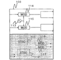
- the modulation unit 103 shown in FIG. 4 includes time code addition circuits (STBC) 111 and 112, a local oscillator 113, and modulators 114 to 117.
- STBC time code addition circuits
- the time code adding circuits 111 and 112 output two signals obtained by encoding the input signal using the STBC.
- the local oscillator 113 generates an oscillation signal for converting the BB signal into an IF signal and supplies it to the modulators 114 to 117.
- Modulators 114 to 117 use the oscillation signal from local oscillator 113 to modulate the input BB signal into an IF signal and output the IF signal. Note that the modulators 114 to 117 also perform multilevel modulation on the input BB signal.
- the local oscillator 113 is depicted as being connected only to the modulators 115 and 116 in order to simplify the drawing, but in practice, the local oscillators 113 are all connected to the modulators 114 to 117. It is connected.
- the setting unit 104 shown in FIG. 2 sets the modulation method in the modulation unit 103 by switching the connection relationship in the modulation unit 103 based on the communication method indicated by the control signal.
- FIG. 5 is a block diagram illustrating a configuration of the modulation unit 103 in which a modulation scheme corresponding to the first communication scheme is set.
- any one of the input signals S 1 to S 4 (input signal S 1) is input to the time code adding circuit 111.
- One of the signals encoded by the time code adding circuit 111 is branched into two and input to the modulators 114 and 116, and the other of the signals encoded by the time code adding circuit 111 is branched into two.
- the signals modulated by the modulators 114 to 117 are input to the transmission circuits 106 to 109, respectively.
- the input signal S1 encoded by STBC is transmitted from each of the transmission antennas 101 and 102 as a V polarization signal and an H polarization signal. Therefore, the input signal S1 is transmitted by the first communication method that combines the PWD method and the STBC method.
- FIG. 6 is a block diagram illustrating a configuration of the modulation unit 103 in which a modulation scheme corresponding to the second communication scheme is set.
- any two of input signals S1 to S4 (input signals S1 and S2) are input to modulators 114 and 115, respectively.
- the input signal S1 modulated by the modulator 114 is branched into two and input to the transmission circuits 106 and 107, and the input signal S2 modulated by the modulator 115 is branched into two and the transmission circuits 108 and 109. Is input.
- the input signal S1 is transmitted from the transmission antenna 101 as a V polarization signal and an H polarization signal
- the input signal S2 is transmitted from the transmission antenna 102 as a V polarization signal and an H polarization signal. Will be sent. Therefore, the input signals S1 and S2 are transmitted by the second communication method that combines the PWD method and the MIMO method.
- FIG. 7 is a block diagram illustrating a configuration of the modulation unit 103 in which a modulation scheme corresponding to the third communication scheme is set.
- any two of the input signals S1 to S4 (input signals S1 and S2) are input to the time code adding circuits 111 and 112, respectively.
- Signal S1 encoded by time code adding circuit 111 is input to modulators 114 and 115, respectively, and signals encoded by time code adding circuit 112 are input to modulators 116 and 117, respectively.
- Signals modulated by modulators 114 and 115 are input to transmission circuits 106 and 108, respectively, and input signal S2 modulated by modulators 116 and 117 is input to transmission circuits 107 and 109, respectively.
- the input signal S1 encoded by STBC is transmitted as a V polarization signal from the transmission antennas 101 and 102, and the input signal S2 encoded by STBC is transmitted by the transmission antenna 101. And 102 are transmitted as H polarization signals. Therefore, the input signals S1 and S2 are transmitted by the third communication method that combines the XPIC method and the STBC method.
- FIG. 8 is a block diagram illustrating a configuration of the modulation unit 103 in which a modulation method corresponding to the fourth communication method is set.
- input signals S1 to S4 are input to modulators 114 to 119, respectively.
- Input signals S1 to S4 modulated by modulators 114 to 119 are input to transmission circuits 106 to 09, respectively.
- the input signal S1 is transmitted as a V polarization signal from the transmission antenna 101, and the input signal S2 is transmitted as an H polarization signal from the transmission antenna 101. Further, the input signal S3 is transmitted from the transmission antenna 102 as a V polarization signal, and the input signal S4 is transmitted from the transmission antenna 102 as an H polarization signal. Therefore, the input signals S1 to S4 are transmitted by the fourth communication method that combines the XPIC method and the MIMO method.
- FIG. 9 is a block diagram illustrating an example of the configuration of the demodulation unit 208.
- 9 includes a local oscillator 210, amplitude phase adjustment units 211A and 211B, interference compensators (DEMXPICs) 212A to 212D, MIMO units 213A and 213B, demodulators 214A and 214B, space-time It has code removal circuits 215A and 215B.
- DEMXPICs interference compensators
- the local oscillator 210 generates and outputs an oscillation signal for converting the IF signal into a BB signal.
- V amplitude and H polarization signals received via the same antenna are input to the amplitude phase adjustment units 211A and 211B, respectively.
- Each of amplitude phase adjustment sections 211A and 211B adjusts the amplitude and phase of each of the input V polarization signal and H polarization signal, and multiplies the adjusted V polarization signal and H polarization signal to output them. To do.
- each of the amplitude phase adjustment units 211A and 211B includes amplitude phase adjustment circuits (APC) 9A and 9B, and a multiplier 9C.
- Amplitude phase adjustment circuits 9A and 9B adjust the amplitude and phase of the input signal (V polarization signal or H polarization signal) and output the result.
- Multiplier 9C multiplies the signals output from amplitude phase adjustment circuits 9A and 9B and outputs the result.
- Interference compensators 212A to 212D include an XPIC (not shown) that compensates for cross-polarization interference, and outputs a signal whose cross-polarization interference has been compensated by the XPIC.
- Two IF signals multiplexed by spatial multiplexing are input to the MIMO units 213A and 213B.
- the signals multiplexed by spatial multiplexing are the same polarization signals received by different receiving antennas.
- MIMO sections 213A and 213B separate the input multiplexed signals.
- the MIMO units 213A and 213B have a demodulation circuit (DEM) 9D and a MIMO signal processing circuit (MIMO) 9E.
- the demodulating circuit 9D uses the oscillation signal from the local oscillator 210 to convert each of the two input IF signals into a BB signal, and further converts the BB signal into a digital signal. Then, the demodulation circuit 9D calculates each element of the channel matrix that performs correlation calculation between the pilot signal added to the BB signal converted into the digital signal and the signal to be demodulated in the BB signal, and BB.
- the signal and the element signal indicating each element are input to the MIMO signal processing circuit 9E.
- the MIMO signal processing circuit 9E calculates a matrix composed of elements indicated by the input element signal with respect to the input BB signal, and outputs the BB signal separated into two multiplexed signals. .
- Each of the demodulators 214A and 214B has two demodulation circuits (DEM) 9F and 9G that demodulate and output an input signal, respectively.
- Each of the demodulation circuits 9F and 9G can demodulate the input IF signal into a BB signal using the oscillation signal from the local oscillator 210 when the input signal is an IF signal that is not spatially multiplexed. it can.
- Each of the demodulation circuits 9F and 9G can demodulate multi-level modulation when the input signal is a signal separated by the MIMO unit 213A or 213B.
- the space-time code removal circuits 215A and 215B perform decoding corresponding to STBC on the input signal.
- the demodulator 208 switches the connection relationship inside the demodulator 208 according to the modulation scheme set in the transmission apparatus 100 and sets a demodulation scheme corresponding to the modulation scheme set in the transmission apparatus 100. For example, a pilot signal indicating a modulation scheme set in the modulation unit 103 by the setting unit 104 of the transmission device 100 is added to a signal transmitted from the transmission device 100, and the demodulation unit 208 is added to a pilot signal added to the received signal.
- the demodulation method can be set according to the signal.
- FIG. 10 is a block diagram showing a configuration of the demodulation unit 208 in which a demodulation method corresponding to the first communication method is set.
- signals input to the demodulation unit 208 are referred to as signals T1 to T4.
- the signal T1 is a V polarization signal received via the reception antenna 201
- the signal T2 is an H polarization signal received via the reception antenna 201.
- the signal T3 is a V polarization signal received via the reception antenna 202
- the signal T4 is an H polarization signal received via the reception antenna 202.
- the received signals T1 and T2 are input to the amplitude / phase adjusting unit 211A, and the received signals T3 and T4 are input to the amplitude / phase adjusting unit 211B.
- Signals output from each of the amplitude and phase adjustment units 211A and 211B are input to the demodulator 214A.
- the demodulator 214A demodulates the input signal using the oscillation signal from the local oscillator 210 and inputs the demodulated signal to the space-time code removal circuit 215A. Then, the signal decoded by the space-time code removal circuit 215A is output.
- FIG. 11 is a block diagram showing a configuration of the demodulator 208 in which a demodulation method corresponding to the second communication method is set.
- the received signals T1 and T2 are input to the amplitude / phase adjusting unit 211A
- the received signals T3 and T4 are input to the amplitude / phase adjusting unit 211B.
- Signals output from each of the amplitude phase adjustment units 211A and 211B are input to the MIMO unit 213A.
- the signal separated by MIMO section 213A is input to demodulator 214A.
- the signal demodulated by the multilevel modulation is output by the demodulator 214A.
- FIG. 12 is a block diagram showing a configuration of the demodulator 208 in which a demodulation scheme corresponding to the third communication scheme is set.
- each of signals T1 and T2 is branched into two and input to interference compensators 212A and 212B, and each of signals T3 and T4 is branched into two and input to interference compensators 212C and 212D. Is done.
- the signals output from the interference compensators 212A and 212B are input to the demodulator 214A, and the signals output from the interference compensators 212C and 212DB are input to the demodulator 214B.
- the signal output from demodulator 214A is input to space-time code removal circuit 215A, and the signal output from demodulator 214B is input to space-time code removal circuit 215B. Then, the signals decoded by the space-time code removal circuits 215A and 215B are output.
- FIG. 13 is a block diagram showing a configuration of the demodulator 208 in which a demodulation method corresponding to the third communication method is set.
- signals T1 and T3 are input to MIMO section 213A
- signals T2 and T4 are input to MIMO section 213B.
- One of the signals output from the MIMO unit 213A is input to the interference compensators 212A and 212B, and the other of the signals output from the MIMO unit 213A is input to the interference compensators 212C and 212D.
- one of the signals output from MIMO section 213B is input to interference compensators 212A and 212B, and the other of the signals output from MIMO section 213B is input to interference compensators 212C and 212D.
- the signals output from the interference compensators 212A and 212B are input to the demodulator 214A, and the signals output from the interference compensators 212C and 212D are input to the demodulator 214B.
- the signals demodulated by the demodulators 214A and 214B are output.
- an unused antenna or circuit (the shaded portion in FIGS. 5 to 8 and FIGS. 10 to 13) may be used as a hot standby standby circuit.
- control circuit 300 calculates a parameter based on the singular value and the tap coefficient obtained by the demodulation unit 208.
- the received signals Y 1 and Y 2 can be calculated from the following Equation 1.
- the matrix H having h ij (h 11 to h 22 ) components is a channel matrix
- X 1 and X 2 are transmission signals
- n1 and n2 are noises.
- h ij corresponds to a complex transfer function from the transmitting antenna 10j to the receiving antenna 20i.
- the demodulator 208 performs singular value decomposition on the channel matrix H to obtain a singular value of the channel matrix H.
- the maximum communication capacity of each communication path is determined according to the singular values ⁇ 1 and ⁇ 2.
- FIG. 14 is a diagram illustrating an example of a configuration of a transversal filter used in the interference compensators 212A to 212D of the demodulation unit 208.
- the transversal filter shown in FIG. 14 includes delay elements 401-(-n) to 401- (n), correlators 402-(-n) to 402- (n), and integrators 403-(-n) to 403- (n) and a control circuit 404 are provided.
- n is an integer of 1 or more.
- the signal input to the transversal filter is sequentially delayed by the delay elements 401-( ⁇ n) to 401- (n).
- Correlators 402-( ⁇ n) to 402- (n) calculate the correlation strength between the signals delayed by the respective delay elements 401-( ⁇ n) to 401- (n) and the error signals obtained from the signals. Calculate and output.
- Integrators 403-( ⁇ n) to 403- (n) obtain tap coefficients Cn to Cn by integrating the correlation intensities from the correlators 402-( ⁇ n) to 402- (n). .
- the control circuit 404 generates an error signal based on the sum of the output signals of the integrators 403-( ⁇ n) to 403- (n).
- the control circuit 300 calculates the first parameter X and the second parameter Y as parameters based on the singular value and the tap coefficient obtained by the demodulation unit 208.
- Equation 2 the total C of the channel capacity per 1 Hz per second is as follows: It can be calculated from Equation 2.
- ⁇ k represents a singular value
- k is 2 in the case of the 2 ⁇ 2 MIMO scheme.
- the control circuit 300 uses Equation 2 to calculate the total C of the channel capacity when k is 2 and the SN ratio ⁇ is a predetermined value as the first parameter X.
- control circuit 300 calculates the integral value of the tap coefficient calculated by the following formula 3 as the second parameter Y.
- FIG. 15 is a flowchart for explaining the operation of the communication system 1.
- the modulation unit 103 outputs IF signals obtained by modulating the input signal using a set modulation method to the transmission circuits 106 to 109 (step S501).
- the transmission circuits 106 to 109 convert the IF signal into an RF signal using the oscillation signal from the local oscillator 105, and transmit the RF signal via the transmission antenna 101 or 102 (step S502).
- Receiving circuits 204 to 207 of receiving apparatus 200 receive an RF signal via receiving antenna 201 or 202, convert the RF signal to an IF signal using an oscillation signal from local oscillator 203, and send it to demodulation section 208. Input (step S503).
- the demodulating unit 208 demodulates the IF signal to generate and output a BB signal, calculates a singular value and a tap coefficient, and notifies the control circuit 300 (step S504).
- the control circuit 300 calculates parameters X and Y based on the notified singular value and tap coefficient (step S505), and selects a communication method based on the calculated parameters X and Y (step S5069).
- the control circuit 300 generates a control signal indicating the selected communication method and notifies the setting unit 104 of the transmission device 100.
- the setting unit 104 switches the connection relationship in the modulation unit 103 according to the communication method indicated by the control signal, thereby setting the modulation method in the modulation unit 103 according to the communication method (Step S104). S507).
- the modulation unit 103 outputs a plurality of modulated signals modulated using the set modulation method.
- the modulation unit including the transmission circuits 106 to 109 transmits the plurality of modulated signals.
- a receiving unit including receiving circuits 204 to 207 receives a plurality of modulated signals transmitted from the transmitting unit.
- the control circuit 300 is a parameter according to the phase difference between the reception signals that are the modulation signals received by the reception unit and the deviation of the polarization plane of the reception signal from the transmission signal that is the modulation signal transmitted from the transmission unit.
- the communication method is selected based on the above.
- the setting unit 104 sets a modulation method corresponding to the communication method selected by the control circuit 300 in the modulation unit 103.
- the communication method is selected according to the phase difference between the received signals and the deviation of the polarization plane of the received signal, it is possible to set the communication method appropriately according to the state of the transmission line, and to stabilize It is possible to secure a typical transmission path.
- the demodulating unit 208 obtains the received electric field strength of the received signal, and the control circuit 300 uses the received electric field strength obtained by the demodulating unit 208 as a parameter based on the phase difference between the received signals.
- 3 parameter X2 and a fourth parameter Y2 corresponding to the deviation of the polarization plane of the reception signal from the transmission signal.
- the demodulator 208 uses the reception electric field strength of the V polarization signal received via the reception antenna 201 as V31-RSL, and the reception electric field strength of the H polarization signal received via the reception antenna 201.
- H31-RSL the reception electric field strength of the V polarization signal received via the reception antenna 202 is obtained as V32-RSL
- the reception electric field strength of the H polarization signal received via the reception antenna 202 is obtained as H32-RSL.
- the control circuit 300 calculates the sum of the difference between V31-RSL and H31-RSL and the difference between V32-RSL and H32-RSL as the third parameter X2.
- the control circuit 300 calculates the sum of the difference between V31-RSL and V32-RSL and the difference between H31-RSL and H32-RSL as the fourth parameter Y2.
- control circuit 300 determines that the phase difference falls within the first allowable range when the third parameter X is less than the first threshold, and the bias when the fourth parameter is less than the second threshold. It is determined that the wavefront deviation falls within the second allowable range.
- the control circuit 300 selects a communication method based on the determination result. Specifically, when the phase difference does not fall within the first allowable range, the control circuit 300 selects the communication scheme including the STBC scheme, and when the phase difference falls within the first allowable range, the communication scheme including MIMO. Select. In this case, the correspondence between communication methods and parameters is as shown in Table 2 below.
- the communication method is selected according to the phase difference between the received signals and the deviation of the polarization plane of the received signal, it is possible to set the communication method appropriately according to the state of the transmission path. Thus, it becomes possible to secure a stable transmission path.
- the demodulation unit 208 obtains a channel estimation value (hereinafter referred to as a CN estimation value) of a received signal (specifically, a demodulated reception signal), and the control circuit 300 obtains the demodulation unit 208. Based on the channel estimation value, a fifth parameter X3 corresponding to the phase difference between the reception signals and a sixth parameter Y3 corresponding to the deviation of the polarization plane of the reception signal from the transmission signal are calculated as parameters. .
- the demodulation unit 208 performs CN estimation of the V polarization signal received via the reception antenna 201 when communication between the transmission device 100 and the reception device 200 is performed using the fourth communication method.
- CN1 is the value
- CN2 is the CN estimated value of the H polarization signal received via the receiving antenna 201
- CN3 is the CN estimated value of the V polarization signal received via the receiving antenna 202, and via the receiving antenna 202.
- the CN estimated value of the received H polarization signal is obtained as CN4.
- control circuit 300 calculates the absolute value
- control circuit 300 determines that the phase difference falls within the first allowable range when the fifth parameter X is less than the first threshold, and the bias when the sixth parameter is less than the second threshold. It is determined that the wavefront deviation falls within the second allowable range.
- the control circuit 300 selects a communication method based on the determination result. Specifically, when the phase difference does not fall within the first allowable range, the control circuit 300 selects the communication scheme including the STBC scheme, and when the phase difference falls within the first allowable range, the communication scheme including MIMO. Select. In this case, the correspondence between communication methods and parameters is as shown in Table 3 below.
- the setting unit 104 of the transmission device 100 sets a modulation scheme corresponding to the fourth communication scheme in the modulation unit 103 at startup or periodically.
- the communication method is selected according to the phase difference between the received signals and the deviation of the polarization plane of the received signal, it is possible to set the communication method appropriately according to the state of the transmission path. Thus, it becomes possible to secure a stable transmission path. Being able to ensure a stable transmission path is an example of the effect of the present invention.
- control circuit 300 of the receiving apparatus 200 directly uses the phase difference between the received signals and the deviation of the polarization plane of the received signal from the transmission signal, instead of using the parameter according to the deviation of the polarization plane of the received signal from the transmission signal.
- the communication method may be selected based on the above. Even in this case, it is possible to appropriately set the communication method according to the state of the transmission path, and it is possible to secure a stable transmission path.
- the receiving device 200 has selected the communication method, but the transmitting device 100 may select the communication method.
- the control circuit 300 of the reception device 200 transmits a control signal indicating the phase difference and the polarization plane deviation to the transmission device 100.
- the control circuit 300 may transmit a control signal indicating a parameter as the control signal.
- the setting unit 104 of the transmission apparatus 100 selects a communication method based on the control signal, and sets the modulation method according to the selected communication method in the modulation unit 103. Note that the communication method selection method performed by the setting unit 104 is the same as the communication method selection method performed by the control circuit 300 in the first to third embodiments.
- a modulator that outputs a plurality of modulated signals modulated using the set modulation method; A transmitter for transmitting the plurality of modulated signals; A receiver that receives a plurality of modulated signals transmitted from the transmitter; Based on the phase difference between the reception signals that are the modulation signals received by the reception unit and the deviation of the polarization plane of the reception signals from the transmission signals that are the modulation signals transmitted from the transmission unit, A control unit to select; and And a setting unit that sets a modulation scheme corresponding to the communication scheme selected by the control unit in the modulation unit.
- [Appendix 2] The control unit determines whether the deviation of the polarization plane falls within a first allowable range and whether the phase difference falls within a second allowable range, and based on the determination result, the communication method
- the communication system according to appendix 1 wherein: [Appendix 3] The communication system according to attachment 2, wherein the control unit selects a communication method including a spatial multiplexing transmission method when the phase difference is included in the first allowable range.
- [Appendix 4] The communication system according to appendix 2 or 3, wherein the control unit selects a communication method including a spatial diversity method when the phase difference is not included in the first allowable range.
- [Appendix 8] The communication system according to any one of appendices 1 to 7, wherein the control unit calculates a parameter according to the phase difference and the deviation of the polarization plane, and selects the communication method based on the parameter. .
- [Appendix 9] An interference compensator for compensating for interference between cross-polarized waves in the received signal; The control unit calculates the parameter based on a singular value of a channel matrix between the transmission unit and the reception unit and a tap coefficient of a transversal filter used in the interference compensator. The communication system described.
- [Appendix 10] The communication system according to appendix 8, wherein the control unit calculates the parameter based on a received electric field of the received signal.
- [Appendix 11] The communication system according to appendix 8, wherein the control unit calculates the parameter based on a channel estimation value of the received signal.
- a receiver for receiving a plurality of modulated signals modulated by the transmitter Based on the phase difference between the received signals that are the modulated signals received by the receiver and the deviation of the polarization plane of the received signals from the transmitted signals that are the transmitted modulated signals, A control unit configured to set, in the transmission device, a modulation scheme according to the communication scheme.
- a receiver for receiving a plurality of modulated signals modulated by the transmitter A control signal indicating the phase difference between the received signals that are the modulated signals received by the receiving unit and the deviation of the polarization plane of the received signals from the transmitted signals that are the transmitted modulated signals is notified to the transmitting device And a control unit.
- a modulator that outputs a plurality of modulated signals modulated using the set modulation method;
- a transmitter for transmitting the plurality of modulated signals;
- a transmission device that receives a control signal indicating a communication method selected by the receiving device that receives the modulation signal, and sets a modulation method corresponding to the communication method indicated by the control signal in the modulation unit; .
- a modulator that outputs a plurality of modulated signals modulated using the set modulation method;
- a transmitter for transmitting the plurality of modulated signals;
- the phase difference between the reception signal that is the modulation signal received by the reception device from the reception device that receives the modulation signal, and the polarization plane of the reception signal from the transmission signal that is the modulation signal transmitted from the transmission unit A transmission device that receives a control signal indicating a deviation of the signal and sets a modulation scheme corresponding to the control signal in the modulation unit.
- [Appendix 16] Outputs multiple modulation signals modulated using the set modulation method, Transmitting the plurality of modulated signals; Receiving the transmitted plurality of modulated signals; Based on the phase difference between the received signal that is the received modulated signal and the deviation of the polarization plane of the received signal from the transmitted signal that is the transmitted modulated signal, select a communication method, A communication method for setting a modulation method according to the selected communication method.
- [Appendix 17] Receiving a plurality of modulated signals modulated by the transmitting device; Based on the phase difference between the received signals that are the received modulated signals and the deviation of the plane of polarization of the received signals from the transmitted signals that are the transmitted modulated signals, the communication method is selected.
- a communication method in which a modulation scheme according to the above is set in the transmission device [Appendix 18] Receiving a plurality of modulated signals modulated by the transmitting device; A control signal indicating the phase difference between the received signals that are the modulated signals received by the receiving unit and the deviation of the polarization plane of the received signals from the transmitted signals that are the transmitted modulated signals is notified to the transmitting device Communication method. [Appendix 19] Outputs multiple modulation signals modulated using the set modulation method, Transmitting the plurality of modulated signals; A communication method that receives a control signal indicating a communication method selected by a receiving device that receives the modulation signal, and sets a modulation method according to the communication method indicated by the control signal.
- [Appendix 20] Outputs multiple modulation signals modulated using the set modulation method, Transmitting the plurality of modulated signals; The phase difference between the reception signal that is the modulation signal received by the reception device from the reception device that receives the modulation signal, and the deviation of the polarization plane of the reception signal from the transmission signal that is the transmitted modulation signal.
- the communication method which receives the control signal which shows, and sets the modulation system according to the said control signal.
Landscapes
- Engineering & Computer Science (AREA)
- Signal Processing (AREA)
- Computer Networks & Wireless Communication (AREA)
- Quality & Reliability (AREA)
- Radio Transmission System (AREA)
Abstract
L'invention concerne un appareil (200) de réception comportant des unités (204-207) de réception et une unité (300) de commande. Les unités (204-207) de réception reçoivent une pluralité de signaux modulés qui ont été modulés par un appareil d'émission. L'unité (300) de commande sélectionne, d'après les différences de phase entre les signaux reçus qui sont les signaux modulés reçus par les unités de réception et d'après les écarts de plan de polarisation des signaux reçus par rapport aux signaux d'émission qui sont les signaux modulés émis à partir de l'appareil d'émission, un mode de communications et spécifie à l'appareil d'émission un schéma de modulation qui est conforme au mode de communications.
Priority Applications (1)
| Application Number | Priority Date | Filing Date | Title |
|---|---|---|---|
| US15/523,950 US10263686B2 (en) | 2014-11-05 | 2015-10-07 | Communication system, transmission device, and communication method |
Applications Claiming Priority (2)
| Application Number | Priority Date | Filing Date | Title |
|---|---|---|---|
| JP2014-225200 | 2014-11-05 | ||
| JP2014225200 | 2014-11-05 |
Publications (1)
| Publication Number | Publication Date |
|---|---|
| WO2016072206A1 true WO2016072206A1 (fr) | 2016-05-12 |
Family
ID=55908934
Family Applications (1)
| Application Number | Title | Priority Date | Filing Date |
|---|---|---|---|
| PCT/JP2015/078510 Ceased WO2016072206A1 (fr) | 2014-11-05 | 2015-10-07 | Système de communications, appareil d'émission et procédé de communications |
Country Status (2)
| Country | Link |
|---|---|
| US (1) | US10263686B2 (fr) |
| WO (1) | WO2016072206A1 (fr) |
Cited By (2)
| Publication number | Priority date | Publication date | Assignee | Title |
|---|---|---|---|---|
| CN108270607A (zh) * | 2017-01-03 | 2018-07-10 | 中兴通讯股份有限公司 | 一种微波通信的方法及装置 |
| JP7535550B2 (ja) | 2022-05-10 | 2024-08-16 | ソフトバンク株式会社 | 通信システム |
Families Citing this family (2)
| Publication number | Priority date | Publication date | Assignee | Title |
|---|---|---|---|---|
| JP6303691B2 (ja) * | 2014-03-26 | 2018-04-04 | 富士通株式会社 | 偏波状態検出装置及び方法、並びに、光通信システム、光送信器及び光受信器 |
| CN112886998B (zh) * | 2019-11-29 | 2022-09-16 | 华为技术有限公司 | 一种微波传输方法以及相关设备 |
Citations (3)
| Publication number | Priority date | Publication date | Assignee | Title |
|---|---|---|---|---|
| JP2003204317A (ja) * | 2001-10-31 | 2003-07-18 | Matsushita Electric Ind Co Ltd | 無線送信装置および無線通信方法 |
| JP2011147002A (ja) * | 2010-01-15 | 2011-07-28 | Kyocera Corp | 通信装置および通信方法 |
| JP2013211887A (ja) * | 2007-11-30 | 2013-10-10 | Nec Corp | 無線通信システム、受信装置、送信装置、無線通信方法、受信方法、及び送信方法 |
Family Cites Families (16)
| Publication number | Priority date | Publication date | Assignee | Title |
|---|---|---|---|---|
| JP2004517549A (ja) | 2000-12-28 | 2004-06-10 | ノーテル・ネットワークス・リミテッド | Mimo無線通信システム |
| US7130592B2 (en) | 2001-10-31 | 2006-10-31 | Matsushita Electric Industrial Co., Ltd. | Radio transmission apparatus and radio communication method |
| US7010180B2 (en) * | 2003-07-31 | 2006-03-07 | Lucent Technologies Inc. | System and method for multi-channel mitigation of PMD/PDL/PDG |
| US7265714B2 (en) | 2004-09-23 | 2007-09-04 | Interdigital Technology Corporation | Pattern diversity to support a MIMO communications system and associated methods |
| JP4304632B2 (ja) | 2006-10-12 | 2009-07-29 | ソニー株式会社 | 受信装置、受信方法、プログラム、並びに、記録媒体 |
| US8155232B2 (en) * | 2007-05-08 | 2012-04-10 | Samsung Electronics Co., Ltd. | Multiple antennas transmit diversity scheme |
| US8369450B2 (en) * | 2007-08-07 | 2013-02-05 | Samsung Electronics Co., Ltd. | Pilot boosting and traffic to pilot ratio estimation in a wireless communication system |
| CN103501193B (zh) | 2007-08-20 | 2017-04-12 | 瑞登有限责任公司 | 补偿mu‑mas通信、动态适应mu‑mas的方法 |
| JP5264668B2 (ja) * | 2009-09-29 | 2013-08-14 | 三菱電機株式会社 | 多値変調光送受信装置および多値変調光送受信方法 |
| KR101923200B1 (ko) | 2010-06-16 | 2018-11-29 | 마벨 월드 트레이드 리미티드 | 통신 네트워크에서 하향링크 다중 사용자 mimo 구성을 위한 대안적인 피드백 방법 및 시스템 |
| US8774303B2 (en) * | 2011-06-29 | 2014-07-08 | Electronics And Telecommunications Research Institute | Wireless communication method and apparatus using adaptive transmission polarization control |
| US9001004B2 (en) * | 2011-07-05 | 2015-04-07 | Broadcom Corporation | Wireless communication device with multiple interwoven spiral antenna assembly |
| US8953939B2 (en) * | 2011-11-02 | 2015-02-10 | Nec Laboratories America, Inc. | Variable bit-rate QPSK transmitter and method employing polarization manipulation |
| JP6519479B2 (ja) * | 2013-11-15 | 2019-05-29 | 日本電気株式会社 | 周波数偏差補償方式および周波数偏差補償方法 |
| EP3080927B1 (fr) * | 2013-12-13 | 2021-08-25 | Telefonaktiebolaget LM Ericsson (publ) | Dispositif sans fil, noeud de réseau, procédés correspondants pour envoyer et recevoir respectivement un rapport sur la qualité de faisceaux transmis |
| KR20150087903A (ko) * | 2014-01-23 | 2015-07-31 | 한국전자통신연구원 | 편파를 이용한 공간 변조 방법 및 그 장치 |
-
2015
- 2015-10-07 WO PCT/JP2015/078510 patent/WO2016072206A1/fr not_active Ceased
- 2015-10-07 US US15/523,950 patent/US10263686B2/en not_active Expired - Fee Related
Patent Citations (3)
| Publication number | Priority date | Publication date | Assignee | Title |
|---|---|---|---|---|
| JP2003204317A (ja) * | 2001-10-31 | 2003-07-18 | Matsushita Electric Ind Co Ltd | 無線送信装置および無線通信方法 |
| JP2013211887A (ja) * | 2007-11-30 | 2013-10-10 | Nec Corp | 無線通信システム、受信装置、送信装置、無線通信方法、受信方法、及び送信方法 |
| JP2011147002A (ja) * | 2010-01-15 | 2011-07-28 | Kyocera Corp | 通信装置および通信方法 |
Non-Patent Citations (2)
| Title |
|---|
| MASANORI YOFUNE ET AL.: "Proposal of Multi-Polarization Spatial Multiplexing for Satellite Communication", IEICE TECHNICAL REPORT. RCS, RADIO CUMMUNICATION SYSTEM, vol. 112, no. 192, 23 August 2012 (2012-08-23), pages 49 - 53 * |
| YU DENG; ET AL.: "Performance of MIMO systems with combined polarization multiplexing and transmit diversity", VEHICULAR TECHNOLOGY CONFERENCE, 2005. VTC 2005-SPRING ., vol. 2, pages 869 - 873, XP010855532 * |
Cited By (3)
| Publication number | Priority date | Publication date | Assignee | Title |
|---|---|---|---|---|
| CN108270607A (zh) * | 2017-01-03 | 2018-07-10 | 中兴通讯股份有限公司 | 一种微波通信的方法及装置 |
| CN108270607B (zh) * | 2017-01-03 | 2022-10-21 | 中兴通讯股份有限公司 | 一种微波通信的方法及装置 |
| JP7535550B2 (ja) | 2022-05-10 | 2024-08-16 | ソフトバンク株式会社 | 通信システム |
Also Published As
| Publication number | Publication date |
|---|---|
| US10263686B2 (en) | 2019-04-16 |
| US20170338882A1 (en) | 2017-11-23 |
Similar Documents
| Publication | Publication Date | Title |
|---|---|---|
| US8787478B2 (en) | Wireless communication system, receiving apparatus, transmitting apparatus, wireless communication method, receiving method, and transmitting method | |
| US9660716B2 (en) | Systems and methods for wireless communication using polarization diversity | |
| JP3565160B2 (ja) | 交差偏波間干渉補償回路 | |
| CN1714519B (zh) | 无线接收装置和无线接收方法 | |
| US8831127B2 (en) | Antenna reconfiguration for MIMO communications when multiplicative noise limited | |
| US20130034129A1 (en) | Multi-antenna device | |
| US10707948B2 (en) | Symmetric and full duplex relay in wireless systems | |
| RU2439826C2 (ru) | Система радиопередачи и способ компенсации взаимных помех | |
| WO2016072206A1 (fr) | Système de communications, appareil d'émission et procédé de communications | |
| EP1494380B1 (fr) | Systeme et procede d'elimination d'interference a polarisation croisee | |
| WO2010087338A1 (fr) | Système d'émission à double polarisation, procédé d'émission à double polarisation, appareil de réception, appareil d'émission, procédé de réception et procédé d'émission | |
| US9197302B2 (en) | MIMO communication method | |
| EP3113383B1 (fr) | Système de communication sans fil, dispositif de communication sans fil et procédé de communication sans fil | |
| JP2018011219A (ja) | 受信装置、送信装置、通信システム及び通信方法 | |
| US8457583B2 (en) | Wireless communication device, wireless communication method, and wireless communication system | |
| WO2023085987A1 (fr) | Récepteur à annulation successive d'interférences pour récepteurs à entrées et sorties multiples et à visibilité directe | |
| EP3011680B1 (fr) | Annulation de fuite pour émetteur-récepteur entrée multiple sortie multiple | |
| US20180278457A1 (en) | Communication device and distortion compensation method | |
| JP2000013288A (ja) | 両偏波受信装置 | |
| JP2005341120A (ja) | アンテナの垂直偏波及び水平偏波を利用したホットスタンバイシステム |
Legal Events
| Date | Code | Title | Description |
|---|---|---|---|
| 121 | Ep: the epo has been informed by wipo that ep was designated in this application |
Ref document number: 15856632 Country of ref document: EP Kind code of ref document: A1 |
|
| NENP | Non-entry into the national phase |
Ref country code: DE |
|
| 122 | Ep: pct application non-entry in european phase |
Ref document number: 15856632 Country of ref document: EP Kind code of ref document: A1 |
|
| NENP | Non-entry into the national phase |
Ref country code: JP |