EP1494380B1 - Systeme et procede d'elimination d'interference a polarisation croisee - Google Patents
Systeme et procede d'elimination d'interference a polarisation croisee Download PDFInfo
- Publication number
- EP1494380B1 EP1494380B1 EP20030710319 EP03710319A EP1494380B1 EP 1494380 B1 EP1494380 B1 EP 1494380B1 EP 20030710319 EP20030710319 EP 20030710319 EP 03710319 A EP03710319 A EP 03710319A EP 1494380 B1 EP1494380 B1 EP 1494380B1
- Authority
- EP
- European Patent Office
- Prior art keywords
- interference
- polarized wave
- reception
- transmission power
- cross
- Prior art date
- Legal status (The legal status is an assumption and is not a legal conclusion. Google has not performed a legal analysis and makes no representation as to the accuracy of the status listed.)
- Expired - Lifetime
Links
- 238000000034 method Methods 0.000 title claims description 10
- 230000005540 biological transmission Effects 0.000 claims abstract description 73
- 230000010287 polarization Effects 0.000 claims description 39
- 230000007423 decrease Effects 0.000 claims description 9
- 230000003247 decreasing effect Effects 0.000 claims description 7
- 238000001914 filtration Methods 0.000 claims 1
- 230000003044 adaptive effect Effects 0.000 description 5
- 238000010586 diagram Methods 0.000 description 5
- 238000006243 chemical reaction Methods 0.000 description 4
- 238000005388 cross polarization Methods 0.000 description 2
- 230000006866 deterioration Effects 0.000 description 1
- 230000008030 elimination Effects 0.000 description 1
- 238000003379 elimination reaction Methods 0.000 description 1
- 238000005562 fading Methods 0.000 description 1
- 230000002452 interceptive effect Effects 0.000 description 1
- 238000012986 modification Methods 0.000 description 1
- 230000004048 modification Effects 0.000 description 1
- 230000009467 reduction Effects 0.000 description 1
- 229920006395 saturated elastomer Polymers 0.000 description 1
- 238000001228 spectrum Methods 0.000 description 1
Images



Classifications
-
- H—ELECTRICITY
- H04—ELECTRIC COMMUNICATION TECHNIQUE
- H04W—WIRELESS COMMUNICATION NETWORKS
- H04W52/00—Power management, e.g. Transmission Power Control [TPC] or power classes
- H04W52/04—Transmission power control [TPC]
- H04W52/38—TPC being performed in particular situations
- H04W52/42—TPC being performed in particular situations in systems with time, space, frequency or polarisation diversity
-
- H—ELECTRICITY
- H04—ELECTRIC COMMUNICATION TECHNIQUE
- H04B—TRANSMISSION
- H04B1/00—Details of transmission systems, not covered by a single one of groups H04B3/00 - H04B13/00; Details of transmission systems not characterised by the medium used for transmission
- H04B1/69—Spread spectrum techniques
- H04B1/707—Spread spectrum techniques using direct sequence modulation
- H04B1/7097—Interference-related aspects
-
- H—ELECTRICITY
- H04—ELECTRIC COMMUNICATION TECHNIQUE
- H04B—TRANSMISSION
- H04B7/00—Radio transmission systems, i.e. using radiation field
- H04B7/02—Diversity systems; Multi-antenna system, i.e. transmission or reception using multiple antennas
- H04B7/10—Polarisation diversity; Directional diversity
Definitions
- the present invention relates to a cross polarized wave interference eliminating system and method and, more particularly, to a cross polarized wave interference eliminating system and method which eliminate cross polarized wave interference caused on the receiving side in microwave communication.
- the microwave communication lines of two routes are formed by using a vertically polarized wave (V-polarized wave) and horizontally polarized wave (H-polarized wave), which are orthogonal to each other, between stations, cross polarized wave interference occurs on the receiving side due to the influences of fading and the like.
- V-polarized wave vertically polarized wave
- H-polarized wave horizontally polarized wave
- the receiving side notifies the transmitting side of transmission power control information in accordance with the reception state, and the transmitting side controls the transmission power of v- and H-polarized waves on the basis of the transmission power control information.
- US 5,818,517A discloses a method and an apparatus of reducing interference in a broadband radio frequency link.
- Different signals are received by two antenna elements.
- the signals comprise differently polarized signals at the same or an offset frequency.
- the radio frequency signals are received on two independent receive paths.
- a portion of the radio frequency signal is selected in each receive path or the desired signal path after demodulation where a predetermined frequency or band of frequencies is known to be absent and a measuring of the signal power is executed.
- the feedback control signals is applied to an algorithm which determines the weight applied to the wanted signal such that the signal power in the summed signal due to the interfering signal is reduced or cancelled.
- Figs. 7 and 8 show a conventional cross polarized wave interference eliminating system.
- Fig. 7 shows the transmitting side.
- Fig. 8 shows the receiving side.
- reception determination devices 81 and 82 respectively detect reductions in the reception power of V- and H-polarized waves. Assume that when the reception determination devices 81 and 82 exchange signals, it is found that the reception power of a V- or H-polarized wave has decreased.
- transmission power control information is notified through one of (or both of) a route formed by a transmitter 65, transmission/reception duplexer 51, antenna 52, antenna 32, transmission/reception duplexer 31, and a receiver 15 and a route formed by a transmitter 75, the transmission/reception duplexer 51, the antenna 52, the antenna 32, the transmission/reception duplexer 31, and a receiver 25, thereby simultaneously controlling the power of V- and H-polarized waves by simultaneously controlling transmission power controllers 41 and 42.
- the powers of V- and H-polarized waves may be independently controlled. If, however, power control is simply performed for each polarized wave, the apparatus may operate in a direction to increase its own cross polarized wave interference amount owing to the execution of transmission power control.
- the present invention has been made to solve the above problems, and has as its object to provide a cross polarized wave interference eliminating system which when independently performing transmission power control for each cross polarized wave, can obtain optimal interference compensation characteristics for cross polarized wave interference without requiring addition of a large amount of hardware.
- a cross polarized wave interference eliminating system comprising means according to claim 1.
- the interference compensation amount adjusting means may comprise a coefficient controller which generates and outputs, on the basis of the transmission power control information for each of the polarized waves, a weighting coefficient corresponding to a cross polarized wave interference amount which can occur in accordance with a reception level difference between the two polarized waves, and an interference compensator which filters a reception output on a different polarization side with a specific frequency component, and outputs a compensation signal having a level corresponding to a weighting coefficient from the coefficient controller and a phase opposite to an interference component.
- the interference compensator may include a transversal filter which filters a reception output on the different polarization side on the basis of a tap coefficient corresponding to a cross polarized wave interference amount, and a weighting circuit which adjusts a level of a compensation signal output from the transversal filter by increasing/decreasing a value of the tap coefficient in accordance with the weighting coefficient.
- the interference compensator may include a filter which filters a reception output on the different polarization side with a specific frequency component, and a weighting circuit which adjusts a level of a compensation signal output from the filter by increasing/decreasing an output from the filter on the basis of the weighting coefficient.
- FIGs. 1 and 2 are block diagrams showing the arrangement of the cross polarized wave interference eliminating system according to an embodiment of the present invention.
- Fig. 1 shows the transmitting side.
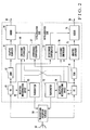
- Fig. 2 shows the receiving side.
- This cross polarized wave interference eliminating system performs microwave communication through two routes by using orthogonal vertically polarized wave (V-polarized wave) and horizontally polarized wave (H-polarized wave). Note that the same reference numerals as in Figs. 7 and 8 denote the same parts in Figs. 1 and 2 .
- components on the V polarization side include a modulator (MOD) 11, variable attenuator (ATT) 12, transmitter (TX) 13, transmission power controller 14, and receiver 15.
- Components on the H polarization side include a modulator (MOD) 21, variable attenuator (ATT) 22, transmitter (TX) 23, transmission power controller 24, and receiver 25.
- a transmission/reception duplexer 31 and antenna 32 are provided as components to be shared by the V polarization wave side and H polarization side.
- the modulators 11 and 21 modulate a V-polarized input baseband signal 10 and H-polarized input baseband signal 20, respectively.
- the variable attenuators 12 and 22 control the output levels of the modulators 11 and 21, respectively.
- the transmitters 13 and 23 respectively convert outputs from the variable attenuators 12 and 22 into signals with predetermined transmission frequencies, and output them as a V-polarized wave and H-polarized wave.
- the transmission/reception duplexer 31 transmits the V- and H-polarized transmission signals from the transmitters 13 and 23 to the opposite station (receiving side) through the antenna 32.
- the transmission/reception duplexer 31 also receives a signal from the opposite station through the antenna 32 and separates it.
- Each of the receivers 15 and 25 demodulates transmission power control information from the opposite station (receiving side) from the signal separated by the transmission/reception duplexer 31.
- the transmission power controllers 14 and 24 respectively control the transmission levels of V- and H-polarized waves by controlling the variable attenuators 12 and 22 on the basis of the demodulated transmission power control information.
- a transmission/reception duplexer 51 and antenna 52 are provided as components to be shared by the V polarization side and H polarization side.
- Components on the V polarization side include receiver (RX) 61, demodulator (DEM) 62, adaptive equalizer 63, adder 64, transmitter 65, reception determination device 66, interference compensator 67, and coefficient controller 68.
- Components on the H polarization side include a receiver (RX) 71, demodulator (DEM) 72, adaptive equalizer 73, adder 74, transmitter 75, reception determination device 76, interference compensator 77, and coefficient controller 78.
- the transmission/reception duplexer 51 receives a signal from an opposite station (transmitting side) through the antenna 52 and separates it.
- the transmission/reception duplexer 51 also sends out signals (transmission power control information) from the transmitters 65 and 75 to the opposite station (transmitting side) through the antenna 52.
- the receivers 61 and 71 convert V- and H-polarized reception signals separated/output from the transmission/reception duplexer 51 into medium-frequency signals.
- the demodulators 62 and 72 demodulate outputs from the receivers 61 and 71 and output the resultant signals.
- the adaptive equalizers 63 and 73 eliminate distortion components on the propagation paths from the outputs from the demodulators 62 and 72.
- the interference compensators 67 and 77 filter the outputs from the receivers 71 and 61 with specific frequency components on the basis of weighting coefficients from the coefficient controllers 68 and 78, and output compensation signals with the same levels as those of interference components and opposite phases thereto.
- the adders 64 and 74 eliminate the cross polarized wave interference components by adding the interference compensation signals generated by the interference compensators 67 and 77 to the output signals from the adaptive equalizers 63 and 73, and output the resultant signals as a V-polarized demodulated baseband signal 60 and H-polarized demodulated baseband signal 70, respectively.
- the reception determination devices 66 and 76 perform determination by comparing the reception levels detected by the receivers 61 and 71 with predetermined threshold levels (thresholds), and output transmission power control information for instructing to increase/decrease the transmitting side power on the basis of the determination results.
- the transmitters 65 and 76 send out the transmission power control information output from the reception determination devices 66 and 7 to the opposite station (transmitting side) through the transmission/reception duplexer 51 and antenna 52.
- the coefficient controllers 68 and 78 generate weighting coefficients to be output to the interference compensators 67 and 77 on the basis of the transmission power control information obtained from both the reception determination devices 66 and 76, and output them.
- the coefficient controllers 68 and 78 and the interference compensators 67 and 77 constitute an interference compensation amount adjusting means.
- the modulators 11 and 21 perform modulation, e.g., quadrature multilevel modulation, of the input baseband signals 10 and 20, and convert them into signals in the medium frequency band. These signals then pass through the variable attenuators 12 and 22 and are converted into signals in the radio frequency band by the transmitters 13 and 23. After the signals pass through the transmission/reception duplexer 31, the signals are transmitted as V- and H-polarized radio outputs from the antenna 32.
- modulation e.g., quadrature multilevel modulation
- the V- and H-polarized components are received by the antenna 52, and then are separated into V- and H-polarized reception signals by the transmission/reception duplexer 51. These signals are amplified by the receivers 61 and 71 and converted into signals in the medium frequency band. The outputs from the receivers 61 and 71 are input to the demodulators 62 and 72, which perform digital determination of the reception signals. The resultant signals are input to the adaptive equalizers 63 and 73, which in turn eliminate the distortion components on the propagation paths. The adders 64 and 74 eliminate cross polarized wave interference components, and output the resultant signals as the demodulated baseband signals 60 and 70.
- the receivers 61 and 71 on the receiving side detect the reception levels of reception signals.
- the reception determination devices 66 and 76 compare the detected signals with specific threshold levels, and generate control signals for increasing or decreasing the power on the transmitting side.
- the transmitters 65 and 75 modulate the control signals to send them out to a radio zone, and transmit the signals for controlling the transmission powers from the antenna 52 through the transmission/reception duplexer 51.
- the signals received by the antenna 32 on the transmitting side are input to the receivers 15 and 25 for V polarization and H polarization through the transmission/reception duplexer 31, which in turn send out the control signals to the transmission power controllers 14 and 24.
- the transmission power controllers 14 and 24 change the attenuation amounts of the variable attenuators 12 and 22 on the transmitting side, on the basis of the signal contents of transmission power control which are received by the transmission power controllers 14 and 24, thereby performing transmission power control operation.
- the signals received by the receivers 61 and 71 on the receiving side are sent out, as reference signals for transmission power interference compensation, to not only the self-polarization (reception signal) side but also the different polarization side.
- the interference compensators 77 and 67 on the different polarization side filter the reference signals with specific frequency components to generate compensation signals with the same levels as those of interference components and opposite phases thereto.
- the adders 64 and 74 add the compensation signals to main signal components. As a consequence, the interference components contained in the main signal components are canceled by the compensation signals to obtain signals without any cross polarized wave interference components.
- the coefficient controllers 68 and 78 control weighting coefficients for tapped transversal filters used in the interference compensators 67 and 77 on the basis of the transmission power control information from the reception determination devices 66 and 76 on the V polarization side and H polarization side.
- the interference compensators 67 and 77 control the normal compensation ranges of the interference compensators 67 and 77 on the basis of the weighting coefficients from the coefficient controllers 68 and 78, thereby adjusting interference compensation amounts.
- the coefficient controllers 68 and 78 control weighting coefficients in accordance with the cross polarized wave interference amounts that can occur when V- and H-polarized waves differ in reception level.
- the interference compensators 67 and 77 then adjust interference compensation amounts on the basis of the weighting coefficients.
- This makes it possible to obtain optimal interference compensation characteristics for cross polarized wave interference when power control is independently performed for each of V- and H-polarized waves.
- this operation requires only relatively small-size hardware, namely the interference compensation amount adjusting means obtained by addition of the coefficient controllers 68 and 78 and slight modifications to the interference compensators 67 and 77.
- transmission power control is to be performed independently by cross polarization, such control can be realized without requiring significant addition of hardware.
- Transmission using cross polarization is the simplest method of independently performing transmission power control for V and H polarization, in consideration of the fact that the above system has many applications of double-polarization transmission as an additional system for an existing system and can be easily added to existing hardware.
- transmission power control for V polarization and that for H polarization need to be linked to each other so as to be simultaneously operated for V and H polarization, and hardware for V polarization and that for H polarization must be designed such that they can operate in cooperation with each other.
- independent transmission power control for V and H polarization can be used without saturation of cross polarized wave interference ability.
- the receiver 61 for V polarization detects a reception level, and sends out a signal indicating a decrease in reception level to the reception determination device 66, and sends out transmission power control information to the transmitter 65 to increase the transmission power on the V polarization side. This notifies the variable attenuator 12 of the signal for changing the attenuation amount through the transmission/reception duplexer 51, antennas 52 and 32, receiver 15, and transmission power controller 14.
- the coefficient controller 68 receives a control signal representing a "decrease” in reception level, i.e., a signal for "increasing” the transmission power, from the reception determination device 66 on the V polarization side.
- the coefficient controller 68 receives a control signal representing reception level "standard”, i.e., a signal for setting the transmission power to "medium”, from the demodulator 76 on the H polarization side.
- the coefficient controllers 68 and 78 include coefficient conversion tables (conversion function), similar to the one shown in Fig. 3 , which control coefficients in accordance with the inputs of the reception determination devices 66 and 76.
- the coefficient controller 68 on the V polarization side sets a weighting coefficient of "1/2" in accordance with an input result indicating that a V-polarized wave (self-polarized wave) is “large”, and an H-polarized wave (different polarized wave) is "medium”.
- the coefficient controller 78 on the H polarization side performs coefficient control to set a weighting coefficient of "2" from an input result indicating that an H-polarized wave (self-polarized wave) is "medium” and a V-polarized wave (different polarized wave) is "large”.
- the interference compensator 67 has a compensation range twice as large as that in the normal case.
- the absolute value of the compensation amount for cross polarized wave interference increases.
- the coefficient controller 78 for V polarization sets a coefficient of "1/2”
- the interference compensator 77 has a compensation range 1/2 that in the normal case. In this case, the coefficient controller 78 decreases the absolute range of compensation amount to a necessary and sufficient range and performs elaborate control within the range.
- coefficient control can be performed in finer steps, on the basis of transmission power control information in finer steps, by using output results of a plurality of bits for address inputs of a plurality of bits using a conversion table such as a ROM.
- Fig. 5 shows the actual arrangement of each of the interference compensators 67 and 77.
- Each of the interference compensators 67 and 77 is comprised of a transversal filter 90 including delay circuits (D) 91 which sequentially delay reception outputs from a corresponding one of the receivers 61 and 71, multipliers 92 which multiply tap outputs from the delay circuits 91 by the tap coefficients generated in a corresponding one of the interference compensators 67 and 77, and a combining circuit 93 which combines outputs from the respective multipliers 92, and weighting circuits 94 which control the respective tap coefficients, on the basis of weighting coefficients (xN) from the coefficient controller 68, by using a bit shift circuit and the like.
- D delay circuits
- the weighting circuits 94 uniformly increase/decrease the respective tap coefficients on the basis of the weighting coefficients from the coefficient controllers 68 and 78 to properly control the interference compensation ranges of the interference compensators 67 and 77, thereby adjusting interference compensation amounts to optimal values.
- a transversal filter with a plurality of taps is a known technique, and hence a detailed description thereof will be omitted.
- Fig. 6 shows another example of the arrangement of each of the interference compensators 67 and 77.
- weighting control on tap coefficients is performed inside the interference compensators 67 and 77 by using weighting coefficients (xN) from the coefficient controllers 68 and 78.
- a weighting circuit 95 is provided on the output stage of the transversal filter 90 to increase/decrease the interference compensation output from the combining circuit 93 in accordance with weighting coefficients from the coefficient controllers 68 and 78.
- the interference compensator outputs are compressed or decompressed to properly control the interference compensation ranges, thereby adjusting interference compensation amounts to optimal values.
- the circuit size can be reduced when the number of taps of a filter is large.
Landscapes
- Engineering & Computer Science (AREA)
- Computer Networks & Wireless Communication (AREA)
- Signal Processing (AREA)
- Radio Transmission System (AREA)
- Mobile Radio Communication Systems (AREA)
- Radio Relay Systems (AREA)
- Variable-Direction Aerials And Aerial Arrays (AREA)
- Cable Transmission Systems, Equalization Of Radio And Reduction Of Echo (AREA)
Abstract
Claims (6)
- Système d'élimination d'interférence d'ondes à polarisation croisée comprenant un moyen, côté récepteur, qui inclut des compensateurs d'interférence (67, 77) qui génèrent des signaux de compensation d'interférence pour compenser respectivement deux composantes à polarisation croisée orthogonales, considérant que le moyen inclut des dispositifs de détermination de réception (66, 76) qui effectuent une détermination en comparant des niveaux de réception détectés par des récepteurs (61, 71) avec des niveaux de seuil prédéterminés pour générer ainsi, pour chaque onde polarisée, des informations de commande de puissance d'émission pour donner comme instruction d'augmenter ou de diminuer la puissance d'un côté émetteur sur la base des résultats de la détermination, et considérant que le moyen est adapté pour notifier les informations au côté émetteur, caractérisé en ce qu'il comprend
un moyen d'ajustement de quantité de compensation d'interférence pour, côté récepteur, ajuster une quantité de compensation d'interférence d'une onde auto-polarisée sur la base des informations de commande de puissance d'émission pour chacune des ondes polarisées. - Système d'élimination d'interférence d'ondes à polarisation croisée selon la revendication 1, caractérisé en ce que ledit moyen d'ajustement de quantité de compensation d'interférence comprend un contrôleur de coefficient (68, 78) qui génère et délivre, sur la base des informations de commande de puissance d'émission pour chacune des ondes polarisées, un coefficient de pondération correspondant à une quantité d'une interférence d'ondes à polarisation croisée se produisant conformément à une différence de niveau de réception entre les deux ondes polarisées, et un compensateur d'interférence (67, 77) qui filtre une sortie de réception sur un côté de polarisation différent avec une composante de fréquence spécifique, et délivre un signal de compensation ayant un niveau correspondant à un coefficient de pondération en provenance dudit contrôleur de coefficient (68, 78) et une phase opposée à une composante d'interférence.
- Système d'élimination d'interférence d'ondes à polarisation croisée selon la revendication 2, caractérisé en ce que ledit compensateur d'interférence (67, 77) inclut un filtre transversal (90) qui filtre une sortie de réception du côté de polarisation différent sur la base d'un coefficient de prise correspondant à une quantité d'interférence d'ondes à polarisation croisée, et un circuit de pondération (95) qui ajuste un niveau d'un signal de compensation délivré par ledit filtre transversal (90) en augmentant/diminuant une valeur du coefficient de prise conformément au coefficient de pondération.
- Système d'élimination d'interférence d'ondes à polarisation croisée selon la revendication 2, caractérisé en ce que ledit compensateur d'interférence (67, 77) inclut un filtre qui filtre une sortie de réception du côté de polarisation différent avec une composante de fréquence spécifique, et un circuit de pondération (95) qui ajuste un niveau d'un signal de compensation délivré par ledit filtre en augmentant/diminuant une sortie dudit filtre sur la base du coefficient de pondération.
- Procédé d'élimination d'interférence d'ondes à polarisation croisée utilisé dans un système d'élimination d'interférence d'ondes à polarisation croisée comprenant les étapes consistant à : générer des signaux de compensation d'interférence par les compensateurs d'interférence (67, 77) pour compenser respectivement deux composantes à polarisation croisée orthogonales, effectuer une détermination par les dispositifs de détermination (66, 76) en comparant des niveaux de réception détectés par les récepteurs (61, 71) avec des niveaux de seuil prédéterminés pour générer ainsi, pour chaque onde polarisée, des informations de commande de puissance d'émission pour donner comme instruction d'augmenter ou de diminuer la puissance d'un côté émetteur sur la base des résultats de la détermination, et notifier les informations au côté émetteur, caractérisé en ce qu'il comprend
l'étape consistant à, côté réception, ajuster une quantité de compensation d'interférence d'une onde auto-polarisée sur la base des informations de commande de puissance d'émission pour chacune des ondes polarisées. - Procédé d'élimination d'interférence d'ondes à polarisation croisée selon la revendication 5, dans lequel l'étape d'ajustement comprend en outre les étapes consistant à :générer, sur la base des informations de commande de puissance d'émission pour chacune des ondes polarisées, un coefficient de pondération correspondant à une quantité d'une interférence d'ondes à polarisation croisée se produisant conformément à une différence de niveau de réception entre les deux ondes polarisées ;filtrer une sortie de réception sur un côté de polarisation différent avec une composante de fréquence spécifique ; etdélivrer un signal de compensation ayant un niveau correspondant au coefficient de pondération et une phase opposée à une composante d'interférence.
Applications Claiming Priority (3)
| Application Number | Priority Date | Filing Date | Title |
|---|---|---|---|
| JP2002104062 | 2002-04-05 | ||
| JP2002104062A JP3925279B2 (ja) | 2002-04-05 | 2002-04-05 | 交差偏波干渉除去システム |
| PCT/JP2003/002924 WO2003085868A1 (fr) | 2002-04-05 | 2003-03-12 | Systeme et procede d'elimination d'interference a polarisation croisee |
Publications (3)
| Publication Number | Publication Date |
|---|---|
| EP1494380A1 EP1494380A1 (fr) | 2005-01-05 |
| EP1494380A4 EP1494380A4 (fr) | 2010-04-14 |
| EP1494380B1 true EP1494380B1 (fr) | 2011-06-15 |
Family
ID=28786326
Family Applications (1)
| Application Number | Title | Priority Date | Filing Date |
|---|---|---|---|
| EP20030710319 Expired - Lifetime EP1494380B1 (fr) | 2002-04-05 | 2003-03-12 | Systeme et procede d'elimination d'interference a polarisation croisee |
Country Status (5)
| Country | Link |
|---|---|
| US (1) | US7206562B2 (fr) |
| EP (1) | EP1494380B1 (fr) |
| JP (1) | JP3925279B2 (fr) |
| NO (1) | NO335765B1 (fr) |
| WO (1) | WO2003085868A1 (fr) |
Cited By (1)
| Publication number | Priority date | Publication date | Assignee | Title |
|---|---|---|---|---|
| US11411617B2 (en) | 2018-05-09 | 2022-08-09 | Sony Group Corporation | Methods and devices for polarization optimization of MIMO wireless transmission |
Families Citing this family (10)
| Publication number | Priority date | Publication date | Assignee | Title |
|---|---|---|---|---|
| US7925236B2 (en) * | 2005-10-20 | 2011-04-12 | Nec Corporation | Cross polarization interference canceling method and cross polarization interference canceling apparatus |
| JP2011097155A (ja) * | 2009-10-27 | 2011-05-12 | Nec Corp | 無線通信システム、および無線通信システムの制御方法 |
| WO2011138971A1 (fr) * | 2010-05-07 | 2011-11-10 | 日本電気株式会社 | Dispositif de transmission, procédé de transmission et système de transmission |
| JP5621341B2 (ja) * | 2010-06-17 | 2014-11-12 | 日本電気株式会社 | 両偏波伝送方式の通信装置及び通信方法 |
| CN102171946B (zh) * | 2011-04-22 | 2013-09-11 | 华为技术有限公司 | 数据传输方法和装置 |
| EP2759108A4 (fr) * | 2011-09-23 | 2015-06-03 | Zte Usa Inc | Câble unique comprenant de multiples interconnexions entre deux unités radios pour annulation de brouillage de polarisation croisée |
| EP2795975B1 (fr) * | 2011-12-22 | 2015-12-16 | Telefonaktiebolaget LM Ericsson (PUBL) | Commande automatique de puissance d'émission dans une configuration xpic pour applications sans fil |
| JP5628237B2 (ja) * | 2012-04-12 | 2014-11-19 | 日本電信電話株式会社 | 可搬型無線通信システムの無線受信装置および干渉抑圧方法 |
| JP6346522B2 (ja) * | 2014-08-25 | 2018-06-20 | 日本放送協会 | 交差偏波干渉除去装置 |
| CN109959909B (zh) * | 2019-03-29 | 2021-04-06 | 北京环境特性研究所 | 用于圆极化测试的单发双收rcs测试系统及测试方法 |
Family Cites Families (12)
| Publication number | Priority date | Publication date | Assignee | Title |
|---|---|---|---|---|
| JPS62186627A (ja) * | 1986-02-12 | 1987-08-15 | Fujitsu Ltd | 交差偏波間干渉補償装置 |
| JPS63272238A (ja) * | 1987-04-30 | 1988-11-09 | Nec Corp | 復調装置 |
| JPH0281528A (ja) * | 1988-09-19 | 1990-03-22 | Nec Corp | 無線通信方式 |
| JP2581200B2 (ja) * | 1988-12-16 | 1997-02-12 | 富士通株式会社 | 送信出力制御方法 |
| JPH03218137A (ja) * | 1990-01-24 | 1991-09-25 | Nec Corp | 受信装置 |
| JPH0425223A (ja) * | 1990-05-18 | 1992-01-29 | Nec Corp | 送信電力制御方式 |
| JP2786008B2 (ja) * | 1990-09-28 | 1998-08-13 | 福島日本電気株式会社 | 無線伝送方式 |
| JP2882147B2 (ja) * | 1991-11-27 | 1999-04-12 | 日本電気株式会社 | 送信電力制御方式 |
| CA2107857C (fr) * | 1992-10-09 | 1998-05-05 | Osamu Kagami | Systeme de relais radio numerique hybride |
| US5818517A (en) * | 1993-11-12 | 1998-10-06 | Northern Telecom Limited | Broadband interference reduction |
| US6356771B1 (en) * | 1998-07-10 | 2002-03-12 | Ericsson, Inc. | Radio communications system with adaptive polarization |
| JP3458834B2 (ja) * | 2000-08-25 | 2003-10-20 | 日本電気株式会社 | 交差偏波干渉除去システム |
-
2002
- 2002-04-05 JP JP2002104062A patent/JP3925279B2/ja not_active Expired - Fee Related
-
2003
- 2003-03-12 EP EP20030710319 patent/EP1494380B1/fr not_active Expired - Lifetime
- 2003-03-12 WO PCT/JP2003/002924 patent/WO2003085868A1/fr not_active Ceased
- 2003-03-12 US US10/509,966 patent/US7206562B2/en not_active Expired - Fee Related
-
2004
- 2004-10-04 NO NO20044190A patent/NO335765B1/no not_active IP Right Cessation
Cited By (1)
| Publication number | Priority date | Publication date | Assignee | Title |
|---|---|---|---|---|
| US11411617B2 (en) | 2018-05-09 | 2022-08-09 | Sony Group Corporation | Methods and devices for polarization optimization of MIMO wireless transmission |
Also Published As
| Publication number | Publication date |
|---|---|
| WO2003085868A1 (fr) | 2003-10-16 |
| US20050163271A1 (en) | 2005-07-28 |
| NO20044190L (no) | 2004-11-04 |
| JP3925279B2 (ja) | 2007-06-06 |
| US7206562B2 (en) | 2007-04-17 |
| EP1494380A4 (fr) | 2010-04-14 |
| NO335765B1 (no) | 2015-02-09 |
| EP1494380A1 (fr) | 2005-01-05 |
| JP2003298546A (ja) | 2003-10-17 |
Similar Documents
| Publication | Publication Date | Title |
|---|---|---|
| JP3565160B2 (ja) | 交差偏波間干渉補償回路 | |
| EP2175572B1 (fr) | Appareil et méthode pour transmision et réception | |
| JP3338747B2 (ja) | 干渉波除去装置 | |
| US10749565B1 (en) | RF front end reduction of receiver de-sensitivity | |
| US20070223617A1 (en) | Multi-port-based mimo antenna receiver | |
| EP1494380B1 (fr) | Systeme et procede d'elimination d'interference a polarisation croisee | |
| EP1233549A2 (fr) | Systeme de Communication | |
| CA2076290A1 (fr) | Recepteur et emetteur radio fonctionnant en diversite | |
| US9083413B2 (en) | Method for reducing interference in a radio network equipment and equipment performing the method | |
| US6937645B2 (en) | Communication system and a receiver for use in the system | |
| WO2016072206A1 (fr) | Système de communications, appareil d'émission et procédé de communications | |
| WO1996008088A1 (fr) | Recepteur en diversite dote d'un melangeur pour l'egalisation et transmetteur en diversite dote d'un diviseur et d'un element de retard | |
| JP3458834B2 (ja) | 交差偏波干渉除去システム | |
| JP2800774B2 (ja) | 交差偏波干渉補償方式 | |
| EP2169844B1 (fr) | Procédé et récepteur de mise en oeuvre de la réutilisation des fréquences dans une communication radio | |
| JPH09233007A (ja) | 無線伝送装置 | |
| JP2004356924A (ja) | アレイアンテナ通信装置 | |
| JPH02246530A (ja) | 多面アンテナsd受信機 | |
| JPH02246528A (ja) | 多面アンテナsd受信機 | |
| JP2004336447A (ja) | アレイアンテナ通信装置 | |
| US8457583B2 (en) | Wireless communication device, wireless communication method, and wireless communication system | |
| CN122001403A (zh) | 自干扰信号消除方法、子带全双工系统及电子设备 | |
| CN118451659A (zh) | Mimo干扰消除 | |
| KR20190103106A (ko) | 페이즈 시프트를 이용한 빔 형성 장치 및 방법 | |
| JP2018011219A (ja) | 受信装置、送信装置、通信システム及び通信方法 |
Legal Events
| Date | Code | Title | Description |
|---|---|---|---|
| PUAI | Public reference made under article 153(3) epc to a published international application that has entered the european phase |
Free format text: ORIGINAL CODE: 0009012 |
|
| 17P | Request for examination filed |
Effective date: 20041007 |
|
| AK | Designated contracting states |
Kind code of ref document: A1 Designated state(s): AT BE BG CH CY CZ DE DK EE ES FI FR GB GR HU IE IT LI LU MC NL PT RO SE SI SK TR |
|
| A4 | Supplementary search report drawn up and despatched |
Effective date: 20100312 |
|
| RIC1 | Information provided on ipc code assigned before grant |
Ipc: H04B 7/10 20060101ALI20100308BHEP Ipc: H04J 11/00 20060101AFI20031018BHEP |
|
| 17Q | First examination report despatched |
Effective date: 20100720 |
|
| GRAP | Despatch of communication of intention to grant a patent |
Free format text: ORIGINAL CODE: EPIDOSNIGR1 |
|
| RIC1 | Information provided on ipc code assigned before grant |
Ipc: H04J 11/00 20060101AFI20101208BHEP Ipc: H04B 7/10 20060101ALI20101208BHEP |
|
| GRAS | Grant fee paid |
Free format text: ORIGINAL CODE: EPIDOSNIGR3 |
|
| GRAA | (expected) grant |
Free format text: ORIGINAL CODE: 0009210 |
|
| AK | Designated contracting states |
Kind code of ref document: B1 Designated state(s): DE GB IT SE |
|
| REG | Reference to a national code |
Ref country code: GB Ref legal event code: FG4D |
|
| REG | Reference to a national code |
Ref country code: DE Ref legal event code: R096 Ref document number: 60337399 Country of ref document: DE Effective date: 20110728 |
|
| REG | Reference to a national code |
Ref country code: SE Ref legal event code: TRGR |
|
| PLBE | No opposition filed within time limit |
Free format text: ORIGINAL CODE: 0009261 |
|
| STAA | Information on the status of an ep patent application or granted ep patent |
Free format text: STATUS: NO OPPOSITION FILED WITHIN TIME LIMIT |
|
| 26N | No opposition filed |
Effective date: 20120316 |
|
| REG | Reference to a national code |
Ref country code: DE Ref legal event code: R097 Ref document number: 60337399 Country of ref document: DE Effective date: 20120316 |
|
| PGFP | Annual fee paid to national office [announced via postgrant information from national office to epo] |
Ref country code: SE Payment date: 20170313 Year of fee payment: 15 Ref country code: DE Payment date: 20170307 Year of fee payment: 15 |
|
| PGFP | Annual fee paid to national office [announced via postgrant information from national office to epo] |
Ref country code: GB Payment date: 20170308 Year of fee payment: 15 |
|
| PGFP | Annual fee paid to national office [announced via postgrant information from national office to epo] |
Ref country code: IT Payment date: 20170320 Year of fee payment: 15 |
|
| REG | Reference to a national code |
Ref country code: DE Ref legal event code: R119 Ref document number: 60337399 Country of ref document: DE |
|
| PG25 | Lapsed in a contracting state [announced via postgrant information from national office to epo] |
Ref country code: SE Free format text: LAPSE BECAUSE OF NON-PAYMENT OF DUE FEES Effective date: 20180313 |
|
| GBPC | Gb: european patent ceased through non-payment of renewal fee |
Effective date: 20180312 |
|
| PG25 | Lapsed in a contracting state [announced via postgrant information from national office to epo] |
Ref country code: DE Free format text: LAPSE BECAUSE OF NON-PAYMENT OF DUE FEES Effective date: 20181002 |
|
| PG25 | Lapsed in a contracting state [announced via postgrant information from national office to epo] |
Ref country code: GB Free format text: LAPSE BECAUSE OF NON-PAYMENT OF DUE FEES Effective date: 20180312 Ref country code: IT Free format text: LAPSE BECAUSE OF NON-PAYMENT OF DUE FEES Effective date: 20180312 |