WO2016084385A1 - Dispositif d'imagerie et véhicule - Google Patents
Dispositif d'imagerie et véhicule Download PDFInfo
- Publication number
- WO2016084385A1 WO2016084385A1 PCT/JP2015/005910 JP2015005910W WO2016084385A1 WO 2016084385 A1 WO2016084385 A1 WO 2016084385A1 JP 2015005910 W JP2015005910 W JP 2015005910W WO 2016084385 A1 WO2016084385 A1 WO 2016084385A1
- Authority
- WO
- WIPO (PCT)
- Prior art keywords
- specific
- image
- filter
- processing unit
- image processing
- Prior art date
- Legal status (The legal status is an assumption and is not a legal conclusion. Google has not performed a legal analysis and makes no representation as to the accuracy of the status listed.)
- Ceased
Links
Images



Classifications
-
- H—ELECTRICITY
- H10—SEMICONDUCTOR DEVICES; ELECTRIC SOLID-STATE DEVICES NOT OTHERWISE PROVIDED FOR
- H10F—INORGANIC SEMICONDUCTOR DEVICES SENSITIVE TO INFRARED RADIATION, LIGHT, ELECTROMAGNETIC RADIATION OF SHORTER WAVELENGTH OR CORPUSCULAR RADIATION
- H10F39/00—Integrated devices, or assemblies of multiple devices, comprising at least one element covered by group H10F30/00, e.g. radiation detectors comprising photodiode arrays
- H10F39/80—Constructional details of image sensors
- H10F39/805—Coatings
- H10F39/8053—Colour filters
-
- G—PHYSICS
- G02—OPTICS
- G02B—OPTICAL ELEMENTS, SYSTEMS OR APPARATUS
- G02B5/00—Optical elements other than lenses
- G02B5/20—Filters
-
- G—PHYSICS
- G06—COMPUTING OR CALCULATING; COUNTING
- G06V—IMAGE OR VIDEO RECOGNITION OR UNDERSTANDING
- G06V20/00—Scenes; Scene-specific elements
- G06V20/50—Context or environment of the image
- G06V20/56—Context or environment of the image exterior to a vehicle by using sensors mounted on the vehicle
- G06V20/58—Recognition of moving objects or obstacles, e.g. vehicles or pedestrians; Recognition of traffic objects, e.g. traffic signs, traffic lights or roads
-
- H—ELECTRICITY
- H04—ELECTRIC COMMUNICATION TECHNIQUE
- H04N—PICTORIAL COMMUNICATION, e.g. TELEVISION
- H04N23/00—Cameras or camera modules comprising electronic image sensors; Control thereof
- H04N23/10—Cameras or camera modules comprising electronic image sensors; Control thereof for generating image signals from different wavelengths
- H04N23/12—Cameras or camera modules comprising electronic image sensors; Control thereof for generating image signals from different wavelengths with one sensor only
-
- H—ELECTRICITY
- H04—ELECTRIC COMMUNICATION TECHNIQUE
- H04N—PICTORIAL COMMUNICATION, e.g. TELEVISION
- H04N25/00—Circuitry of solid-state image sensors [SSIS]; Control thereof
- H04N25/10—Circuitry of solid-state image sensors [SSIS]; Control thereof for transforming different wavelengths into image signals
- H04N25/11—Arrangement of colour filter arrays [CFA]; Filter mosaics
- H04N25/13—Arrangement of colour filter arrays [CFA]; Filter mosaics characterised by the spectral characteristics of the filter elements
- H04N25/135—Arrangement of colour filter arrays [CFA]; Filter mosaics characterised by the spectral characteristics of the filter elements based on four or more different wavelength filter elements
-
- H—ELECTRICITY
- H04—ELECTRIC COMMUNICATION TECHNIQUE
- H04N—PICTORIAL COMMUNICATION, e.g. TELEVISION
- H04N7/00—Television systems
- H04N7/18—Closed-circuit television [CCTV] systems, i.e. systems in which the video signal is not broadcast
-
- H—ELECTRICITY
- H10—SEMICONDUCTOR DEVICES; ELECTRIC SOLID-STATE DEVICES NOT OTHERWISE PROVIDED FOR
- H10F—INORGANIC SEMICONDUCTOR DEVICES SENSITIVE TO INFRARED RADIATION, LIGHT, ELECTROMAGNETIC RADIATION OF SHORTER WAVELENGTH OR CORPUSCULAR RADIATION
- H10F39/00—Integrated devices, or assemblies of multiple devices, comprising at least one element covered by group H10F30/00, e.g. radiation detectors comprising photodiode arrays
- H10F39/10—Integrated devices
- H10F39/12—Image sensors
- H10F39/18—Complementary metal-oxide-semiconductor [CMOS] image sensors; Photodiode array image sensors
- H10F39/182—Colour image sensors
-
- B—PERFORMING OPERATIONS; TRANSPORTING
- B60—VEHICLES IN GENERAL
- B60R—VEHICLES, VEHICLE FITTINGS, OR VEHICLE PARTS, NOT OTHERWISE PROVIDED FOR
- B60R2300/00—Details of viewing arrangements using cameras and displays, specially adapted for use in a vehicle
- B60R2300/10—Details of viewing arrangements using cameras and displays, specially adapted for use in a vehicle characterised by the type of camera system used
-
- B—PERFORMING OPERATIONS; TRANSPORTING
- B60—VEHICLES IN GENERAL
- B60R—VEHICLES, VEHICLE FITTINGS, OR VEHICLE PARTS, NOT OTHERWISE PROVIDED FOR
- B60R2300/00—Details of viewing arrangements using cameras and displays, specially adapted for use in a vehicle
- B60R2300/80—Details of viewing arrangements using cameras and displays, specially adapted for use in a vehicle characterised by the intended use of the viewing arrangement
- B60R2300/8093—Details of viewing arrangements using cameras and displays, specially adapted for use in a vehicle characterised by the intended use of the viewing arrangement for obstacle warning
Definitions
- the present invention relates to an imaging device and a vehicle.
- an image capturing apparatus In order to obtain functions other than color image capturing, an image capturing apparatus has been proposed in which a filter in a specific wavelength region is arranged in part of a color filter array in an image sensor. For example, it has been proposed that a filter having a wavelength region suitable for imaging an iris is arranged in an imaging element, and that imaging is performed only with pixels on which the filter is arranged when imaging an iris (see Patent Document 1).
- An object of the present invention is to provide an imaging device and a vehicle that can exhibit a specific function depending on the application.
- An imaging apparatus includes: Corresponding to each pixel, at least one type of color filter and a specific filter that transmits a specific wavelength range in which the spectral irradiance of sunlight is lower than the wavelength range adjacent to both sides are arranged on the light receiving surface.
- An image sensor Based on a signal component generated by a pixel in which the specific filter is arranged in an image signal acquired from the image sensor, an irradiation state of a specific light source different from sunlight irradiated to the imaging range of the image sensor is detected.
- An image processing unit Based on a signal component generated by a pixel in which the specific filter is arranged in an image signal acquired from the image sensor, an irradiation state of a specific light source different from sunlight irradiated to the imaging range of the image sensor is detected.
- an imaging apparatus includes: Corresponding to each pixel, at least one type of color filter and a specific filter that transmits a specific wavelength range in which the spectral irradiance of sunlight is lower than the wavelength range adjacent to both sides are arranged on the light receiving surface.
- An image sensor It is determined whether or not the brightness of the first captured image by a pixel in which at least the color filter of the image sensor is disposed is less than a predetermined reference, and the brightness of the first captured image is greater than or equal to a predetermined reference.
- An image processing unit that, when determined, acquires a second captured image using only the pixels on which the specific filter is arranged.
- a vehicle is Corresponding to each pixel, at least one type of color filter and a specific filter that transmits a specific wavelength range in which the spectral irradiance of sunlight is lower than the wavelength range adjacent to both sides are arranged on the light receiving surface. Based on a signal component of an image sensor and a pixel in which the specific filter is arranged in an image signal acquired from the image sensor, an irradiation state of a specific light source other than sunlight irradiated on an imaging range of the image sensor An imaging apparatus having an image processing unit to detect and the specific light source.
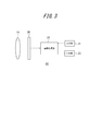
- FIG. 3 is a layout diagram illustrating various device layouts in the vehicle including the imaging device according to the first embodiment of the present invention. It is a spectral emission spectrum of sunlight. It is a functional block diagram which shows schematic structure of the imaging device of FIG.
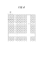
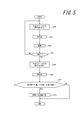
- FIG. 4 is an array diagram showing a filter array of color filters covering a light receiving surface of the image sensor of FIG. 3. It is a flowchart for demonstrating the abnormality detection process of the specific light source which the image process part of FIG. 3 performs.
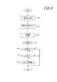
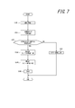
- FIG. 4 is a flowchart for explaining a process for determining whether or not a subsequent object is irradiated with light, which is executed by the image processing unit of FIG. 3. It is a flowchart for demonstrating the specific image process which the image process part of FIG.
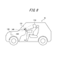
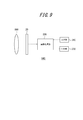
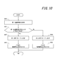
- FIG. 5 is a layout diagram illustrating various device layouts in a vehicle including an imaging device according to a second embodiment of the present invention. It is a functional block diagram which shows schematic structure of the imaging device of FIG. It is a flowchart for demonstrating the operation mode determination process which the image process part of FIG. 8 performs. It is a flowchart for demonstrating the operation
- FIG. 1 is a schematic side view showing the arrangement of the imaging device according to the first embodiment of the present invention on a vehicle (moving body).
- the vehicle 10 includes a display unit 11, a lamp ECU 12, a specific light source 13, and an imaging device 14.
- the imaging device 14, the display unit 11, and the lamp ECU 12 can transmit information and signals via a dedicated line or a vehicle-mounted network such as CAN.
- the lamp ECU 12 and the specific light source 13 can transmit information and signals via a dedicated line or an in-vehicle network such as CAN.
- the display unit 11 is provided at a position where the driver can visually recognize it.
- the lamp ECU 12 is provided at an arbitrary position of the vehicle 10.
- the specific light source 13 includes, for example, a tail lamp 15, a brake lamp 16, a backup lamp 17, and a direction indication lamp 18, and is provided behind the vehicle 10.
- the imaging device 14 is provided at the rear of the vehicle 10 so that a subject outside the vehicle 10 can be imaged, for example, a subject outside the vehicle 10 can be imaged.
- the display unit 11 is a liquid crystal display, for example, and displays various images. In the present embodiment, the display unit 11 displays an image corresponding to an image signal acquired from the imaging device 14.
- the lamp ECU 12 drives various types of lamps of the vehicle 10 in response to an operation input by the driver.
- the lamp ECU 12 turns on the tail lamp 15 when, for example, the driver inputs an operation to turn on the lamp switch.
- the lamp ECU 12 turns on the brake lamp 16 when the driver inputs an operation to step on the brake pedal.
- the lamp ECU 12 lights the backup lamp 17 when performing an operation input to place the shift lever in the reverse position.
- the lamp ECU 12 turns on the direction indicator lamp 18 when the driver performs an operation input for rotating the winker lever in any direction.
- the lamp ECU 12 transmits information indicating that the tail lamp 15, the brake lamp 16, the backup lamp 17, and the direction indicator lamp 18 are lit to the imaging device 14. Further, the lamp ECU 12 adjusts the light amount and the irradiation direction of the tail lamp 15 based on information on the subsequent vehicle acquired from the imaging device 14 as will be described later.
- the tail lamp 15, the brake lamp 16, the backup lamp 17, and the direction indicator lamp 18 are turned on and off based on the control of the lamp ECU 12.
- the tail lamp 15, the brake lamp 16, the backup lamp 17, and the direction indicator lamp 18 have, for example, an incandescent bulb as a light source, and have a specific wavelength in which the spectral irradiance is lower than the wavelength range adjacent to both sides in the solar radiation spectrum. It emits light that includes at least light in the region. As shown in FIG.
- the specific wavelength range is, for example, a wavelength range of 320 nm or less absorbed by O 3 , a wavelength range of 750 nm to 760 nm absorbed by H 2 O or O 2 , and a wavelength range of 930 nm to 970 nm.
- the wavelength range is 1100 nm or more and 1170 nm or less.
- the imaging device 14 images a subject.
- the imaging device 14 detects the irradiation state of the specific light source 13 based on the captured subject. Further, the imaging device 14 performs predetermined image processing on the captured image of the subject and outputs the processed image to the display unit 11.
- the above-described functions of the imaging device 14 will be described in detail together with the configuration of the imaging device 14.
- the imaging device 14 includes an optical system 19, an imaging element 20, an input unit 21, an image processing unit 22, and an output unit 23.
- the optical system 19 is composed of an optical element including at least one lens so as to have desired optical characteristics such as a focal length, a focal depth, and an angle of view.
- the optical system 19 forms a subject image on the image sensor 20.
- the image pickup device 20 is, for example, a CMOS image pickup device or a CCD image pickup device, and picks up an image of a subject formed on the light receiving surface to generate an image signal.
- a plurality of pixels are two-dimensionally arranged on the light receiving surface of the image sensor 20, and each pixel generates a pixel signal corresponding to the amount of received light.
- One frame of the image signal is composed of pixel signals generated by each pixel constituting the light receiving surface.
- Each pixel is covered with at least one color filter or a specific filter.
- the at least one color filter is, for example, an R filter, a G filter, and a B filter.
- the at least one color filter may be another visible light range filter.
- the specific filter has the above-described specific wavelength region included in the light emitted from the above-described specific light source 13 as a transmission region.
- each of the R filter (see the reference “R”), the G filter (see the reference “G”), the B filter (see the reference “B”), and the specific filter (see the reference “S”) is 1 each.
- Each unit array UA is periodically arranged in a two-dimensional manner.
- the arrangement of the filters is not limited to such an arrangement.
- the unit array UA including a specific filter may be arranged so as to be replaced in a part in the row direction and the column direction of the Bayer array.
- the input unit 21 acquires information indicating that the tail lamp 15, the brake lamp 16, the backup lamp 17, and the direction indicator lamp 18 are lit from the lamp ECU 12.
- the image processing unit 22 is a general-purpose CPU that executes a specific function by reading a DSP or a specific program, for example.
- the image processing unit 22 acquires an image signal from the image sensor 20.
- the image processing unit 22 performs pre-processing such as white balance processing and color interpolation processing on the image signal.
- the image processing unit 22 further performs subsequent processing such as contour enhancement processing on the image signal that has been subjected to the previous processing.
- the image processing unit 22 detects an irradiation state of a specific light source 13 that is irradiated to an image signal, that is, an imaging range of the imaging element. Further, as will be described later, the image processing unit 22 performs specific image processing on the image signal that has been subjected to the previous stage processing, including the subsequent stage processing.
- the output unit 23 outputs an image signal on which the image processing unit 22 has undergone predetermined image processing including pre-processing and post-processing to the display unit 11.
- the output unit 23 outputs information generated by the image processing unit 22 based on the detection of the irradiation state of the specific light source 13 to at least one of the display unit 11 and the lamp ECU 12.
- the detection of the irradiation state of the specific light source 13 includes detection of the actual irradiation state of the specific light source 13, that is, detection of an abnormality of the specific light source 13, and determination of the presence or absence of light irradiation to the subsequent object. , Explain separately.
- the image processing unit 22 detects an abnormality of the specific light source 13 when acquiring information indicating that the specific light source 13 is lit from the lamp ECU 12.
- the image processing unit 22 extracts a signal component corresponding to a light amount in a specific wavelength region, for example, a signal component generated by a pixel in which a specific filter is arranged, from an image signal acquired from the image sensor 20.
- the pixels from which the signal component is extracted may be all the pixels constituting the image, or may be a pixel in a region assumed to be irradiated with light emitted from the specific light source 13.
- the image processing unit 22 determines that the specific light source 13 is normal when the signal intensity of the extracted signal component, that is, the actual irradiation light amount of the specific light source 13 is sufficiently large, and the specific intensity when the signal intensity is low. It is determined that an abnormality has occurred in the light source 13. Specifically, the image processing unit 22 compares the signal components of the pixels in which the specific filter is disposed when the specific light source 13 is turned on and off, for example, by comparing the ratio between the two with a threshold value. 13 abnormality determination is performed.
- the image processing unit 22 compares, for example, the average value of the signal strengths of the extracted signal components with a threshold value, and is normal when the average value exceeds the threshold value, and an abnormality occurs when the average value is equal to or less than the threshold value. It may be determined that
- the image processing unit 22 determines that an abnormality has occurred in the specific light source 13, an image for notifying that there is an abnormality in the specific light source 13, for example, an image in which a message is superimposed on an image acquired from the image sensor 20. Is generated.
- the image processing unit 22 outputs the notification image to the display unit 11 via the output unit 23 and causes the display unit 11 to display the image.
- the image processing unit 22 determines whether or not a subsequent object, for example, a vehicle, is irradiated with light when acquiring information indicating that the tail lamp 15 is lit, for example, in a specific light source 13 from the lamp ECU 12. .
- the image processing unit 22 includes a signal component corresponding to the light amount in a specific wavelength region, for example, a specific filter, in the image signal acquired from the image sensor 20. The signal component generated by the selected pixel is extracted.
- the image processing unit 22 extracts a signal component whose signal intensity exceeds a threshold value from the extracted signal components, and calculates position coordinates in the entire image of the corresponding pixel.
- the image processing unit 22 performs known object recognition on the entire image and detects other vehicles.
- the image processing unit 22 determines whether or not the detected area occupied by the vehicle overlaps with the calculated position coordinates.
- the image processing unit 22 changes the irradiation direction of the light from the tail lamp 15 vertically downward. A command to decrease or a command to decrease the amount of light is generated.
- the image processing unit 22 outputs the command to the lamp ECU 12 via the output unit 23, and adjusts at least one of the irradiation direction of the light from the tail lamp 15 and the light amount.
- the image processing unit 22 performs specific image processing from the lamp ECU 12 when, for example, information indicating that the backup lamp 17 is lit in the specific light source 13 is acquired. First, the image processing unit 22 extracts pixels whose luminance based on signal components other than a specific wavelength range, for example, RGB signal components, exceeds a threshold value. Next, the image processing unit 22 determines whether or not an area exceeding a predetermined size (a predetermined number of pixels) is formed by the extracted pixels.
- a predetermined size a predetermined number of pixels
- the image processing unit 22 generates a signal component in a specific wavelength region, that is, a pixel in which a specific filter is arranged, without using the RGB signal component for a pixel forming a region exceeding a predetermined size.
- a monochrome image is created using only signal components.
- the image processing unit 22 creates a color image in the same manner as usual in other pixels, and generates an image obtained by combining the color image and the monochrome image as an image signal.
- the image processing unit 22 outputs the image signal to the display unit 11 via the output unit 23 and causes the display unit 11 to display the image signal.
- the image processing unit 22 starts an abnormality detection process for the specific light source 13 when acquiring information indicating that the specific light source 13 is lit from the lamp ECU 12.
- step S100 the image processing unit 22 extracts a signal component corresponding to the amount of light in a specific wavelength region from the image signal. Once the signal component is extracted, the process proceeds to step S101.
- step S101 the image processing unit 22 averages the signal strength of the signal component extracted in step S100.
- the image processing unit 22 converts the averaged signal strength to the averaged signal in the image signal of the previous frame. Average with intensity.
- the process proceeds to step S102.
- step S102 the image processing unit 22 stores the signal intensity averaged in step S102 in a memory included in the image processing unit 22. Once stored in memory, the process proceeds to step S103.
- step S103 the image processing unit 22 determines whether or not information for turning off the specific light source 13 is acquired from the lamp ECU 12. When the information to turn off is not acquired, the process returns to step S100. When the information to be turned off is acquired, the process proceeds to step S104.
- step S104 the image processing unit 22 extracts a signal component corresponding to the amount of light in a specific wavelength region from the image signal. Once the signal component is extracted, the process proceeds to step S105.
- step S105 the image processing unit 22 averages the signal strength of the signal component extracted in step S104.
- the process proceeds to step S106.
- step 106 the image processing unit 22 compares the threshold value with the ratio obtained by dividing the average value of the signal intensity at the time of lighting stored in the memory in step S102 by the average value of the signal intensity at the time of extinction calculated in step S105. To do. If the ratio is greater than or equal to the threshold, step S107 is skipped, and the process for detecting a specific light source 13 is completed. If the ratio is less than the threshold, the process proceeds to step S107.
- step S107 the image processing unit 22 generates an image notifying that the specific light source 13 is abnormal. Further, the image processing unit 22 outputs the image to the display unit 11 via the output unit 23. After outputting the image, the abnormality detection process for the specific light source 13 is terminated.
- the image processing unit 22 acquires information indicating that the specific light source 13 is lit from the lamp ECU 12, the image processing unit 22 starts a process for determining whether or not the subsequent object is irradiated with light.
- step S200 the image processing unit 22 extracts a signal component corresponding to the amount of light in a specific wavelength region from the image signal. Once the signal component is extracted, the process proceeds to step S201.
- step S201 the image processing unit 22 further extracts signal components that exceed the threshold from the signal components extracted in step S200. If more signal components are extracted, the process proceeds to step S202.
- step S202 the image processing unit 22 calculates the position coordinates of the pixel corresponding to the signal component extracted in step S201. After calculating the position coordinates, the process proceeds to step S203.
- step S203 the image processing unit 22 performs object recognition on the entire image. After object recognition, the process proceeds to step S204.
- step S204 the image processing unit 22 determines whether or not a vehicle is included in the image by the object recognition executed in step S203. If a vehicle is included, the process proceeds to step S205. When the vehicle is not included, the process for determining whether or not the subsequent object is irradiated with light ends.
- step S205 the image processing unit 22 determines whether or not the area occupied by the vehicle overlaps the position coordinates of the pixel calculated in step S202. If so, the process proceeds to step S206. If they do not overlap, the process for determining whether or not the subsequent object is irradiated with light ends.
- step S206 the image processing unit 22 generates a command for lowering the irradiation direction of light from the tail lamp 15 vertically or a command for reducing the amount of light. Further, the image processing unit 22 outputs the command to the lamp ECU 12 via the output unit 23. After the output of the command, the process for determining whether or not the subsequent object is irradiated with light is terminated.
- the image processing unit 22 starts specific image processing when acquiring information indicating that the specific light source 13 is lit from the lamp ECU 12.
- step S300 the image processing unit 22 calculates the luminance in each pixel using the RGB signal components. When the luminance of all pixels is calculated, the process proceeds to step S301.
- step S301 the image processing unit 22 extracts pixels whose luminance exceeds a threshold value from the image signal. Once the pixel is extracted, the process proceeds to step S302.
- step S302 the image processing unit 22 determines whether or not the pixel extracted in step S301 forms an area exceeding a predetermined size. When the area exceeding the predetermined size is not formed, the process proceeds to step S303. When forming an area exceeding the predetermined size, the process proceeds to step S304.
- step S303 the image processing unit 22 generates a color image using only the RGB signal components for the entire area of the image signal.
- the image processing unit 22 performs subsequent processing on the generated color image and outputs the processed color image to the display unit 11. After outputting the color image, the specific image processing is terminated.
- step S304 the image processing unit 22 generates a monochrome image using only a signal component in a specific wavelength region within the region determined in step S302 of the image signal. After the monochrome image is generated, the process proceeds to step S305.
- step S305 the image processing unit 22 generates a color image using only the RGB signal component outside the region determined in step S302 of the image signal. After generation of the color image, the process proceeds to step S306.
- step S306 the image processing unit 22 combines the monochrome image generated in step S304 and the color image generated in step S305.
- the image processing unit 22 performs subsequent processing on the combined image and outputs the processed image to the display unit 11. After outputting the combined image, the specific image processing is terminated.
- the irradiation state of the specific light source 13 is detected based on the signal component of the pixel in which the specific filter is arranged. Therefore, it is possible to detect the irradiation state of the specific light source 13 that is difficult for the naked eye even outdoors where sunlight is sufficiently irradiated. Therefore, the irradiation state of the specific light source 13 is detected when the subject is brightly illuminated by sunlight according to the use of imaging a subject that may be irradiated with light from the specific light source 13 like the vehicle 10. It can perform a specific function.
- the imaging apparatus 14 since the imaging apparatus 14 includes the input unit 21, processing using pixels in which a specific filter is arranged (abnormality detection processing of a specific light source 13, and subsequent object detection) A start condition can be given to the determination processing of the presence or absence of light emission, specific image processing). By giving the start condition, unnecessary execution of processing using a pixel in which a specific filter is arranged can be suppressed, and as a result, power consumption can be reduced.
- the imaging device of this embodiment when irradiating light from the specific light source 13, the actual irradiation state of the specific light source 13 based on the signal component of the pixel in which the specific filter is arranged. In other words, the presence or absence of an abnormality is detected. Therefore, even in a bright environment such as the daytime, the abnormality of the specific light source 13 can be detected using a specific image that is difficult to visually recognize in the color image.
- the imaging device of this embodiment when irradiating light from a specific light source 13, it is determined whether or not the subsequent vehicle is irradiated with the light, and the irradiation direction or the like is determined when irradiating. Since the adjustment is performed, glare that can be perceived by the occupant of the following vehicle can be suppressed.
- an image is generated using the signal component generated by the pixel in which the specific filter is disposed. Is generated. Therefore, for example, in the case of an image captured in the tunnel, even when a subject outside the tunnel is blown out due to exposure adjustment for a dark place, the brightness of sunlight is suppressed while the specific light source 13 is used. Since light in a specific wavelength range is appropriately irradiated, a subject outside the tunnel can be reproduced in a visible manner.
- the vehicle 10 includes a lamp ECU 120, a specific light source 130, and an imaging device 140.
- the imaging device 140 and the lamp ECU 120 can transmit information and signals via a dedicated line or an in-vehicle network such as CAN.
- both the lamp ECU 120 and the light source 130 can transmit information and signals via a dedicated line or an in-vehicle network such as CAN.
- the lamp ECU 120 is provided at an arbitrary position of the vehicle 10.
- the light source 130 is disposed on the dashboard 240 of the vehicle 10, for example, and can irradiate light on the face of the subject 250 such as a driver. As will be described later, the light source 130 emits light in a specific wavelength range.
- the imaging device 140 is disposed on the dashboard 240 of the vehicle 10, for example, and can capture the face of the subject 250 irradiated with light from the light source 130. Specifically, the imaging device 140 is arranged on the vehicle 10 so that the field of view of the imaging device 140 includes a relatively wide area where the face of the subject 250 can exist in the vehicle 10.
- the lamp ECU 120 turns on the light source 130 based on information acquired from the imaging device 140 as described later.
- the lamp ECU 120 turns on the light source 130 in synchronization with the imaging timing of the imaging device 140 based on a synchronization signal acquired from the imaging device 140 as described later.
- the lamp ECU 120 keeps the light source 130 off when the imaging device 140 operates in the first operation mode as will be described later, and the light source 130 when the imaging device 140 operates in the second operation mode. 130 is turned on.
- the lamp ECU 120 may transmit information indicating that the light source 130 is lit to the imaging device 140 as in the first embodiment described above.
- the light source 130 is, for example, an LED, and emits light in a predetermined wavelength band.
- the light source 130 has a wavelength range of 320 nm or less absorbed by O 3 , a wavelength range of 750 nm to 760 nm absorbed by H 2 O or O 2 , a wavelength range of 930 nm to 970 nm, or 1100 nm or more. It is a lamp that emits light in a wavelength range of 1170 nm or less.
- the light source 130 may include, for example, an illumination optical system including a lens whose angle of view is adjusted. Any wavelength range and directivity of emitted light can be employed.
- the light source 130 is an infrared lamp that emits light in a wavelength range of 750 nm to 760 nm, a wavelength range of 930 nm to 970 nm, or a wavelength range of 1100 nm to 1170 nm in the infrared band.
- the imaging device 140 captures the face of the subject 250 and generates a captured image. Moreover, the imaging device 140 determines the state of the subject 250 based on the captured image. Preferably, the imaging device 140 issues a warning to the subject 250 when it is determined that the subject 250 is in a specific state.
- the above-described functions of the imaging device 140 will be described in detail together with the configuration of the imaging device 14.
- the imaging device 140 includes an optical system 190, the imaging device 20, an input unit 210, an image processing unit 220, and an output unit 230.
- the optical system 190 includes an optical element including at least one lens so as to have desired optical characteristics such as a focal length, a focal depth, and an angle of view.
- the optical system 190 forms a subject image on the image sensor 20.
- the imaging optical system 190 is disposed in the housing of the imaging device 140 so that reflected light from the irradiation destination of the illumination light from the light source 130 can be captured.
- the optical system 190 can form an image of a subject including the face of the subject 250 irradiated with illumination light.
- the input unit 210 acquires information that the light source 130 is lit from the lamp ECU 120 when the image processing unit 220 operates in the second operation mode as described later.
- the image processing unit 220 is a general-purpose CPU that executes a specific function by reading a DSP or a specific program, for example.
- the image processing unit 220 performs various image processing on an image signal (hereinafter also referred to as “captured image”) generated by the image sensor 20 and controls the operation of the entire image capturing apparatus 140.
- the image processing unit 220 generates a synchronization signal indicating the timing of imaging and outputs the synchronization signal to the lamp ECU 120 via the output unit 230.
- the image processing unit 220 controls the operation of the image sensor 20 to periodically image a subject at, for example, 60 fps.
- the image processing unit 220 operates in the first operation mode or the second operation mode as described later.
- the image processing unit 220 acquires a captured image (first captured image) from the image sensor 20.
- the first picked-up image is a picked-up image at least with pixels in which color filters are arranged, for example, a color image.
- the image processing unit 220 performs first pre-stage processing such as exposure adjustment processing, white balance processing, and color interpolation processing on the first captured image.
- the image processing unit 220 further performs subsequent processing such as contour enhancement processing on the first captured image that has been subjected to the first previous processing.
- the image processing unit 220 determines whether or not the brightness of the first captured image that has been subjected to the first pre-stage process and the post-stage process is less than a predetermined reference.
- the predetermined reference brightness is a brightness at which the detection accuracy of the face of the target person 250 on the first captured image is reduced to a certain degree in an object detection process described later, for example, the first captured image is whiteout.
- the image processing unit 220 determines the brightness of the first captured image when the signal intensity of the extracted signal component, that is, the amount of sunlight irradiated into the vehicle 10 as external light is less than a predetermined threshold. Is determined to be less than the standard.
- the predetermined threshold value can be determined in advance by, for example, experiments or simulations.
- the image processing unit 220 When it is determined that the signal intensity of the extracted signal component is less than a predetermined threshold, that is, when it is determined that the brightness of the first captured image is less than a predetermined reference, the image processing unit 220 The operation mode is determined as the first operation mode. In addition, the image processing unit 220 outputs a drive stop request for the light source 130 to the lamp ECU 120 via the output unit 230. The lamp ECU 120 that has acquired the action stop request keeps the light source 130 off.
- the image processing unit 220 determines whether the signal intensity of the extracted signal component is equal to or higher than the predetermined threshold, that is, when it is determined that the brightness of the first captured image is equal to or higher than the predetermined reference.
- the image processing unit 220 determines the operation mode to be the second operation mode. Further, the image processing unit 220 outputs a drive start request for the light source 130 to the lamp ECU 120 via the output unit 230.
- the lamp ECU 120 that has acquired the drive start request starts lighting the light source 130 based on the above-described synchronization signal.
- the image processing unit 220 acquires a captured image from the image sensor 20. Subsequently, the image processing unit 220 performs first pre-processing such as exposure adjustment processing, white balance processing, and color interpolation processing on the captured image. The image processing unit 220 further performs subsequent processing such as edge enhancement processing on the captured image that has been subjected to the first previous processing.
- first pre-processing such as exposure adjustment processing, white balance processing, and color interpolation processing
- the image processing unit 220 further performs subsequent processing such as edge enhancement processing on the captured image that has been subjected to the first previous processing.
- subsequent processing such as edge enhancement processing on the captured image that has been subjected to the first previous processing.
- the first captured image the first captured image generated in the operation mode determination process described above may be used.
- the image processing unit 220 executes an object detection process using the first captured image that is a color image.
- the object detection processing for example, any method such as a method using pattern matching or a method for extracting feature points on a captured image can be adopted.
- an algorithm corresponding to a color image for example, an algorithm corresponding to a color image may be used.
- the object detection process detects the face, eyes, and pupils of the subject 250 (hereinafter also simply referred to as “the face of the subject 250”).
- the image processing unit 220 issues a warning to the subject person 250 based on the detection result of the subject person 250 on the first captured image. For example, when the eye or pupil of the subject 250 on the first captured image cannot be detected continuously for a predetermined time (over a predetermined number of frames), the subject 250 performs a look-ahead driving or a dozing operation. The probability of being in a state (specific state) is high. When it is determined that the target person 250 is in the specific state, the image processing unit 220 issues a warning.
- the execution of the warning includes, for example, generation of a warning sound through a speaker provided in the imaging device 140 or output of a warning signal for generating a warning sound through a speaker provided in the vehicle 10.
- the image processing unit 220 acquires a first captured image from the image sensor 20. Subsequently, the image processing unit 220 extracts only the pixel signal generated by the pixel in which the specific filter is arranged from the first captured image acquired from the image sensor 20, and acquires the second captured image.
- the second captured image is, for example, a monochrome image. Subsequently, the image processing unit 220 performs second pre-processing such as exposure adjustment processing on the second captured image. The image processing unit 220 further performs subsequent processing such as contour enhancement processing on the second captured image that has been subjected to the second previous processing.
- the image processing unit 220 executes object detection processing using the second captured image that is a monochrome image.
- object detection processing for example, any method such as a method using pattern matching or a method for extracting feature points on a captured image can be adopted.
- an algorithm corresponding to a monochrome image may be used.
- the object detection process detects the face, eyes, and pupils of the subject 250 (hereinafter also simply referred to as “the face of the subject 250”).
- the image processing unit 220 issues a warning to the target person 250 based on the detection result of the target person 250 on the second captured image. For example, when the eye or pupil of the subject 250 on the second captured image cannot be detected continuously for a predetermined time (over a predetermined number of frames), the subject 250 performs a look-ahead driving or a dozing operation. The probability of being in a state (specific state) is high. When it is determined that the target person 250 is in the specific state, the image processing unit 220 issues a warning.
- the execution of the warning includes, for example, generation of a warning sound through a speaker provided in the imaging device 140 or output of a warning signal for generating a warning sound through a speaker provided in the vehicle 10.
- the algorithm for determining the state of the subject 250 in the second operation mode may be different from the algorithm for determining the state of the subject 250 in the first operation mode described above.
- the image processing unit 220 may detect the abnormality of the light source 130 in the same manner as in the first embodiment described above during execution of the operation in the second operation mode.
- the output unit 230 outputs a drive stop request and a drive start request for the light source 130 generated by the image processing unit 220 to the lamp ECU 120.
- the output unit 230 outputs the warning signal generated by the image processing unit 220 to, for example, an ECU provided in the vehicle 10.
- the operation mode determination process may be executed in each frame in which the image sensor 20 generates a captured image, or may be executed intermittently in some frames.
- step S400 the image processing unit 220 acquires a first captured image from the image sensor 20.
- the image processing unit 220 performs first pre-processing and post-processing on the first captured image. Thereafter, the process proceeds to step S401.
- step S401 the image processing unit 220 determines whether or not the brightness of the first captured image is less than a predetermined reference. If it is determined that the brightness is less than the reference, the process proceeds to step S402. On the other hand, if it is determined that the brightness is above the reference, the process proceeds to step S404.
- step S402 the image processing unit 220 determines the operation mode as the first operation mode. Thereafter, the process proceeds to step S403.
- step S403 the image processing unit 220 outputs a drive stop request for the light source 130 to the lamp ECU 120 via the output unit 230, and ends the operation mode determination process.
- step S404 the image processing unit 220 determines the operation mode to be the second operation mode. Thereafter, the process proceeds to step S405.
- step S ⁇ b> 405 the image processing unit 220 outputs a drive start request for the light source 130 to the lamp ECU 120 via the output unit 230. Thereafter, the operation mode determination process ends.
- step S500 the image processing unit 220 acquires a captured image. Specifically, in the first operation mode, the image processing unit 220 acquires a first captured image that is a color image, and performs first pre-processing and post-processing. On the other hand, in the second operation mode, the image processing unit acquires a second captured image that is a monochrome image, and performs second pre-processing and post-processing. Thereafter, the process proceeds to step S501.
- step S501 the image processing unit 220 executes an object detection process using the captured image.
- the image processing unit 220 may perform the object detection process using different algorithms in the first operation mode and the second operation mode. Thereafter, the process proceeds to step S502.
- step S502 the image processing unit 220 determines the state of the target person 250 based on the detection result of the face of the target person 250 by the object detection process. Thereafter, the process proceeds to step S503.
- step S503 when it is determined that the subject 250 is in a specific state (for example, a state of looking aside or driving asleep), the process proceeds to step S504. On the other hand, when it is determined that the target person 250 is not in the specific state, the process returns to step S500.
- a specific state for example, a state of looking aside or driving asleep
- step S504 the image processing unit 220 issues a warning to the target person 250.
- the imaging device 140 of the second embodiment having the above-described configuration, when it is determined that the brightness of the first captured image at least by the pixel in which the color filter is arranged is greater than or equal to a predetermined reference, the specific filter A second picked-up image is acquired only with the pixels in which are arranged. Therefore, when the amount of external light such as sunlight is large, for example, when the first captured image is whiteout, a second captured image is acquired by light in a specific wavelength range where the spectral irradiance of sunlight is low. Therefore, for example, the detection accuracy of the object detection process using the captured image can be improved.
- the imaging device 140 stops driving the light source 130 when it is determined that the brightness of the first captured image is less than a predetermined reference, that is, when operating in the first operation mode. Therefore, since the light source 130 only needs to be driven when operating in the second operation mode, the power consumption and heat generation of the light source 130 can be reduced.
- the imaging device 14 is provided so as to be able to capture a landscape behind the vehicle 10, but the imaging direction is not limited to the rear of the vehicle 10.
- the imaging device 14 may be provided so as to be able to image a subject in front of the vehicle 10. In such a case, for example, regardless of whether or not the specific light source 13 is turned on, by performing the above-described specific image processing, the contour of the subject outside the tunnel that can be seen with the naked eye can be clearly displayed.
Landscapes
- Engineering & Computer Science (AREA)
- Multimedia (AREA)
- Physics & Mathematics (AREA)
- Signal Processing (AREA)
- General Physics & Mathematics (AREA)
- Optics & Photonics (AREA)
- Spectroscopy & Molecular Physics (AREA)
- Theoretical Computer Science (AREA)
- Studio Devices (AREA)
- Closed-Circuit Television Systems (AREA)
- Color Television Image Signal Generators (AREA)
- Fittings On The Vehicle Exterior For Carrying Loads, And Devices For Holding Or Mounting Articles (AREA)
- Mechanical Engineering (AREA)
Abstract
Priority Applications (3)
| Application Number | Priority Date | Filing Date | Title |
|---|---|---|---|
| EP15864088.8A EP3226554B1 (fr) | 2014-11-27 | 2015-11-27 | Dispositif d'imagerie et véhicule |
| JP2016561257A JP6322723B2 (ja) | 2014-11-27 | 2015-11-27 | 撮像装置および車両 |
| US15/531,335 US10829042B2 (en) | 2014-11-27 | 2015-11-27 | Imaging apparatus with image sensor for detecting light in an atmospheric peak and vehicle having same |
Applications Claiming Priority (2)
| Application Number | Priority Date | Filing Date | Title |
|---|---|---|---|
| JP2014240356 | 2014-11-27 | ||
| JP2014-240356 | 2014-11-27 |
Publications (1)
| Publication Number | Publication Date |
|---|---|
| WO2016084385A1 true WO2016084385A1 (fr) | 2016-06-02 |
Family
ID=56073973
Family Applications (1)
| Application Number | Title | Priority Date | Filing Date |
|---|---|---|---|
| PCT/JP2015/005910 Ceased WO2016084385A1 (fr) | 2014-11-27 | 2015-11-27 | Dispositif d'imagerie et véhicule |
Country Status (4)
| Country | Link |
|---|---|
| US (1) | US10829042B2 (fr) |
| EP (1) | EP3226554B1 (fr) |
| JP (1) | JP6322723B2 (fr) |
| WO (1) | WO2016084385A1 (fr) |
Cited By (1)
| Publication number | Priority date | Publication date | Assignee | Title |
|---|---|---|---|---|
| CN106815558A (zh) * | 2016-12-21 | 2017-06-09 | 上海智驾电子科技有限公司 | 基于图像识别的车进隧道前大灯自动提前开启方法 |
Families Citing this family (2)
| Publication number | Priority date | Publication date | Assignee | Title |
|---|---|---|---|---|
| US10764515B2 (en) * | 2016-07-05 | 2020-09-01 | Futurewei Technologies, Inc. | Image sensor method and apparatus equipped with multiple contiguous infrared filter elements |
| JP7295983B1 (ja) | 2022-02-15 | 2023-06-21 | 株式会社トヨタプロダクションエンジニアリング | 物体検査システム及び表示制御方法 |
Citations (3)
| Publication number | Priority date | Publication date | Assignee | Title |
|---|---|---|---|---|
| JP2005159918A (ja) * | 2003-11-27 | 2005-06-16 | Kyocera Corp | 車載カメラ |
| JP2011199798A (ja) * | 2010-03-24 | 2011-10-06 | Sony Corp | 物理情報取得装置、固体撮像装置、物理情報取得方法 |
| JP2014157184A (ja) * | 2013-02-14 | 2014-08-28 | Ushio Inc | 光源装置およびプロジェクタ |
Family Cites Families (8)
| Publication number | Priority date | Publication date | Assignee | Title |
|---|---|---|---|---|
| US6667623B2 (en) * | 2001-11-07 | 2003-12-23 | Gelcore Llc | Light degradation sensing led signal with visible fault mode |
| US20060092401A1 (en) * | 2004-10-28 | 2006-05-04 | Troxell John R | Actively-illuminating optical sensing system for an automobile |
| US7916969B2 (en) * | 2007-03-23 | 2011-03-29 | Seiko Epson Corporation | Varying the exposure of a digital image by region |
| JP2008244246A (ja) | 2007-03-28 | 2008-10-09 | Matsushita Electric Ind Co Ltd | 固体撮像装置、カメラ、車両及び監視装置 |
| JP5040776B2 (ja) * | 2008-03-31 | 2012-10-03 | アイシン精機株式会社 | 撮像装置 |
| US8890946B2 (en) * | 2010-03-01 | 2014-11-18 | Eyefluence, Inc. | Systems and methods for spatially controlled scene illumination |
| US8619143B2 (en) * | 2010-03-19 | 2013-12-31 | Pixim, Inc. | Image sensor including color and infrared pixels |
| JP5368369B2 (ja) * | 2010-04-28 | 2013-12-18 | 株式会社デンソー | 車載用撮像装置及び車載用画像処理装置 |
-
2015
- 2015-11-27 WO PCT/JP2015/005910 patent/WO2016084385A1/fr not_active Ceased
- 2015-11-27 JP JP2016561257A patent/JP6322723B2/ja active Active
- 2015-11-27 EP EP15864088.8A patent/EP3226554B1/fr active Active
- 2015-11-27 US US15/531,335 patent/US10829042B2/en active Active
Patent Citations (3)
| Publication number | Priority date | Publication date | Assignee | Title |
|---|---|---|---|---|
| JP2005159918A (ja) * | 2003-11-27 | 2005-06-16 | Kyocera Corp | 車載カメラ |
| JP2011199798A (ja) * | 2010-03-24 | 2011-10-06 | Sony Corp | 物理情報取得装置、固体撮像装置、物理情報取得方法 |
| JP2014157184A (ja) * | 2013-02-14 | 2014-08-28 | Ushio Inc | 光源装置およびプロジェクタ |
Non-Patent Citations (1)
| Title |
|---|
| See also references of EP3226554A4 * |
Cited By (2)
| Publication number | Priority date | Publication date | Assignee | Title |
|---|---|---|---|---|
| CN106815558A (zh) * | 2016-12-21 | 2017-06-09 | 上海智驾电子科技有限公司 | 基于图像识别的车进隧道前大灯自动提前开启方法 |
| CN106815558B (zh) * | 2016-12-21 | 2020-06-30 | 上海智驾汽车科技有限公司 | 基于图像识别的车进隧道前大灯自动提前开启方法 |
Also Published As
| Publication number | Publication date |
|---|---|
| JP6322723B2 (ja) | 2018-05-09 |
| US10829042B2 (en) | 2020-11-10 |
| EP3226554A4 (fr) | 2018-06-20 |
| US20170320434A1 (en) | 2017-11-09 |
| EP3226554B1 (fr) | 2019-07-17 |
| EP3226554A1 (fr) | 2017-10-04 |
| JPWO2016084385A1 (ja) | 2017-05-25 |
Similar Documents
| Publication | Publication Date | Title |
|---|---|---|
| JP5783279B2 (ja) | 画像処理装置 | |
| JP5437855B2 (ja) | 障害物検知装置およびそれを備えた障害物検知システム、並びに障害物検知方法 | |
| CN105313762B (zh) | 照明系统 | |
| JP4659906B2 (ja) | 暗視装置 | |
| JP5853947B2 (ja) | 暗視装置 | |
| JP2009171122A (ja) | 光源色温度推定方法、ホワイトバランス調整装置、及び画像認識装置 | |
| JP2007142624A (ja) | 車両搭載撮像装置 | |
| JP2005350010A (ja) | ステレオ式車外監視装置 | |
| JP4927647B2 (ja) | 車両周辺監視装置 | |
| CN105034929B (zh) | 照射设备 | |
| JP6322723B2 (ja) | 撮像装置および車両 | |
| JP2006350670A (ja) | 夜間運転視界支援装置 | |
| US11375134B2 (en) | Vehicle monitoring system | |
| WO2015098107A1 (fr) | Dispositif de traitement d'images, appareil d'avertissement et procédé de traitement d'images | |
| JP5838587B2 (ja) | 移動体監視装置及び移動体監視システム | |
| JP2015070280A (ja) | 画像処理装置、カメラシステム、および画像処理方法 | |
| KR20130131717A (ko) | Hdr 기능을 활용하는 차량용 카메라 장치 및 그 방법 | |
| JP6204022B2 (ja) | 画像処理装置、撮像装置および画像処理方法 | |
| JP6594557B2 (ja) | 画像処理装置および配光制御システム | |
| JP2009065624A (ja) | 多方向撮像カメラ | |
| JP6712886B2 (ja) | 撮像装置、撮像方法、および車両 | |
| JP2007013777A (ja) | 撮像装置 | |
| JP7080724B2 (ja) | 配光制御装置、投光システム及び配光制御方法 | |
| JP2019182256A (ja) | 配光制御装置、投光システム及び配光制御方法 | |
| WO2017134918A1 (fr) | Dispositif de détection de ligne de visée |
Legal Events
| Date | Code | Title | Description |
|---|---|---|---|
| 121 | Ep: the epo has been informed by wipo that ep was designated in this application |
Ref document number: 15864088 Country of ref document: EP Kind code of ref document: A1 |
|
| ENP | Entry into the national phase |
Ref document number: 2016561257 Country of ref document: JP Kind code of ref document: A |
|
| REEP | Request for entry into the european phase |
Ref document number: 2015864088 Country of ref document: EP |
|
| WWE | Wipo information: entry into national phase |
Ref document number: 15531335 Country of ref document: US |
|
| NENP | Non-entry into the national phase |
Ref country code: DE |