WO2016084910A1 - 移動体 - Google Patents
移動体 Download PDFInfo
- Publication number
- WO2016084910A1 WO2016084910A1 PCT/JP2015/083269 JP2015083269W WO2016084910A1 WO 2016084910 A1 WO2016084910 A1 WO 2016084910A1 JP 2015083269 W JP2015083269 W JP 2015083269W WO 2016084910 A1 WO2016084910 A1 WO 2016084910A1
- Authority
- WO
- WIPO (PCT)
- Prior art keywords
- shielding
- obstacle
- detection
- unit
- region
- Prior art date
- Legal status (The legal status is an assumption and is not a legal conclusion. Google has not performed a legal analysis and makes no representation as to the accuracy of the status listed.)
- Ceased
Links
Images








Classifications
-
- B—PERFORMING OPERATIONS; TRANSPORTING
- B60—VEHICLES IN GENERAL
- B60L—PROPULSION OF ELECTRICALLY-PROPELLED VEHICLES; SUPPLYING ELECTRIC POWER FOR AUXILIARY EQUIPMENT OF ELECTRICALLY-PROPELLED VEHICLES; ELECTRODYNAMIC BRAKE SYSTEMS FOR VEHICLES IN GENERAL; MAGNETIC SUSPENSION OR LEVITATION FOR VEHICLES; MONITORING OPERATING VARIABLES OF ELECTRICALLY-PROPELLED VEHICLES; ELECTRIC SAFETY DEVICES FOR ELECTRICALLY-PROPELLED VEHICLES
- B60L3/00—Electric devices on electrically-propelled vehicles for safety purposes; Monitoring operating variables, e.g. speed, deceleration or energy consumption
- B60L3/0007—Measures or means for preventing or attenuating collisions
- B60L3/0015—Prevention of collisions
-
- A—HUMAN NECESSITIES
- A61—MEDICAL OR VETERINARY SCIENCE; HYGIENE
- A61G—TRANSPORT, PERSONAL CONVEYANCES, OR ACCOMMODATION SPECIALLY ADAPTED FOR PATIENTS OR DISABLED PERSONS; OPERATING TABLES OR CHAIRS; CHAIRS FOR DENTISTRY; FUNERAL DEVICES
- A61G5/00—Chairs or personal conveyances specially adapted for patients or disabled persons, e.g. wheelchairs
- A61G5/04—Chairs or personal conveyances specially adapted for patients or disabled persons, e.g. wheelchairs motor-driven
-
- B—PERFORMING OPERATIONS; TRANSPORTING
- B60—VEHICLES IN GENERAL
- B60L—PROPULSION OF ELECTRICALLY-PROPELLED VEHICLES; SUPPLYING ELECTRIC POWER FOR AUXILIARY EQUIPMENT OF ELECTRICALLY-PROPELLED VEHICLES; ELECTRODYNAMIC BRAKE SYSTEMS FOR VEHICLES IN GENERAL; MAGNETIC SUSPENSION OR LEVITATION FOR VEHICLES; MONITORING OPERATING VARIABLES OF ELECTRICALLY-PROPELLED VEHICLES; ELECTRIC SAFETY DEVICES FOR ELECTRICALLY-PROPELLED VEHICLES
- B60L15/00—Methods, circuits, or devices for controlling the traction-motor speed of electrically-propelled vehicles
- B60L15/10—Methods, circuits, or devices for controlling the traction-motor speed of electrically-propelled vehicles for automatic control superimposed on human control to limit the acceleration of the vehicle, e.g. to prevent excessive motor current
-
- B—PERFORMING OPERATIONS; TRANSPORTING
- B60—VEHICLES IN GENERAL
- B60L—PROPULSION OF ELECTRICALLY-PROPELLED VEHICLES; SUPPLYING ELECTRIC POWER FOR AUXILIARY EQUIPMENT OF ELECTRICALLY-PROPELLED VEHICLES; ELECTRODYNAMIC BRAKE SYSTEMS FOR VEHICLES IN GENERAL; MAGNETIC SUSPENSION OR LEVITATION FOR VEHICLES; MONITORING OPERATING VARIABLES OF ELECTRICALLY-PROPELLED VEHICLES; ELECTRIC SAFETY DEVICES FOR ELECTRICALLY-PROPELLED VEHICLES
- B60L15/00—Methods, circuits, or devices for controlling the traction-motor speed of electrically-propelled vehicles
- B60L15/20—Methods, circuits, or devices for controlling the traction-motor speed of electrically-propelled vehicles for control of the vehicle or its driving motor to achieve a desired performance, e.g. speed, torque, programmed variation of speed
-
- B—PERFORMING OPERATIONS; TRANSPORTING
- B60—VEHICLES IN GENERAL
- B60W—CONJOINT CONTROL OF VEHICLE SUB-UNITS OF DIFFERENT TYPE OR DIFFERENT FUNCTION; CONTROL SYSTEMS SPECIALLY ADAPTED FOR HYBRID VEHICLES; ROAD VEHICLE DRIVE CONTROL SYSTEMS FOR PURPOSES NOT RELATED TO THE CONTROL OF A PARTICULAR SUB-UNIT
- B60W30/00—Purposes of road vehicle drive control systems not related to the control of a particular sub-unit, e.g. of systems using conjoint control of vehicle sub-units
- B60W30/08—Active safety systems predicting or avoiding probable or impending collision or attempting to minimise its consequences
- B60W30/09—Taking automatic action to avoid collision, e.g. braking and steering
-
- B—PERFORMING OPERATIONS; TRANSPORTING
- B60—VEHICLES IN GENERAL
- B60W—CONJOINT CONTROL OF VEHICLE SUB-UNITS OF DIFFERENT TYPE OR DIFFERENT FUNCTION; CONTROL SYSTEMS SPECIALLY ADAPTED FOR HYBRID VEHICLES; ROAD VEHICLE DRIVE CONTROL SYSTEMS FOR PURPOSES NOT RELATED TO THE CONTROL OF A PARTICULAR SUB-UNIT
- B60W30/00—Purposes of road vehicle drive control systems not related to the control of a particular sub-unit, e.g. of systems using conjoint control of vehicle sub-units
- B60W30/08—Active safety systems predicting or avoiding probable or impending collision or attempting to minimise its consequences
- B60W30/095—Predicting travel path or likelihood of collision
- B60W30/0953—Predicting travel path or likelihood of collision the prediction being responsive to vehicle dynamic parameters
-
- G—PHYSICS
- G01—MEASURING; TESTING
- G01S—RADIO DIRECTION-FINDING; RADIO NAVIGATION; DETERMINING DISTANCE OR VELOCITY BY USE OF RADIO WAVES; LOCATING OR PRESENCE-DETECTING BY USE OF THE REFLECTION OR RERADIATION OF RADIO WAVES; ANALOGOUS ARRANGEMENTS USING OTHER WAVES
- G01S17/00—Systems using the reflection or reradiation of electromagnetic waves other than radio waves, e.g. lidar systems
- G01S17/02—Systems using the reflection of electromagnetic waves other than radio waves
- G01S17/04—Systems determining the presence of a target
-
- G—PHYSICS
- G01—MEASURING; TESTING
- G01S—RADIO DIRECTION-FINDING; RADIO NAVIGATION; DETERMINING DISTANCE OR VELOCITY BY USE OF RADIO WAVES; LOCATING OR PRESENCE-DETECTING BY USE OF THE REFLECTION OR RERADIATION OF RADIO WAVES; ANALOGOUS ARRANGEMENTS USING OTHER WAVES
- G01S17/00—Systems using the reflection or reradiation of electromagnetic waves other than radio waves, e.g. lidar systems
- G01S17/02—Systems using the reflection of electromagnetic waves other than radio waves
- G01S17/06—Systems determining position data of a target
- G01S17/42—Simultaneous measurement of distance and other co-ordinates
-
- G—PHYSICS
- G01—MEASURING; TESTING
- G01S—RADIO DIRECTION-FINDING; RADIO NAVIGATION; DETERMINING DISTANCE OR VELOCITY BY USE OF RADIO WAVES; LOCATING OR PRESENCE-DETECTING BY USE OF THE REFLECTION OR RERADIATION OF RADIO WAVES; ANALOGOUS ARRANGEMENTS USING OTHER WAVES
- G01S17/00—Systems using the reflection or reradiation of electromagnetic waves other than radio waves, e.g. lidar systems
- G01S17/88—Lidar systems specially adapted for specific applications
- G01S17/89—Lidar systems specially adapted for specific applications for mapping or imaging
-
- G—PHYSICS
- G01—MEASURING; TESTING
- G01S—RADIO DIRECTION-FINDING; RADIO NAVIGATION; DETERMINING DISTANCE OR VELOCITY BY USE OF RADIO WAVES; LOCATING OR PRESENCE-DETECTING BY USE OF THE REFLECTION OR RERADIATION OF RADIO WAVES; ANALOGOUS ARRANGEMENTS USING OTHER WAVES
- G01S17/00—Systems using the reflection or reradiation of electromagnetic waves other than radio waves, e.g. lidar systems
- G01S17/88—Lidar systems specially adapted for specific applications
- G01S17/93—Lidar systems specially adapted for specific applications for anti-collision purposes
- G01S17/931—Lidar systems specially adapted for specific applications for anti-collision purposes of land vehicles
-
- G—PHYSICS
- G01—MEASURING; TESTING
- G01S—RADIO DIRECTION-FINDING; RADIO NAVIGATION; DETERMINING DISTANCE OR VELOCITY BY USE OF RADIO WAVES; LOCATING OR PRESENCE-DETECTING BY USE OF THE REFLECTION OR RERADIATION OF RADIO WAVES; ANALOGOUS ARRANGEMENTS USING OTHER WAVES
- G01S7/00—Details of systems according to groups G01S13/00, G01S15/00, G01S17/00
- G01S7/48—Details of systems according to groups G01S13/00, G01S15/00, G01S17/00 of systems according to group G01S17/00
- G01S7/4808—Evaluating distance, position or velocity data
-
- B—PERFORMING OPERATIONS; TRANSPORTING
- B60—VEHICLES IN GENERAL
- B60L—PROPULSION OF ELECTRICALLY-PROPELLED VEHICLES; SUPPLYING ELECTRIC POWER FOR AUXILIARY EQUIPMENT OF ELECTRICALLY-PROPELLED VEHICLES; ELECTRODYNAMIC BRAKE SYSTEMS FOR VEHICLES IN GENERAL; MAGNETIC SUSPENSION OR LEVITATION FOR VEHICLES; MONITORING OPERATING VARIABLES OF ELECTRICALLY-PROPELLED VEHICLES; ELECTRIC SAFETY DEVICES FOR ELECTRICALLY-PROPELLED VEHICLES
- B60L2200/00—Type of vehicles
- B60L2200/34—Wheel chairs
-
- B—PERFORMING OPERATIONS; TRANSPORTING
- B60—VEHICLES IN GENERAL
- B60L—PROPULSION OF ELECTRICALLY-PROPELLED VEHICLES; SUPPLYING ELECTRIC POWER FOR AUXILIARY EQUIPMENT OF ELECTRICALLY-PROPELLED VEHICLES; ELECTRODYNAMIC BRAKE SYSTEMS FOR VEHICLES IN GENERAL; MAGNETIC SUSPENSION OR LEVITATION FOR VEHICLES; MONITORING OPERATING VARIABLES OF ELECTRICALLY-PROPELLED VEHICLES; ELECTRIC SAFETY DEVICES FOR ELECTRICALLY-PROPELLED VEHICLES
- B60L2240/00—Control parameters of input or output; Target parameters
- B60L2240/10—Vehicle control parameters
- B60L2240/12—Speed
-
- B—PERFORMING OPERATIONS; TRANSPORTING
- B60—VEHICLES IN GENERAL
- B60T—VEHICLE BRAKE CONTROL SYSTEMS OR PARTS THEREOF; BRAKE CONTROL SYSTEMS OR PARTS THEREOF, IN GENERAL; ARRANGEMENT OF BRAKING ELEMENTS ON VEHICLES IN GENERAL; PORTABLE DEVICES FOR PREVENTING UNWANTED MOVEMENT OF VEHICLES; VEHICLE MODIFICATIONS TO FACILITATE COOLING OF BRAKES
- B60T2201/00—Particular use of vehicle brake systems; Special systems using also the brakes; Special software modules within the brake system controller
- B60T2201/02—Active or adaptive cruise control system; Distance control
- B60T2201/022—Collision avoidance systems
-
- B—PERFORMING OPERATIONS; TRANSPORTING
- B60—VEHICLES IN GENERAL
- B60Y—INDEXING SCHEME RELATING TO ASPECTS CROSS-CUTTING VEHICLE TECHNOLOGY
- B60Y2200/00—Type of vehicle
- B60Y2200/80—Other vehicles not covered by groups B60Y2200/10 - B60Y2200/60
- B60Y2200/84—Wheelchairs
-
- B—PERFORMING OPERATIONS; TRANSPORTING
- B60—VEHICLES IN GENERAL
- B60Y—INDEXING SCHEME RELATING TO ASPECTS CROSS-CUTTING VEHICLE TECHNOLOGY
- B60Y2300/00—Purposes or special features of road vehicle drive control systems
- B60Y2300/08—Predicting or avoiding probable or impending collision
- B60Y2300/09—Taking automatic action to avoid collision, e.g. braking or steering
-
- B—PERFORMING OPERATIONS; TRANSPORTING
- B60—VEHICLES IN GENERAL
- B60Y—INDEXING SCHEME RELATING TO ASPECTS CROSS-CUTTING VEHICLE TECHNOLOGY
- B60Y2300/00—Purposes or special features of road vehicle drive control systems
- B60Y2300/08—Predicting or avoiding probable or impending collision
- B60Y2300/095—Predicting travel path or likelihood of collision
-
- B—PERFORMING OPERATIONS; TRANSPORTING
- B60—VEHICLES IN GENERAL
- B60Y—INDEXING SCHEME RELATING TO ASPECTS CROSS-CUTTING VEHICLE TECHNOLOGY
- B60Y2300/00—Purposes or special features of road vehicle drive control systems
- B60Y2300/14—Cruise control
-
- Y—GENERAL TAGGING OF NEW TECHNOLOGICAL DEVELOPMENTS; GENERAL TAGGING OF CROSS-SECTIONAL TECHNOLOGIES SPANNING OVER SEVERAL SECTIONS OF THE IPC; TECHNICAL SUBJECTS COVERED BY FORMER USPC CROSS-REFERENCE ART COLLECTIONS [XRACs] AND DIGESTS
- Y02—TECHNOLOGIES OR APPLICATIONS FOR MITIGATION OR ADAPTATION AGAINST CLIMATE CHANGE
- Y02T—CLIMATE CHANGE MITIGATION TECHNOLOGIES RELATED TO TRANSPORTATION
- Y02T10/00—Road transport of goods or passengers
- Y02T10/60—Other road transportation technologies with climate change mitigation effect
- Y02T10/64—Electric machine technologies in electromobility
-
- Y—GENERAL TAGGING OF NEW TECHNOLOGICAL DEVELOPMENTS; GENERAL TAGGING OF CROSS-SECTIONAL TECHNOLOGIES SPANNING OVER SEVERAL SECTIONS OF THE IPC; TECHNICAL SUBJECTS COVERED BY FORMER USPC CROSS-REFERENCE ART COLLECTIONS [XRACs] AND DIGESTS
- Y02—TECHNOLOGIES OR APPLICATIONS FOR MITIGATION OR ADAPTATION AGAINST CLIMATE CHANGE
- Y02T—CLIMATE CHANGE MITIGATION TECHNOLOGIES RELATED TO TRANSPORTATION
- Y02T10/00—Road transport of goods or passengers
- Y02T10/60—Other road transportation technologies with climate change mitigation effect
- Y02T10/72—Electric energy management in electromobility
Definitions
- the present invention relates to a moving body, and more particularly to a moving body that travels by the operation of an occupant.
- Patent Document 1 As a type of moving body that moves by being operated, one disclosed in Patent Document 1 is known. As shown in FIGS. 1 and 2 of Patent Document 1, the moving body is, for example, an electric wheelchair, and the electric wheelchair is an object detection sensor 19 that detects an object in a detection area, a motor 5 that drives a wheel, and a motor 5. Is provided with a control circuit 25 for controlling the driving amount of the electric wheelchair and controlling the driving of the electric wheelchair.
- the control circuit 25 includes drive control means for limiting the maximum speed of the electric wheelchair when a detection signal from the object detection sensor 19 is input. Thereby, the possibility of a collision between an electric wheelchair and an obstacle such as a pedestrian can be reduced.
- the obstacle when the obstacle is moved by a pedestrian or the like, the obstacle may move outside the detection area after the obstacle is detected by the object detection sensor 19.
- the restriction on the maximum speed of the electric wheelchair is released because the obstacle is out of the detection area, The possibility of a collision between an electric wheelchair and an obstacle cannot be reduced.
- the present invention has been made to solve the above-described problems, and in a mobile body having a detection device that detects an obstacle, an obstacle detected by being in a region detected by the detection device. It is an object of the present invention to provide a moving body that can travel safely and safely even when it moves relatively and moves away from the area and approaches the moving body.
- the moving body according to claim 1 is a moving body that is driven by a driving device that is driven in accordance with an input to the operating device by an occupant, and the moving body detects a detection object.
- a control device that controls the drive amount of the drive device to run the moving body based on input information that is information input to the operation device, and the control device is predicted based on the input information.
- a first region generating unit that generates a first region extending along the traveling direction of the predicted path of the moving body, a first region, and a second region as a peripheral region within a predetermined distance from the moving body.
- the obstacle moves. It can be captured by a second region that is a peripheral region of the body. Therefore, the possibility of a collision between an obstacle and a moving body can be reduced, and a moving body that can travel safely and safely can be provided.
- FIG. 1 shows the structure of one Embodiment of the moving body by this invention. It is a schematic diagram which shows the input information input into the operating device of FIG. 1,
- shaft represents the front-back direction of the moving body, and the horizontal axis represents the left-right direction of the moving body.
- FIG. 4 is a schematic diagram illustrating a state where an obstacle is detected in the first region by the control device illustrated in FIG. 3, where the vertical axis represents the front-rear direction of the moving body and the horizontal axis represents the left-right direction of the moving body. ing.
- FIG. 4 is a third map stored in the control device shown in FIG. 3, where the shortest distance between the moving body and the obstacle when the obstacle is in the first region, and the limit drive amount of the drive amount of the drive device; It is the map which showed the relationship.
- FIG. 4 is a fourth map stored in the control device shown in FIG. 3, wherein the shortest distance between the moving body and the obstacle when the obstacle is in the second region, and the limit drive amount of the drive amount of the drive device; It is the map which showed the relationship.
- FIG. 10 is a fifth map stored in the control device shown in FIG. 3, showing a relationship between the shortest distance between the moving object and the obstacle and a predetermined moving time.
- FIG. 10 is a sixth map stored in the control device shown in FIG. 3, showing a relationship between the speed of the moving object and a predetermined detection distance.
- FIG. 4 is a schematic diagram illustrating a state in which it is detected by the control device illustrated in FIG. 3 that a part of the detection unit of the operation device is shielded by the control device, and the vertical axis indicates the front-rear direction of the moving body. The axis represents the horizontal direction of the moving body.
- FIG. 8 is a seventh map stored in the control device shown in FIG.
- FIG. 3 shows a relationship between the speed of the moving object and the shielding rate determination value.
- FIG. 14 is an eighth map stored in the control device shown in FIG. 13, showing a relationship between the shortest distance between the moving body and the obstacle and a predetermined movement distance.
- FIG. 16 is a ninth map stored in the control device shown in FIG. 15 and showing the relationship between the speed of the moving object and the predetermined shielding time.
- FIG. 16 is a tenth map stored in the control device shown in FIG. 15, showing a relationship between the speed of the moving object and the shielding change rate determination value. It is a flowchart of the program run with the control apparatus shown in FIG.
- FIG. 1 An example of the electric wheelchair 1 shown in FIG. 1 will be described as a moving body in the present embodiment.
- the upper side and the lower side in FIG. 1 are the upper and lower sides of the electric wheelchair 1, respectively, and the lower left side and the upper right side are the front and rear sides of the electric wheelchair 1, respectively.
- the lower right side will be described as the right side and the left side of the electric wheelchair 1, respectively.
- FIG. 1 shows arrows indicating the respective directions.
- the electric wheelchair 1 includes a wheelchair body 10, a drive device 20, an operation device 30, a detection device 40, and a control device 50.
- the electric wheelchair 1 is a moving body that travels by a drive device 20 that is driven according to an input to the operation device 30 by an occupant.
- the drive device 20, the operation device 30, the detection device 40, and the control device 50 are attached to the wheelchair body 10.
- the wheelchair body 10 includes a frame 11, a seat 12 on which an occupant is seated, and wheels 13.
- the seat 12 and the wheel 13 are attached to the frame 11.
- the wheel 13 is configured to be rotatable around a rotation axis.
- the wheels 13 are disposed on the left and right sides of the wheelchair body 10 and are driven by the driving device 20.
- the driving device 20 drives the electric wheelchair 1 by driving the driving wheels 13a and 13b to rotate.
- the drive device 20 is configured, for example, by combining an electric motor (not shown) and a speed reducer (not shown).
- One drive device 20 is provided for each drive wheel 13a, 13b (two in total).
- the operating device 30 is operated by the occupant to instruct the straight traveling speed v and the turning speed w of the electric wheelchair 1.
- the straight traveling speed v is the speed of the electric wheelchair 1 in the forward direction (front direction) of the electric wheelchair 1.
- the turning speed w is an angular speed at which the electric wheelchair 1 turns around the center of gravity of the electric wheelchair 1 at the place where the electric wheelchair 1 is located.
- the operating device 30 is a joystick.
- the operating device 30 is positioned in a vertically standing state at a position where it is not operated (hereinafter referred to as a neutral position).
- the operating device 30 is operated by being tilted by the occupant from the neutral position.
- the state in which the operating device 30 is operated can be represented by the coordinates of the tip of the operating device 30 when the operating device 30 is projected onto the XY plane parallel to the horizontal plane, as shown in FIG.
- the X axis is the same as the front-rear direction of the electric wheelchair 1, and the positive direction of the X axis is the same direction as the front direction of the electric wheelchair 1.
- the Y axis is the same as the left-right direction of the electric wheelchair 1, and the positive direction of the Y axis is the same direction as the right direction of the electric wheelchair 1.
- the value of the X coordinate is a desired straight traveling speed xjs that is a straight traveling speed of the electric wheelchair 1 desired by the passenger.
- the value of the Y coordinate is a desired turning speed yjs that is a turning speed of the electric wheelchair 1 desired by the occupant.
- the desired straight traveling speed xjs and the desired turning speed yjs are output to the control device 50 every first predetermined time as input information that is information input to the operation device 30.
- the first predetermined time is 1/25 seconds, for example.
- the detection device 40 detects an object to be detected.
- the detected objects include obstacles and shielding objects.
- the obstacle is an object to be detected that is separated from the detection unit 41 of the detection device 40 by a predetermined detection distance Ds.
- the shield is a detected object within a predetermined detection distance Ds from the detection unit 41 of the detection device 40.
- the predetermined detection distance Ds is a relatively short distance (for example, 10 cm).
- the predetermined detection distance Ds is calculated based on input information from the controller device 30 (described later). In the above description, the predetermined detection distance Ds is set equal when detecting an obstacle and when detecting an obstacle, but the predetermined detection distance Ds is set to a different detection distance depending on each case. You may do it.
- the detection device 40 is a three-dimensional range sensor (laser range scanner (3D scanner)).
- the detection device 40 emits a laser from the detection unit 41 in the horizontal direction and the vertical direction (three-dimensionally), and receives a reflected wave from the detection object by the detection unit 41, thereby detecting the presence or absence of the detection object. And the distance from the detection part 41 to a to-be-detected object is acquired as to-be-detected object information.
- the detection device 40 emits lasers radially in front of the electric wheelchair 1.
- the angle range in which the laser can be emitted corresponds to an angle range in which the detection device 40 can detect the object to be detected.
- the detection device 40 acquires detected object information every first predetermined time.
- the detected object information acquired by the detection device 40 is output to the control device 50.
- the control device 50 controls the drive amount of the drive device 20 based on the input information to run the electric wheelchair 1. As shown in FIG. 3, the control device 50 is connected to the drive device 20, the operation device 30, and the detection device 40. The traveling control in which the control device 50 causes the electric wheelchair 1 to travel will be described. From the time when the controller device 30 is operated and the control device 50 acquires input information from the controller device 30, the controller device 50 starts running control. The control device 50 converts the input information (the desired straight traveling speed xjs and the desired turning speed yjs) from the operation device 30 into a straight traveling speed v and a turning speed w. The control device 50 calculates the straight traveling speed v from the acquired desired straight traveling speed xjs based on the first map M1 shown in FIG. 4A.
- the first map M1 shows the relationship between the desired straight traveling speed xjs and the straight traveling speed v. Moreover, the control apparatus 50 calculates the turning speed w from the acquired desired turning speed yjs based on the second map M2 shown in FIG. 4B.
- the second map M2 shows the relationship between the desired turning speed yjs and the turning speed w.
- the first map M1 has a proportional portion mv1 in which the desired straight speed xjs and the straight speed v are proportional, and the straight speed v is a constant value regardless of the magnitude of the desired straight speed xjs.
- the insensitive part mv2 is provided.
- the second map M2 has a proportional portion mw1 in which the desired turning speed yjs and the turning speed w are proportional, and the turning speed w is a constant value regardless of the magnitude of the desired turning speed yjs.
- a certain insensitive part mw2 is provided. When the turning speed w is positive, the electric wheelchair 1 turns right. On the other hand, when the turning speed w is negative, the electric wheelchair 1 turns left.
- the control device 50 controls the drive amount (rotation speed) of the drive device 20 based on the converted straight traveling speed v and turning speed w. Specifically, the converted straight traveling speed v and turning speed w are further converted into the rotational speed of the left drive wheel 13a and the rotational speed of the right drive wheel 13b.
- the magnitude of the straight traveling speed v is proportional to the magnitude of the rotational speed of each drive wheel 13a, 13b.
- the magnitude of the turning speed w is proportional to the difference in rotational speed between the left driving wheel 13a and the right driving wheel 13b.
- the relationship between the straight traveling speed v and the turning speed w and the rotational speed of each of the drive wheels 13a and 13b is derived by being measured in advance through experiments or the like. Since the drive device 20 is PWM-controlled, the control command value for the drive device 20 is calculated by the duty ratio.
- control device 50 When the control device 50 performs the traveling control, if the occupant sets the position of the operation device 30 to the neutral position, the straight wheel speed v and the turning speed w become zero, and the electric wheelchair 1 stops. In this case, the travel control of the control device 50 ends.
- the collision risk reduction control unit 51 performs collision risk reduction control (described later) for reducing the risk of collision between the electric wheelchair 1 and an obstacle.
- the collision risk reduction control unit 51 includes a storage unit 51a, a course prediction unit 51b, a first region generation unit 51c, a second region generation unit 51d, an obstacle presence / absence detection unit 51e, a drive amount restriction unit 51f, and an out-of-region movement detection unit 51g.
- the driving amount restriction maintaining unit 51h and the predetermined movement time calculating unit 51i are provided.
- the storage unit 51a stores data such as maps M1 and M2 and polar coordinates C (described later) used when the control program is executed.
- the course prediction unit 51b predicts the course of the electric wheelchair 1 based on the input information.
- the course prediction unit 51b predicts the course of the electric wheelchair 1 on the polar coordinates C as shown in FIG.
- the polar coordinates C are arranged in parallel to the horizontal plane, are polar coordinates with the position of the detection unit 41 of the detection device 40 as the origin C0 and the upper side of FIG.
- the polar coordinates C have a plurality of grids G that are partitioned at predetermined intervals in the radial direction and the circumferential direction (for example, 50 cm intervals in the radial direction and 5 ° intervals in the radial direction).
- the predicted course Wy that is the course of the electric wheelchair 1 predicted by the course prediction unit 51b is detected from the time when the control device 50 acquires the input information to the time when a second predetermined time (for example, 5 seconds) elapses. It is indicated by a linear movement trajectory that the part 41 is predicted to pass.
- the predicted course Wy is generated on the basis of a predetermined function obtained by actual measurement by experiments or the like from the straight traveling speed v and the turning speed w.
- the predicted course Wy is generated (updated) every first predetermined time when the control device 50 acquires input information from the operation device 30.
- the first region generation unit 51c generates a first region A1 extending along the traveling direction of the predicted route Wy that is the route of the electric wheelchair 1 predicted by the route prediction unit 51b.
- the first region A1 is generated on the polar coordinates C so as to include the grid G where the predicted course Wy is located.
- the first region A1 includes, for example, a predicted course from a grid G where the predicted course Wy is located and a plurality of grids G (for example, two on each side) adjacent to the grid G in the circumferential direction. It is generated in a substantially sector shape extending along the direction of Wy travel.
- the shape of the first area A1 changes according to the change in the predicted course Wy due to the change in the input information.
- the second area generating unit 51d generates the second area A2 having a predetermined size along the traveling direction of the predicted course Wy.
- the second area A2 is an area that takes into account the size of the personal area, which is a space that feels uncomfortable when approaching another person.
- the second region A2 is a peripheral region within a predetermined distance from the electric wheelchair 1 (the center of gravity of the electric wheelchair 1).
- the predetermined distance is a relatively short distance (for example, 2 m).
- the second area A2 is generated in a sector shape centered on the origin C0 set in a predetermined size on the polar coordinates C.
- the second area A2 has a larger angular range in the circumferential direction than the size of the first area A1, and the width of the second area A2 (the maximum length in the left-right direction). Is set to be larger than the width of the electric wheelchair 1 (the maximum length in the left-right direction).
- the radial length of the second region A2 is set to a length corresponding to five grids G from the origin C0.
- the angular range in the circumferential direction of the second region A2 is set to the same angular range as the detection angular range Ah that is the angular range in the circumferential direction on the polar coordinates C in which the detection device 40 can detect the detection object.
- the obstacle presence / absence detection unit 51e is detected by the detection device 40 in the first region A1 generated by the first region generation unit 51c and in the second region A2 generated by the second region generation unit 51d.
- the presence / absence of an obstacle is detected based on detected object information which is information on the object.
- the obstacle presence / absence detection control for detecting the presence / absence of an obstacle performed by the obstacle presence / absence detection unit 51e will be described.
- the detected object information from the detection device 40 is projected onto the polar coordinates C.
- the detected object information is coordinate data of a point group PG composed of a plurality of points P representing the three-dimensional position information of the detected object.
- a grid G in which the number of points P constituting the point group PG projected onto the polar coordinates C is equal to or greater than a predetermined number is set as a detected object grid Gk that is a grid G in which a detected object exists.
- the predetermined number is, for example, five.
- the obstacle presence / absence detecting unit 51e detects that there is no obstacle in the second area A2. Since the detected object information is acquired every first predetermined time, the obstacle presence / absence detection control performed by the obstacle presence / absence detecting unit 51e is executed every first predetermined time. That is, the detection result of the presence or absence of an obstacle in the first area A1 and the second area A2 is updated every first predetermined time.
- FIG. 5 shows a state where there are obstacles in the first area A1 and no obstacles in the second area A2.
- the driving amount limiting unit 51f limits the driving amount of the driving device 20 while the obstacle presence / absence detecting unit 51e detects that there is an obstacle in at least one of the first region A1 and the second region A2.
- the driving amount is limited.
- the limited drive amount is a drive amount that limits the maximum drive amount of the drive amount of the drive device 20.
- the maximum drive amount of the drive device 20 is limited to the limit drive amount, whereby the maximum speed of the straight traveling speed v is limited.
- the drive amount limiting unit 51f limits the maximum speed of the straight traveling speed v to the first maximum straight traveling speed vx1.
- the first maximum straight traveling speed vx1 is based on the third map M3 shown in FIG. 6A from the shortest distance Dmin (see FIG. 5) from the electric wheelchair 1 (the detection unit 41 (origin C0) of the detection device 40) to the obstacle. Calculated.
- the shortest distance Dmin can be calculated from the detected object information.
- the shortest distance Dmin is calculated by the drive amount limiter 51f while the obstacle presence / absence detector 51e detects that there is an obstacle.
- the third map M3 shows the relationship between the shortest distance Dmin and the first highest straight traveling speed vx1.
- the relationship between the shortest distance Dmin and the first maximum straight traveling speed vx1 is set such that the first maximum straight traveling speed vx1 decreases as the shortest distance Dmin decreases.
- the drive amount limiting unit 51f limits the maximum speed of the straight traveling speed v to the second maximum straight traveling speed vx2.
- the second maximum straight traveling speed vx2 is calculated from the shortest distance Dmin based on the fourth map M4 shown in FIG. 6B.
- the fourth map M4 shows the relationship between the shortest distance Dmin and the second highest straight speed vx2.
- the second maximum straight traveling speed vx2 is set to be a constant speed regardless of the size of the shortest distance Dmin. If it is detected that there is an obstacle in the overlapping area A3 (see FIG. 5) between the first area A1 and the second area A2, the maximum speed of the straight speed v is the first highest straight speed vx1 and the second highest speed. The speed is limited to a smaller speed compared with the straight traveling speed vx2.
- the out-of-area movement detection unit 51g Based on the detection result of the obstacle detected by the obstacle presence / absence detection unit 51e, the out-of-area movement detection unit 51g relatively moves the obstacle detected as being in the first region A1. This is to detect the movement out of the area A1.
- the out-of-region movement detection unit 51g receives an obstacle detection result detected by the obstacle presence / absence detection unit 51e.
- This obstacle detection result is the presence or absence of an obstacle in the first area A1. For example, when the obstacle is moving in the first area A1, the detection result “There is an obstacle in the first area A1” is input to the out-of-area movement detection unit 51g. Thereafter, when the obstacle moves out of the first area A1, the detection result “no obstacle in the first area A1” is input to the out-of-area movement detection unit 51g.
- the out-of-area movement detection unit 51g changes the detection information from the obstacle presence / absence detection unit 51e from “There is an obstacle in the first area A1” to “No obstacle in the first area A1”. In addition, it is detected that the obstacle has moved relatively and has moved out of the first area A1 from the first area A1.
- the drive amount restriction maintaining unit 51h drives the drive device 20 to limit the drive amount for a predetermined movement time Tm after the point when the out-of-region movement detection unit 51g detects that the obstacle has moved out of the first region A1. To maintain the quantity. That is, the drive amount limit maintaining unit 51h is operated by the drive amount limit maintaining unit 51h for a predetermined movement time Tm after the obstacle once detected as being in the first region A1 is removed from the first region A1. The same limited driving amount as when there is an obstacle in the first area A1 is maintained.
- the predetermined movement time Tm is a time that is assumed to pass the electric wheelchair 1 from the time when the obstacle once detected relative to the first area A1 moves relative to the first area A1 and moves out of the first area A1. is there.
- the predetermined movement time Tm is calculated by the predetermined movement time calculation unit 51i.
- the predetermined movement time calculation unit 51i calculates the predetermined movement time Tm from the shortest distance Dmin between the electric wheelchair 1 and the obstacle.
- the shortest distance Dmin when the predetermined movement time Tm is calculated is the shortest distance Dmin when the obstacle once detected relatively moves within the first area A1 and moves out of the first area A1. This is the shortest distance Damin when moving outside the region.
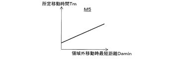
- the predetermined movement time calculation unit 51i calculates the predetermined movement time Tm based on the fifth map M5 shown in FIG.
- the fifth map M5 shows the relationship between the shortest distance Damin during movement outside the area and the predetermined movement time Tm.
- the relationship between the shortest distance Damin during movement outside the area and the predetermined movement time Tm is set so that the predetermined movement time Tm decreases as the shortest distance Damin during movement outside the area decreases.
- the detection unit shielding state detection unit 52 performs detection unit shielding state detection control (described later) for detecting whether or not the detection device 40 is in the shielding state.
- the shielding state is a state in which the detection device 40 cannot detect an obstacle because the detection unit 41 of the detection device 40 is shielded by a person or cloth that is stopped in front of the electric wheelchair 1.
- the detection unit shielding state detection unit 52 includes a predetermined detection distance calculation unit 52a, a shielding rate calculation unit 52b, a shielding rate determination value calculation unit 52c, and a first shielding state determination unit 52d (see FIG. 3).
- the predetermined detection distance calculation unit 52a calculates the predetermined detection distance Ds based on input information from the operation device 30.
- the predetermined detection distance Ds is calculated based on the sixth map M6 shown in FIG. 8 from the straight traveling speed v converted based on the input information.
- the sixth map M6 shows the relationship between the magnitude of the straight traveling speed v (absolute value
- the relationship between the magnitude of the straight traveling speed v and the predetermined detection distance Ds is set such that the smaller the magnitude of the straight traveling speed v is, the smaller the predetermined detection distance Ds is.
- the shielding rate calculation unit 52b is within the predetermined detection distance Ds from the detection unit 41 of the detection device 40 within the detection angle range Ah that is an angle range in which the detection device 40 can detect the detection object, and is detected by the detection device 40.
- the ratio of the angle occupied by the shield that is the detected object is calculated as the shielding rate Rs that is the ratio of the shield that shields the detection unit 41 of the detection device 40.
- a grid G that is within a predetermined detection distance Ds in the radial direction from the origin C0 within the detection angle range Ah is defined as a shielding rate calculation grid Gs for calculating the shielding rate Rs.
- the shielding rate Rs is calculated by the number in the circumferential direction of the shielding rate calculation grid Gs and the number in the circumferential direction of the detection object grid Gk in the shielding rate calculation grid Gs.
- the shielding rate Rs is a ratio of the number in the circumferential direction of the detection object grid Gk in the shielding rate calculation grid Gs to the number in the circumferential direction of the shielding rate calculation grid Gs.
- shielding ratio Rs (number of objects to be detected grid Gk in the circumferential direction / number of shielding ratio calculation grids Gs in the circumferential direction in the shielding ratio calculation grid Gs) ⁇ 100).
- the shielding rate determination value calculation unit 52c calculates the shielding rate determination value Ths based on input information from the operation device 30.
- the shielding rate determination value Ths is a determination value for determining whether or not the detection device 40 is in the shielding state by the first shielding state determination unit 52d.
- the shielding rate determination value Ths is calculated based on the seventh map M7 shown in FIG. 10 from the straight traveling speed v converted based on the input information.
- the seventh map M7 shows the relationship between the magnitude of the straight traveling speed v (the absolute value
- the relationship between the magnitude of the straight traveling speed v and the shielding rate determination value Ths is set so that the shielding ratio determination value Ths increases as the magnitude of the straight traveling speed v decreases.
- the first shielding state determination unit 52d determines that the detection device 40 is an obstacle. It is determined that it is a shielding state in which it cannot be detected. On the other hand, when the shielding rate Rs is smaller than the shielding rate determination value Ths, the first shielding state determination unit 52d determines that the detection device 40 is not shielded and the detection device 40 can appropriately detect an obstacle. .
- Collision risk reduction control is for the passenger to avoid obstacles by limiting the traveling speed of the electric wheelchair 1 when there is an obstacle on the predicted course Wy of the electric wheelchair 1 during the traveling control of the electric wheelchair 1. This is a control that reduces the risk of collision between the electric wheelchair 1 and the obstacle by giving a margin to the operation time.
- the control device 50 determines whether or not the position of the controller device 30 is a neutral position (step S102). When traveling control of the electric wheelchair 1 is performed, the control device 50 determines “NO” in step S102 because the operation device 30 is not in the neutral position.
- the control device 50 predicts the course of the electric wheelchair 1 based on the input information from the operation device 30 (step S104; course prediction unit 51b).
- the control device 50 generates the first region A1 and the second region A2 (step S106; first region generation unit 51c, second region generation unit 51d), and acquires detected object information from the detection device 40 (step S106). S108).
- step S110 the control device 50 determines whether or not there is an obstacle in the first area A1 or the second area A2 (step S110; obstacle presence / absence detection unit 51e).
- the control device 50 determines “NO” in step S110, and advances the program to step S112.
- step S112 the control device 50 determines whether or not the drive amount of the drive device 20 is limited.
- the control device 50 determines “NO” in step S112, and returns the program to step S102.
- steps S102 to S112 are repeatedly executed.
- step S102 to step S112 when the occupant sets the position of the operating device 30 to the neutral position in order to stop the traveling of the electric wheelchair 1, the control device 50 determines “YES” in step S102. ”And the program proceeds to step S114. At this time, since the drive amount of the drive device 20 is not restricted by the drive amount restriction unit 51f, the control device 50 determines “NO” in step S114, and returns the program to step S102. The control device 50 repeatedly executes steps S102 and S114 until the operation device 30 is operated.
- step S110 the control device 50 executes steps S102 to S108 to determine whether there is an obstacle in the first area A1 or the second area A2 (step S110; obstacle). Object presence / absence detection unit 51e).
- step S110 since there is an obstacle in the first area A1 or the second area A2, the control device 50 determines “YES” in step S110, and advances the program to step S116.
- step S116 the control device 50 determines whether the drive amount of the drive device 20 is limited.
- step S116 the control device 50 determines “NO” in step S116. And the control apparatus 50 restrict
- step S110 the first area A1 or It is determined that there is an obstacle in the second region A2 (determined as “YES” in step S110), and the program proceeds to step S116.
- the control device 50 determines “YES” in step S116, and returns the program to step S102.
- the control device 50 repeatedly executes steps S102 to S116.
- steps S102 to S116 are repeatedly executed, when the occupant sets the position of the operating device 30 to the neutral position in order to stop the traveling of the electric wheelchair 1, the control device 50 determines “YES” in step S102. And the program proceeds to step S114. At this time, since the drive amount of the drive device 20 is limited by the drive amount limiting unit 51f, the control device 50 determines “YES” in step S114. And the control apparatus 50 cancels
- the control device 50 When there is an obstacle in the first area A1, the control device 50 repeatedly executes Steps S102 to S116 as in the second case described above. And when the obstacle which exists in 1st area
- step S112 since the drive amount of the drive device 20 is limited by the drive amount limiting unit 51f, the control device 50 determines “YES” in step S112, and the obstacle is from the first region A1 to the first region. In step S124, it is determined whether or not A1 has been removed. At this time, since the control device 50 detects that the obstacle has moved out of the first region A1 by the out-of-region movement detection unit 51g, the control device 50 determines “YES” in step S124, and executes the program step. Proceed to S126.
- the control device 50 calculates a predetermined movement time Tm (step S126; predetermined movement time calculation unit 51i), and starts from a point in time when the out-of-area movement detection unit 51g detects that the obstacle has moved out of the first area A1. It is determined whether or not the movement time Tm has elapsed (step S128). When the predetermined movement time Tm has not elapsed and the traveling control is continued in a state where there is no object to be detected in each of the areas A1 and A2, the control device 50 repeatedly executes steps S128 to S138 to drive The state in which the drive amount of the device 20 is limited is maintained (drive amount limit maintaining unit 51h).
- the control device 50 determines “NO” in step S128, and in step S130, determines whether or not the position of the controller device 30 is a neutral position. Determine. When traveling control is being performed, the position of the controller device 30 is not the neutral position, and therefore the control device 50 determines “NO” in step S130. Then, the control device 50 predicts the course of the electric wheelchair 1 based on the input information (step S132; course prediction unit 51b), and generates the respective regions A1 and A2 (step S134; first region generation unit 51c, first). Two-region generation unit 51d).
- the control device 50 acquires detected object information (step S136), and determines whether or not there is an obstacle in each of the areas A1 and A2 (step S138; obstacle presence / absence detection unit 51e). If it is detected that there is no obstacle in each of the areas A1 and A2, the control device 50 determines “NO” in step S138, and returns the program to step S128.
- step S138 When the control device 50 repeatedly executes steps S128 to S138, when it is detected that the obstacle is in the first region A1 or the second region A2, the control device 50 determines “YES” in step S138. And the program is returned to step S102 in a state where the drive amount restriction of the drive device 20 by the drive amount restriction unit 51f is maintained. Further, when the control device 50 repeatedly executes steps S128 to S138, if the occupant sets the position of the operating device 30 to the neutral position in order to stop the traveling of the electric wheelchair 1, the control device 50 performs step S130. The determination is “YES” and the program proceeds to step S140. In step S140, the control device 50 releases the restriction on the drive amount of the drive device 20 by the drive amount restriction unit 51f, and returns the program to step S102.
- step S1208 determines “YES” in step S128, and advances the program to step S140.
- step S140 the control device 50 releases the restriction on the drive amount of the drive device 20 by the drive amount restriction unit 51f, and returns the program to step S102.
- step S110 the control device 50 determines “NO” in step S110, and advances the program to step S112.
- the out-of-region movement detection unit 51g does not detect that the obstacle has moved out of the first region A1.
- the control apparatus 50 determines as "YES” in step S112, and an obstruction is detected in the 1st area
- step S140 the control device 50 releases the restriction on the drive amount of the drive device 20 by the drive amount restriction unit 51f, and returns the program to step S102.
- the detection unit shielding state detection control is control for detecting whether or not the detection device 40 is in the shielding state.
- the detection unit shielding state detection control is executed while the electric wheelchair 1 is powered on.
- the control device 50 calculates the predetermined detection distance Ds based on the input information from the operation device 30 (step S202; predetermined detection distance calculation unit 52a), and calculates the shielding rate Rs (step S204; shielding rate calculation unit 52b). ). Then, the control device 50 calculates the shielding rate determination value Ths (step S206; shielding rate determination value calculation unit 52c), and the shielding rate Rs calculated by the shielding rate calculation unit 52b is calculated by the shielding rate determination value calculation unit 52c. It is determined whether or not it is equal to or greater than the calculated shielding rate determination value Ths (step S208; first shielding state determination unit 52d).
- the control device 50 determines “NO” in step S208 and returns the program to step S202. .
- the control device 50 determines “YES” in step S208.
- step S210 it is detected that the detection device 40 is in the shielding state.
- the control device 50 stops the traveling control of the electric wheelchair 1.
- the electric wheelchair 1 includes a notification device (not shown) such as a buzzer that enables notification to the occupant, the control device 50 indicates that the detection unit 41 is in a shielded state by the notification device. Inform.
- the electric wheelchair 1 is the electric wheelchair 1 that is driven by the drive device 20 that is driven in accordance with an input to the operation device 30 by the occupant, and the electric wheelchair 1 is a detection device that detects an object to be detected.
- 40 and a control device 50 that controls the driving amount of the driving device 20 to run the electric wheelchair 1 based on input information that is information input to the operating device 30.
- the control device 50 includes a first region generation unit 51c that generates a first region A1 extending along the traveling direction of the predicted course Wy of the electric wheelchair 1 predicted based on the input information, the first region A1, and the first region A1.
- an obstacle presence / absence detection unit 51e for detecting the presence / absence of an obstacle as a detected object and an obstacle presence / absence detection unit 51e A drive amount limiting unit 51f that limits the drive amount of the drive device 20 to the limit drive amount while it is detected that there is an obstacle in at least one of the inside and the second region A2.
- the possibility of a collision between the obstacle and the electric wheelchair 1 can be reduced, and the electric wheelchair 1 that can travel safely and safely can be provided. Further, when the electric wheelchair 1 passes by an obstacle, it is possible to eliminate anxiety that the occupant feels that the obstacle may collide with the obstacle.
- control device 50 detects that the electric wheelchair 1 has been moved after the detection result by the obstacle presence / absence detection unit 51e has changed from a state in which there is an obstacle in the first area A1 to a state in which there is no obstacle in the first area A1.
- a drive amount restriction maintaining unit 51h is further provided for maintaining the drive amount of the drive device 20 at the limit drive amount for the predetermined movement time Tm to move.
- the electric wheelchair 1 has the same limited driving amount as when there is an obstacle in the first region A1 for a predetermined movement time Tm from the time when the obstacle is removed from the first region A1 by the driving amount restriction maintaining unit 51h. Maintained. Therefore, for example, the electric wheelchair 1 is maintained in a state where the maximum speed of the electric wheelchair 1 is limited until an obstacle passes through the electric wheelchair 1. Therefore, the possibility of collision between the obstacle and the moving body can be reliably reduced. Further, when the electric wheelchair 1 passes by an obstacle, it is possible to eliminate anxiety that the occupant feels that the obstacle may collide with the obstacle.
- the width of the second region A2 is set to be larger than the width of the electric wheelchair 1. According to this, in the case where the obstacle and the electric wheelchair 1 approach each other, even when the obstacle once detected in the first area A1 by the detection device 40 moves out of the first area A1, This obstacle can be reliably captured in the second region A2. Thereby, the drive amount of the drive device 20 is limited by the drive amount limiting unit 51f. Therefore, the possibility of the collision between the obstacle and the electric wheelchair 1 can be further reduced. Further, when the electric wheelchair 1 passes by an obstacle, it is possible to eliminate anxiety that the occupant feels that the obstacle may collide with the obstacle.
- control device 50 is a detected object that is within a predetermined detection distance Ds from the detection unit 41 of the detection device 40 and is detected by the detection device 40 in an angular range in which the detection device 40 can detect the detection object.
- a shielding rate calculation unit 52b that calculates a rate of an angle occupied by a certain shielding object as a shielding rate Rs that is a rate at which the shielding object shields the detection unit 41 of the detection device 40, and a shielding rate calculated by the shielding rate calculation unit 52b When Rs is equal to or greater than the shielding rate determination value Ths, the first shielding state determination unit 52d that determines that the detection device 40 is in a shielding state in which an obstacle cannot be detected is further provided.
- the control device 50 can perform control, such as stopping the electric wheelchair 1, for example, warning a passenger
- the detection apparatus 40 returns to a state in which an obstacle can be detected appropriately, a state in which the possibility of a collision between the obstacle and the electric wheelchair 1 can be maintained. Further, when the electric wheelchair 1 passes by an obstacle, it is possible to eliminate anxiety that the occupant feels that the obstacle may collide with the obstacle.
- the control device 50 further includes a predetermined detection distance calculation unit 52a that calculates the predetermined detection distance Ds based on the input information. For example, when the electric wheelchair 1 is traveling at a low speed in a place where obstacles such as pedestrians are crowded, the detection unit 41 of the detection device 40 is temporarily shielded by a pedestrian or the like. The frequency with which the shielding rate Rs temporarily exceeds the shielding rate determination value Ths is high. In this case, even when a pedestrian or the like passes after approaching the electric wheelchair 1 and the detection device 40 can actually detect an obstacle located in each of the regions A1 and A2, the control device 50 There is a case where the detection device 40 is erroneously determined to be in a shielded state.
- the control device 50 calculates the shielding rate by calculating the predetermined detection distance Ds to be small by the predetermined detection distance calculation unit 52a. Rs can be made relatively low. Therefore, it is possible to suppress the shielding rate Rs from being temporarily higher than the shielding rate determination value Ths. Therefore, the control device 50 can suppress an erroneous determination that the detection device 40 is determined to be in a shielded state due to an obstacle that shields the detection device 40 temporarily. As a result, the vehicle can travel safely and safely.
- the control apparatus 50 is further provided with the shielding rate determination value calculation part 52c which calculates the shielding rate determination value Ths based on input information. For example, when the electric wheelchair 1 is traveling at a low speed in a place where obstacles such as pedestrians are crowded, the detection unit 41 of the detection device 40 is temporarily shielded by a pedestrian or the like. As described above, the control device 50 may erroneously determine that the detection device 40 is in the shielding state. On the other hand, in this embodiment, when the electric wheelchair 1 is traveling at a low speed, for example, the control device 50 greatly calculates the shielding rate determination value Ths by the shielding rate determination value calculation unit 52c. The frequency with which the shielding rate Rs temporarily exceeds the predetermined shielding rate can be suppressed. Therefore, the control device 50 can suppress an erroneous determination that the detection device 40 is determined to be in a shielded state due to an obstacle that shields the detection device 40 temporarily. As a result, the vehicle can travel safely and safely.
- the driving amount restriction maintaining unit 51h is the driving device 20 for the predetermined moving time Tm after the point in time when the out-of-region movement detecting unit 51g detects that the obstacle has moved out of the first region A1. Is maintained at the limit drive amount.
- the drive amount restriction maintaining unit 51h in the first modification is configured so that the electric wheelchair 1 is moved after the time point when the out-of-region movement detection unit 51g detects that the obstacle has moved out of the first region A1.
- the drive amount of the drive device 20 is maintained at the limited drive amount only while moving the predetermined movement distance Dm.
- the predetermined moving distance Dm is a distance that is assumed to pass through the electric wheelchair 1 from the point in time when the obstacle once detected relative to the first area A1 moves and moves outside the first area A1. is there.
- the collision risk reduction control unit 51 of the control device 50 of the first modification includes a predetermined movement distance calculation unit 151j as shown in FIG. 13 instead of the predetermined movement time calculation unit 51i of the above-described embodiment. ing.
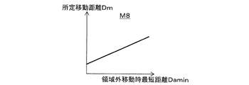
- the predetermined movement distance calculation unit 151j calculates the predetermined movement distance Dm from the shortest distance Damin during out-of-region movement based on the eighth map M8 shown in FIG.
- the eighth map M8 shows the relationship between the shortest distance Damin during movement outside the region and the predetermined movement distance Dm.
- the relationship between the shortest distance Damin during movement outside the area and the predetermined movement distance Dm is set such that the smaller the shortest distance Damin during movement outside the area, the smaller the predetermined movement distance Dm.
- the drive amount restriction maintaining unit 51h is configured to move the electric wheelchair 1 for a predetermined movement time Tm or after the time when the out-of-region movement detection unit 51g detects that the obstacle has moved out of the first region A1. While the electric wheelchair 1 moves the predetermined movement distance Dm, the drive amount of the drive device 20 is maintained at the limited drive amount.
- the detection unit shielding state detection control performed by the control device 50 in the second modification is performed by the detection unit shielding state detection unit 152 included in the control device 50 illustrated in FIG.
- the detection unit shielding state detection unit 152 includes a predetermined detection distance calculation unit 152a, a shielding rate calculation unit 152b, a shielding change rate calculation unit 152e, a predetermined shielding time calculation unit 152f, a second shielding state determination unit 152g, and a shielding change rate determination value calculation. Part 152h.
- the predetermined detection distance calculation unit 152a calculates the predetermined detection distance Ds similarly to the predetermined detection distance calculation unit 52a in the above-described embodiment.
- the shielding rate calculation unit 152b calculates the shielding rate Rs similarly to the shielding rate calculation unit 52b in the above-described embodiment.
- the shielding change rate calculation unit 152e calculates a shielding change rate Rsh that is a change rate of the shielding rate Rs.
- the shielding change rate calculation unit 152e calculates a shielding change rate Rsh, which is a change rate of the shielding rate Rs, based on the time series data of the shielding rate Rs.
- the time series data of the shielding rate Rs is data of temporal change of the shielding rate Rs calculated by the shielding rate calculation unit 152b.
- the time series data of the shielding rate Rs is formed by being stored in the storage unit 51a every first predetermined time.
- the predetermined shielding time Ts is a time calculated by the predetermined shielding time calculation unit 152f.
- the predetermined shielding time calculation unit 152f calculates the predetermined shielding time Ts based on input information from the operation device 30.
- the predetermined shielding time Ts is calculated based on the ninth map M9 shown in FIG. 16 from the straight traveling speed v converted based on the input information.
- the ninth map M9 shows the relationship between the magnitude of the straight traveling speed v (absolute value
- the relationship between the magnitude of the straight traveling speed v and the predetermined shielding time Ts is set so that the predetermined shielding time Ts increases as the magnitude of the straight traveling speed v decreases.
- the second shielding state determination unit 152g determines that the detection device 40 is in a shielding state in which an obstacle cannot be detected when the shielding change rate Rsh calculated by the shielding change rate calculation unit 152e is equal to or less than the shielding change rate determination value Thsh. To do.
- the shielding change rate determination value Thsh is calculated by the shielding change rate determination value calculation unit 152h.
- the shielding change rate determination value calculation unit 152h calculates the shielding change rate determination value Thsh based on input information from the operating device 30.
- the shielding change rate determination value calculation unit 152h is calculated based on the tenth map M10 shown in FIG.
- the tenth map M10 shows the relationship between the magnitude of the straight traveling speed v (absolute value
- the relationship between the magnitude of the straight traveling speed v and the shielding change rate determination value Thsh is set so that the shielding change rate determination value Thsh increases as the magnitude of the straight traveling speed v decreases.
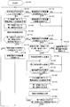
- the detection part shielding state detection control which the control apparatus 50 of this 2nd modification performs is demonstrated along the flowchart shown in FIG.
- the control device 50 calculates the predetermined detection distance Ds based on the input information from the operation device 30 (step S302; predetermined detection distance calculation unit 152a), and calculates the shielding rate Rs (step S304; shielding rate calculation unit 152b). ). And the control apparatus 50 memorize
- step S308 the control device 50 determines whether or not the calculated shielding rate Rs is zero.
- the control device 50 determines “YES” in step S308, and returns the program to step S302.
- the control device 50 determines “NO” in step S308, and the program is executed in step S310. Proceed to
- the control device 50 calculates a predetermined shielding time Ts (step S310; predetermined shielding time calculation unit 152f).
- step S312 the control device 50 extracts the current shielding rate Rsn and the previous shielding rate Rsb from the time series data.
- the control device 50 sets the front shielding rate Rsb to zero.
- step S314 control device 50 determines whether or not front shielding rate Rsb is zero.
- the control device 50 determines “YES” in step S314.
- the program is then returned to step S302.
- the control device 50 determines “NO” in step S314, and advances the program to step S316.
- the control device 50 calculates a shielding change rate Rsh (step S316; shielding change rate calculation unit 152e), and calculates a shielding change rate determination value Thsh based on the input information from the operation device 30 (step S318; shielding change rate). Determination value calculation unit 152h). Then, the control device 50 determines whether or not the shielding change rate Rsh is equal to or less than the shielding change rate determination value Thsh (Step S320; second shielding state determination unit 152g). When the detection unit 41 of the detection device 40 continues to be shielded by a shield such as cloth, the shielding change rate Rsh is relatively small, and therefore the shielding change rate Rsh is equal to or less than the shielding change rate determination value Thsh.
- control device 50 determines “YES” in step S320, and detects the shielding state of the detection device 40 in step S322.
- the shielding change rate Rsh is relatively large, so the shielding change rate Rsh is shielded. It becomes larger than the change rate determination value Thsh.
- control device 50 determines “NO” in step S320, and returns the program to step S302.
- the control device 50 is within the predetermined detection distance Ds from the detection unit 41 of the detection device 40 within the angular range in which the detection device 40 can detect the detected object.
- a shielding rate calculation unit 152b that calculates a ratio of an angle occupied by a shield that is a detected object as a shielding rate Rs that is a rate at which the shielding object shields the detection unit 41 of the detection device 40;
- the shielding change rate calculation unit 152e that calculates the shielding change rate Rsh, which is the rate of change, and the shielding change rate Rsh calculated by the shielding change rate calculation unit 152e is equal to or less than the shielding change rate determination value Thsh
- the detection device 40 A second shielding state determination unit 152g that determines that the object is in a shielding state in which an object cannot be detected.
- the control device 50 may erroneously determine that the detection device 40 is in the shielding state.
- the control device 50 in the second modified example determines whether or not the detection device 40 is in the shielding state in consideration of the shielding change rate Rsh calculated by the shielding change rate calculation unit 152e. Therefore, it is possible to suppress an erroneous determination that the detection device 40 is determined to be in a shielding state due to an obstacle that temporarily blocks the detection unit 41 of the detection device 40.
- the moving body is the electric wheelchair 1, but instead of this, a boarding type moving body such as a small vehicle or a mobile robot may be used.
- the operation device 30 is a joystick. Instead, the operation device 30 is configured by an accelerator that indicates the straight traveling speed of the electric wheelchair 1 and a handle that indicates the turning direction of the electric wheelchair 1. You may make it do.
- the detection device 40 is a three-dimensional range sensor that detects the three-dimensional position information of the detection object. Instead, the detection device 40 detects the two-dimensional position information of the detection object.
- a dimensional range sensor may be used.
- the electric wheelchair 1 is provided with one detection apparatus 40, it may replace with this and may be provided with multiple detection apparatuses 40. According to this, compared with the case where the number of the detection devices 40 is one, the detection angle range Ah in which the detection object of the detection device 40 can be detected can be expanded.
- the first region A1 and the second region A2 are generated in a planar shape on the polar coordinates C. Instead, the first region A1 and the second region A2 are generated three-dimensionally. You may make it do.
- the first area A1 and the second area A2 may be generated on the spherical coordinates centered on the electric wheelchair 1. Accordingly, the height of the first area A1 and the height of the second area A2 can be set differently within a range in which the detection device 40 can detect the detection object.
- the origin C0 of the polar coordinate C is the position of the detection unit 41 of the detection device 40.
- the origin C0 of the polar coordinate C may be the center of gravity of the electric wheelchair 1, for example. In this case, the coordinate data which is the detected object information from the detection device 40 is corrected, and projection onto the polar coordinates C is performed.
- region A2 is produced
- the control device 50 generates the second region A2 by the second region generation unit 51d, but instead of this, the second region A2 may not be generated.
- the maximum speed of the straight traveling speed v limited by the drive amount limiting unit 51f changes according to the shortest distance Dmin.
- the electric wheelchair 1 may change according to the relative speed of the obstacle and the density of the obstacle in the grid G (density of the point group PG).
- the drive amount limiting unit 51f may limit the maximum speed of the straight traveling speed v to a constant speed regardless of the shortest distance Dmin.
- the maximum amount of the straight traveling speed v is limited by setting the driving amount of the driving device 20 to the limiting driving amount by the driving amount limiting unit 51f, but instead, the straight traveling speed is limited. You may make it reduce v uniformly by a predetermined ratio. Further, the time change rate (acceleration) of the straight traveling speed v may be limited.
- the maximum speed of the straight traveling speed v limited by the drive amount limiting unit 51f is set to a constant speed.
- the distance may change according to the shortest distance Dmin, the relative speed between the electric wheelchair 1 and the obstacle, and the density of the obstacle in the grid G (density of the point group PG).
- the predetermined movement time calculation unit 51i calculates the predetermined movement time Tm from the shortest distance Damin during out-of-region movement. Instead, the relative speed between the electric wheelchair 1 and the obstacle is calculated. Alternatively, the predetermined movement time Tm may be calculated from the density of obstacles in the grid G (the density of the point group PG). In the above-described embodiment, the predetermined movement time Tm is calculated by the predetermined movement time calculation unit 51i, but instead of this, the predetermined movement time Tm may be set to a certain time in advance. In this case, it is assumed that the predetermined movement time Tm passes through the electric wheelchair 1 from the time when the obstacle once detected relative to the first area A1 moves relatively outside the first area A1. The preset time is set in advance (for example, 10 seconds).
- the predetermined movement distance Dm is calculated by the predetermined movement distance calculation unit 151j, but instead of this, the predetermined movement distance Dm may be set to a fixed distance in advance. In this case, it is assumed that the predetermined moving distance Dm passes through the electric wheelchair 1 from the time when the obstacle once detected relative to the first area A1 moves relative to the outside and moves out of the first area A1. Distance (for example, 5 m).
- the shielding rate calculation unit 52b calculates the shielding rate Rs using the grid G.
- the shielding rate Rs is directly calculated from the detected object information (the coordinate data of the point group PG). It may be calculated. Specifically, a circumferential angle range in which an obstacle exists within a predetermined detection distance Ds is calculated from the coordinate data of the point group PG.
- the shielding rate Rs is calculated as a ratio with respect to the detection angle range Ah of the detection device 40 in this angle range.
- the predetermined shielding time Ts is calculated by the predetermined shielding time calculation unit 152f. Instead, the predetermined shielding time Ts is set to a predetermined time (for example, 5 seconds) in advance. You may make it set.
- the shielding change rate determination value Thsh is calculated by the shielding change rate determination value calculation unit 152h. Instead, the shielding change rate determination value Thsh is set to a constant value ( For example, it may be set in advance to 10%.
- the second area A2 is generated with a predetermined size along the traveling direction of the predicted course Wy by the second area generating unit 51d.
- the wheelchair 1) may be configured to be fixed in advance in a predetermined direction (for example, in front of the electric wheelchair 1).
- the mobile body (electric wheelchair 1) includes a plurality of detection devices 40
- the first region A1 and the second region A2 may be set based on different detection devices 40, respectively.
- the drive amount limiting unit 51f calculates the second maximum straight traveling speed vx2 based on the fourth map M4.
- the second maximum straight traveling speed vx2 may be a predetermined fixed value set in advance.
- the drive amount limiting unit 51f is detected by the obstacle presence / absence detection unit 51e that there is an obstacle in at least one of the first region A1 and the second region A2.
- the drive amount of the drive device 20 is limited to the limit drive amount, if the desired straight travel speed xjs input to the operation device 30 is smaller than the first maximum straight travel speed vx1 and the second maximum straight travel speed vx2, the drive amount The restriction may be released.
- the predetermined time Tm during which the electric wheelchair 1 moves or the electric wheelchair 1 The drive amount of the drive device 20 is maintained at the limited drive amount while the vehicle travels the predetermined movement distance Dm.
- this drive limit method is a limited drive amount gradually or gradually from the time when the state changes to the state of no obstacle. May be changed.
- the out-of-region movement detection unit 51g is configured to detect the relative obstacle detected as being in the first region A1 based on the detection result of the obstacle detected by the obstacle presence / absence detection unit 51e. It is detected that it has moved out of the first area A1. Instead, the out-of-area movement detection unit 51g relatively moves the obstacle detected as being in the second area A2 based on the detection result of the obstacle detected by the obstacle presence / absence detection unit 51e. Then, it may be detected that the second area A2 is out of the second area A2.
- the predetermined amount of time Tm during which the electric wheelchair 1 moves after the time when the out-of-region movement detection unit 51g detects that the obstacle has moved out of the second region A2 is detected by the driving amount restriction maintaining unit 51h.
- the drive amount of the drive device 20 may be maintained at the limited drive amount while the electric wheelchair 1 moves the predetermined movement distance Dm. That is, the drive amount restriction maintaining unit 51h is electrically operated after the detection result by the obstacle presence / absence detection unit 51e changes from a state in which there is an obstacle in the second region A2 to a state in which there is no obstacle in the second region A2.
- the control device 50 determines whether the electric wheelchair 1 moves for a predetermined movement time Tm or the electric wheelchair 1 after the detection result by the obstacle presence / absence detection unit 51e changes from the obstacle presence state to the obstacle absence state. Is further provided with a drive amount restriction maintaining unit 51h that maintains the drive amount of the drive device 20 at the limit drive amount while moving the predetermined movement distance Dm.
- a moving body that is driven by a driving device that is driven in accordance with an input to the operating device by an occupant, wherein the moving body includes a detection device that detects an object to be detected, and input information that is information input to the operating device.
- a control unit that controls the driving amount of the drive unit to cause the mobile unit to travel, and the control unit predicts a path of the mobile unit based on the input information;
- a first region generating unit that generates a first region extending along a traveling direction of a predicted route that is a route of the moving body predicted by the route predicting unit; and the first region generating unit that is generated by the first region generating unit.
- Presence / absence of an obstacle that is the detected object that is further than the predetermined detection distance from the detection unit of the detection device based on the detected object information that is detected by the detection device within one area Drive that limits the drive amount of the drive device to a limited drive amount while the obstacle presence / absence detection unit to be detected and the obstacle presence / absence detection unit detect that the obstacle exists in the first region Based on the information on the obstacle detected by the amount limiting unit and the obstacle presence / absence detecting unit, the obstacle detected as being within the first region moves relatively outside the first region. After the point in time when the out-of-region movement detection unit that detects that the obstacle has moved out of the first region is detected by the out-of-region movement detection unit, And a drive amount restriction maintaining unit that maintains the limit drive amount.
- Appendix 2 A moving body that is driven by a driving device that is driven in accordance with an input to the operating device by an occupant, wherein the moving body includes a detection device that detects an object to be detected, and input information that is information input to the operating device. And a control device configured to control the driving amount of the driving device to cause the moving body to travel, the control device in a traveling direction of the predicted course of the moving body predicted based on the input information.
- a region generation unit that generates at least one of the first region extending along the second region as a peripheral region within a predetermined distance from the moving body (the first region generation unit 51c and the first region generation unit 51c in the embodiment described above)
- Two-region generating unit 51d) and an obstacle presence / absence determining unit that determines whether or not there is an obstacle in the region generated by the region generating unit based on the detection result of the detection device (upper) Drive corresponding to the obstacle detection unit 51e) and the obstacle presence / absence determination unit while the obstacle is determined to be present, while the drive amount of the drive device is limited to a limited drive amount.
- a predetermined amount of time during which the moving body moves after the determination result of the obstacle presence / absence determination unit changes from a state with an obstacle to a state without an obstacle.
- the moving body that maintains the driving amount of the driving device at the limit driving amount while the moving body moves a predetermined moving distance is a predetermined moving distance.
- SYMBOLS 1 Electric wheelchair, 10 ... Wheelchair main body, 20 ... Drive apparatus, 30 ... Operation apparatus, 40 ... Detection apparatus, 41 ... Detection part, 50 ... Control apparatus, 51 ... Collision risk reduction control part, 51b ... Course prediction part, 51c ... 1st area
- first shielding state determination unit, 152e ... shielding change rate calculation unit, 152g ... second shielding state determination unit, A1 ... first region, A2 ... second region, Ah: Detection angle range, C: Polar coordinates, Dm: Predetermined movement distance, Ds: Predetermined detection distance, Rs: Shielding rate, Rsh: Shielding change rate, Ths: Shielding rate determination value, Thsh: Shielding change rate determination value, Tm ... Predetermined travel time, Wy ... predicted progress .
Landscapes
- Engineering & Computer Science (AREA)
- Physics & Mathematics (AREA)
- Electromagnetism (AREA)
- Computer Networks & Wireless Communication (AREA)
- General Physics & Mathematics (AREA)
- Radar, Positioning & Navigation (AREA)
- Remote Sensing (AREA)
- Mechanical Engineering (AREA)
- Transportation (AREA)
- Life Sciences & Earth Sciences (AREA)
- Power Engineering (AREA)
- General Health & Medical Sciences (AREA)
- Health & Medical Sciences (AREA)
- Animal Behavior & Ethology (AREA)
- Automation & Control Theory (AREA)
- Public Health (AREA)
- Veterinary Medicine (AREA)
- Sustainable Development (AREA)
- Sustainable Energy (AREA)
- Electric Propulsion And Braking For Vehicles (AREA)
- Control Of Position, Course, Altitude, Or Attitude Of Moving Bodies (AREA)
Abstract
障害物を検知する検知装置を備えた移動体において、検知装置によって検知される領域にあることにより検知された障害物が相対的に移動して、その領域から外れて移動体に近づくような場合においても、安全かつ安心して走行できる移動体を提供する。移動体である電動車椅子の制御装置は、操作装置からの入力情報に基づいて予測される電動車椅子の予測進路の進行方向に沿って延びる第一領域内、および電動車椅子から所定距離以内の周辺領域としての第二領域内において、障害物の有無を検出する障害物有無検出部と、障害物有無検出部によって、第一領域内および第二領域内の少なくともいずれか一方に障害物が有ると検出されている間、駆動装置の駆動量を制限駆動量に制限する駆動量制限部と、を備えている。
Description
本発明は、移動体、特に、乗員の操作によって走行する移動体に関する。
操作されることにより移動する移動体の一形式として、特許文献1に示されているものが知られている。特許文献1の図1および図2に示すように、移動体は、例えば電動車いすであり、電動車いすは、検知エリア内の物体を検知する物体検知センサ19、車輪を駆動するモータ5、モータ5の駆動量を制御して電動車いすの走行制御を行う制御回路25を備えている。制御回路25は、物体検知センサ19からの検知信号が入力された場合、電動車いすの最大速度を制限する駆動制御手段を備えている。これにより、電動車いすと歩行者等の障害物との衝突の可能性を低減することができる。
しかしながら、障害物が歩行者等の移動するものである場合、障害物が物体検知センサ19によって検知された後、障害物が検知エリア外へ移動する場合がある。さらに、障害物が移動して、検知エリアの死角から電動車いすに近づくような場合には、障害物が検知エリアから外れていることにより、電動車いすの最大速度の制限が解除されているため、電動車いすと障害物との衝突の可能性を低減することができない。
そこで、本発明は、上述した課題を解消するためになされたもので、障害物を検知する検知装置を備えた移動体において、検知装置によって検知される領域にあることにより検知された障害物が相対的に移動して、その領域から外れて移動体に近づくような場合においても、安全かつ安心して走行することができる移動体を提供することを目的とする。
上記の課題を解決するため、請求項1に係る移動体は、乗員による操作装置への入力に従って駆動される駆動装置によって走行する移動体であって、移動体は、被検知物を検知する検知装置と、操作装置に入力された情報である入力情報に基づいて、駆動装置の駆動量を制御して移動体を走行させる制御装置と、を備え、制御装置は、入力情報に基づいて予測される移動体の予測進路の進行方向に沿って延びる第一領域を生成する第一領域生成部と、第一領域内、および移動体から所定距離以内の周辺領域としての第二領域内において、被検知物である障害物の有無を検出する障害物有無検出部と、障害物有無検出部によって、第一領域内および第二領域内の少なくともいずれか一方に障害物が有ると検出されている間、駆動装置の駆動量を制限駆動量に制限する駆動量制限部と、を備えている。
これによれば、障害物と移動体とが接近するような場合において、検知装置によって第一領域内で一旦検知された障害物が第一領域外へ外れたときにおいても、この障害物を移動体の周辺領域である第二領域により捕捉することができる。したがって、障害物と移動体との衝突の可能性を低減することができるとともに、安全かつ安心して走行することができる移動体を提供することができる。
以下、本発明による移動体の一実施形態について図面を参照して説明する。本実施形態における移動体として、図1に示す電動車椅子1を例に挙げて説明する。なお、本明細書においては説明の便宜上、図1における上側および下側をそれぞれ電動車椅子1の上方および下方とし、同じく左下側および右上側をそれぞれ電動車椅子1の前方および後方とし、同じく左上側および右下側を、それぞれ電動車椅子1の右方および左方として説明する。また、図1には、各方向を示す矢印を示している。
電動車椅子1は、車椅子本体10、駆動装置20、操作装置30、検知装置40および制御装置50を備えている。電動車椅子1は、乗員による操作装置30への入力に従って駆動される駆動装置20によって走行する移動体である。駆動装置20、操作装置30、検知装置40および制御装置50は、車椅子本体10に取り付けられている。
車椅子本体10は、フレーム11、乗員が着座する座席12および車輪13を備えている。座席12および車輪13は、フレーム11に取り付けられている。車輪13は、回転軸回りに回転可能に構成されている。車輪13は、車椅子本体10の左右両側に配設され、駆動装置20によって駆動される左駆動輪13aおよび右駆動輪13b、並びに、電動車椅子1の走行を補助する左補助輪13cおよび右補助輪13dを備えている。
駆動装置20は、各駆動輪13a,13bをそれぞれ回転駆動させて、電動車椅子1を走行させるものである。駆動装置20は、例えば、電動モータ(図示なし)と減速機(図示なし)とを組み合わせることにより構成されている。駆動装置20は、各駆動輪13a,13bにそれぞれ1つずつ(合計2つ)設けられている。
操作装置30は、電動車椅子1の直進速度vおよび旋回速度wを指示するために乗員によって操作されるものである。直進速度vは、電動車椅子1の前方向(正面方向)における電動車椅子1の速度である。旋回速度wは、電動車椅子1の位置する場所において、電動車椅子1が電動車椅子1の重心を中心に旋回する角速度である。本実施形態において、操作装置30は、ジョイスティックである。操作装置30は、操作されていない位置(以下、ニュートラル位置とする)において、鉛直方向に起立した状態で位置決めされている。操作装置30は、ニュートラル位置から乗員に傾けられることにより操作される。操作装置30が操作された状態は、図2に示すように、操作装置30を水平面と平行なXY平面に投影したときにおける操作装置30の先端の座標によって表すことができる。X軸は、電動車椅子1の前後方向と同じであり、X軸の正の方向は、電動車椅子1の前方向と同じ方向である。Y軸は、電動車椅子1の左右方向と同じであり、Y軸の正の方向は、電動車椅子1の右方向と同じ方向である。X座標の値は、乗員が所望する電動車椅子1の直進速度である所望直進速度xjsである。Y座標の値は、乗員が所望する電動車椅子1の旋回速度である所望旋回速度yjsである。所望直進速度xjsおよび所望旋回速度yjsは、操作装置30に入力された情報である入力情報として、制御装置50に第一所定時間毎に出力される。第一所定時間は、例えば、1/25秒である。
検知装置40は、被検知物を検知するものである。被検知物には、障害物と遮蔽物とがある。障害物は、検知装置40の検知部41から所定検知距離Dsより離れた被検知物である。遮蔽物は、検知装置40の検知部41から所定検知距離Ds内にある被検知物である。所定検知距離Dsは、比較的短い距離(例えば、10cm)である。所定検知距離Dsは、操作装置30からの入力情報に基づいて算出される(後述する)。なお、上記において、障害物を検知する場合と遮蔽物を検知する場合のそれぞれの所定検知距離Dsは等しく設定されているが、所定検知距離Dsは、それぞれの場合に応じて異なる検知距離を設定しても良い。
検知装置40は、3次元測域センサ(レーザーレンジスキャナー(3Dスキャナー))である。検知装置40は、検知部41からレーザーを水平方向および上下方向に(三次元的に)発射して、被検知物からの反射波を検知部41にて受信することにより、被検知物の有無および検知部41から被検知物までの距離を被検知物情報として取得する。検知装置40は、レーザーを電動車椅子1の前方に放射状に発射する。レーザーの発射可能な角度範囲は、検知装置40が被検知物を検知可能な角度範囲に相当する。検知装置40は、例えば、第一所定時間毎に被検知物情報を取得する。検知装置40が取得した被検知物情報は、制御装置50に出力される。
制御装置50は、入力情報に基づいて、駆動装置20の駆動量を制御して電動車椅子1を走行させるものである。制御装置50は、図3に示すように、駆動装置20、操作装置30および検知装置40が接続されている。制御装置50が電動車椅子1を走行させる走行制御について説明する。操作装置30が操作され、操作装置30からの入力情報を制御装置50が取得した時点から、制御装置50は、走行制御を開始する。制御装置50は、操作装置30からの入力情報(所望直進速度xjsおよび所望旋回速度yjs)を、直進速度vおよび旋回速度wに変換する。制御装置50は、取得した所望直進速度xjsから、図4Aに示す第一マップM1に基づいて、直進速度vを算出する。第一マップM1は、所望直進速度xjsと直進速度vとの関係を示したものである。また、制御装置50は、取得した所望旋回速度yjsから、図4Bに示す第二マップM2に基づいて、旋回速度wを算出する。第二マップM2は、所望旋回速度yjsと旋回速度wとの関係を示したものである。
第一マップM1は、図4Aに示すように、所望直進速度xjsと直進速度vとが、比例する比例部mv1と、所望直進速度xjsの大きさにかかわらず直進速度vが一定の値である不感部mv2備えている。直進速度vが正である場合、電動車椅子1が前進する。一方、直進速度vが負である場合、電動車椅子1が後退する。また、第二マップM2は、図4Bに示すように、所望旋回速度yjsと旋回速度wとが比例する比例部mw1と、所望旋回速度yjsの大きさにかかわらず旋回速度wが一定の値である不感部mw2を備えている。旋回速度wが正である場合、電動車椅子1が右旋回する。一方、旋回速度wが負である場合、電動車椅子1が左旋回する。
制御装置50は、変換された直進速度vおよび旋回速度wに基づいて、駆動装置20の駆動量(回転数)を制御する。具体的には、変換された直進速度vおよび旋回速度wが、左駆動輪13aの回転速度および右駆動輪13bの回転速度にさらに変換される。直進速度vの大きさは、各駆動輪13a,13bの回転速度の大きさに比例する。また、旋回速度wの大きさは、左駆動輪13aと右駆動輪13bとの回転速度の差の大きさに比例する。直進速度vおよび旋回速度wと各駆動輪13a,13bの回転速度との関係は、予め実験等により実測されて導出されている。なお、駆動装置20がPWM制御されているため、駆動装置20の制御指令値は、デューティ比にて算出される。
制御装置50が走行制御を行っている際に、乗員が操作装置30の位置をニュートラル位置にした場合、直進速度vおよび旋回速度wがゼロとなることで、電動車椅子1が停止する。この場合、制御装置50の走行制御が終了する。
また、制御装置50は、図3に示すように、衝突リスク低減制御部51および検知部遮蔽状態検出部52を備えている。衝突リスク低減制御部51は、電動車椅子1と障害物との衝突するリスクを低減する衝突リスク低減制御(後述する)を行うものである。衝突リスク低減制御部51は、記憶部51a、進路予測部51b、第一領域生成部51c、第二領域生成部51d、障害物有無検出部51e、駆動量制限部51f、領域外移動検出部51g、駆動量制限維持部51hおよび所定移動時間算出部51iを備えている。
記憶部51aは、制御プログラムを実行する際に用いられる各マップM1,M2および極座標C(後述する)等のデータ等を記憶するものである。
記憶部51aは、制御プログラムを実行する際に用いられる各マップM1,M2および極座標C(後述する)等のデータ等を記憶するものである。
進路予測部51bは、入力情報に基づいて、電動車椅子1の進路を予測するものである。進路予測部51bは、図5に示すように、極座標C上にて、電動車椅子1の進路を予測する。極座標Cは、水平面と平行に配設され、検知装置40の検知部41の位置を原点C0とするとともに、図5の上側を電動車椅子1の前方とした極座標である。極座標Cは、径方向および周方向に所定間隔(例えば、径方向に50cm間隔および径方向に5°間隔)に区画された複数のグリッドGを有している。進路予測部51bが予測する電動車椅子1の進路である予測進路Wyは、具体的には、制御装置50が入力情報を取得した時点から第二所定時間(例えば5秒)経過した時点までの検知部41が通過すると予測される線状の移動軌跡にて示される。予測進路Wyは、直進速度vおよび旋回速度wから、予め実験等により実測されて導出された所定の関数に基づいて生成される。予測進路Wyは、制御装置50が操作装置30からの入力情報を取得する第一所定時間毎に生成(更新)される。
第一領域生成部51cは、進路予測部51bによって予測された電動車椅子1の進路である予測進路Wyの進行方向に沿って延びる第一領域A1を生成するものである。第一領域A1は、極座標C上において、予測進路Wyが位置するグリッドGを含むように生成される。本実施形態においては、第一領域A1は、例えば、予測進路Wyが位置するグリッドGと、そのグリッドGの周方向に隣り合う複数(例えば、両側2個づつ)のグリッドGとから、予測進路Wyの進行方向に沿って延びる略扇形に生成されている。第一領域A1の形状は、入力情報の変化による予測進路Wyの変化に応じて変化する。
第二領域生成部51dは、所定の大きさの第二領域A2を予測進路Wyの進行方向に沿って生成するものである。第二領域A2は、他人に近付かれると不快に感じる空間であるパーソナルエリアの大きさを考慮された領域である。具体的には、第二領域A2は、電動車椅子1(電動車椅子1の重心)から所定距離以内の周辺領域である。所定距離は、比較的短い距離(例えば、2m)である。第二領域A2は、極座標C上において、所定の大きさに予め設定された原点C0を中心とする扇形に生成される。第二領域A2は、本実施形態において、第一領域A1の大きさと比べて、周方向の角度範囲が大きくなるように、かつ、第二領域A2の幅(左右方向長さの最大長さ)が、電動車椅子1の幅(左右方向長さの最大長さ)より大きくなるように設定されている。具体的には、第二領域A2の径方向長さは、原点C0から5つのグリッドG分の長さに設定されている。第二領域A2の周方向の角度範囲は、検知装置40が被検知物を検知可能な極座標C上の周方向の角度範囲である検知角度範囲Ahと同じ角度範囲に設定されている。
障害物有無検出部51eは、第一領域生成部51cによって生成された第一領域A1内および第二領域生成部51dによって生成された第二領域A2内において、検知装置40によって検知された被検知物の情報である被検知物情報に基づいて、障害物の有無を検出するものである。障害物有無検出部51eが行う障害物の有無を検出する障害物有無検出制御について説明する。はじめに、検知装置40からの被検知物情報が、極座標Cに投影される。被検知物情報は、被検知物の三次元位置情報を表す複数の点Pから構成された点群PGの座標データである。極座標Cに投影された点群PGを構成する点Pの個数が所定個数以上であるグリッドGが、被検知物が存在するグリッドGである被検知物グリッドGkとされる。所定個数は、例えば5個である。被検知物グリッドGkが第一領域A1内にある場合、障害物有無検出部51eは、第一領域A1内に障害物有りと検出する。また、被検知物グリッドGkが第二領域A2内にある場合、障害物有無検出部51eは、第二領域A2内に障害物有りと検出する。一方、被検知物グリッドGkが第一領域A1内に無い場合、障害物有無検出部51eは、第一領域A1内に障害物無しと検出する。また、被検知物グリッドGkが第二領域A2内に無い場合、障害物有無検出部51eは、第二領域A2内に障害物無しと検出する。被検知物情報が第一所定時間毎に取得されるため、障害物有無検出部51eが行う障害物有無検出制御は、第一所定時間毎に実行される。すなわち、第一領域A1内および第二領域A2内に障害物の有無の検出結果は、第一所定時間毎に更新される。なお、図5には、第一領域A1内に障害物が有り、第二領域A2内に障害物が無い状態が示されている。
駆動量制限部51fは、障害物有無検出部51eによって第一領域A1内および第二領域A2内の少なくともいずれか一方に障害物が有ると検出されている間、駆動装置20の駆動量を制限駆動量に制限するものである。本実施形態においては、制限駆動量は、駆動装置20の駆動量の最大駆動量を制限する駆動量である。すなわち、駆動装置20の最大駆動量が制限駆動量に制限されることにより、直進速度vの最高速度が制限される。具体的には、第一領域A1内に障害物が有ると検出されている間、駆動量制限部51fは、直進速度vの最高速度を第一最高直進速度vx1に制限する。第一最高直進速度vx1は、電動車椅子1(検知装置40の検知部41(原点C0))から障害物までの最短距離Dmin(図5参照)から、図6Aに示す第三マップM3に基づいて算出される。最短距離Dminは、被検知物情報から算出することができる。最短距離Dminは、障害物有無検出部51eにより障害物が有ると検出されている間、駆動量制限部51fによって算出される。第三マップM3は、最短距離Dminと第一最高直進速度vx1との関係を示したものである。最短距離Dminと第一最高直進速度vx1との関係は、最短距離Dminが小さい程、第一最高直進速度vx1が小さくなるように設定されている。
また、第二領域A2内に障害物が有ると検出されている場合、駆動量制限部51fは、直進速度vの最高速度を第二最高直進速度vx2に制限する。第二最高直進速度vx2は、最短距離Dminから、図6Bに示す第四マップM4に基づいて算出される。第四マップM4は、最短距離Dminと第二最高直進速度vx2との関係を示したものである。第二最高直進速度vx2は、最短距離Dminの大きさにかかわらず、一定の速度となるように設定されている。なお、第一領域A1と第二領域A2との重複領域A3(図5参照)に障害物が有ると検出された場合、直進速度vの最高速度は、第一最高直進速度vx1と第二最高直進速度vx2とを比較して小さい方の速度に制限される。
領域外移動検出部51gは、障害物有無検出部51eによって検出された障害物の検出結果に基づいて、第一領域A1内に有ると検出された障害物が相対的に移動して、第一領域A1外へ外れたことを検出するものである。領域外移動検出部51gは、障害物有無検出部51eによって検出された障害物の検出結果が入力される。この障害物の検出結果は、第一領域A1内の障害物の有無である。例えば、障害物が、第一領域A1内にて移動している場合、「第一領域A1内に障害物有り」の検出結果が領域外移動検出部51gに入力される。その後、その障害物が、第一領域A1外へ外れた場合、「第一領域A1内に障害物無し」旨の検出結果が領域外移動検出部51gに入力される。これにより、領域外移動検出部51gは、障害物有無検出部51eからの検出情報が、「第一領域A1内に障害物有り」から「第一領域A1内に障害物無し」に変化した時点に、障害物が相対的に移動して、第一領域A1内から第一領域A1外へ外れたことを検出する。
駆動量制限維持部51hは、領域外移動検出部51gによって、障害物が第一領域A1外へ外れたことを検出された時点以降、所定移動時間Tmだけ、駆動装置20の駆動量を制限駆動量に維持するものである。すなわち、駆動量制限維持部51hは、第一領域A1内に有ると一旦検出された障害物が第一領域A1外へ外れた時点以降、所定移動時間Tmだけ、駆動量制限維持部51hによって、第一領域A1内に障害物があるときと同じ制限駆動量を維持される。所定移動時間Tmは、第一領域A1内に有ると一旦検出された障害物が相対的に移動して、第一領域A1外へ外れた時点から、電動車椅子1を通り過ぎると想定される時間である。所定移動時間Tmは、所定移動時間算出部51iによって算出される。
所定移動時間算出部51iは、電動車椅子1と障害物との最短距離Dminから、所定移動時間Tmを算出するものである。所定移動時間Tmが算出されるときの最短距離Dminは、第一領域A1内に有ると一旦検出された障害物が相対的に移動して、第一領域A1外へ外れた時点の最短距離Dminである領域外移動時最短距離Daminである。所定移動時間算出部51iは、領域外移動時最短距離Daminから図7に示す第五マップM5に基づいて、所定移動時間Tmを算出する。第五マップM5は、領域外移動時最短距離Daminと所定移動時間Tmとの関係を示すものである。領域外移動時最短距離Daminと所定移動時間Tmとの関係は、領域外移動時最短距離Daminが小さい程、所定移動時間Tmが小さくなるように設定されている。
検知部遮蔽状態検出部52は、検知装置40が遮蔽状態であるか否かを検出する検知部遮蔽状態検出制御(後述する)を行うものである。遮蔽状態は、検知装置40の検知部41が、電動車椅子1の前方に立ち止っている人や布等によって遮蔽されていることにより、検知装置40が障害物を検知できない状態である。検知部遮蔽状態検出部52は、所定検知距離算出部52a、遮蔽率算出部52b、遮蔽率判定値算出部52c、および第一遮蔽状態判定部52dを備えている(図3参照)。
所定検知距離算出部52aは、操作装置30からの入力情報に基づいて、所定検知距離Dsを算出するものである。所定検知距離Dsは、入力情報に基づいて変換された直進速度vから、図8に示す第六マップM6に基づいて算出される。第六マップM6は、直進速度vの大きさ(直進速度vの絶対値|v|)と所定検知距離Dsとの関係を示すものである。直進速度vの大きさと所定検知距離Dsとの関係は、直進速度vの大きさが小さい程、所定検知距離Dsが小さくなるように設定されている。
遮蔽率算出部52bは、検知装置40が被検知物を検知可能な角度範囲である検知角度範囲Ahのうち、検知装置40の検知部41から所定検知距離Ds内にあって検知装置40によって検知された被検知物である遮蔽物が占める角度の割合を、遮蔽物が検知装置40の検知部41を遮蔽する割合である遮蔽率Rsとして算出するものである。具体的には、図9に示す極座標Cにおいて、検知角度範囲Ah内における原点C0から径方向に所定検知距離Ds内にあるグリッドGを、遮蔽率Rsを算出するための遮蔽率算出グリッドGsとする。そして、遮蔽率Rsは、遮蔽率算出グリッドGsの周方向の個数と、遮蔽率算出グリッドGs内にある被検知物グリッドGkの周方向の個数とによって算出される。具体的には、遮蔽率Rsは、遮蔽率算出グリッドGsの周方向の個数に対する遮蔽率算出グリッドGs内にある被検知物グリッドGkの周方向の個数の割合である。(遮蔽率Rs=(被検知物グリッドGkの周方向の個数/遮蔽率算出グリッドGs内にある遮蔽率算出グリッドGsの周方向の個数)×100)。なお、図9において、遮蔽率算出グリッドGsの周方向の個数が28個であり、遮蔽率算出グリッドGs内にある被検知物グリッドGkの周方向の個数が17個であるため、遮蔽率Rsは、およそ61(=(17/28)×100)%である。
遮蔽率判定値算出部52cは、操作装置30からの入力情報に基づいて、遮蔽率判定値Thsを算出するものである。遮蔽率判定値Thsは、第一遮蔽状態判定部52dによって、検知装置40が遮蔽状態であるか否かを判定するための判定値である。遮蔽率判定値Thsは、入力情報に基づいて変換された直進速度vから、図10に示す第七マップM7に基づいて算出される。第七マップM7は、直進速度vの大きさ(直進速度vの絶対値|v|)と遮蔽率判定値Thsとの関係を示すものである。直進速度vの大きさと遮蔽率判定値Thsとの関係は、直進速度vの大きさが小さい程、遮蔽率判定値Thsが大きくなるように設定されている。
第一遮蔽状態判定部52dは、遮蔽率算出部52bによって算出された遮蔽率Rsが、遮蔽率判定値算出部52cによって算出された遮蔽率判定値Ths以上である場合、検知装置40が障害物を検知できない遮蔽状態であると判定するものである。一方、第一遮蔽状態判定部52dは、遮蔽率Rsが遮蔽率判定値Thsより小さい場合、検知装置40が遮蔽されておらず、検知装置40が障害物を適切に検知可能であると判定する。
次に、制御装置50が行う電動車椅子1と障害物との衝突するリスクを低減する衝突リスク低減制御について、図11に示すフローチャートに沿って説明する。衝突リスク低減制御は、電動車椅子1の走行制御中において、電動車椅子1の予測進路Wy上に障害物が有る場合、電動車椅子1の走行速度を制限して、乗員が障害物を回避するための操作時間に余裕を持たせることで、電動車椅子1と障害物との衝突するリスクを低減する制御である。
はじめに、乗員が操作装置30を操作して、電動車椅子1が走行制御されているときにおいて、各領域A1,A2に障害物が無い場合(第一の場合)について説明する。制御装置50は、操作装置30の位置がニュートラル位置であるか否かを判定する(ステップS102)。電動車椅子1が走行制御されている場合、操作装置30がニュートラル位置でないため、制御装置50は、ステップS102にて「NO」と判定する。制御装置50は、操作装置30からの入力情報に基づいて、電動車椅子1の進路を予測する(ステップS104;進路予測部51b)。制御装置50は、第一領域A1および第二領域A2を生成し(ステップS106;第一領域生成部51c,第二領域生成部51d)、検知装置40からの被検知物情報を取得する(ステップS108)。
そして、制御装置50は、第一領域A1内または第二領域A2内に障害物が有るか否かを判定する(ステップS110;障害物有無検出部51e)。本第一の場合においては、各領域A1,A2に障害物が無いため、制御装置50は、ステップS110にて「NO」と判定し、プログラムをステップS112に進める。制御装置50は、ステップS112にて、駆動装置20の駆動量が制限されているか否かを判定する。このとき、駆動量制限部51fによる駆動装置20の駆動量の制限が行われていないため、制御装置50は、ステップS112にて「NO」と判定し、プログラムをステップS102に戻す。このように、電動車椅子1が走行制御されているときにおいて、各領域A1,A2に障害物が無い場合、ステップS102~ステップS112が繰り返し実行される。
また、ステップS102~ステップS112が繰り返し実行されている場合、乗員が電動車椅子1の走行を停止させるために操作装置30の位置をニュートラル位置にしたとき、制御装置50は、ステップS102にて「YES」と判定し、プログラムをステップS114に進める。このとき、駆動量制限部51fによる駆動装置20の駆動量の制限が行われていないため、制御装置50は、ステップS114にて「NO」と判定し、プログラムをステップS102に戻す。制御装置50は、操作装置30が操作されるまでステップS102,S114を繰り返し実行する。
次に、電動車椅子1が走行制御されているときにおいて、第一領域A1内または第二領域A2内に障害物が有る場合(第二の場合)について説明する。上述した第一の場合と同様に、制御装置50は、ステップS102~S108を実行し、第一領域A1内または第二領域A2内に障害物が有か否かを判定する(ステップS110;障害物有無検出部51e)。本第二の場合、第一領域A1内または第二領域A2内に障害物が有るため、制御装置50は、ステップS110にて「YES」と判定し、プログラムをステップS116に進める。制御装置50は、ステップS116にて、駆動装置20の駆動量が制限されているか判定する。このとき、駆動量制限部51fによる駆動装置20の駆動量の制限が行われていないため、制御装置50は、ステップS116にて「NO」と判定する。そして、制御装置50は、駆動装置20の駆動量を制限し(ステップS118;駆動量制限部51f)、プログラムをステップS102に戻す。
さらに、第一領域A1内または第二領域A2内に被検知物が有る状態が継続されているとき、制御装置50は、ステップS102~S108を実行し、ステップS110にて第一領域A1内または第二領域A2内に障害物が有ると判定(ステップS110にて「YES」と判定)して、プログラムをステップS116に進める。このとき、駆動量制限部51fによる駆動装置20の駆動量の制限が行われているため、制御装置50は、ステップS116にて「YES」と判定し、プログラムをステップS102に戻す。このように、第一領域A1内または第二領域A2内に障害物が有る状態が継続されているとき、制御装置50は、ステップS102~S116を繰り返し実行する。
また、ステップS102~S116が繰り返し実行されている場合、乗員が電動車椅子1の走行を停止させるために操作装置30の位置をニュートラル位置にしたとき、制御装置50は、ステップS102にて「YES」と判定し、プログラムをステップS114に進める。このとき、駆動量制限部51fによる駆動装置20の駆動量の制限が行われているため、制御装置50は、ステップS114にて「YES」と判定する。そして、制御装置50は、ステップS120にて、駆動量制限部51fによる駆動装置20の駆動量の制限を解除して、プログラムをステップS102に戻す。制御装置50は、操作装置30が操作されるまでステップS102,S114を繰り返し実行する。
次に、電動車椅子1が走行制御されているときにおいて、第一領域A1内で一旦検出された障害物が相対的に移動して、第一領域A1外へ外れた場合(第三の場合)について説明する。第一領域A1内に障害物が有る場合、上述した第二の場合と同様に、制御装置50は、ステップS102~ステップS116を繰り返し実行する。そして、第一領域A1内に有る障害物が相対的に移動して、第一領域A1内から第一領域A1外へ外れたとき、制御装置50は、ステップS110にて「NO」と判定する。このとき、制御装置50は、障害物有無検出部51eからの検出結果に基づいて、第一領域A1内の障害物が第一領域A1外へ外れたことを検出する(領域外移動検出部51g)。そして、制御装置50は、駆動量制限部51fによる駆動装置20の駆動量の制限がされているため、ステップS112にて「YES」と判定し、障害物が第一領域A1内から第一領域A1外へ外れたか否かをステップS124にて判定する。このとき、制御装置50は、領域外移動検出部51gによって障害物が第一領域A1外へ外れたことを検出したため、制御装置50は、ステップS124にて「YES」と判定し、プログラムをステップS126に進める。
制御装置50は、所定移動時間Tmを算出し(ステップS126;所定移動時間算出部51i)、領域外移動検出部51gによって障害物が第一領域A1外へ外れたことを検出した時点から、所定移動時間Tmが経過したか否かを判定する(ステップS128)。所定移動時間Tmが経過しておらず、各領域A1,A2に被検知物が無い状態にて走行制御が継続されている場合、制御装置50は、ステップS128~S138を繰り返し実行して、駆動装置20の駆動量が制限された状態を維持する(駆動量制限維持部51h)。具体的には、制御装置50は、所定移動時間Tmが経過していない場合、ステップS128にて「NO」と判定し、ステップS130にて、操作装置30の位置がニュートラル位置であるか否かを判定する。走行制御がされている場合、操作装置30の位置がニュートラル位置でないため、制御装置50は、ステップS130にて「NO」と判定する。そして、制御装置50は、入力情報に基づいて電動車椅子1の進路を予測し(ステップS132;進路予測部51b)、各領域A1,A2を生成する(ステップS134;第一領域生成部51c,第二領域生成部51d)。制御装置50は、被検知物情報を取得し(ステップS136)、各領域A1,A2に障害物が有るか否かを判定する(ステップS138;障害物有無検出部51e)。そして、制御装置50は、各領域A1,A2に障害物が無いと検出されている場合、ステップS138にて「NO」と判定し、プログラムをステップS128に戻す。
制御装置50がステップS128~S138を繰り返し実行している際に、障害物が第一領域A1内または第二領域A2内に有ると検出されたとき、制御装置50は、ステップS138にて「YES」と判定し、駆動量制限部51fによる駆動装置20の駆動量の制限を維持した状態にて、プログラムをステップS102に戻す。また、制御装置50がステップS128~S138を繰り返し実行している際に、乗員が電動車椅子1の走行を停止させるために操作装置30の位置をニュートラル位置にした場合、制御装置50は、ステップS130にて「YES」と判定し、プログラムをステップS140に進める。制御装置50は、ステップS140にて、駆動量制限部51fによる駆動装置20の駆動量の制限を解除して、プログラムをステップS102に戻す。
一方、制御装置50は、所定移動時間Tmが経過した場合、ステップS128にて「YES」と判定し、プログラムをステップS140に進める。制御装置50は、ステップS140にて、駆動量制限部51fによる駆動装置20の駆動量の制限を解除して、プログラムをステップS102に戻す。
次に、電動車椅子1が走行制御されているときにおいて、第二領域A2外から第二領域A2内に障害物が進入した後に、第二領域A2内から第二領域A2外へ外れた場合(第四の場合)について説明する。この場合、例えば、障害物と電動車椅子1とが接近するようなときにおいて、第一領域A1内にて一旦検出された障害物が相対的に移動して、第一領域A1外へ外れた後、第二領域A2内に進入した場合や、障害物が第一領域A1内に一度も進入せずに第二領域A2内に進入した場合等がある。障害物が第二領域A2内に有る場合、上述した第二の場合と同様に、制御装置50は、ステップS102~S116を繰り返し実行する。第二領域A2内に有る障害物が第二領域A2外へ外れた場合、制御装置50は、ステップS110にて「NO」と判定し、プログラムをステップS112に進める。このとき、障害物は、第二領域A2内から第二領域A2外へ外れたため、領域外移動検出部51gによって障害物が第一領域A1外へ外れたことを検出されない。そして、制御装置50は、駆動量制限部51fにより駆動装置20の駆動量が制限されているため、ステップS112にて「YES」と判定し、領域外移動検出部51gによって障害物が第一領域A1外へ外れたことを検出されなかったため、ステップS124にて「NO」と判定して、プログラムをステップS140に進める。制御装置50は、ステップS140にて、駆動量制限部51fによる駆動装置20の駆動量の制限を解除して、プログラムをステップS102に戻す。
次に、制御装置50が行う検知部遮蔽状態検出制御について、図12に示すフローチャートに沿って説明する。検知部遮蔽状態検出制御は、検知装置40が遮蔽状態であるか否かを検出する制御である。検知部遮蔽状態検出制御は、電動車椅子1の電源が投入されている間に実行される。
制御装置50は、操作装置30からの入力情報に基づいて、所定検知距離Dsを算出し(ステップS202;所定検知距離算出部52a)、遮蔽率Rsを算出する(ステップS204;遮蔽率算出部52b)。そして、制御装置50は、遮蔽率判定値Thsを算出し(ステップS206;遮蔽率判定値算出部52c)、遮蔽率算出部52bによって算出された遮蔽率Rsが、遮蔽率判定値算出部52cによって算出された遮蔽率判定値Ths以上であるか否かを判定する(ステップS208;第一遮蔽状態判定部52d)。検知装置40の検知部41が遮蔽されていないことにより、遮蔽率Rsが遮蔽率判定値Thsより小さい場合、制御装置50は、ステップS208にて「NO」と判定し、プログラムをステップS202に戻す。一方、例えば、検知装置40の検知部41に布等がかかっていることで、遮蔽率Rsが遮蔽率判定値Ths以上である場合、制御装置50は、ステップS208にて「YES」と判定し、ステップS210にて、検知装置40が遮蔽状態であると検出する。この場合、制御装置50は、例えば、電動車椅子1の走行制御が行われているとき、電動車椅子1の走行制御を停止する。また、例えば、電動車椅子1が乗員への報知を可能とするブザー等の報知装置(図示なし)を備えている場合、制御装置50は、報知装置により、検知部41が遮蔽状態であることを報知する。
本実施形態によれば、電動車椅子1は、乗員による操作装置30への入力に従って駆動される駆動装置20によって走行する電動車椅子1であって、電動車椅子1は、被検知物を検知する検知装置40と、操作装置30に入力された情報である入力情報に基づいて、駆動装置20の駆動量を制御して電動車椅子1を走行させる制御装置50と、を備えている。制御装置50は、入力情報に基づいて予測される電動車椅子1の予測進路Wyの進行方向に沿って延びる第一領域A1を生成する第一領域生成部51cと、第一領域A1内、および電動車椅子1から所定距離以内の周辺領域としての第二領域A2内において、被検知物である障害物の有無を検出する障害物有無検出部51eと、障害物有無検出部51eによって、第一領域A1内および第二領域A2内の少なくともいずれか一方に障害物が有ると検出されている間、駆動装置20の駆動量を制限駆動量に制限する駆動量制限部51fと、を備えている。
これによれば、障害物と電動車椅子1とが接近するような場合において、検知装置40によって第一領域A1内で一旦検知された障害物が、第一領域A1外へ外れたときにおいても、この障害物を移動体の周辺領域である第二領域A2により捕捉することができる。したがって、障害物と電動車椅子1との衝突の可能性を低減することができるとともに、安全かつ安心して走行することができる電動車椅子1を提供することができる。また、電動車椅子1が障害物とすれ違うとき、乗員が障害物に衝突するかもしれないと感じる不安を解消することができる。
これによれば、障害物と電動車椅子1とが接近するような場合において、検知装置40によって第一領域A1内で一旦検知された障害物が、第一領域A1外へ外れたときにおいても、この障害物を移動体の周辺領域である第二領域A2により捕捉することができる。したがって、障害物と電動車椅子1との衝突の可能性を低減することができるとともに、安全かつ安心して走行することができる電動車椅子1を提供することができる。また、電動車椅子1が障害物とすれ違うとき、乗員が障害物に衝突するかもしれないと感じる不安を解消することができる。
また、制御装置50は、障害物有無検出部51eによる検出結果が第一領域A1内に障害物有りの状態から第一領域A1内に障害物無しの状態に変化した時点以降、電動車椅子1が移動する所定移動時間Tmだけ、駆動装置20の駆動量を制限駆動量に維持する駆動量制限維持部51hをさらに備えている。
これによれば、障害物と電動車椅子1とが接近するような場合において、検知装置40によって第一領域A1内で一旦検知された障害物が、第一領域A1外へ外れたときにおいても、電動車椅子1は、駆動量制限維持部51hによって、その障害物が第一領域A1外へ外れた時点から所定移動時間Tmだけ、第一領域A1内に障害物があるときと同じ制限駆動量を維持される。よって、例えば、電動車椅子1は、障害物が電動車椅子1を通過するまで、電動車椅子1の最高速度が制限された状態を維持される。したがって、障害物と移動体との衝突の可能性を確実に低減することができる。また、電動車椅子1が障害物とすれ違うとき、乗員が障害物に衝突するかもしれないと感じる不安を解消することができる。
これによれば、障害物と電動車椅子1とが接近するような場合において、検知装置40によって第一領域A1内で一旦検知された障害物が、第一領域A1外へ外れたときにおいても、電動車椅子1は、駆動量制限維持部51hによって、その障害物が第一領域A1外へ外れた時点から所定移動時間Tmだけ、第一領域A1内に障害物があるときと同じ制限駆動量を維持される。よって、例えば、電動車椅子1は、障害物が電動車椅子1を通過するまで、電動車椅子1の最高速度が制限された状態を維持される。したがって、障害物と移動体との衝突の可能性を確実に低減することができる。また、電動車椅子1が障害物とすれ違うとき、乗員が障害物に衝突するかもしれないと感じる不安を解消することができる。
また、第二領域A2の幅は、電動車椅子1の幅より大きくなるように設定されている。
これによれば、障害物と電動車椅子1とが接近するような場合において、検知装置40によって第一領域A1内で一旦検知された障害物が、第一領域A1外へ外れたときにおいても、この障害物を第二領域A2内にて確実に捕捉することができる。これにより、駆動量制限部51fによって駆動装置20の駆動量が制限される。よって、障害物と電動車椅子1との衝突の可能性をさらに確実に低減することができる。また、電動車椅子1が障害物とすれ違うとき、乗員が障害物に衝突するかもしれないと感じる不安を解消することができる。
これによれば、障害物と電動車椅子1とが接近するような場合において、検知装置40によって第一領域A1内で一旦検知された障害物が、第一領域A1外へ外れたときにおいても、この障害物を第二領域A2内にて確実に捕捉することができる。これにより、駆動量制限部51fによって駆動装置20の駆動量が制限される。よって、障害物と電動車椅子1との衝突の可能性をさらに確実に低減することができる。また、電動車椅子1が障害物とすれ違うとき、乗員が障害物に衝突するかもしれないと感じる不安を解消することができる。
また、制御装置50は、検知装置40が被検知物を検知可能な角度範囲のうち、検知装置40の検知部41から所定検知距離Ds内にあって検知装置40によって検知される被検知物である遮蔽物が占める角度の割合を、遮蔽物が検知装置40の検知部41を遮蔽する割合である遮蔽率Rsとして算出する遮蔽率算出部52bと、遮蔽率算出部52bによって算出された遮蔽率Rsが遮蔽率判定値Ths以上である場合、検知装置40が障害物を検知できない遮蔽状態であると判定する第一遮蔽状態判定部52dと、をさらに備えている。
これによれば、例えば検知装置40の検知部41が遮蔽物によって遮蔽されて、遮蔽率算出部52bによって算出された遮蔽率Rsが遮蔽率判定値Ths以上となった場合、制御装置50は、第一遮蔽状態判定部52dによって、検知装置40が障害物を検知できない遮蔽状態であると判定することができる。検知装置40が遮蔽状態であると判定された場合、制御装置50は、例えば、電動車椅子1を停止させたり、乗員に警告したり等の制御を行うことができる。これにより、例えば電動車椅子1の乗員が、検知装置40の検知部41を遮蔽している遮蔽物を取り除く等の処置をとることができるため、検知装置40の遮蔽状態が解消する。よって、検知装置40が、障害物を適切に検知可能な状態に復帰するため、障害物と電動車椅子1との衝突の可能性を低減することができる状態を維持することができる。また、電動車椅子1が障害物とすれ違うとき、乗員が障害物に衝突するかもしれないと感じる不安を解消することができる。
これによれば、例えば検知装置40の検知部41が遮蔽物によって遮蔽されて、遮蔽率算出部52bによって算出された遮蔽率Rsが遮蔽率判定値Ths以上となった場合、制御装置50は、第一遮蔽状態判定部52dによって、検知装置40が障害物を検知できない遮蔽状態であると判定することができる。検知装置40が遮蔽状態であると判定された場合、制御装置50は、例えば、電動車椅子1を停止させたり、乗員に警告したり等の制御を行うことができる。これにより、例えば電動車椅子1の乗員が、検知装置40の検知部41を遮蔽している遮蔽物を取り除く等の処置をとることができるため、検知装置40の遮蔽状態が解消する。よって、検知装置40が、障害物を適切に検知可能な状態に復帰するため、障害物と電動車椅子1との衝突の可能性を低減することができる状態を維持することができる。また、電動車椅子1が障害物とすれ違うとき、乗員が障害物に衝突するかもしれないと感じる不安を解消することができる。
また、制御装置50は、入力情報に基づいて所定検知距離Dsを算出する所定検知距離算出部52aをさらに備えている。
例えば歩行者等の障害物が密集しているような場所を、電動車椅子1が低速にて走行しているような場合、検知装置40の検知部41が歩行者等によって一時的に遮蔽されて、遮蔽率Rsが一時的に遮蔽率判定値Ths以上となる頻度が高い状態にある。この場合、歩行者等が電動車椅子1に接近した後通過して、実際には検知装置40が各領域A1,A2に位置する障害物を適切に検出可能な場合においても、制御装置50は、検知装置40が遮蔽状態であると誤判定するときがある。これに対して、本実施形態において、制御装置50は、電動車椅子1が例えば低速にて走行している場合、所定検知距離算出部52aによって、所定検知距離Dsを小さく算出することにより、遮蔽率Rsを比較的低くすることができる。よって、遮蔽率Rsが一時的に遮蔽率判定値Ths以上となることを抑制することができる。したがって、制御装置50は、検知装置40を一時的に遮蔽する障害物によって、検知装置40が遮蔽状態であると判定される誤判定を抑制することができる。その結果、安全かつ安心して走行することができる。
例えば歩行者等の障害物が密集しているような場所を、電動車椅子1が低速にて走行しているような場合、検知装置40の検知部41が歩行者等によって一時的に遮蔽されて、遮蔽率Rsが一時的に遮蔽率判定値Ths以上となる頻度が高い状態にある。この場合、歩行者等が電動車椅子1に接近した後通過して、実際には検知装置40が各領域A1,A2に位置する障害物を適切に検出可能な場合においても、制御装置50は、検知装置40が遮蔽状態であると誤判定するときがある。これに対して、本実施形態において、制御装置50は、電動車椅子1が例えば低速にて走行している場合、所定検知距離算出部52aによって、所定検知距離Dsを小さく算出することにより、遮蔽率Rsを比較的低くすることができる。よって、遮蔽率Rsが一時的に遮蔽率判定値Ths以上となることを抑制することができる。したがって、制御装置50は、検知装置40を一時的に遮蔽する障害物によって、検知装置40が遮蔽状態であると判定される誤判定を抑制することができる。その結果、安全かつ安心して走行することができる。
また、制御装置50は、入力情報に基づいて遮蔽率判定値Thsを算出する遮蔽率判定値算出部52cをさらに備えている。
例えば歩行者等の障害物が密集しているような場所を、電動車椅子1が低速にて走行しているような場合、検知装置40の検知部41が歩行者等によって一時的に遮蔽されて、上述したように、制御装置50は、検知装置40が遮蔽状態であると誤判定するときがある。これに対して、本実施形態において、制御装置50は、電動車椅子1が例えば低速にて走行している場合、遮蔽率判定値算出部52cによって、遮蔽率判定値Thsを大きく算出することにより、遮蔽率Rsが一時的に所定遮蔽率以上となる頻度を抑制することができる。したがって、制御装置50は、検知装置40を一時的に遮蔽する障害物によって、検知装置40が遮蔽状態であると判定される誤判定を抑制することができる。その結果、安全かつ安心して走行することができる。
例えば歩行者等の障害物が密集しているような場所を、電動車椅子1が低速にて走行しているような場合、検知装置40の検知部41が歩行者等によって一時的に遮蔽されて、上述したように、制御装置50は、検知装置40が遮蔽状態であると誤判定するときがある。これに対して、本実施形態において、制御装置50は、電動車椅子1が例えば低速にて走行している場合、遮蔽率判定値算出部52cによって、遮蔽率判定値Thsを大きく算出することにより、遮蔽率Rsが一時的に所定遮蔽率以上となる頻度を抑制することができる。したがって、制御装置50は、検知装置40を一時的に遮蔽する障害物によって、検知装置40が遮蔽状態であると判定される誤判定を抑制することができる。その結果、安全かつ安心して走行することができる。
次に、上述した実施形態における第一変形例として、制御装置50が実行する衝突リスク低減制御の変形例について説明する。上述した実施形態において、駆動量制限維持部51hは、領域外移動検出部51gによって、障害物が第一領域A1外へ外れたことを検出された時点以降、所定移動時間Tmだけ、駆動装置20の駆動量を制限駆動量に維持する。これに代えて、本第一変形例における駆動量制限維持部51hは、領域外移動検出部51gによって、障害物が第一領域A1外へ外れたことを検出された時点以降、電動車椅子1が所定移動距離Dmを移動する間だけ、駆動装置20の駆動量を制限駆動量に維持する。所定移動距離Dmは、第一領域A1内に有ると一旦検出された障害物が相対的に移動して、第一領域A1外へ外れた時点から、電動車椅子1を通り過ぎると想定される距離である。
また、本第一変形例の制御装置50の衝突リスク低減制御部51は、上述した実施形態の所定移動時間算出部51iに代えて、図13に示すように、所定移動距離算出部151jを備えている。所定移動距離算出部151jは、領域外移動時最短距離Daminから図14に示す第八マップM8に基づいて、所定移動距離Dmを算出する。第八マップM8は、領域外移動時最短距離Daminと所定移動距離Dmとの関係を示すものである。領域外移動時最短距離Daminと所定移動距離Dmとの関係は、領域外移動時最短距離Daminが小さい程、所定移動距離Dmが小さくなるように設定されている。このように、駆動量制限維持部51hは、領域外移動検出部51gによって、障害物が第一領域A1外へ外れたことを検出された時点以降、電動車椅子1が移動する所定移動時間Tmまたは電動車椅子1が所定移動距離Dmを移動する間、駆動装置20の駆動量を制限駆動量に維持する。
次に、上述した実施形態における第二変形例として、制御装置50が実行する検知部遮蔽状態検出制御の変形例について説明する。本第二変形例における制御装置50が行う検知部遮蔽状態検出制御は、図15に示す制御装置50が備える検知部遮蔽状態検出部152にて行われる。検知部遮蔽状態検出部152は、所定検知距離算出部152a、遮蔽率算出部152b、遮蔽変化率算出部152e、所定遮蔽時間算出部152f、第二遮蔽状態判定部152gおよび遮蔽変化率判定値算出部152hを備えている。
所定検知距離算出部152aは、上述した実施形態における所定検知距離算出部52aと同様に、所定検知距離Dsを算出するものである。遮蔽率算出部152bは、上述した実施形態における遮蔽率算出部52bと同様に、遮蔽率Rsを算出するものである。
遮蔽変化率算出部152eは、遮蔽率Rsの変化率である遮蔽変化率Rshを算出するものである。遮蔽変化率算出部152eは、遮蔽率Rsの時系列データに基づいて、遮蔽率Rsの変化率である遮蔽変化率Rshを算出する。遮蔽率Rsの時系列データは、遮蔽率算出部152bによって算出された遮蔽率Rsの時間的変化のデータである。遮蔽率Rsの時系列データは、第一所定時間毎に記憶部51aに記憶されることにより形成されている。遮蔽変化率Rshは、記憶部51aの時系列データに記憶された最新の遮蔽率Rsである現遮蔽率Rsnと、現遮蔽率Rsnが記憶された時点から所定遮蔽時間Ts前の遮蔽率Rsである前遮蔽率Rsbとから算出される。具体的には、遮蔽変化率Rshは、現遮蔽率Rsnの前遮蔽率Rsbに対する変化率である(遮蔽変化率Rsh=現遮蔽率Rsn/前遮蔽率Rsb)。所定遮蔽時間Tsは、所定遮蔽時間算出部152fによって算出される時間である。
所定遮蔽時間算出部152fは、操作装置30からの入力情報に基づいて、所定遮蔽時間Tsを算出するものである。所定遮蔽時間Tsは、入力情報に基づいて変換された直進速度vから、図16に示す第九マップM9に基づいて算出される。第九マップM9は、直進速度vの大きさ(直進速度vの絶対値|v|)と所定遮蔽時間Tsとの関係を示すものである。直進速度vの大きさと所定遮蔽時間Tsとの関係は、直進速度vの大きさが小さい程、所定遮蔽時間Tsが大きくなるように設定されている。
第二遮蔽状態判定部152gは、遮蔽変化率算出部152eによって算出された遮蔽変化率Rshが遮蔽変化率判定値Thsh以下である場合、検知装置40が障害物を検知できない遮蔽状態であると判定する。遮蔽変化率判定値Thshは、遮蔽変化率判定値算出部152hによって算出される。
遮蔽変化率判定値算出部152hは、操作装置30からの入力情報に基づいて遮蔽変化率判定値Thshを算出するものである。遮蔽変化率判定値算出部152hは、直進速度vの大きさから、図17に示す第十マップM10に基づいて算出される。第十マップM10は、直進速度vの大きさ(直進速度vの絶対値|v|)と遮蔽変化率判定値Thshとの関係を示すものである。直進速度vの大きさと遮蔽変化率判定値Thshとの関係は、直進速度vの大きさが小さい程、遮蔽変化率判定値Thshが大きくなるように設定されている。
また、本第二変形例の制御装置50が行う検知部遮蔽状態検出制御について、図18に示すフローチャートに沿って説明する。
制御装置50は、操作装置30からの入力情報に基づいて、所定検知距離Dsを算出すし(ステップS302;所定検知距離算出部152a)、遮蔽率Rsを算出する(ステップS304;遮蔽率算出部152b)。そして、制御装置50は、遮蔽率算出部152bによって算出された遮蔽率Rsを記憶部51aに時系列データを形成するように記憶する(ステップS306)。
制御装置50は、操作装置30からの入力情報に基づいて、所定検知距離Dsを算出すし(ステップS302;所定検知距離算出部152a)、遮蔽率Rsを算出する(ステップS304;遮蔽率算出部152b)。そして、制御装置50は、遮蔽率算出部152bによって算出された遮蔽率Rsを記憶部51aに時系列データを形成するように記憶する(ステップS306)。
制御装置50は、ステップS308にて、算出された遮蔽率Rsがゼロであるか否かを判定する。検知装置40の検知部41に遮蔽物が無い場合、遮蔽率Rsがゼロであるため、制御装置50は、ステップS308にて「YES」と判定し、プログラムをステップS302に戻す。一方、検知装置40の検知部41が遮蔽物によって少なくとも一部が遮蔽された場合、遮蔽率Rsがゼロでないため、制御装置50は、ステップS308にて「NO」と判定し、プログラムをステップS310に進める。
制御装置50は、所定遮蔽時間Tsを算出する(ステップS310;所定遮蔽時間算出部152f)。制御装置50は、ステップS312にて、時系列データから現遮蔽率Rsnおよび前遮蔽率Rsbを抽出する。時系列データの個数が少ない場合等により前遮蔽率Rsbが抽出できない場合は、制御装置50は、前遮蔽率Rsbをゼロとする。制御装置50は,ステップS314にて、前遮蔽率Rsbがゼロであるか否かを判定する。検知装置40の検知部41が遮蔽されていない場合や、時系列データの個数が少ない場合などにより、前遮蔽率Rsbがゼロである場合、制御装置50は、ステップS314にて「YES」と判定し、プログラムをステップS302に戻す。一方、前遮蔽率Rsbがゼロでない場合、制御装置50は、ステップS314にて「NO」と判定し、プログラムをステップS316に進める。
制御装置50は、遮蔽変化率Rshを算出し(ステップS316;遮蔽変化率算出部152e)、操作装置30からの入力情報に基づいて遮蔽変化率判定値Thshを算出する(ステップS318;遮蔽変化率判定値算出部152h)。そして、制御装置50は、遮蔽変化率Rshが遮蔽変化率判定値Thsh以下であるか否かを判定する(ステップS320;第二遮蔽状態判定部152g)。検知装置40の検知部41が布等の遮蔽物により遮蔽され続けている場合、遮蔽変化率Rshが比較的小さいため、遮蔽変化率Rshが遮蔽変化率判定値Thsh以下となる。この場合、制御装置50は、ステップS320にて「YES」と判定し、ステップS322にて検知装置40の遮蔽状態を検出する。一方、乗員の電動車椅子1への乗り降りや歩行者の接近等により、検知装置40の検知部41が一時的に遮蔽された場合、遮蔽変化率Rshが比較的大きいため、遮蔽変化率Rshが遮蔽変化率判定値Thshより大きくなる。この場合、制御装置50は、ステップS320にて「NO」と判定し、プログラムをステップS302に戻す。
本第二変形例によれば、制御装置は50、検知装置40が被検知物を検知可能な角度範囲のうち、検知装置40の検知部41から所定検知距離Ds内にあって検知装置40によって検知される被検知物である遮蔽物が占める角度の割合を、遮蔽物が検知装置40の検知部41を遮蔽する割合である遮蔽率Rsとして算出する遮蔽率算出部152bと、遮蔽率Rsの変化率である遮蔽変化率Rshを算出する遮蔽変化率算出部152eと、遮蔽変化率算出部152eによって算出された遮蔽変化率Rshが遮蔽変化率判定値Thsh以下である場合、検知装置40が障害物を検知できない遮蔽状態であると判定する第二遮蔽状態判定部152gと、をさらに備えている。
例えば歩行者等の障害物が密集しているような場所を、電動車椅子1が低速にて走行しているような場合、検知装置40の検知部41が障害物によって一時的に遮蔽されて、上述したように、制御装置50は、検知装置40が遮蔽状態であると誤判定するときがある。これに対して、本第二変形例における制御装置50は、遮蔽変化率算出部152eによって算出された遮蔽変化率Rshを考慮して、検知装置40が遮蔽状態であるか否かを判定する。よって、検知装置40の検知部41を一時的に遮蔽する障害物により、検知装置40が遮蔽状態であると判定される誤判定を抑制することができる。
例えば歩行者等の障害物が密集しているような場所を、電動車椅子1が低速にて走行しているような場合、検知装置40の検知部41が障害物によって一時的に遮蔽されて、上述したように、制御装置50は、検知装置40が遮蔽状態であると誤判定するときがある。これに対して、本第二変形例における制御装置50は、遮蔽変化率算出部152eによって算出された遮蔽変化率Rshを考慮して、検知装置40が遮蔽状態であるか否かを判定する。よって、検知装置40の検知部41を一時的に遮蔽する障害物により、検知装置40が遮蔽状態であると判定される誤判定を抑制することができる。
なお、上述した実施形態において、移動体の一例を示したが、本発明はこれに限定されず、他の構成を採用することもできる。例えば、上述した実施形態において、移動体は、電動車椅子1であるが、これに代えて、小型車両や移動ロボット等の搭乗型の移動体としても良い。
また、上述した実施形態において、操作装置30はジョイスティックであるが、これに代えて、操作装置30を、電動車椅子1の直進速度を指示するアクセルおよび電動車椅子1の旋回方向を指示するハンドルによって構成するようにしても良い。
また、上述した実施形態において、操作装置30はジョイスティックであるが、これに代えて、操作装置30を、電動車椅子1の直進速度を指示するアクセルおよび電動車椅子1の旋回方向を指示するハンドルによって構成するようにしても良い。
また、上述した実施形態において、検知装置40は、被検知物の三次元位置情報を検出する三次元測域センサであるが、これに代えて、被検知物の二次元位置情報を検出する二次元測域センサとしても良い。
また、上述した実施形態において、電動車椅子1は、検知装置40を一つ備えているが、これに代えて、検知装置40を複数備えるようにしても良い。これによれば、検知装置40が一つである場合に比べて、検知装置40の被検知物を検出可能な検知角度範囲Ahを広げることができる。
また、上述した実施形態において、電動車椅子1は、検知装置40を一つ備えているが、これに代えて、検知装置40を複数備えるようにしても良い。これによれば、検知装置40が一つである場合に比べて、検知装置40の被検知物を検出可能な検知角度範囲Ahを広げることができる。
また、上述した実施形態において、第一領域A1および第二領域A2は、極座標C上に平面状に生成されているが、これ代えて、第一領域A1および第二領域A2を立体的に生成するようにしても良い。この場合、極座標Cに代えて、電動車椅子1を中心とする球座標上に第一領域A1および第二領域A2を生成するようにすると良い。これによれば、検知装置40が被検知物を検知可能な範囲内において、第一領域A1の高さと第二領域A2の高さとを異なるように設定することができる。
また、上述した実施形態において、極座標Cの原点C0は、検知装置40の検知部41の位置としているが、これに代えて、極座標Cの原点C0を、電動車椅子1の例えば重心としても良い。この場合、検知装置40からの被検知物情報である座標データを補正して、極座標Cへの投影を行う。
また、上述した実施形態において、極座標Cの原点C0は、検知装置40の検知部41の位置としているが、これに代えて、極座標Cの原点C0を、電動車椅子1の例えば重心としても良い。この場合、検知装置40からの被検知物情報である座標データを補正して、極座標Cへの投影を行う。
また、上述した実施形態において、第二領域A2は、電動車椅子1の比較的近傍に生成されているが、これに代えて、第二領域A2を第一領域A1より電動車椅子1の進行方向に大きくなるように生成するようにしても良い。これによれば、例えば、移動速度の速い障害物が、電動車椅子1に接近するような場合において、電動車椅子1の走行速度が小さいことにより、第一領域A1の大きさが比較的小さいときにおいても、第二領域A2にて、障害物を捕捉することができる。
また、上述した実施形態において、制御装置50は、第二領域生成部51dによって第二領域A2を生成しているが、これに代えて、第二領域A2を生成しないようにしても良い。
また、上述した実施形態において、制御装置50は、第二領域生成部51dによって第二領域A2を生成しているが、これに代えて、第二領域A2を生成しないようにしても良い。
また、上述した実施形態において、第一領域A1内に障害物が有る場合、駆動量制限部51fにより制限される直進速度vの最高速度は、最短距離Dminに応じて変化するが、これに代えて、電動車椅子1と障害物との相対速度やグリッドG内の障害物の密度(点群PGの密度)に応じて変化するようにしても良い。第一領域A1内に障害物が有る場合、駆動量制限部51fは、最短距離Dminにかかわらず、一定の速度に直進速度vの最高速度を制限するようにしても良い。
また、上述した実施形態において、駆動量制限部51fによって、駆動装置20の駆動量を制限駆動量にすることで、直進速度vの最高速度が制限されているが、これに代えて、直進速度vを所定の割合にて一律に低減するようにしても良い。また、直進速度vの時間変化率(加速度)を制限するようにしても良い。
また、上述した実施形態において、駆動量制限部51fによって、駆動装置20の駆動量を制限駆動量にすることで、直進速度vの最高速度が制限されているが、これに代えて、直進速度vを所定の割合にて一律に低減するようにしても良い。また、直進速度vの時間変化率(加速度)を制限するようにしても良い。
また、上述した実施形態において、第二領域A2内に障害物が有る場合、駆動量制限部51fにより制限される直進速度vの最高速度は、一定の速度に設定されているが、これに代えて、最短距離Dmin、電動車椅子1と障害物との相対速度やグリッドG内の障害物の密度(点群PGの密度)に応じて変化するようにしても良い。
また、上述した実施形態において、所定移動時間算出部51iは、領域外移動時最短距離Daminから所定移動時間Tmを算出しているが、これに代えて、電動車椅子1と障害物との相対速度やグリッドG内の障害物の密度(点群PGの密度)から所定移動時間Tmを算出しても良い。
また、上述した実施形態において、所定移動時間Tmは、所定移動時間算出部51iによって算出されているが、これに代えて、所定移動時間Tmを、一定の時間に予め設定しても良い。この場合、所定移動時間Tmは、第一領域A1内に有ると一旦検出された障害物が相対的に移動して、ら第一領域A1外へ外れた時点から、電動車椅子1を通り過ぎると想定される時間(例えば、10秒)に予め設定される。
また、上述した実施形態において、所定移動時間Tmは、所定移動時間算出部51iによって算出されているが、これに代えて、所定移動時間Tmを、一定の時間に予め設定しても良い。この場合、所定移動時間Tmは、第一領域A1内に有ると一旦検出された障害物が相対的に移動して、ら第一領域A1外へ外れた時点から、電動車椅子1を通り過ぎると想定される時間(例えば、10秒)に予め設定される。
また、上述した第一変形例において、所定移動距離Dmは、所定移動距離算出部151jによって算出されているが、これに変えて、所定移動距離Dmを一定の距離に予め設定しても良い。この場合、所定移動距離Dmは、第一領域A1内に有ると一旦検出された障害物が相対的に移動して、第一領域A1外へ外れた時点から、電動車椅子1を通り過ぎると想定される距離(例えば、5m)に設定される。
また、上述した実施形態において、検知部遮蔽状態検出制御は、電動車椅子1の電源が投入されている間に実行されているが、これに代えて、電動車椅子1が走行制御されている場合のみに実行されるようにしても良い。
また、上述した実施形態において、遮蔽率算出部52bは、グリッドGを用いて遮蔽率Rsを算出しているが、被検知物情報(点群PGの座標データ)から直接的に遮蔽率Rsを算出するようにしても良い。具体的には、点群PGの座標データから、所定検知距離Ds内における障害物の存在する周方向の角度範囲を算出する。遮蔽率Rsは、この角度範囲における検知装置40の検知角度範囲Ahに対する割合として算出される。
また、上述した実施形態において、遮蔽率算出部52bは、グリッドGを用いて遮蔽率Rsを算出しているが、被検知物情報(点群PGの座標データ)から直接的に遮蔽率Rsを算出するようにしても良い。具体的には、点群PGの座標データから、所定検知距離Ds内における障害物の存在する周方向の角度範囲を算出する。遮蔽率Rsは、この角度範囲における検知装置40の検知角度範囲Ahに対する割合として算出される。
また、上述した第二変形例において、所定遮蔽時間Tsは、所定遮蔽時間算出部152fによって算出されているが、これに代えて、所定遮蔽時間Tsを、一定の時間(例えば5秒)に予め設定するようにしても良い。
また、上述した第二変形例において、遮蔽変化率判定値Thshは、遮蔽変化率判定値算出部152hによって算出されているが、これに代えて、遮蔽変化率判定値Thshを、一定の値(例えば10%)に予め設定するようにしても良い。
また、上述した第二変形例において、遮蔽変化率判定値Thshは、遮蔽変化率判定値算出部152hによって算出されているが、これに代えて、遮蔽変化率判定値Thshを、一定の値(例えば10%)に予め設定するようにしても良い。
また、上述した実施形態において、第二領域A2は、第二領域生成部51dにより予測進路Wyの進行方向に沿って所定の大きさで生成されているが、これに代えて、移動体(電動車椅子1)に対して所定の方向(例えば電動車椅子1の前方)に固定されて予め設定されている構成としても良い。また、移動体(電動車椅子1)が検知装置40を複数備えている場合、第一領域A1と第二領域A2を、互いに異なる検知装置40に基づいてそれぞれ設定される構成としても良い。
また、上述した実施形態において、第二領域A2内に障害物が有ると検出されている場合、駆動量制限部51fは、第二最高直進速度vx2を第四マップM4に基づいて算出しているが、これに代えて、第二最高直進速度vx2は予め設定された所定の固定値としても良い。
また、上述した実施形態において、駆動量制限部51fは、障害物有無検出部51eによって第一領域A1内および第二領域A2内の少なくともいずれか一方に障害物が有ると検出されている間、駆動装置20の駆動量を制限駆動量に制限するが、操作装置30に入力された所望直進速度xjsが、第一最高直進速度vx1および第二最高直進速度vx2よりも小さい場合は、駆動量の制限を解除するようにしても良い。
また、上述した実施形態において、障害物有無検出部51eでの検出結果が障害物有りの状態から障害物無しの状態に変化した時点以降、電動車椅子1が移動する所定移動時間Tmまたは電動車椅子1が所定移動距離Dmを移動する間、駆動装置20の駆動量を制限駆動量に維持するが、この駆動制限方法は、障害物無しの状態に変化した時点以降から段階的あるいは除々に制限駆動量を変更するようにしても良い。
また、上述した実施形態において、領域外移動検出部51gは、障害物有無検出部51eによって検出された障害物の検出結果に基づいて、第一領域A1内に有ると検出された障害物が相対的に移動して、第一領域A1外へ外れたことを検出している。これに代えて、領域外移動検出部51gが、障害物有無検出部51eによって検出された障害物の検出結果に基づいて、第二領域A2内に有ると検出された障害物が相対的に移動して、第二領域A2外へ外れたことを検出するようにしても良い。さらに、この場合、駆動量制限維持部51hを、領域外移動検出部51gによって、障害物が第二領域A2外へ外れたことを検出された時点以降、電動車椅子1が移動する所定移動時間Tmまたは電動車椅子1が所定移動距離Dmを移動する間、駆動装置20の駆動量を制限駆動量に維持するようにしても良い。すなわち、駆動量制限維持部51hは、障害物有無検出部51eによる検出結果が第二領域A2内に障害物有りの状態から第二領域A2内に障害物無しの状態に変化した時点以降、電動車椅子1が移動する所定移動時間Tmまたは電動車椅子1が所定移動距離Dmを移動する間、駆動装置20の駆動量を制限駆動量に維持する。このように、制御装置50は、障害物有無検出部51eによる検出結果が障害物有りの状態から障害物無しの状態に変化した時点以降、電動車椅子1が移動する所定移動時間Tmまたは電動車椅子1が所定移動距離Dmを移動する間、駆動装置20の駆動量を制限駆動量に維持する駆動量制限維持部51hをさらに備えている。
なお、上記した記載には、以下のような技術的思想も含まれる。
(付記項1)
乗員による操作装置への入力に従って駆動される駆動装置によって走行する移動体であって、前記移動体は、被検知物を検知する検知装置と、前記操作装置に入力された情報である入力情報に基づいて、前記駆動装置の駆動量を制御して前記移動体を走行させる制御装置と、を備え、前記制御装置は、前記入力情報に基づいて、前記移動体の進路を予測する進路予測部と、前記進路予測部によって予測された前記移動体の進路である予測進路の進行方向に沿って延びる第一領域を生成する第一領域生成部と、前記第一領域生成部によって生成された前記第一領域内において、前記検知装置によって検知された被検知物の情報である被検知物情報に基づいて、前記検知装置の検知部から所定検知距離より離れた前記被検知物である障害物の有無を検出する障害物有無検出部と、前記障害物有無検出部によって、前記第一領域内に前記障害物が有ると検出されている間、前記駆動装置の前記駆動量を制限駆動量に制限する駆動量制限部と、前記障害物有無検出部によって検出された障害物の情報に基づいて、前記第一領域内に有ると検出された前記障害物が相対的に移動して、前記第一領域外へ外れたことを検出する領域外移動検出部と、前記領域外移動検出部によって、前記障害物が前記第一領域外へ外れたことを検出された時点以降、前記駆動装置の前記駆動量を前記制限駆動量に維持する駆動量制限維持部と、を備えている移動体。
(付記項1)
乗員による操作装置への入力に従って駆動される駆動装置によって走行する移動体であって、前記移動体は、被検知物を検知する検知装置と、前記操作装置に入力された情報である入力情報に基づいて、前記駆動装置の駆動量を制御して前記移動体を走行させる制御装置と、を備え、前記制御装置は、前記入力情報に基づいて、前記移動体の進路を予測する進路予測部と、前記進路予測部によって予測された前記移動体の進路である予測進路の進行方向に沿って延びる第一領域を生成する第一領域生成部と、前記第一領域生成部によって生成された前記第一領域内において、前記検知装置によって検知された被検知物の情報である被検知物情報に基づいて、前記検知装置の検知部から所定検知距離より離れた前記被検知物である障害物の有無を検出する障害物有無検出部と、前記障害物有無検出部によって、前記第一領域内に前記障害物が有ると検出されている間、前記駆動装置の前記駆動量を制限駆動量に制限する駆動量制限部と、前記障害物有無検出部によって検出された障害物の情報に基づいて、前記第一領域内に有ると検出された前記障害物が相対的に移動して、前記第一領域外へ外れたことを検出する領域外移動検出部と、前記領域外移動検出部によって、前記障害物が前記第一領域外へ外れたことを検出された時点以降、前記駆動装置の前記駆動量を前記制限駆動量に維持する駆動量制限維持部と、を備えている移動体。
(付記項2)
乗員による操作装置への入力に従って駆動される駆動装置によって走行する移動体であって、前記移動体は、被検知物を検知する検知装置と、前記操作装置に入力された情報である入力情報に基づいて、前記駆動装置の駆動量を制御して前記移動体を走行させる制御装置と、を備え、前記制御装置は、前記入力情報に基づいて予測される前記移動体の予測進路の進行方向に沿って延びる第一領域および前記移動体から所定距離以内の周辺領域としての前記第二領域の少なくともいずれか一方の領域を生成する領域生成部(上述した実施形態の第一領域生成部51cおよび第二領域生成部51dに相当)と、前記領域生成部によって生成された前記領域に障害物が有るか否かを前記検知装置の検知結果に基づいて判定する障害物有無判定部(上述した実施形態における障害物有無検出部51eに相当)と、前記障害物有無判定部によって、前記障害物が有ると判定されている間、前記駆動装置の前記駆動量を制限駆動量に制限する駆動量制限部と、を備え、前記制御装置は、前記障害物有無判定部での判定結果が障害物有りの状態から障害物無しの状態に変化した時点以降、前記移動体が移動する所定移動時間または前記移動体が所定移動距離を移動する間、前記駆動装置の前記駆動量を前記制限駆動量に維持する、移動体。
乗員による操作装置への入力に従って駆動される駆動装置によって走行する移動体であって、前記移動体は、被検知物を検知する検知装置と、前記操作装置に入力された情報である入力情報に基づいて、前記駆動装置の駆動量を制御して前記移動体を走行させる制御装置と、を備え、前記制御装置は、前記入力情報に基づいて予測される前記移動体の予測進路の進行方向に沿って延びる第一領域および前記移動体から所定距離以内の周辺領域としての前記第二領域の少なくともいずれか一方の領域を生成する領域生成部(上述した実施形態の第一領域生成部51cおよび第二領域生成部51dに相当)と、前記領域生成部によって生成された前記領域に障害物が有るか否かを前記検知装置の検知結果に基づいて判定する障害物有無判定部(上述した実施形態における障害物有無検出部51eに相当)と、前記障害物有無判定部によって、前記障害物が有ると判定されている間、前記駆動装置の前記駆動量を制限駆動量に制限する駆動量制限部と、を備え、前記制御装置は、前記障害物有無判定部での判定結果が障害物有りの状態から障害物無しの状態に変化した時点以降、前記移動体が移動する所定移動時間または前記移動体が所定移動距離を移動する間、前記駆動装置の前記駆動量を前記制限駆動量に維持する、移動体。
1…電動車椅子、10…車椅子本体、20…駆動装置、30…操作装置、40…検知装置、41…検知部、50…制御装置、51…衝突リスク低減制御部、51b…進路予測部、51c…第一領域生成部、51d…第二領域生成部、51e…障害物有無検出部、51f…駆動量制限部、51g…領域外移動検出部、51h…駆動量制限維持部、52…検知部遮蔽状態検出部、52b…遮蔽率算出部、52d…第一遮蔽状態判定部、152e…遮蔽変化率算出部、152g…第二遮蔽状態判定部、A1…第一領域、A2…第二領域、Ah…検知角度範囲、C…極座標、Dm…所定移動距離、Ds…所定検知距離、Rs…遮蔽率、Rsh…遮蔽変化率、Ths…遮蔽率判定値、Thsh…遮蔽変化率判定値、Tm…所定移動時間、Wy…予測進路。
Claims (7)
- 乗員による操作装置への入力に従って駆動される駆動装置によって走行する移動体であって、
前記移動体は、
被検知物を検知する検知装置と、
前記操作装置に入力された情報である入力情報に基づいて、前記駆動装置の駆動量を制御して前記移動体を走行させる制御装置と、を備え、
前記制御装置は、
前記入力情報に基づいて予測される前記移動体の予測進路の進行方向に沿って延びる第一領域を生成する第一領域生成部と、
前記第一領域内、および前記移動体から所定距離以内の周辺領域としての前記第二領域内において、前記被検知物である障害物の有無を検出する障害物有無検出部と、
前記障害物有無検出部によって、前記第一領域内および前記第二領域内の少なくともいずれか一方に前記障害物が有ると検出されている間、前記駆動装置の前記駆動量を制限駆動量に制限する駆動量制限部と、を備えている移動体。 - 前記制御装置は、前記障害物有無検出部による検出結果が障害物有りの状態から障害物無しの状態に変化した時点以降、前記移動体が移動する所定移動時間または前記移動体が所定移動距離を移動する間、前記駆動装置の前記駆動量を前記制限駆動量に維持する駆動量制限維持部をさらに備えている請求項1記載の移動体。
- 前記第二領域の幅は、前記移動体の幅より大きくなるように設定されている請求項1または請求項2記載の移動体。
- 前記制御装置は、
前記検知装置が前記被検知物を検知可能な角度範囲のうち、前記検知装置の検知部から所定検知距離内にあって前記検知装置によって検知される前記被検知物である遮蔽物が占める角度の割合を、前記遮蔽物が前記検知装置の検知部を遮蔽する割合である遮蔽率として算出する遮蔽率算出部と、
前記遮蔽率算出部によって算出された前記遮蔽率が遮蔽率判定値以上である場合、前記検知装置が前記障害物を検知できない遮蔽状態であると判定する第一遮蔽状態判定部と、をさらに備えている請求項1乃至請求項3の何れか一項記載の移動体。 - 前記制御装置は、
前記検知装置が前記被検知物を検知可能な角度範囲のうち、前記検知装置の検知部から所定検知距離内にあって前記検知装置によって検知される前記被検知物である遮蔽物が占める角度の割合を、前記遮蔽物が前記検知装置の検知部を遮蔽する割合である遮蔽率として算出する遮蔽率算出部と、
前記遮蔽率の変化率である遮蔽変化率を算出する遮蔽変化率算出部と、
前記遮蔽変化率算出部によって算出された前記遮蔽変化率が遮蔽変化率判定値以下である場合、前記検知装置が前記障害物を検知できない前記遮蔽状態であると判定する第二遮蔽状態判定部と、をさらに備えている請求項1乃至請求項3の何れか一項記載の移動体。 - 前記制御装置は、前記入力情報に基づいて前記所定検知距離を算出する所定検知距離算出部をさらに備えている請求項4または請求項5記載の移動体。
- 前記制御装置は、前記入力情報に基づいて前記遮蔽率判定値を算出する遮蔽率判定値算出部をさらに備えている請求項4記載の移動体。
Priority Applications (2)
| Application Number | Priority Date | Filing Date | Title |
|---|---|---|---|
| EP15862595.4A EP3225456B1 (en) | 2014-11-26 | 2015-11-26 | Moving body |
| CN201580063869.3A CN107000608B (zh) | 2014-11-26 | 2015-11-26 | 移动体 |
Applications Claiming Priority (2)
| Application Number | Priority Date | Filing Date | Title |
|---|---|---|---|
| JP2014-238626 | 2014-11-26 | ||
| JP2014238626A JP6553350B2 (ja) | 2014-11-26 | 2014-11-26 | 移動体 |
Publications (1)
| Publication Number | Publication Date |
|---|---|
| WO2016084910A1 true WO2016084910A1 (ja) | 2016-06-02 |
Family
ID=56074460
Family Applications (1)
| Application Number | Title | Priority Date | Filing Date |
|---|---|---|---|
| PCT/JP2015/083269 Ceased WO2016084910A1 (ja) | 2014-11-26 | 2015-11-26 | 移動体 |
Country Status (4)
| Country | Link |
|---|---|
| EP (1) | EP3225456B1 (ja) |
| JP (1) | JP6553350B2 (ja) |
| CN (1) | CN107000608B (ja) |
| WO (1) | WO2016084910A1 (ja) |
Cited By (1)
| Publication number | Priority date | Publication date | Assignee | Title |
|---|---|---|---|---|
| CN107224363A (zh) * | 2017-05-05 | 2017-10-03 | 深圳市元征科技股份有限公司 | 轮椅控制方法及装置 |
Families Citing this family (11)
| Publication number | Priority date | Publication date | Assignee | Title |
|---|---|---|---|---|
| CN106980314B (zh) * | 2017-03-14 | 2020-11-20 | 联想(北京)有限公司 | 一种运动控制方法及电子设备 |
| CN107272711A (zh) * | 2017-08-15 | 2017-10-20 | 胡高鹏 | 一种具有3d扫描功能的机器人 |
| JP7035448B2 (ja) * | 2017-10-26 | 2022-03-15 | 株式会社アイシン | 移動体 |
| JP6967444B2 (ja) * | 2017-12-22 | 2021-11-17 | パナソニック株式会社 | 移動車両 |
| JP2019159380A (ja) * | 2018-03-07 | 2019-09-19 | 株式会社デンソー | 物体検知装置、物体検知方法およびプログラム |
| JP7259356B2 (ja) * | 2019-01-28 | 2023-04-18 | スズキ株式会社 | 制御装置及び電動車両 |
| CN113454487B (zh) * | 2019-03-13 | 2024-05-28 | 千叶工业大学 | 信息处理装置以及移动机器人 |
| DE102019216185A1 (de) * | 2019-10-21 | 2021-04-22 | Robert Bosch Gmbh | Verfahren zur Verifikation und Anpassung eines Fahrbereichs zum Befahren mit autonomen Arbeitsmaschinen |
| CN114594761B (zh) * | 2022-01-05 | 2023-03-24 | 美的集团(上海)有限公司 | 机器人的路径规划方法、电子设备及计算机可读存储介质 |
| JP7457737B2 (ja) * | 2022-01-21 | 2024-03-28 | 本田技研工業株式会社 | 制御システム、制御方法、およびプログラム |
| CN114859914B (zh) * | 2022-05-09 | 2023-04-07 | 广东利元亨智能装备股份有限公司 | 障碍物检测方法、装置、设备及存储介质 |
Citations (6)
| Publication number | Priority date | Publication date | Assignee | Title |
|---|---|---|---|---|
| JPH0386005A (ja) * | 1989-08-28 | 1991-04-11 | Matsushita Electric Works Ltd | 電動車椅子 |
| JP2000187799A (ja) * | 1998-12-22 | 2000-07-04 | Matsushita Electric Works Ltd | 車両用障害物検知装置 |
| JP2003114277A (ja) * | 2001-10-04 | 2003-04-18 | Nissan Motor Co Ltd | 車間距離計測装置 |
| JP2011022080A (ja) * | 2009-07-17 | 2011-02-03 | Optex Co Ltd | レーザスキャンセンサ |
| JP2014121190A (ja) * | 2012-12-18 | 2014-06-30 | Panasonic Corp | 電動車両の制御方法 |
| JP2014191485A (ja) * | 2013-03-26 | 2014-10-06 | Sharp Corp | 障害物検出装置、及びそれを備えた電動車両 |
Family Cites Families (2)
| Publication number | Priority date | Publication date | Assignee | Title |
|---|---|---|---|---|
| JP2004321722A (ja) * | 2003-04-22 | 2004-11-18 | Mizukoshi Keiki Kk | 電動車椅子 |
| JP4823781B2 (ja) * | 2005-08-31 | 2011-11-24 | 本田技研工業株式会社 | 車両の走行安全装置 |
-
2014
- 2014-11-26 JP JP2014238626A patent/JP6553350B2/ja active Active
-
2015
- 2015-11-26 CN CN201580063869.3A patent/CN107000608B/zh not_active Expired - Fee Related
- 2015-11-26 WO PCT/JP2015/083269 patent/WO2016084910A1/ja not_active Ceased
- 2015-11-26 EP EP15862595.4A patent/EP3225456B1/en active Active
Patent Citations (6)
| Publication number | Priority date | Publication date | Assignee | Title |
|---|---|---|---|---|
| JPH0386005A (ja) * | 1989-08-28 | 1991-04-11 | Matsushita Electric Works Ltd | 電動車椅子 |
| JP2000187799A (ja) * | 1998-12-22 | 2000-07-04 | Matsushita Electric Works Ltd | 車両用障害物検知装置 |
| JP2003114277A (ja) * | 2001-10-04 | 2003-04-18 | Nissan Motor Co Ltd | 車間距離計測装置 |
| JP2011022080A (ja) * | 2009-07-17 | 2011-02-03 | Optex Co Ltd | レーザスキャンセンサ |
| JP2014121190A (ja) * | 2012-12-18 | 2014-06-30 | Panasonic Corp | 電動車両の制御方法 |
| JP2014191485A (ja) * | 2013-03-26 | 2014-10-06 | Sharp Corp | 障害物検出装置、及びそれを備えた電動車両 |
Non-Patent Citations (1)
| Title |
|---|
| See also references of EP3225456A4 * |
Cited By (1)
| Publication number | Priority date | Publication date | Assignee | Title |
|---|---|---|---|---|
| CN107224363A (zh) * | 2017-05-05 | 2017-10-03 | 深圳市元征科技股份有限公司 | 轮椅控制方法及装置 |
Also Published As
| Publication number | Publication date |
|---|---|
| CN107000608A (zh) | 2017-08-01 |
| JP2016101055A (ja) | 2016-05-30 |
| JP6553350B2 (ja) | 2019-07-31 |
| EP3225456B1 (en) | 2020-02-12 |
| CN107000608B (zh) | 2020-01-07 |
| EP3225456A1 (en) | 2017-10-04 |
| EP3225456A4 (en) | 2018-02-14 |
Similar Documents
| Publication | Publication Date | Title |
|---|---|---|
| JP6553350B2 (ja) | 移動体 | |
| US11505179B2 (en) | Parking assistance device and parking assistance method | |
| CN101971116B (zh) | 自动移动体及其控制方法、以及控制系统 | |
| JP6355080B2 (ja) | 搭乗型移動ロボット | |
| JP5071817B2 (ja) | 車両制御装置、車両、及び車両制御プログラム | |
| JP6368574B2 (ja) | 車両制御装置 | |
| EP4045370B1 (en) | Adaptive cruise control | |
| CN112327878A (zh) | 一种基于tof摄像头的障碍物分类避障控制方法 | |
| US20170341648A1 (en) | Autonomous driving control apparatus, driving information output apparatus, footrest, autonomous driving control method, and driving information output method | |
| JP6613795B2 (ja) | 表示制御装置および車両制御装置 | |
| JP5598119B2 (ja) | 動力車 | |
| JP2017503268A (ja) | 車両の運転者支援のための方法及びシステム | |
| JP2016192028A (ja) | 自動走行制御装置および自動走行制御システム | |
| JP2007091025A (ja) | 車両の前方監視装置 | |
| KR20200119068A (ko) | 차량 및 그 제어방법 | |
| JP7666492B2 (ja) | 車両制御システム | |
| JP2022181105A (ja) | 移動体、制御装置及びそのプログラム | |
| US11474542B2 (en) | Moving body | |
| JP2005149200A (ja) | リスク報知装置、リスク報知装置を備える車両および運転座席 | |
| JP2010235073A (ja) | 制御装置 | |
| JP6538546B2 (ja) | 移動体 | |
| JP2012226437A (ja) | 運転支援装置 | |
| JP2010277236A (ja) | 自律走行ロボット、自律走行ロボットを用いた追走システム、及び追走方法 | |
| JP2010235063A (ja) | 車両制御装置、車両、及び車両制御プログラム | |
| JP2010235062A (ja) | 車両制御装置、車両、及び車両制御プログラム |
Legal Events
| Date | Code | Title | Description |
|---|---|---|---|
| 121 | Ep: the epo has been informed by wipo that ep was designated in this application |
Ref document number: 15862595 Country of ref document: EP Kind code of ref document: A1 |
|
| REEP | Request for entry into the european phase |
Ref document number: 2015862595 Country of ref document: EP |
|
| NENP | Non-entry into the national phase |
Ref country code: DE |