WO2016093183A1 - スタビライザ - Google Patents
スタビライザ Download PDFInfo
- Publication number
- WO2016093183A1 WO2016093183A1 PCT/JP2015/084217 JP2015084217W WO2016093183A1 WO 2016093183 A1 WO2016093183 A1 WO 2016093183A1 JP 2015084217 W JP2015084217 W JP 2015084217W WO 2016093183 A1 WO2016093183 A1 WO 2016093183A1
- Authority
- WO
- WIPO (PCT)
- Prior art keywords
- stabilizer
- residual stress
- mass
- quenching
- less
- Prior art date
- Legal status (The legal status is an assumption and is not a legal conclusion. Google has not performed a legal analysis and makes no representation as to the accuracy of the status listed.)
- Ceased
Links
Images


Classifications
-
- C—CHEMISTRY; METALLURGY
- C21—METALLURGY OF IRON
- C21D—MODIFYING THE PHYSICAL STRUCTURE OF FERROUS METALS; GENERAL DEVICES FOR HEAT TREATMENT OF FERROUS OR NON-FERROUS METALS OR ALLOYS; MAKING METAL MALLEABLE, e.g. BY DECARBURISATION OR TEMPERING
- C21D9/00—Heat treatment, e.g. annealing, hardening, quenching or tempering, adapted for particular articles; Furnaces therefor
- C21D9/0068—Heat treatment, e.g. annealing, hardening, quenching or tempering, adapted for particular articles; Furnaces therefor for particular articles not mentioned below
-
- C—CHEMISTRY; METALLURGY
- C22—METALLURGY; FERROUS OR NON-FERROUS ALLOYS; TREATMENT OF ALLOYS OR NON-FERROUS METALS
- C22C—ALLOYS
- C22C38/00—Ferrous alloys, e.g. steel alloys
- C22C38/18—Ferrous alloys, e.g. steel alloys containing chromium
- C22C38/40—Ferrous alloys, e.g. steel alloys containing chromium with nickel
- C22C38/58—Ferrous alloys, e.g. steel alloys containing chromium with nickel with more than 1.5% by weight of manganese
-
- B—PERFORMING OPERATIONS; TRANSPORTING
- B21—MECHANICAL METAL-WORKING WITHOUT ESSENTIALLY REMOVING MATERIAL; PUNCHING METAL
- B21D—WORKING OR PROCESSING OF SHEET METAL OR METAL TUBES, RODS OR PROFILES WITHOUT ESSENTIALLY REMOVING MATERIAL; PUNCHING METAL
- B21D47/00—Making rigid structural elements or units, e.g. honeycomb structures
-
- B—PERFORMING OPERATIONS; TRANSPORTING
- B21—MECHANICAL METAL-WORKING WITHOUT ESSENTIALLY REMOVING MATERIAL; PUNCHING METAL
- B21D—WORKING OR PROCESSING OF SHEET METAL OR METAL TUBES, RODS OR PROFILES WITHOUT ESSENTIALLY REMOVING MATERIAL; PUNCHING METAL
- B21D53/00—Making other particular articles
- B21D53/88—Making other particular articles other parts for vehicles, e.g. cowlings, mudguards
-
- B—PERFORMING OPERATIONS; TRANSPORTING
- B60—VEHICLES IN GENERAL
- B60G—VEHICLE SUSPENSION ARRANGEMENTS
- B60G21/00—Interconnection systems for two or more resiliently-suspended wheels, e.g. for stabilising a vehicle body with respect to acceleration, deceleration or centrifugal forces
- B60G21/02—Interconnection systems for two or more resiliently-suspended wheels, e.g. for stabilising a vehicle body with respect to acceleration, deceleration or centrifugal forces permanently interconnected
- B60G21/04—Interconnection systems for two or more resiliently-suspended wheels, e.g. for stabilising a vehicle body with respect to acceleration, deceleration or centrifugal forces permanently interconnected mechanically
- B60G21/05—Interconnection systems for two or more resiliently-suspended wheels, e.g. for stabilising a vehicle body with respect to acceleration, deceleration or centrifugal forces permanently interconnected mechanically between wheels on the same axle but on different sides of the vehicle, i.e. the left and right wheel suspensions being interconnected
- B60G21/055—Stabiliser bars
-
- C—CHEMISTRY; METALLURGY
- C21—METALLURGY OF IRON
- C21D—MODIFYING THE PHYSICAL STRUCTURE OF FERROUS METALS; GENERAL DEVICES FOR HEAT TREATMENT OF FERROUS OR NON-FERROUS METALS OR ALLOYS; MAKING METAL MALLEABLE, e.g. BY DECARBURISATION OR TEMPERING
- C21D1/00—General methods or devices for heat treatment, e.g. annealing, hardening, quenching or tempering
- C21D1/56—General methods or devices for heat treatment, e.g. annealing, hardening, quenching or tempering characterised by the quenching agents
- C21D1/60—Aqueous agents
-
- C—CHEMISTRY; METALLURGY
- C21—METALLURGY OF IRON
- C21D—MODIFYING THE PHYSICAL STRUCTURE OF FERROUS METALS; GENERAL DEVICES FOR HEAT TREATMENT OF FERROUS OR NON-FERROUS METALS OR ALLOYS; MAKING METAL MALLEABLE, e.g. BY DECARBURISATION OR TEMPERING
- C21D6/00—Heat treatment of ferrous alloys
- C21D6/004—Heat treatment of ferrous alloys containing Cr and Ni
-
- C—CHEMISTRY; METALLURGY
- C21—METALLURGY OF IRON
- C21D—MODIFYING THE PHYSICAL STRUCTURE OF FERROUS METALS; GENERAL DEVICES FOR HEAT TREATMENT OF FERROUS OR NON-FERROUS METALS OR ALLOYS; MAKING METAL MALLEABLE, e.g. BY DECARBURISATION OR TEMPERING
- C21D6/00—Heat treatment of ferrous alloys
- C21D6/005—Heat treatment of ferrous alloys containing Mn
-
- C—CHEMISTRY; METALLURGY
- C21—METALLURGY OF IRON
- C21D—MODIFYING THE PHYSICAL STRUCTURE OF FERROUS METALS; GENERAL DEVICES FOR HEAT TREATMENT OF FERROUS OR NON-FERROUS METALS OR ALLOYS; MAKING METAL MALLEABLE, e.g. BY DECARBURISATION OR TEMPERING
- C21D6/00—Heat treatment of ferrous alloys
- C21D6/008—Heat treatment of ferrous alloys containing Si
-
- C—CHEMISTRY; METALLURGY
- C21—METALLURGY OF IRON
- C21D—MODIFYING THE PHYSICAL STRUCTURE OF FERROUS METALS; GENERAL DEVICES FOR HEAT TREATMENT OF FERROUS OR NON-FERROUS METALS OR ALLOYS; MAKING METAL MALLEABLE, e.g. BY DECARBURISATION OR TEMPERING
- C21D7/00—Modifying the physical properties of iron or steel by deformation
- C21D7/02—Modifying the physical properties of iron or steel by deformation by cold working
- C21D7/04—Modifying the physical properties of iron or steel by deformation by cold working of the surface
- C21D7/06—Modifying the physical properties of iron or steel by deformation by cold working of the surface by shot-peening or the like
-
- C—CHEMISTRY; METALLURGY
- C21—METALLURGY OF IRON
- C21D—MODIFYING THE PHYSICAL STRUCTURE OF FERROUS METALS; GENERAL DEVICES FOR HEAT TREATMENT OF FERROUS OR NON-FERROUS METALS OR ALLOYS; MAKING METAL MALLEABLE, e.g. BY DECARBURISATION OR TEMPERING
- C21D8/00—Modifying the physical properties of ferrous metals or ferrous alloys by deformation combined with, or followed by, heat treatment
- C21D8/06—Modifying the physical properties of ferrous metals or ferrous alloys by deformation combined with, or followed by, heat treatment during manufacturing of rods or wires
-
- C—CHEMISTRY; METALLURGY
- C21—METALLURGY OF IRON
- C21D—MODIFYING THE PHYSICAL STRUCTURE OF FERROUS METALS; GENERAL DEVICES FOR HEAT TREATMENT OF FERROUS OR NON-FERROUS METALS OR ALLOYS; MAKING METAL MALLEABLE, e.g. BY DECARBURISATION OR TEMPERING
- C21D9/00—Heat treatment, e.g. annealing, hardening, quenching or tempering, adapted for particular articles; Furnaces therefor
- C21D9/0075—Heat treatment, e.g. annealing, hardening, quenching or tempering, adapted for particular articles; Furnaces therefor for rods of limited length
-
- C—CHEMISTRY; METALLURGY
- C21—METALLURGY OF IRON
- C21D—MODIFYING THE PHYSICAL STRUCTURE OF FERROUS METALS; GENERAL DEVICES FOR HEAT TREATMENT OF FERROUS OR NON-FERROUS METALS OR ALLOYS; MAKING METAL MALLEABLE, e.g. BY DECARBURISATION OR TEMPERING
- C21D9/00—Heat treatment, e.g. annealing, hardening, quenching or tempering, adapted for particular articles; Furnaces therefor
- C21D9/02—Heat treatment, e.g. annealing, hardening, quenching or tempering, adapted for particular articles; Furnaces therefor for springs
-
- C—CHEMISTRY; METALLURGY
- C22—METALLURGY; FERROUS OR NON-FERROUS ALLOYS; TREATMENT OF ALLOYS OR NON-FERROUS METALS
- C22C—ALLOYS
- C22C38/00—Ferrous alloys, e.g. steel alloys
-
- C—CHEMISTRY; METALLURGY
- C22—METALLURGY; FERROUS OR NON-FERROUS ALLOYS; TREATMENT OF ALLOYS OR NON-FERROUS METALS
- C22C—ALLOYS
- C22C38/00—Ferrous alloys, e.g. steel alloys
- C22C38/002—Ferrous alloys, e.g. steel alloys containing In, Mg, or other elements not provided for in one single group C22C38/001 - C22C38/60
-
- C—CHEMISTRY; METALLURGY
- C22—METALLURGY; FERROUS OR NON-FERROUS ALLOYS; TREATMENT OF ALLOYS OR NON-FERROUS METALS
- C22C—ALLOYS
- C22C38/00—Ferrous alloys, e.g. steel alloys
- C22C38/02—Ferrous alloys, e.g. steel alloys containing silicon
-
- C—CHEMISTRY; METALLURGY
- C22—METALLURGY; FERROUS OR NON-FERROUS ALLOYS; TREATMENT OF ALLOYS OR NON-FERROUS METALS
- C22C—ALLOYS
- C22C38/00—Ferrous alloys, e.g. steel alloys
- C22C38/04—Ferrous alloys, e.g. steel alloys containing manganese
-
- C—CHEMISTRY; METALLURGY
- C22—METALLURGY; FERROUS OR NON-FERROUS ALLOYS; TREATMENT OF ALLOYS OR NON-FERROUS METALS
- C22C—ALLOYS
- C22C38/00—Ferrous alloys, e.g. steel alloys
- C22C38/18—Ferrous alloys, e.g. steel alloys containing chromium
- C22C38/38—Ferrous alloys, e.g. steel alloys containing chromium with more than 1.5% by weight of manganese
-
- C—CHEMISTRY; METALLURGY
- C22—METALLURGY; FERROUS OR NON-FERROUS ALLOYS; TREATMENT OF ALLOYS OR NON-FERROUS METALS
- C22C—ALLOYS
- C22C38/00—Ferrous alloys, e.g. steel alloys
- C22C38/18—Ferrous alloys, e.g. steel alloys containing chromium
- C22C38/40—Ferrous alloys, e.g. steel alloys containing chromium with nickel
- C22C38/42—Ferrous alloys, e.g. steel alloys containing chromium with nickel with copper
-
- C—CHEMISTRY; METALLURGY
- C22—METALLURGY; FERROUS OR NON-FERROUS ALLOYS; TREATMENT OF ALLOYS OR NON-FERROUS METALS
- C22C—ALLOYS
- C22C38/00—Ferrous alloys, e.g. steel alloys
- C22C38/18—Ferrous alloys, e.g. steel alloys containing chromium
- C22C38/40—Ferrous alloys, e.g. steel alloys containing chromium with nickel
- C22C38/44—Ferrous alloys, e.g. steel alloys containing chromium with nickel with molybdenum or tungsten
-
- C—CHEMISTRY; METALLURGY
- C22—METALLURGY; FERROUS OR NON-FERROUS ALLOYS; TREATMENT OF ALLOYS OR NON-FERROUS METALS
- C22C—ALLOYS
- C22C38/00—Ferrous alloys, e.g. steel alloys
- C22C38/18—Ferrous alloys, e.g. steel alloys containing chromium
- C22C38/40—Ferrous alloys, e.g. steel alloys containing chromium with nickel
- C22C38/54—Ferrous alloys, e.g. steel alloys containing chromium with nickel with boron
-
- C—CHEMISTRY; METALLURGY
- C22—METALLURGY; FERROUS OR NON-FERROUS ALLOYS; TREATMENT OF ALLOYS OR NON-FERROUS METALS
- C22C—ALLOYS
- C22C38/00—Ferrous alloys, e.g. steel alloys
- C22C38/60—Ferrous alloys, e.g. steel alloys containing lead, selenium, tellurium, or antimony, or more than 0.04% by weight of sulfur
-
- F—MECHANICAL ENGINEERING; LIGHTING; HEATING; WEAPONS; BLASTING
- F16—ENGINEERING ELEMENTS AND UNITS; GENERAL MEASURES FOR PRODUCING AND MAINTAINING EFFECTIVE FUNCTIONING OF MACHINES OR INSTALLATIONS; THERMAL INSULATION IN GENERAL
- F16F—SPRINGS; SHOCK-ABSORBERS; MEANS FOR DAMPING VIBRATION
- F16F1/00—Springs
- F16F1/02—Springs made of steel or other material having low internal friction; Wound, torsion, leaf, cup, ring or the like springs, the material of the spring not being relevant
- F16F1/021—Springs made of steel or other material having low internal friction; Wound, torsion, leaf, cup, ring or the like springs, the material of the spring not being relevant characterised by their composition, e.g. comprising materials providing for particular spring properties
-
- F—MECHANICAL ENGINEERING; LIGHTING; HEATING; WEAPONS; BLASTING
- F16—ENGINEERING ELEMENTS AND UNITS; GENERAL MEASURES FOR PRODUCING AND MAINTAINING EFFECTIVE FUNCTIONING OF MACHINES OR INSTALLATIONS; THERMAL INSULATION IN GENERAL
- F16F—SPRINGS; SHOCK-ABSORBERS; MEANS FOR DAMPING VIBRATION
- F16F1/00—Springs
- F16F1/02—Springs made of steel or other material having low internal friction; Wound, torsion, leaf, cup, ring or the like springs, the material of the spring not being relevant
- F16F1/14—Torsion springs consisting of bars or tubes
-
- B—PERFORMING OPERATIONS; TRANSPORTING
- B24—GRINDING; POLISHING
- B24C—ABRASIVE OR RELATED BLASTING WITH PARTICULATE MATERIAL
- B24C1/00—Methods for use of abrasive blasting for producing particular effects; Use of auxiliary equipment in connection with such methods
- B24C1/08—Methods for use of abrasive blasting for producing particular effects; Use of auxiliary equipment in connection with such methods for polishing surfaces, e.g. smoothing a surface by making use of liquid-borne abrasives
-
- B—PERFORMING OPERATIONS; TRANSPORTING
- B24—GRINDING; POLISHING
- B24C—ABRASIVE OR RELATED BLASTING WITH PARTICULATE MATERIAL
- B24C1/00—Methods for use of abrasive blasting for producing particular effects; Use of auxiliary equipment in connection with such methods
- B24C1/10—Methods for use of abrasive blasting for producing particular effects; Use of auxiliary equipment in connection with such methods for compacting surfaces, e.g. shot-peening
-
- B—PERFORMING OPERATIONS; TRANSPORTING
- B60—VEHICLES IN GENERAL
- B60G—VEHICLE SUSPENSION ARRANGEMENTS
- B60G2206/00—Indexing codes related to the manufacturing of suspensions: constructional features, the materials used, procedures or tools
- B60G2206/01—Constructional features of suspension elements, e.g. arms, dampers, springs
- B60G2206/40—Constructional features of dampers and/or springs
- B60G2206/42—Springs
- B60G2206/427—Stabiliser bars or tubes
-
- B—PERFORMING OPERATIONS; TRANSPORTING
- B60—VEHICLES IN GENERAL
- B60G—VEHICLE SUSPENSION ARRANGEMENTS
- B60G2206/00—Indexing codes related to the manufacturing of suspensions: constructional features, the materials used, procedures or tools
- B60G2206/01—Constructional features of suspension elements, e.g. arms, dampers, springs
- B60G2206/70—Materials used in suspensions
- B60G2206/72—Steel
- B60G2206/724—Wires, bars or the like
-
- B—PERFORMING OPERATIONS; TRANSPORTING
- B60—VEHICLES IN GENERAL
- B60G—VEHICLE SUSPENSION ARRANGEMENTS
- B60G2206/00—Indexing codes related to the manufacturing of suspensions: constructional features, the materials used, procedures or tools
- B60G2206/01—Constructional features of suspension elements, e.g. arms, dampers, springs
- B60G2206/80—Manufacturing procedures
- B60G2206/81—Shaping
- B60G2206/8103—Shaping by folding or bending
- B60G2206/81035—Shaping by folding or bending involving heating to relieve internal stresses
-
- B—PERFORMING OPERATIONS; TRANSPORTING
- B60—VEHICLES IN GENERAL
- B60G—VEHICLE SUSPENSION ARRANGEMENTS
- B60G2206/00—Indexing codes related to the manufacturing of suspensions: constructional features, the materials used, procedures or tools
- B60G2206/01—Constructional features of suspension elements, e.g. arms, dampers, springs
- B60G2206/80—Manufacturing procedures
- B60G2206/84—Hardening
- B60G2206/8402—Quenching
-
- B—PERFORMING OPERATIONS; TRANSPORTING
- B60—VEHICLES IN GENERAL
- B60G—VEHICLE SUSPENSION ARRANGEMENTS
- B60G2206/00—Indexing codes related to the manufacturing of suspensions: constructional features, the materials used, procedures or tools
- B60G2206/01—Constructional features of suspension elements, e.g. arms, dampers, springs
- B60G2206/80—Manufacturing procedures
- B60G2206/84—Hardening
- B60G2206/8403—Shot-peening
-
- C—CHEMISTRY; METALLURGY
- C21—METALLURGY OF IRON
- C21D—MODIFYING THE PHYSICAL STRUCTURE OF FERROUS METALS; GENERAL DEVICES FOR HEAT TREATMENT OF FERROUS OR NON-FERROUS METALS OR ALLOYS; MAKING METAL MALLEABLE, e.g. BY DECARBURISATION OR TEMPERING
- C21D2211/00—Microstructure comprising significant phases
- C21D2211/008—Martensite
-
- F—MECHANICAL ENGINEERING; LIGHTING; HEATING; WEAPONS; BLASTING
- F16—ENGINEERING ELEMENTS AND UNITS; GENERAL MEASURES FOR PRODUCING AND MAINTAINING EFFECTIVE FUNCTIONING OF MACHINES OR INSTALLATIONS; THERMAL INSULATION IN GENERAL
- F16F—SPRINGS; SHOCK-ABSORBERS; MEANS FOR DAMPING VIBRATION
- F16F2224/00—Materials; Material properties
- F16F2224/02—Materials; Material properties solids
- F16F2224/0208—Alloys
-
- F—MECHANICAL ENGINEERING; LIGHTING; HEATING; WEAPONS; BLASTING
- F16—ENGINEERING ELEMENTS AND UNITS; GENERAL MEASURES FOR PRODUCING AND MAINTAINING EFFECTIVE FUNCTIONING OF MACHINES OR INSTALLATIONS; THERMAL INSULATION IN GENERAL
- F16F—SPRINGS; SHOCK-ABSORBERS; MEANS FOR DAMPING VIBRATION
- F16F2226/00—Manufacturing; Treatments
Definitions
- the present invention relates to a solid structure stabilizer.
- Vehicles such as automobiles are provided with a vehicle stabilizer (stabilizer bar or anti-roll bar) that suppresses the roll of the vehicle body due to the vertical shift of the wheels.
- a vehicle stabilizer generally includes a torsion portion that extends in the vehicle width direction and a pair of left and right arm portions that are bent in the front-rear direction of the vehicle, and includes a substantially U-shaped rod.
- the vehicle stabilizer is suspended between the left and right suspension devices by connecting the tip of each arm portion to a wheel suspension device and inserting the torsion portion through a bush fixed to the vehicle body side. Supported in state.
- each arm portion of the vehicle stabilizer is input with a load (displacement) caused by a stroke difference between the suspension devices, and the torsion portion is twisted and twisted by the load (displacement difference) from each arm portion.
- the elastic force that tries to restore is generated.
- the vehicle stabilizer suppresses the vertical displacement difference between the left and right wheels by the elastic force to restore the torsional deformation, thereby increasing the roll rigidity of the vehicle body and suppressing the roll of the vehicle body.
- vehicle stabilizers There are two types of vehicle stabilizers: a hollow stabilizer having a hollow structure and a solid stabilizer having a solid structure.
- the hollow stabilizer is suitable for reducing the weight of the vehicle, but has a feature that the manufacturing cost is relatively high because an electric-welded steel pipe or a drawn steel pipe is used as a raw material.
- the solid stabilizer has an advantage that it is excellent in mechanical strength and can be manufactured at a low cost.
- carbon steel such as S48C (JIS standard), spring steel such as SUP9 (JIS standard), SUP9A (JIS standard), etc. having good mechanical strength such as tensile strength and fatigue resistance.
- Solid stabilizers are hot-rolled or cold-drawn steel bars of these materials that are either hot-bended or cold-bended and shaped into product shapes, and the bent workpieces are heat treated. It is often manufactured by applying.
- As the heat treatment a quenching process and a tempering process are performed, and the quenching method is mainly oil quenching.
- the heat-treated semi-finished product for a vehicle stabilizer is usually commercialized through a finishing process such as surface processing by shot peening or painting.
- Shot peening is a type of plastic deformation process, and is mainly performed to impart compressive residual stress to the surface layer of a vehicle stabilizer.
- compressive residual stress By applying compressive residual stress to the surface layer of the vehicle stabilizer, the fatigue strength is improved and the crack resistance, crack propagation property, etc. are improved, so that a vehicle stabilizer having good fatigue durability can be obtained.
- the surface of the semi-finished product of the vehicle stabilizer can be smoothed by performing shot peening, it is possible to reduce the starting point of cracking or to make it suitable for the adhesion of the paint.
- Patent Document 1 discloses that the weight ratio is C: 0.45 to 0.70%, Si: 1.20 to 2.50%, Mn: 0.10 to 0.80%, Cr: 0.10 to 0.80%, V: 0.05 to 0.25%, Ni: 0.10 to 0.80%, B : Using steel containing at least one of 0.001 to 0.003% and Ti: 0.01 to 0.05% as a raw material, after forming into a predetermined shape, it is 25 ° C / second or more by electric heating In a method for manufacturing a high-strength stabilizer that is heated at a speed of 900 ° C. to 1000 ° C. and then rapidly cooled and quenched, and tempered to have a hardness of HRC45 or higher, after tempering, one or more stages A technique for performing shot peening is disclosed. See 3, etc.).
- shot grains with a diameter of 0.8 mm or more are used in the first stage shot peening, and shot grains having a diameter equal to or smaller than the diameter of the shot grains used in the first stage shot peening are used in the second and subsequent shot peening. (Refer to paragraph 0011 etc.).
- shot grains with a diameter of 0.8 mm or more are used in the first stage shot peening
- shot grains having a diameter equal to or smaller than the diameter of the shot grains used in the first stage shot peening are used in the second and subsequent shot peening.
- the deeply distributed compressive residual stress be applied as uniformly as possible to the surface of the vehicle stabilizer. This is because if the applied compressive residual stress is biased, the possibility of cracking starting from such a region cannot be completely excluded.
- the structure around the vehicle suspension system has become complicated, and accordingly, the shape of the vicinity of the bent portion of the vehicle stabilizer has been diversified.
- part of a torsion part may be dented, and the narrow area
- an object of the present invention is to provide a low-cost stabilizer that is imparted with a compressive residual stress that is deeply distributed in the surface layer and improves fatigue durability.
- a stabilizer according to a first aspect of the present invention is a stabilizer that is formed by using a solid metal rod and that suppresses the displacement of left and right wheels, and is provided to extend in the vehicle width direction.
- the torsion part torsionally deformed has a diameter of 10 to 32 mm, and has a chemical composition containing at least C: 0.15% by mass to 0.39% by mass, Mn, B, and Fe, It is characterized by having a martensite structure in 90% or more.
- a stabilizer according to a second aspect of the present invention is a stabilizer that is formed by using a solid metal rod, and that suppresses the displacement of the left and right wheels.
- the stabilizer extends in the vehicle width direction and has a torsional portion that is torsionally deformed. It has a diameter of 10 to 32 mm, C: 0.15% by mass to 0.39% by mass, a chemical composition containing at least Mn, B, and Fe, and a metal structure in which the main phase is martensite In addition, after quenching, at least one of tempering and shot peening is not performed.
- a stabilizer according to a third aspect of the present invention is a stabilizer that is formed by using a solid metal rod, and that suppresses the displacement of the left and right wheels.
- the stabilizer extends in the vehicle width direction and has a torsional portion that is torsionally deformed. It has a diameter of 10 to 32 mm, C: 0.15% by mass to 0.39% by mass, a chemical composition containing at least Mn, B, and Fe, and a metal structure in which the main phase is martensite
- a compressive residual stress is applied near the surface of the stabilizer, and a crossing point at which the compressive residual stress changes to a tensile residual stress is deeper than 0.8 mm from the surface.
- FIG. 1 is a perspective view showing an example of a vehicle stabilizer according to an embodiment of the present invention.
- the vehicle stabilizer 1 includes a torsion portion 1a extending in the vehicle width direction and a pair of left and right arm portions 1b, 1b extending in the front-rear direction of the vehicle.
- the base body of the vehicle stabilizer 1 is bent at bent portions 1c and 1c symmetrically positioned at both ends of a torsion portion 1a extending in the vehicle width direction, and is formed in a substantially U-shape connected to a pair of left and right arm portions 1b and 1b.
- substrate means the main-body part of the stabilizer 1 for vehicles comprised with the steel bar to which the predetermined process was given.
- the vehicle stabilizer 1 has a torsion portion 1a having a diameter of about 10 mm to about 32 mm, and is formed using a solid bar-shaped steel bar (metal bar).
- each arm part 1b, 1b there is a flat plate-like connecting part (eyeball part) 1d, 1d serving as an attaching part.
- the connecting portions (eyeball portions) 1d and 1d are formed in a flat plate shape having mounting holes by forging, pressing, or the like.
- the connecting portions 1d and 1d at the distal ends of the arm portions 1b and 1b are connected to a pair of left and right suspension devices 3 and 3 fixed to a vehicle body (not shown) via stabilizer links 2 and 2, respectively.
- a wheel (not shown) is attached to the axle portion 3 a of each suspension device 3.
- the suspension device 3 has a compression spring and an oil damper, and functions to attenuate shocks, vibrations, and the like from the wheels and soften them to the vehicle body.
- the torsion part 1 a is inserted into a rubber bush 4 fixed to a cross member (not shown) of the vehicle body and is suspended between the left and right suspension devices 3 and 3.
- a load due to displacement is transmitted from each suspension device 3 and 3 to each arm portion 1b and 1b, and the torsion portion 1a is Torsional deformation.
- an elastic force is generated in the torsion portion 1a so as to restore the torsional deformation.
- the vehicle stabilizer 1 suppresses the right and left inclination of the vehicle body by the elastic force against the torsional deformation, thereby increasing the roll rigidity and stabilizing the traveling of the vehicle.
- the base body of the vehicle stabilizer 1 having the torsion part 1a and the arm parts 1b and 1b has a solid structure which is a steel rod.
- the substrate of the vehicle stabilizer 1 has a chemical composition containing at least carbon (C): 0.15 mass% to 0.39 mass%, manganese (Mn), boron (boron; B), and iron (Fe). It is formed of a metal structure whose main phase is martensite.
- a suitable compressive residual stress is applied to the surface layer of the base body of the vehicle stabilizer 1. That is, in the vehicle stabilizer 1, the crossing point at which the compressive stress changes to the tensile stress is deeper than 0.8 mm from the surface of the base body.
- the compressive residual stress is characterized by being imparted not by plastic deformation processing such as shot peening but by quenching heat treatment without tempering.
- the compressive residual stress that is distributed over the entire area of the substrate and distributed from the surface to a deep position can be applied by quenching under predetermined conditions. Specifically, during the manufacturing process of the vehicle stabilizer 1, it can be imparted by applying quenching under a predetermined condition in which the thermal stress is superior to the transformation stress to the bar steel material as the base material. At the time of quenching of the steel material, as will be described below, compressive residual stress due to thermal stress and tensile residual stress due to transformation stress are generated, and the balance between these causes the surface residual stress to exhibit a predetermined distribution.
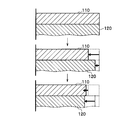
- FIG. 2A is a conceptual diagram illustrating a mechanism of generation of residual stress due to thermal stress, and is a diagram illustrating a process of deformation accompanying cooling.
- FIG. 2B is a conceptual diagram illustrating a mechanism of generation of residual stress due to thermal stress, and is a diagram illustrating residual stress after plastic deformation.
- the structure volume change of the surface vicinity of steel materials is typically shown.
- Reference numeral 110 denotes a surface structure existing on the surface side of the steel material
- reference numeral 120 denotes an internal structure existing on the inner side.
- the thermal stress generated in quenching shows a distribution in which the heat shrinkage of the cooled steel material changes with time in the depth direction due to the cooling rate difference in the depth direction of the steel material.
- the steel material is heated up to the transformation temperature or more, and as shown in the upper part of FIG. 2A, stress and strain are not substantially recognized in the surface structure 110 and the internal structure 120. Yes.
- the cooling of the steel material proceeds from the surface structure 110 side to the internal structure 120 over time, and a cooling rate difference is generated between the surface side and the internal side. Therefore, as shown in the middle part of FIG. 2A, the surface tissue 110 side is more thermally contracted than the internal tissue 120 side where heat conduction is delayed, and the internal tissue 120 side where heat conduction is delayed is contracted and deformed on the surface tissue 110 side. Dragging to plastically deform and shrink.
- the solidification of the metal structure is stopped on the surface structure 110 side and the dimensional change is eliminated, whereas the internal structure 120 side where the heat conduction is delayed. In this case, it is still cooled and heat shrinkage proceeds. And the internal structure
- the residual stress shows a distribution in the depth direction in which the compressive residual stress is dominant when the surface tissue 110 side receives the contraction force by the internal tissue 120.
- the internal structure 120 since the internal structure 120 receives an extension force from the surface structure 110, the internal structure 120 exhibits a distribution in the depth direction in which the tensile residual stress is dominant.
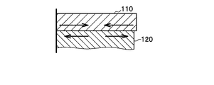
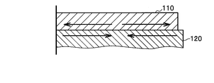
- FIG. 3A is a conceptual diagram illustrating a mechanism of generation of residual stress due to transformation stress, and is a diagram illustrating a process of deformation accompanying martensitic transformation.
- FIG. 3B is a conceptual diagram illustrating a mechanism of generation of residual stress by transformation stress, and is a diagram illustrating residual stress after plastic deformation.
- the structure volume change of the surface vicinity of steel materials is typically shown like FIG. 2A and FIG. 2B.
- Reference numeral 110 denotes a surface structure existing on the surface side of the steel material
- reference numeral 120 denotes an internal structure existing on the inner side.
- the transformation stress of the metal structure generated during quenching is the distribution in the direction opposite to the thermal stress due to the expansion of the cooled steel due to the martensitic transformation constrained by the difference in the cooling rate in the depth direction of the steel. Indicates.
- the cooling of the steel material proceeds from the surface structure 110 side, and the surface side and the internal structure A cooling rate difference occurs between the two sides. Therefore, as shown in the middle part of FIG. 3A, the surface texture 110 side falls below the martensite transformation start temperature (Ms) earlier than the internal structure 120 side where heat conduction is delayed, and expands greatly with the martensitic transformation.
- Ms martensite transformation start temperature
- the internal tissue 120 side where heat conduction is delayed is pulled and plastically deformed by being dragged toward the surface tissue 110 side.
- the surface texture 110 side is below the martensite transformation end temperature (Mf) before the internal structure 120 side where heat conduction is delayed, and the metal Tissue volume changes subside.
- the internal structure 120 side where the heat conduction is delayed still causes expansion due to the martensitic transformation in a temperature range from the martensitic transformation start temperature (Ms) to the martensitic transformation end temperature (Mf).
- the internal structure 120 that continues to expand ends plastic deformation while constraining the surface structure 110 in the tensile direction. As a result, as shown in FIG.
- the generated residual stress is pulled by the expansion of the internal tissue 120 by the surface texture 110, and the tensile residual stress becomes more dominant toward the surface texture 110 side.
- the internal tissue 120 receives compressive force from the surface tissue 110, and the compressive residual stress becomes more dominant toward the internal tissue 120 side.
- the transformation stress has a distribution opposite to the thermal stress.
- the quenching depth is sufficiently deep and the main phase of the metal structure is made martensite up to the central part of the cross section. Therefore, there is little room for reducing transformation stress. Therefore, in order to make the thermal stress superior to the transformation stress, it is preferable to select a quenching condition with a fast cooling rate suitable for generating the thermal stress. Therefore, when the vehicle stabilizer 1 is manufactured, quenching is performed with a medium having a heat transfer coefficient equivalent to or close to that of water.
- manganese boron steel (Mn—B steel) containing Mn and B which has better hardenability than conventional spring steel, is used as the base of the vehicle stabilizer 1. This is because, when the hardenability of the steel material is poor, if quenching with a fast cooling rate is performed, there is a high risk that distortion and cracking will occur.
- the base of the vehicle stabilizer 1 is determined to have a low carbon content of 0.15 mass% or more and 0.39 mass% or less because strength and toughness are required.
- the raw material of the vehicle stabilizer 1 is composed of a steel type having a low carbon content among manganese boron steels. Carbon (C): 0.15 mass% to 0.39 mass%, manganese (Mn ), Boron (boron; B), and iron (Fe).
- C Carbon
- Mn manganese
- B Boron
- Fe iron
- the base body of the vehicle stabilizer 1 is, in mass%, C: 0.15% to 0.39%, Si: 0.05% to 0.40%, Mn: 0.50% to 1 70% or less, B: 0.0005% or more and 0.003% or less as essential elements, P: 0.040% or less, S: 0.040% or less, and optional additive elements include Ni, Cr , Cu, Mo, V, Ti, Nb, Al, N, Ca and Pb, each containing at least one element selected from the group consisting of 1.20% or less, and the balance being Fe and Consists of inevitable impurities. Specifically, Standard American Engineering Standard 15B23 equivalent steel or 15B26 equivalent steel is easily available and preferable.
- the steel bar material used as the raw material of the vehicle stabilizer 1 has a chemical composition that does not contain any additive element, a steel bar material having good hardenability can be obtained at a low material cost. Therefore, the vehicle stabilizer 1 can be manufactured at low cost. it can.
- it is set as the chemical composition containing an arbitrary addition element it will become possible to modify
- the chemical composition containing the optional additive element the balance with respect to the essential element, the optional additive element, and P and S positioned as unavoidable impurities is occupied by Fe and other unavoidable impurities.
- Carbon (C) is a component that contributes to improvement in mechanical strength and hardness. By setting C to 0.15% by mass or more, good mechanical strength and hardness (hardness) can be ensured, and quenching hardness superior to conventional spring steel can be achieved.
- the fatigue strength of the vehicle stabilizer 1 is substantially proportional to the hardness.
- the C content is more preferably 0.18% by mass to 0.35% by mass, and still more preferably 0.20% by mass to 0.26% by mass. Thereby, the mechanical characteristics of the above-described vehicle stabilizer 1 can be further enhanced.
- Silicon (Si) is a component that contributes to improvement of mechanical strength and hardness. Moreover, it is also a component added for the purpose of deoxidation at the time of steelmaking of steel materials. By setting Si to 0.05 mass% or more, good mechanical strength, hardness, corrosion resistance, and sag resistance can be ensured. On the other hand, the fall of toughness and workability can be suppressed by making Si into 0.40 mass% or less.
- the Si content is preferably 0.15% by mass or more and 0.30% by mass or less.
- Manganese (Mn) is a component that contributes to improving hardenability and mechanical strength. Moreover, it is also a component added for the purpose of deoxidation at the time of steelmaking of steel materials. By making Mn 0.50 mass% or more, hardenability can be ensured with good mechanical strength. On the other hand, by setting Mn to 1.70% by mass or less, a decrease in toughness and corrosion resistance due to microsegregation and a decrease in workability can be suppressed.
- the content of Mn is more preferably 0.60% by mass or more and 1.50% by mass or less, and further preferably 0.80% by mass or more and 1.50% by mass or less.
- B Boron
- B is a component that contributes to improving hardenability and mechanical strength.
- B 0.0005 mass% or more and 0.003 mass% or less good hardenability can be ensured.
- toughness and corrosion resistance can be improved by grain boundary strengthening.
- the content of B exceeds 0.003% by mass, the effect of improving hardenability is saturated and the mechanical properties are deteriorated, so the upper limit of the content is limited.
- Phosphorus (P) is an unavoidable impurity that remains from the time of steelmaking. By making P into 0.040 mass% or less, the fall of toughness and corrosion resistance by segregation can be suppressed.
- the content of P is more preferably 0.030% by mass or less.
- S is an unavoidable impurity that remains from the time of steelmaking. By making S into 0.040 mass% or less, the fall of toughness and corrosion resistance by segregation or precipitation of a MnS type inclusion can be suppressed.
- the content of S is more preferably 0.030% by mass or less.
- Nickel (Ni) is a component that contributes to improving corrosion resistance and hardenability. By adding Ni, it is possible to ensure good corrosion resistance and hardenability, and it is possible to reduce corrosion deterioration and quench cracking. On the other hand, even if Ni is excessively contained, the effect of improving the hardenability is saturated and the material cost is also increased. Therefore, the content is preferably 0.30% by mass or less, or intentionally added. It can also be set as the composition which does not.
- Chromium (Cr) is a component that contributes to improving strength, corrosion resistance, and hardenability. By adding Cr, strength, corrosion resistance and hardenability can be improved. On the other hand, if Cr is excessively contained, the toughness and corrosion resistance are reduced due to segregation of carbides, the workability is reduced, and the material cost is also increased. And may be 0.60% by mass or less, or may be a composition not added intentionally.
- Copper (Cu) is a component that contributes to improving hardenability and corrosion resistance. By adding Cu, hardenability and corrosion resistance can be improved. However, since excessive surface embrittlement may occur when Cu is excessively contained, it is preferably 0.30% by mass or less, or a composition that is not intentionally added can be used.
- Molybdenum (Mo) is a component that contributes to improving hardenability, toughness, and corrosion resistance. By adding Mo, hardenability, toughness, and corrosion resistance can be improved. However, since the material cost increases when Mo is excessively contained, it is preferably 0.08% by mass or less, more preferably 0.02% by mass or less, or a composition not intentionally added. It can also be.
- Vanadium (V) is a component that contributes to improvement of toughness and hardness, and prevents boron (B) from being fixed by N by being combined with nitrogen (N). By adding V, toughness and hardness can be improved, and the effect of boron (B) can be effectively expressed.
- the content is preferably 0.30% by mass or less. It can also be set as the composition which is not added automatically.
- Titanium (Ti) is a component that contributes to improvement of strength and corrosion resistance and prevents the fixation of boron (B) by N by combining with nitrogen (N). By adding Ti, the strength and corrosion resistance can be improved, and the effect of boron (B) can be effectively expressed. On the other hand, if Ti is excessively contained, the toughness and corrosion resistance may be lowered due to precipitation of carbonitrides. Therefore, it is preferably 0.05% by mass or less, or a composition not intentionally added. It can also be.
- Niobium (Nb) is a component that contributes to the improvement of strength and toughness and prevents the fixation of boron (B) by N by combining with nitrogen (N). By adding Nb, the strength and toughness can be improved by making the crystal grains fine, and the effect of boron (B) can be effectively expressed. On the other hand, when Nb is contained excessively, the toughness and corrosion resistance may be lowered due to the precipitation of carbonitrides. Therefore, the content is preferably 0.06% by mass or less, or a composition not intentionally added. It can also be.
- Aluminum (Al) is a component that contributes to improvement of toughness and the like and combines with nitrogen (N) to prevent boron (B) from being fixed by N. Moreover, it is also a component added for the purpose of deoxidation at the time of steelmaking of steel materials. By adding Al, the strength and toughness can be improved by making the crystal grains finer, and the effect of boron (B) can be effectively expressed. On the other hand, if Al is contained excessively, the toughness and corrosion resistance may decrease due to precipitation of nitrides and oxides. Therefore, it is preferable to be 0.30% by mass or less, or intentionally added. It can also be set as the composition which does not. This Al means Soluble Al.
- N Nitrogen
- the N content is preferably 0.02% by mass or less.
- Calcium (Ca) is a component that contributes to improvement of machinability. By adding Ca, the machinability of the steel material can be further improved.
- the Al content is preferably 0.40% by mass or less, or can be a composition not intentionally added.
- Pb is a component that contributes to improvement of machinability. By adding Pb, the machinability of the steel material can be further improved.
- the Pb content is preferably 0.40% by mass or less, or may be a composition not intentionally added.
- the vehicle stabilizer 1 has a metal structure in which the main phase is martensite in the base having the above chemical composition. More specifically, 90% or more of the central portion of the cross section of the vehicle stabilizer 1 has a martensite structure, and the substrate has a martensite structure in at least 90% of the metal structure.
- a manganese boron steel material having a low carbon content is used as a base, and therefore, good toughness is achieved in addition to hardness in a martensitic structure as quenched.
- the vehicle stabilizer 1 preferably has a metal structure composed of a single-phase martensite structure. Since manganese boron steel has good hardenability, it is possible to quench the vehicle stabilizer 1 so as to have a substantially martensitic structure by selecting an appropriate cooling rate for quenching. That is, the quality of the vehicle stabilizer 1 can be controlled by manufacturing conditions such as material selection and quenching.
- the metal structure of the vehicle stabilizer 1 is a single-phase low carbon martensite structure, static strength, durability strength, fatigue characteristics, and the like can be improved. Moreover, since it is a single phase, it becomes difficult to form a local battery in a metal structure, and corrosion resistance can be improved.
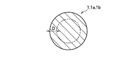
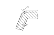
- FIG. 4A is a cross-sectional view of the vehicle stabilizer according to the embodiment of the present invention, and is a cross-sectional view of a torsion part or an arm part of the vehicle stabilizer.
- FIG. 4B is a cross-sectional view of the vehicle stabilizer according to the embodiment of the present invention, and is a vertical cross-sectional view in the vicinity of a bent portion of the vehicle stabilizer.
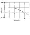
- FIG. 4C is a diagram illustrating a crossing point of residual stress of the vehicle stabilizer according to the embodiment of the present invention, in which the horizontal axis indicates the depth (dimension) D from the surface of the vehicle stabilizer, and the vertical axis indicates the vehicle Indicates the residual stress of the stabilizer.
- FIG. 4A is a cross-sectional view of the vehicle stabilizer according to the embodiment of the present invention, and is a cross-sectional view of a torsion part or an arm part of the vehicle stabilizer.
- FIG. 4B is a cross-sectional view of the vehicle stabilizer according
- 4C schematically shows the crossing point of the residual stress of the vehicle stabilizer 1 and does not represent the actual characteristics of the actual vehicle stabilizer 1.
- 4A and 4B schematically show cross sections of the base body (excluding the paint film) of the torsion part 1a, arm part 1b, and bending part 1c of the vehicle stabilizer 1.
- FIGS. 4A and 4B in the vehicle stabilizer 1, compressive residual stress is applied to a region where the depth (D) from the surface of the substrate is a predetermined distance.
- the crossing point at which the compressive residual stress changes to the tensile residual stress is deeper than 0.8 mm from the surface of the substrate (the tempering and shot peening of the example are not performed (FIG. 9A, tempering and shot peening are not performed).
- FIG. 10B of the comparative example performed). According to the experimental value of FIG. 10B of the comparative example in which tempering and shot peening were performed, the crossing point is about 0.42 mm from the surface of the substrate.
- the comparative example of 0.42 mm is related to the fact that the corrosion pit depth, which is a factor related to corrosion durability, is 0.4 mm at the largest.
- the corrosion pit depth which is a factor related to corrosion durability
- the crossing point is 0 as in the present embodiment. It is desirable to be deeper than .8 mm (see FIG. 9A where the tempering and shot peening are not performed).
- the crossing point (cp) is a depth at which the applied compressive residual stress changes to a tensile residual stress, that is, a depth at which the applied compressive residual stress becomes 0 MPa. means.
- the compressive residual stress from the surface of the base body of the vehicle stabilizer 1 to a depth of 0.8 mm is preferably 150 MPa or more when no load is applied. Further, the compressive residual stress at a depth of 1.0 mm from the surface of the substrate is more preferably 150 MPa or more when no load is applied.
- the compressive residual stress having such a depth can be applied by increasing the cooling rate in quenching. By applying a large compressive residual stress distributed in a deep part, the progress of surface cracks (cracks) can be suppressed, and the fatigue durability of the vehicle stabilizer 1 can be greatly improved.
- the compressive residual stress is applied by quenching, it can be applied to the entire surface layer of the base body of the vehicle stabilizer 1, and the distribution of the compressive residual stress is highly uniform.
- the entire surface layer means the entire region (surface layer) from each point on the entire surface of the substrate to a predetermined depth.
- the point of the present embodiment is that a compressive residual stress of a certain value or more exists above a certain depth that does not reach the depth of the corrosion pit, which is a factor related to corrosion durability. is there.
- the vehicle stabilizer 1 is preferably such that the grain size number G exceeds 8 and more preferably 9 or more with respect to the crystal grain size of the prior austenite grain boundaries.
- the refinement of the crystal grain size can be realized, for example, by lowering the quenching temperature or increasing the content of Mn or an optional additive element.
- the crystal grain size of the prior austenite grain boundaries can be measured in accordance with JIS G 0551.
- the particle size number G can be determined on the basis of a microscope observation image of the as-quenched metal structure, and is preferably obtained as an average value of the particle size numbers of 5 to 10 fields of view.
- the vehicle stabilizer 1 preferably has a Rockwell hardness (HRC) in the range of more than 44.5 and not more than 55.5.
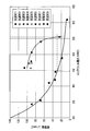
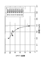
- FIG. 5 is a diagram showing the correlation between Rockwell hardness and impact value of manganese boron steel.
- ⁇ is SUP9N data of a conventional stabilizer
- ⁇ is 15B23 (Standard American Engineering standard) data of an example of this embodiment
- ⁇ is 15B25 of an example of this embodiment ( Standard American Engineering Standard) data.
- Rockwell hardness Such hardness can be realized with necessary toughness if the carbon content is in the range of 0.15% to 0.39% by mass.
- An example of the vehicle stabilizer 1 (see the data of ⁇ and ⁇ in FIG. 5) is equivalent to a conventional spring steel material even in the hardness range of Rockwell hardness exceeding 44.5 and 55.5 or less. Compared with a stabilizer tempered to the hardness of the steel (see the data of ⁇ in FIG. 5), it also has good toughness (for example, a Charpy impact value at room temperature of 30 J / cm 2 or more in HRC44.5). Can do.
- the conventional spring steel SUP9N (see the data of ⁇ in FIG. 5) is an example of a vehicle stabilizer 1 with a Charpy impact value of approximately 35 J / cm 2 . (See the data of 15B23 ⁇ and 15B25 ⁇ in FIG. 5), it can be seen that a Charpy impact value of approximately 90 J / cm 2 or more is obtained.
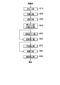
- FIG. 6 is a flowchart showing a method for manufacturing a vehicle stabilizer according to an embodiment of the present invention.
- the stabilizer manufacturing method shown in FIG. 6 includes a processing step S10, a heating step S20, a forming step S30, a quenching step S40, a surface processing step S50, a pretreatment step S60, a preheating step S70, and a coating step. S80 and post-heating process S90 can be included sequentially.
- the surface processing step S50 and the preheating step S70 are not essential steps and can be omitted as will be described later.
- the steel bar material of the above-mentioned low carbon content manganese boron steel is used as the material for the vehicle stabilizer 1.
- the steel bar is a solid metal rod having a solid structure.
- a hot rolled steel material can be applied as the steel bar material.
- the length and diameter of the steel bar can be set to appropriate dimensions according to the desired product shape.
- the diameter of the torsion part 1a is in the range of about 10 mm to about 32 mm.
- This hot-rolled steel material may be subjected to an annealing treatment such as cold rolling or spheroidizing annealing after hot rolling, if necessary.
- the heating temperature of the slab is preferably about 1150 ° C. or higher and 1350 ° C. or lower, and the finishing temperature is preferably 800 ° C. or higher and 1000 ° C. or lower.
- the finishing temperature By setting the finishing temperature to 800 ° C. or higher, the component elements can be appropriately dissolved, and the effect of improving the hardenability by solute boron can be obtained effectively. Further, by setting the finishing temperature to 1000 ° C. or less, it is possible to prevent coarsening of austenite crystal grains, and it is possible to prevent hardness reduction and cracking due to residual austenite.
- the coiling temperature can be, for example, 400 ° C. or higher and 650 ° C. or lower.
- Processing step S10 is a step of forming connecting portions 1d and 1d connected to the stabilizer link 2 (see FIG. 1) by processing both ends of a steel bar material that is a material of the vehicle stabilizer 1.
- the length and diameter of the steel bar can be set to appropriate dimensions according to the desired product shape.
- the form and the forming method of the connecting portions 1d and 1d are not particularly limited.
- the connecting portion 1d by forging the end of the steel bar into a flat shape and punching it by pressing or the like. It is possible to form 1d.
- Heating step S20 is a step of heat-treating the steel bar to perform hot bending.
- a heating method an appropriate method such as heating with a heating furnace, energization heating, high-frequency induction heating or the like can be used, but high-frequency induction heating is preferable.
- the steel bar can be heat-treated while suppressing decarburization and deboronation by rapid heating using high-frequency induction heating. Since the stabilizer 1 for this vehicle employs a manganese boron steel material having a good hardenability as a material, rapid heating using high-frequency induction heating can be applied.
- the forming step S30 is a step of forming a product shape by subjecting the heat-treated steel bar material to a hot (warm) bending process. That is, by bending the bar steel material, the torsion part 1a and the arm part 1b are formed in the bar steel material, and the shape of the bar steel material is shaped into the desired shape of the vehicle stabilizer 1.
- the bending process can be performed at a plurality of locations so that a plurality of bending portions 1c are formed according to a desired product shape, and the torsion portion 1a and the arm portion 1b may be formed by multi-stage bending. it can.
- the quenching step S40 is a step of quenching the steel bar that has been subjected to bending with a medium having a heat transfer coefficient equivalent to or close to that of water. That is, it is a step of quenching at or above the lower critical cooling rate after the steel bar material that has been bent is austenitized.
- the heat transfer coefficient of the medium is preferably within a range of ⁇ 10% with respect to the heat transfer coefficient value of static water or water having flow with respect to the steel bar.
- the quenching temperature, the heating rate, and the quenching holding time can be performed in appropriate ranges.
- the quenching temperature can be 850 ° C. or higher and 1100 ° C. or lower.
- the quenching temperature is preferably set to an austenitizing temperature (AC3) + 100 ° C. or less from the viewpoint of avoiding excessive coarsening of austenite crystal grains and occurrence of quench cracking.
- AC3 austenitizing temperature
- the bar steel material is cooled using a coolant, the metal structure of the bar steel material is martensitic, and compressive residual stress is applied over the entire surface of the bar steel material (base).
- water quenching is a quenching process using water as a coolant.
- the water temperature can be in the temperature range of about 0 ° C. to 100 ° C., preferably 5 ° C. to 40 ° C.
- Aqueous solution quenching is a quenching process using an aqueous solution to which a polymer is added as a coolant.
- polymer for example, various polymers such as polyalkylene glycol and polyvinyl pyrrolidone can be used.
- the polymer concentration is not particularly limited as long as it exhibits the predetermined heat transfer coefficient, and can be adjusted according to the type of polymer, the hardening target of the steel bar used for processing, and the like.
- Salt quenching is a quenching process using an aqueous solution to which salts such as sodium chloride are added as a coolant.
- the salt concentration is not particularly limited as long as it exhibits the predetermined heat transfer coefficient, and can be adjusted according to the degree of quenching of the steel bar to be subjected to the treatment.
- the coolant may or may not be stirred.
- the vehicle stabilizer 1 is a surface processing step S50 or pretreatment without subjecting the steel bar (hereinafter also referred to as a semi-finished product of the vehicle stabilizer 1) that has been quenched in this manner to tempering. It can use for process S60. This is because the use of low carbon manganese boron steel achieves good toughness, hardness, etc. while being quenched.
- the surface processing step S50 is a step of performing shot peening on the hardened steel bar material. Shot peening may be performed either warm or cold, and may be repeated a plurality of times while changing conditions such as particle diameter and projection speed. By performing shot peening, compressive residual stress is applied to the surface of the steel bar, and fatigue strength and wear resistance are improved, and cracks and stress corrosion cracks are prevented. In addition, the steel bar material which has been subjected to quenching may be not subjected to shot peening. That is, as shown in FIG. 6, after the quenching step S40, the pretreatment step S60 can be performed without performing plastic deformation processing such as shot peening for imparting compressive residual stress to the surface layer.
- the pretreatment step S60 is a step of performing surface cleaning and surface treatment in order to perform a coating process on the steel bar. Specifically, it is a step of performing various pretreatments such as a removal treatment for removing oils and fats, foreign matters, and the like on the surface of the steel bar.
- a removal treatment for removing oils and fats, foreign matters, and the like
- the base treatment for example, a coating such as zinc phosphate or iron phosphate can be formed.
- the steel bar is washed with water, and then sequentially subjected to various subsequent treatments after washing with water.
- an appropriate method such as water absorption drying using a draining roller, blow drying, heat drying, or a combination of these can be used.
- the steel bar pretreated in this way can be used for the preheating step S70 or the coating step S80 as shown in FIGS. 2A and 2B.
- the preheating step S70 is a step of preheating the steel bar material.
- the baking time of the paint by post-heating can be shortened, and the coating processing efficiency can be improved.
- the adhesion of the coating film can be improved.
- a heating method an appropriate method such as heating in a heating furnace, energization heating, high-frequency induction heating, or the like can be used.
- energization heating because the heating rate is high and the equipment is simple.
- the preheating temperature is preferably in the range of 180 ° C. or more and 200 ° C.
- the coating step S80 can be performed without performing the preheating step S70 after the pretreatment step S60.
- the painting step S80 is a step of painting a steel bar with a paint.
- a powder paint is preferably used, and for example, a powder paint made of an epoxy resin can be suitably used.
- a coating method for example, a method of spraying a paint so as to form a coating film having a thickness of about 50 ⁇ m or more on the surface of a steel bar material, or a method of immersing in a paint can be used.
- the post-heating step S90 is a step of heating and baking the painted paint.
- heating by a heating furnace is preferable.
- the post-heating temperature is preferably in the range of 180 ° C. or more and 200 ° C. or less, for example. Specifically, for example, post-heating at 180 ° C. for 5 minutes or post-heating at 200 ° C. for 5 minutes is allowed to be applied to the steel bar coated with the paint. This is because, under such heating conditions, it is possible to avoid a decrease in strength and hardness due to heating of the semi-finished product of the vehicle stabilizer 1.
- electrodeposition coating, solvent coating, or the like may be performed as a coating process.
- the vehicle stabilizer 1 can be manufactured through the steps described above. In such a manufacturing method, since tempering is not performed after quenching, there is no need to install a long tempering furnace on the manufacturing line, and the vehicle stabilizer 1 can be manufactured with high productivity on a compact production line. Therefore, it becomes possible to reduce the scale of equipment related to the manufacture of the vehicle stabilizer, and to reduce the operating costs such as the man-hours related to the tempering process and the heating costs associated with the tempering heating.
- the cost of the production line of the vehicle stabilizer 1 can be greatly reduced, and the production cost of the vehicle stabilizer 1 can be reduced. Moreover, construction of the production line of the vehicle stabilizer 1 is facilitated. For example, the production line of the vehicle stabilizer 1 can be easily constructed near the production site of the vehicle manufacturer.
- test materials 1 to 9 having the chemical composition shown in Table 1 below.
- the test materials 1 to 8 are manganese boron steel materials, and the test material 9 is a conventional spring steel material (SUP9A (“SUP9N”)).
- the impact value remains at about 30 J / cm 2 at the practical hardness upper limit (HRC 44.5) in the vehicle stabilizer (Indicated by broken lines in the figure).
- the practical hardness upper limit (HRC44.5) of the test material 9 in the vehicle stabilizer is within the range of HRC44.5 to 56. 5) to HRC56, the impact value exceeds about 30 J / cm 2 , indicating that both mechanical strength and toughness can be achieved.
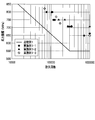
- FIG. 7 is a diagram showing the correlation between the carbon content of manganese boron steel and the impact value. Moreover, as shown in FIG. 7, the impact value in manganese boron steel has a negative correlation with the carbon content (mass%) of each test material, and the toughness mainly depends on the carbon content. I understand that.
- the impact values of the test materials 1 to 8 which are manganese boron steel materials are the impact values (30 J / cm 2 ) recognized in the test material 9, and the carbon content is 0.39 mass%. It exceeds the following range (indicated by a broken line in the figure). Therefore, it is recognized that manganese boron steel having a carbon content of 0.39% by mass or less is suitable as a material for the vehicle stabilizer.
- Example 1-1 to Example 1-3 were manufactured, and the durability was evaluated. Further, as a control, a vehicle stabilizer according to Comparative Example 1 was manufactured and evaluated together.
- Example 1-1 The vehicle stabilizer according to Example 1-1 is tempered by using a specimen 1 shown in Table 1 as a material, and through a forming step S30 for performing cold bending and a quenching step S40 for performing water quenching. Manufactured without.
- the diameter of the vehicle stabilizer was 23 mm.
- Example 1-2 The vehicle stabilizer according to Example 1-2 was manufactured in the same manner as in Example 1-1 except that the material was replaced with the test material 4 shown in Table 1.
- Example 1-3 The vehicle stabilizer according to Example 1-3 was manufactured in the same manner as in Example 1-1 except that the molding step S30 was replaced with hot bending.
- Comparative Example 1 The vehicle stabilizer according to Comparative Example 1 was manufactured by using the test material 9 shown in Table 1 as a material and tempering after oil quenching. The diameter of the vehicle stabilizer was 23 mm.
- FIG. 8 is an SN diagram of the vehicle stabilizer according to the embodiment.
- the durability is improved as compared with the vehicle stabilizer according to Comparative Example 1 indicated by a solid line.
- the fatigue limit of the vehicle stabilizer ( ⁇ ) according to Example 1-1 and the vehicle stabilizer ( ⁇ ) according to Example 1-3 are the same, and hot bending molding and cold bending molding are performed. It is recognized that any of these can be employed.
- vehicle stabilizers according to Examples 2-1 to 2-4 were manufactured, and the surface residual stress was evaluated.
- vehicle stabilizers according to Comparative Examples 2-1 to 2-2 were manufactured and evaluated together.
- Example 2-1 The vehicle stabilizer according to Example 2-1 uses the test material 1 shown in Table 1 as a material, and performs shot peening (surface processing step S50) through a molding step S30 and a quenching step S40 in which water quenching is performed. It was manufactured without any problems.
- Example 2-2 The vehicle stabilizer according to Example 2-2 was manufactured in the same manner as in Example 2-1, except that the material was changed to the test material 4 shown in Table 1.
- Example 2-3 The vehicle stabilizer according to Example 2-3 is manufactured using the specimen 1 shown in Table 1 as a material, and through a molding step S30, a quenching step S40 for performing water quenching, and a surface processing step S50 for performing shot peening. did.
- Example 2-4 The vehicle stabilizer according to Example 2-4 was manufactured in the same manner as in Example 2-3, except that the material was changed to the test material 4 shown in Table 1.
- Comparative Example 2-1 The vehicle stabilizer according to Comparative Example 2-1 was manufactured without using tempering and shot peening after quenching with oil, using the specimen 9 shown in Table 1.
- Comparative Example 2-2 The vehicle stabilizer according to Comparative Example 2-2 was manufactured by using the test material 9 shown in Table 1 as a material and performing tempering and shot peening after oil quenching.
- FIG. 9A is a diagram illustrating a measurement result of the surface residual stress in the vehicle stabilizer according to the example manufactured without performing shot peening.
- FIG. 9B is a diagram illustrating a measurement result of surface residual stress in a vehicle stabilizer according to a comparative example manufactured without performing shot peening.
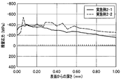
- FIG. 10A is a diagram illustrating a measurement result of the surface residual stress in the vehicle stabilizer according to the example manufactured by performing shot peening.
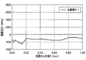
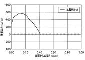
- FIG. 10B is a diagram illustrating a measurement result of the surface residual stress in the vehicle stabilizer according to the comparative example manufactured by performing shot peening.
- the vertical axis represents the residual stress (MPa).
- the ( ⁇ ) side is the (compression) residual stress and the (+) side is the (tensile) residual stress.
- the compressive residual stress is deeply distributed from the surface even though tempering and shot peening are not performed. It can be seen that is generated.
- the crossing point at which the compressive residual stress changes to the tensile residual stress is at a depth of at least 0.8 mm or more from the surface.
- a compressive residual stress of 150 MPa or more (compressive residual stress at no load) is recognized from the surface to a depth of 0.8 mm.
- the surface residual stress of the vehicle stabilizer subjected to the shot peening of the comparative example of FIG. It can be seen that effective compressive residual stress can be applied even if the implementation is omitted.
- the compressive residual stress compressed residual stress at no load
- the compressive residual stress at a depth of 0.42 mm from the surface where the (compressed) residual stress of FIG. 200 MPa or more.
- the compressive residual stress from the surface to a depth of 0.8 mm is 150 MPa or more. Further, the compressive residual stress at a depth of 1.0 mm from the surface (compressive residual stress at no load) reaches 150 MPa or more. In contrast, in Comparative Example 2-1 (see FIG. 9B), the tensile residual stress is distributed, and it is recognized that the generation of surface residual stress due to thermal stress is less likely to be dominant in oil quenching.
- Example 2-3 and Example 2-4 in Example 2-3 and Example 2-4 (see FIG. 10A) subjected to shot peening, Example 2-1 and Example 2-2 (see FIG. 9A) ), It can be seen that the compressive residual stress on the surface side is further enhanced.
- Comparative Example 2-2 in Comparative Example 2-2 (see FIG. 10B), it is recognized that the compressive residual stress on the surface side is enhanced by the oil tempering and shot peening, but the compressive residual stress The distribution remains on the surface side (0.42 mm or less from the surface shown in FIG. 10B).
- the corrosion pit depth which is a factor related to corrosion durability, may be as large as 0.4 mm. Even with the vehicle stabilizer subjected to the shot peening of Comparative Example 2-2, the fatigue strength and Corrosion resistance may be insufficient (see FIG. 10B).
- the surface residual stress of the manganese boron steel material is obtained by using the test materials 1, 2, 6, 7, and 8 having different carbon contents as materials, respectively, through a forming step S30 and a quenching step S40 for performing water quenching, It measured about the stabilizer for vehicles manufactured without performing tempering.
- the diameter of each semi-finished product was set in a range of 21 mm to 25 mm.
- the correlation between the surface residual stress and the diameter indicates that the surface residual stress that can occur at each diameter (diameter) is produced by water quenching (water cooling) and oil quenching (oil cooling). ) And estimated by simulation.
- FIG. 11A is a diagram showing a relationship between the surface residual stress and the carbon content of the steel material in the vehicle stabilizer according to the example.
- FIG. 11B is a diagram illustrating a relationship between the surface residual stress and the diameter of the steel material in the vehicle stabilizer according to the embodiment.
- FIG. 11A it can be seen that the compressive residual stress imparted to the surface by water quenching is larger as the carbon content is lower and decreases as the carbon content is higher. Therefore, when manufacturing a vehicle stabilizer using manganese boron steel with a low carbon content, it can be said that a vehicle stabilizer having high fatigue strength and corrosion resistance can be manufactured even if shot peening is omitted. .
- FIG. 11B tensile residual stress is generated in oil quenching, whereas compressive residual stress is generated in water quenching, and the stress value is in the range of 20 mm to 30 mm in diameter. It can be confirmed that it reaches a sufficient size (about 300 MPa or more).
- a semi-finished product for a vehicle stabilizer (sample 1-1) manufactured using the specimen 1 as a material and undergoing tempering through a molding step S30 and a quenching step S40 in which water quenching is performed. ).
- a vehicle stabilizer semi-finished product (sample 1-2) was used, which was made of the test material 9 which is a conventional spring steel material, subjected to oil quenching and then tempered. The diameter was 14 mm in all cases.
- the corrosion resistance test is a cycle test (CCTI), using each sample masked leaving a range of diameter 10 mm ⁇ length 50 mm as a corroded surface, salt spray for 4 hours at 35 ° C. (NaCl concentration 5%), A cycle consisting of a drying treatment at 60 ° C. for 2 hours and a wet treatment at 50 ° C. and 95% RH for 2 hours was repeated to measure the corrosion weight loss. Corrosion weight loss was determined by dividing the difference between the weight before the test and the weight after the test by the area of the corroded surface.
- CCTI cycle test
- FIG. 12 is a diagram showing the results of the corrosion resistance test.
- Sample 1-2 which was made of a low carbon content manganese boron steel material and subjected to water quenching, a conventional spring steel material was used as a material, and after oil quenching, tempering was performed. It can be seen that the corrosion resistance is improved as compared with Sample 1-2. In Sample 1-2, since troastite or sorbite is produced by tempering, it is recognized that the corrosion rate is increased compared to Sample 1-1 having a low-carbon martensite structure. .
- test spring material 9 which is a conventional spring steel material, oil-quenched, and then tempered semi-finished vehicle stabilizer (sample 2-1)
- the material 1 was used as a material, and a vehicle stabilizer semi-finished product (sample 2-2) manufactured without tempering was provided through a molding step S30 and a quenching step S40 in which water quenching was performed.
- the hardness of sample 2-1 was 42.7 (HRC), and the hardness of sample 2-2 was 45.8 (HRC).
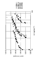
- FIG. 13 is a diagram showing the results of analyzing the progress of fatigue cracks.
- the vertical axis represents the fatigue crack propagation rate da / dN (mm / cycle), and the horizontal axis represents the stress intensity factor range ⁇ K (kgf / mm 3/2 ).
- the plot of ⁇ is Sample 2-1, the plot of ⁇ is Sample 2-2, the plot of ⁇ is Reference Example 1 (reported value of SUP7 (HRC46.5)), and the plot of ⁇ is Reference Example 2 (SUP7 (HRC61.0)). ) (Reported value).
- the fatigue crack propagation rate of Sample 2-2 is about 1/10 to 1/100 of Sample 2-1, and Reference Example 1, Reference Example 2, etc., which are conventional spring steel materials, etc. It can be seen that the toughness is good even when compared with. Further, when the fracture toughness value (Kc) was determined, the Kc of sample 2-2 reached about 1.6 times that of sample 2-1, and it was confirmed that the fatigue durability was also good.
- Embodiments >> 1.
- the type of the medium is not particularly limited.
- it may be water or oil containing ice, an organic solvent, a liquid or solid having a high heat transfer coefficient.
- the phase of the medium is not particularly limited, such as a liquid or a liquid containing a solid.
- the mass% is C: 0.15% or more and 0.39% or less, Si: 0.05% or more and 0.40% or less, Mn: 0.50% 1.70% or less, B: 0.0005% or more and 0.003% or less are contained as essential elements, P: 0.040% or less, S: 0.040% or less, and Ni as optional addition elements , Cr, Cu, Mo, V, Ti, Nb, Al, N, Ca and at least one element selected from the group consisting of Pb can be contained in a range of 1.20% or less, respectively, and the balance, The case of using a steel bar which is an inevitable impurity and Fe has been described as an example.
- the raw material of the vehicle stabilizer 1 is obtained.
- C: 0.15% by mass or more .39 wt% or less, Mn, B, and Fe may be at least including bar steel material.
- mass% C: 0.15% to 0.39%, Mn: 0.50% to 1.70%, B: 0.0005% to 0.003%, and at least Fe A steel bar may be used.
- each configuration may be selected, or each configuration may be appropriately selected and combined.
Landscapes
- Chemical & Material Sciences (AREA)
- Engineering & Computer Science (AREA)
- Mechanical Engineering (AREA)
- Organic Chemistry (AREA)
- Materials Engineering (AREA)
- Metallurgy (AREA)
- Crystallography & Structural Chemistry (AREA)
- Thermal Sciences (AREA)
- Physics & Mathematics (AREA)
- General Engineering & Computer Science (AREA)
- Manufacturing & Machinery (AREA)
- Vehicle Body Suspensions (AREA)
- Heat Treatment Of Articles (AREA)
- Springs (AREA)
- Heat Treatment Of Steel (AREA)
Abstract
Description
近年、戦略的に生産拠点を新設・移設する車両メーカの近くでスタビライザの製造を行うことの要求が高い。そこで、最近はコンパクトなスタビライザの製造ラインが強く求められている。
加えて、従来の長大な焼戻し炉を設置せねばならないことは、新たな製造ラインを作る上で、コスト的にも場所的にも大きな負担となっている。
。また、油焼入れ後の廃油の環境負荷も少なくないため、高い廃棄経費を要しており、スタビライザの生産効率を損なう一因ともなっている。
車両用スタビライザ1の基体は、車幅方向に延びるトーション部1aの両端に対称的に位置する曲げ部1c,1cでそれぞれ屈曲され、左右一対のアーム部1b,1bに連なる略コ字状の形状を有している。
なお、基体とは、所定加工を施された棒鋼で構成される車両用スタビライザ1の本体部分を意味する。
車両用スタビライザ1は、トーション部1aの直径が約10mm~約32mmであり、中実構造の棒状の棒鋼材(金属棒)を用いて形成されるものである。
アーム部1b,1bの先端の各連結部1d、1dは、スタビライザリンク2,2を介して、不図示の車体に固定される左右一対の懸架装置3,3にそれぞれ連結されている。各懸架装置3の車軸部3aには、不図示の車輪が取り付けられる。懸架装置3は、圧縮ばね、オイルダンパを有し、車輪からの衝撃、振動等を減衰して車体に和らげて伝える働きをする。
この構成により、左右の車輪の上下移動により左右の懸架装置3,3にストローク差が生じると、各懸架装置3,3から各アーム部1b,1bに変位による荷重が伝達され、トーション部1aがねじり変形する。そして、トーション部1aには、該ねじり変形を復元しようとする弾性力が生じる。車両用スタビライザ1は、このねじり変形に抗する弾性力によって、車体の左右の傾きを抑えてロール剛性を高め、車両の走行を安定化させる。
車両用スタビライザ1の基体は、炭素(C):0.15質量%以上0.39質量%以下、マンガン(Mn)、ホウ素(ボロン;B)、および鉄(Fe)を少なくとも含む化学組成を有しており、主相がマルテンサイトである金属組織で形成されている。
そこで、車両用スタビライザ1の製造に際しては、水と同等以上または水に近い熱伝達率を有する媒体による焼入れを施すものとする。加えて、車両用スタビライザ1の基体としては、従来用いられているばね鋼と比較して焼入れ性が良好なMn、Bを含むマンガンボロン鋼(Mn-B鋼)を採用する。鋼材の焼入れ性が悪い場合、冷却速度が速い焼入れを行うと、歪や焼割れが発生するおそれが高まるためである。
以上のことから、車両用スタビライザ1の原材は、マンガンボロン鋼のうちでも炭素量が低い鋼種で構成され、炭素(C):0.15質量%以上0.39質量%以下、マンガン(Mn)、ホウ素(ボロン;B)、および鉄(Fe)を少なくとも含む化学組成を有するものとする。炭素量を0.15質量%以上0.39質量%以下の低含有量の範囲とすることによって、焼き入れしたままで良好な靭性が備わり、焼入れ後の置割れが阻止され、耐食性にも優れる車両用スタビライザ1が得られる。後記するように、Mnは、好ましくは0.50%以上1.70%以下、B(ホウ素、ボロン)は、好ましくは0.0005%以上0.003%以下である。
以下、車両用スタビライザ1の原材となる棒鋼材の各成分元素について説明する。
炭素(C)は、機械的強度や硬さの向上等に寄与する成分である。Cを0.15質量%以上とすることで、良好な機械的強度や硬さ(硬度)を確保することができ、従来のばね鋼よりも優れた焼入れ硬さとすることが可能になる。なお、車両用スタビライザ1の疲労強度は、硬度にほぼ比例する。
車両用スタビライザ1は、以上の化学組成を有する基体において、主相がマルテンサイトである金属組織を有している。より具体的には、車両用スタビライザ1の横断面の中心部分の90%以上がマルテンサイト組織を有しており、基体は金属組織の少なくとも90%以上にマルテンサイト組織を有する。
車両用スタビライザ1では、低炭素量のマンガンボロン鋼鋼材を基体としているため、焼入れしたままのマルテンサイト組織において、硬度に加えて良好な靭性が達成されている。
なお、図4A及び図4Bにおいては、車両用スタビライザ1のトーション部1aやアーム部1bや曲げ部1cの基体(塗装塗膜を除く)の断面を模式的に示している。
焼き戻しおよびショットピーニングを行った比較例の図10Bの実験値によれば、クロッシングポイントは、基体の表面から約0.42mmのところにある。比較例の0.42mmというのは、腐食耐久性に関わる要因である腐食ピット深さが、大きいもので0.4mmになることと関係する。
腐食ピットが成長して深くなっていき、圧縮残留応力がなくなり、引っ張り残留応力の領域に到達すると、ピット底を起点として破断が生じる。
この腐食ピットの深さはとりあえず、0.4mmと想定されるが、部品間のバラツキ、様々な環境条件、運転条件などを鑑み、安全性を考えると、本実施形態のようにクロッシングポイントが0.8mmよりも深いところにあることが望ましい(実施例の焼き戻しおよびショットピーニングを行わない図9A参照)。
なお、クロッシングポイント(cp)とは、図4Cに示されるように、付与されている圧縮残留応力が引張残留応力に変わる深さ、すなわち、付与されている圧縮残留応力が0MPaとなる深さを意味する。
また、圧縮残留応力は、焼入れによって付与されるため、車両用スタビライザ1の基体の表層の全域に付与でき、圧縮残留応力の分布の均一性が高い。なお、表層の全域とは、基体の全表面上の各点から所定深さまでの領域(表層)の全体を意味する。
以上の如く、本実施形態(本願発明)は、一定の値以上の圧縮残留応力が腐食耐久性に関わる要因である腐食ピットの深さが及ばない一定の深さ以上に存在することがポイントである。
次に、本実施形態に係る車両用スタビライザの製造方法の一例について説明する。
棒鋼材としては、具体的には、熱間圧延鋼材を適用することができる。棒鋼材の長さ及び径は、所望の製品形状に応じて適宜の寸法とすることが可能である。但し、トーション部1aの直径は約10mm~約32mmの範囲としている。
この熱間圧延鋼材は、必要に応じて、熱間圧延後に冷間圧延や球状化焼鈍等の焼鈍処理が施されていてもよい。また、熱間圧延鋼材に代えて、冷間圧延鋼材を用いることも可能である。熱間圧延を行う場合には、スラブの加熱温度は、1150℃以上1350℃以下程度が好ましく、仕上温度は、800℃以上1000℃以下とすることが好ましい。
媒体の熱伝達率は、棒鋼材に対する静止した水ないし流れを有する水の熱伝達率値に対して±10%以内の範囲であることが好ましい。焼入れ温度、加熱速度及び焼入れ保持時間は、適宜の範囲で行うことが可能である。例えば、焼入れ温度は、850℃以上1100℃以下等とすることができる。但し、焼入れ温度は、オーステナイト結晶粒が過度に粗大化したり、焼割れが発生したりするのを避ける観点から、オーステナイト化温度(AC3)+100℃以下とすることが好ましい。このような加熱を行った後、冷却剤を用いて棒鋼材の冷却を行い、棒鋼材の金属組織をマルテンサイト化させると共に、棒鋼材(基体)の表面の全域にわたって圧縮残留応力を付与する。
除去処理や下地処理等の各処理後には、棒鋼材を水洗し、水洗後に後段の各種処理に順次供する。水洗された棒鋼材の水切りの方法としては、例えば、水切りローラー等を使用した吸水乾燥や、ブロー乾燥や、加熱乾燥や、これらの組み合わせ等による適宜の方法を利用することが可能である。このようにして前処理された棒鋼材は、図2A、図2Bに示すように、予加熱工程S70又は塗装工程S80に供することができる。
このような製造方法では、焼入れの後に焼戻しを施すことが無いため、製造ライン上に長大な焼戻し炉を設置する必要が無く、コンパクトな生産ラインで車両用スタビライザ1を生産性高く製造できる。そのため、車両用スタビライザの製造に関わる設備規模を縮小させたり、焼戻し処理に関わる工数や焼戻し加熱に伴う加熱経費等の操業経費を低減させたりすることが可能になる。
また、車両用スタビライザ1の生産ラインの構築が容易化される。例えば車両メーカーの生産場所近くに車両用スタビライザ1の生産ラインを容易に構築できる。

また、図7に示すように、マンガンボロン鋼鋼材における衝撃値は、各供試材の炭素量(質量%)に対して負の相関を示しており、靭性が主として炭素量に依存していることが分かる。そして、マンガンボロン鋼鋼材である供試材1~供試材8の衝撃値は、供試材9において認められた衝撃値(30J/cm2)の値を、炭素量が0.39質量%以下の範囲で上回っている(図中に破線で示す)。よって、車両用スタビライザの材料としては、炭素量が0.39質量%以下のマンガンボロン鋼が好適であると認められる。
実施例1-1に係る車両用スタビライザは、表1に示す供試材1を材料とし、冷間曲げ加工を施す成形工程S30と、水焼入れを施す焼入れ工程S40とを経て、焼戻しを施すこと無く製造した。なお、車両用スタビライザの径は23mmとした。
実施例1-2に係る車両用スタビライザは、材料を表1に示す供試材4に代えた点を除いて、実施例1-1と同様にして製造した。
実施例1-3に係る車両用スタビライザは、成形工程S30を熱間曲げ加工に代えた点を除いて、実施例1-1と同様にして製造した。
比較例1に係る車両用スタビライザは、表1に示す供試材9を材料とし、油焼入れ後に焼戻しを施して製造した。なお、車両用スタビライザの径は23mmとした。
実施例2-1に係る車両用スタビライザは、表1に示す供試材1を材料とし、成形工程S30と、水焼入れを施す焼入れ工程S40とを経て、ショットピーニング(表面加工工程S50)を施すこと無く製造した。
実施例2-2に係る車両用スタビライザは、材料を表1に示す供試材4に代えた点を除いて、実施例2-1と同様にして製造した。
実施例2-3に係る車両用スタビライザは、表1に示す供試材1を材料とし、成形工程S30と、水焼入れを施す焼入れ工程S40と、ショットピーニングを施す表面加工工程S50とを経て製造した。
実施例2-4に係る車両用スタビライザは、材料を表1に示す供試材4に代えた点を除いて、実施例2-3と同様にして製造した。
比較例2-1に係る車両用スタビライザは、表1に示す供試材9を材料とし、油焼入れ後に焼戻し及びショットピーニングを施すこと無く製造した。
比較例2-2に係る車両用スタビライザは、表1に示す供試材9を材料とし、油焼入れ後に焼戻しとショットピーニングとを施して製造した。
図9Aは、ショットピーニングを施すこと無く製造した実施例に係る車両用スタビライザにおける表面残留応力の測定結果を示す図である。図9Bは、ショットピーニングを施すこと無く製造した比較例に係る車両用スタビライザにおける表面残留応力の測定結果を示す図である。
図10Aは、ショットピーニングを施して製造した実施例に係る車両用スタビライザにおける表面残留応力の測定結果を示す図である。図10Bは、ショットピーニングを施して製造した比較例に係る車両用スタビライザにおける表面残留応力の測定結果を示す図である。
前記したように、腐食耐久性に関わる要因である腐食ピット深さが、大きいもので0.4mmになる場合があり、比較例2-2のショットピーニングを施した車両用スタビライザでも、疲労強度や耐食性が不充分となるおそれがある(図10B参照)。
次に、表面残留応力とマンガンボロン鋼鋼材の炭素量及び径との相関の解析を行った。
次に、低炭素量のマンガンボロン鋼鋼材を材料とし、水焼入れを施して製造される車両用スタビライザの耐食性を評価した。
次に、低炭素量のマンガンボロン鋼鋼材を材料とし、水焼入れを施して製造される車両用スタビライザの疲労き裂の進展性を評価した。
1.前記実施形態では、水と同等以上又は水に近い熱伝達率を有する水性の冷却剤を用いる場合を例示して説明したが、焼き入れ対象を急冷でき、説明した機械的強度、強靭性等の所定の性能が車両用スタビライザ1に得られれば、媒体の種類は特に制限されない。例えば、氷、有機溶剤、熱伝達率が大きい液体や固体などを含む水や油であってよい。なお、媒体とは液体、固体を含む液体などその相は特に限定されない。
1a トーション部
cp クロッシングポイント
S30 成形工程
S40 焼入れ工程
Claims (16)
- 中実構造の金属棒を用いて形成され、左右の車輪の変位を抑えるためのスタビライザであって、
車幅方向に延びて設けられ、ねじり変形するトーション部の直径が10~32mmであり、
C:0.15質量%以上0.39質量%以下、Mn、B、およびFeを少なくとも含む化学組成を有すると共に、その金属組織の90%以上にマルテンサイト組織を有する
ことを特徴とするスタビライザ。 - 中実構造の金属棒を用いて形成され、左右の車輪の変位を抑えるためのスタビライザであって、
車幅方向に延びて設けられ、ねじり変形するトーション部の直径が10~32mmであり、
C:0.15質量%以上0.39質量%以下、Mn、B、およびFeを少なくとも含む化学組成を有すると共に、主相がマルテンサイトである金属組織を有し、
焼き入れ後に焼き戻しまたはショットピーニングの少なくとも何れかが施されていない
ことを特徴とするスタビライザ。 - 圧縮残留応力が表面から少なくとも0.8mmの深さにわたって存在する
ことを特徴とする請求項1または請求項2に記載のスタビライザ。 - 中実構造の金属棒を用いて形成され、左右の車輪の変位を抑えるためのスタビライザであって、
車幅方向に延びて設けられ、ねじり変形するトーション部の直径が10~32mmであり、
C:0.15質量%以上0.39質量%以下、Mn、B、およびFeを少なくとも含む化学組成を有すると共に、主相がマルテンサイトである金属組織を有し、
前記スタビライザの表面近くに圧縮残留応力が付与されており、
前記圧縮残留応力が引張残留応力に変わるクロッシングポイントが、前記表面から0.8mmよりも深いところにある
ことを特徴とするスタビライザ。 - 無負荷時において、前記表面から0.8mmの深さまでの圧縮残留応力が、150MPa以上ある
ことを特徴とする請求項4に記載のスタビライザ。 - ロックウェル硬さ(HRC)が44.5以上、かつ、室温におけるシャルピー衝撃値が30J/cm2以上である
ことを特徴とする請求項1、請求項2、請求項4、および請求項5のうちのいずれか一項に記載のスタビライザ。 - 前記スタビライザは、金属組織の90%以上にマルテンサイト組織を有する
ことを特徴とする請求項2、請求項4、および請求項5のうちのいずれか一項に記載のスタビライザ。 - 前記スタビライザは、焼き戻しおよびショットピーニングが施されていない
ことを特徴とする請求項1、請求項4、および請求項5のうちのいずれか一項に記載のスタビライザ。 - 前記スタビライザは、焼き戻しは施されず、かつ、ショットピーニングが施されている
ことを特徴とする請求項1、請求項4、および請求項5のうちのいずれか一項に記載のスタビライザ。 - 質量%で、C:0.15%以上0.39%以下、Mn:0.50%以上1.70%以下、B:0.0005%以上0.003%以下、およびFeを少なくとも含む化学組成を有する
ことを特徴とする請求項1、請求項2、請求項4、および請求項5のうちのいずれか一項に記載のスタビライザ。 - 質量%で、C:0.15%以上0.39%以下、Si:0.05%以上0.40%以下、Mn:0.50%以上1.70%以下、B:0.0005%以上0.003%以下を必須元素として含有し、P:0.040%以下、S:0.040%以下であり、任意添加元素として、Ni、Cr、Cu、Mo、V、Ti、Nb、Al、N、Ca及びPbからなる群より選択される少なくとも一種以上の元素をそれぞれ1.20%以下の範囲で含有し得ると共に、残部に、Feと不可避的不純物を含む
ことを特徴とする請求項1、請求項2、請求項4、および請求項5のうちのいずれか一項に記載のスタビライザ。 - 前記スタビライザは、Standard American Engineering 規格の15B23相当鋼または15B26相当鋼を用いて形成される
ことを特徴とする請求項1、請求項2、請求項4、および請求項5のうちのいずれか一項に記載のスタビライザ。 - 前記スタビライザは、
水と同等以上または水に近い熱伝達率を有する媒体による焼入れが施されている
ことを特徴とする請求項1、請求項2、請求項4、および請求項5のうちのいずれか一項に記載のスタビライザ。 - 前記媒体は、水である
ことを特徴とする請求項13に記載のスタビライザ。 - 前記スタビライザは、
曲げ加工が施されオーステナイト化後、下部臨界冷却速度以上で焼入れが施されている
ことを特徴とする請求項1、請求項2、請求項4、および請求項5のうちのいずれか一項に記載のスタビライザ - 前記焼入れは、気体または液体を用いて行われている
ことを特徴とする請求項15に記載のスタビライザ。
Priority Applications (5)
| Application Number | Priority Date | Filing Date | Title |
|---|---|---|---|
| US15/534,472 US11111554B2 (en) | 2014-12-08 | 2015-12-04 | Stabilizer |
| CN201580066786.XA CN107107701B (zh) | 2014-12-08 | 2015-12-04 | 稳定器 |
| MX2017007473A MX2017007473A (es) | 2014-12-08 | 2015-12-04 | Estabilizador. |
| KR1020177015540A KR101923126B1 (ko) | 2014-12-08 | 2015-12-04 | 스태빌라이저 |
| EP15868473.8A EP3231644B1 (en) | 2014-12-08 | 2015-12-04 | Stabilizer |
Applications Claiming Priority (2)
| Application Number | Priority Date | Filing Date | Title |
|---|---|---|---|
| JP2014248328A JP6053746B2 (ja) | 2014-12-08 | 2014-12-08 | スタビライザ |
| JP2014-248328 | 2014-12-08 |
Publications (1)
| Publication Number | Publication Date |
|---|---|
| WO2016093183A1 true WO2016093183A1 (ja) | 2016-06-16 |
Family
ID=56107368
Family Applications (1)
| Application Number | Title | Priority Date | Filing Date |
|---|---|---|---|
| PCT/JP2015/084217 Ceased WO2016093183A1 (ja) | 2014-12-08 | 2015-12-04 | スタビライザ |
Country Status (7)
| Country | Link |
|---|---|
| US (1) | US11111554B2 (ja) |
| EP (1) | EP3231644B1 (ja) |
| JP (1) | JP6053746B2 (ja) |
| KR (1) | KR101923126B1 (ja) |
| CN (1) | CN107107701B (ja) |
| MX (1) | MX2017007473A (ja) |
| WO (1) | WO2016093183A1 (ja) |
Families Citing this family (7)
| Publication number | Priority date | Publication date | Assignee | Title |
|---|---|---|---|---|
| DE102017104089A1 (de) * | 2016-03-14 | 2017-09-14 | Ksm Castings Group Gmbh | Verfahren zum Herstellen eines wärmebehandelten, mit einem Radlager versehenen Radträgers |
| EP3653414B1 (en) * | 2017-07-14 | 2023-06-28 | NHK Spring Co., Ltd. | Vehicle stabilizer, and shot peening jig with stabilizers |
| JP7154043B2 (ja) | 2018-06-12 | 2022-10-17 | 日本発條株式会社 | スタビライザ |
| JP6839732B2 (ja) * | 2019-07-08 | 2021-03-10 | 日本発條株式会社 | スタビライザ、およびスタビライザの製造方法 |
| CN111270168A (zh) * | 2020-03-24 | 2020-06-12 | 马鞍山钢铁股份有限公司 | 一种含铌城轨地铁用车轴及其热处理工艺 |
| KR102921730B1 (ko) * | 2022-10-31 | 2026-02-03 | 현대제철 주식회사 | 쾌삭형 탄소강, 그 제조방법 및 쾌삭형 탄소강 부품의 제조방법 |
| KR102811824B1 (ko) * | 2022-10-31 | 2025-05-26 | 현대제철 주식회사 | 보론강 부품의 제조방법 |
Citations (5)
| Publication number | Priority date | Publication date | Assignee | Title |
|---|---|---|---|---|
| JP2000017390A (ja) * | 1998-06-30 | 2000-01-18 | Toa Steel Co Ltd | 高強度冷間成形非調質緩衝・復元機構部材用鋼材 |
| JP2006089785A (ja) * | 2004-09-22 | 2006-04-06 | Jfe Bars & Shapes Corp | 靭性に優れた高強度スタビライザ用鋼およびスタビライザの製造方法 |
| JP2010185109A (ja) * | 2009-02-12 | 2010-08-26 | Jfe Bars & Shapes Corp | 耐食性と低温靭性に優れた車両用高強度スタビライザ用鋼及びその製造方法とスタビライザ |
| WO2011111623A1 (ja) * | 2010-03-08 | 2011-09-15 | 愛知製鋼株式会社 | 中実スタビライザ、中実スタビライザ用鋼材および中実スタビライザの製造方法 |
| JP2012237040A (ja) * | 2011-05-12 | 2012-12-06 | Jfe Bars & Shapes Corp | 車両懸架用ばね部品用鋼、車両懸架用ばね部品およびその製造方法 |
Family Cites Families (15)
| Publication number | Priority date | Publication date | Assignee | Title |
|---|---|---|---|---|
| JPS58188532A (ja) * | 1982-04-28 | 1983-11-04 | Nhk Spring Co Ltd | 中空スタビライザの製造方法 |
| JPS644424A (en) | 1987-06-23 | 1989-01-09 | Kobe Steel Ltd | Manufacture of seam-welded tube for heat treatment excellent in workability |
| JP3409277B2 (ja) | 1998-05-13 | 2003-05-26 | 株式会社神戸製鋼所 | 非調質ばね用圧延線状鋼または棒状鋼 |
| DE10225035B4 (de) | 2002-06-06 | 2004-11-04 | ZF Lemförder Metallwaren AG | Geteilter Stabilisator und Verfahren zur Herstellung einer verzahnten Anbindung des äußeren Drehteils an einen der beiden Stabilisatorteile |
| JP4129203B2 (ja) | 2003-06-09 | 2008-08-06 | 中央発條株式会社 | 高強度スタビライザ |
| JP4406341B2 (ja) | 2004-09-22 | 2010-01-27 | Jfe条鋼株式会社 | 靭性に優れた高強度スタビライザの製造方法 |
| US20060243355A1 (en) | 2005-04-29 | 2006-11-02 | Meritor Suspension System Company, U.S. | Stabilizer bar |
| JP4735315B2 (ja) | 2006-02-15 | 2011-07-27 | Jfeスチール株式会社 | 自動車構造部材用高張力溶接鋼管およびその製造方法 |
| ES2430839T3 (es) | 2006-09-29 | 2013-11-22 | Ezm Edelstahlzieherei Mark Gmbh | Acero de alta resistencia y usos de un acero de este tipo |
| JP5087353B2 (ja) | 2007-09-19 | 2012-12-05 | 三菱製鋼株式会社 | バネ製品製造ライン |
| DE102009047175A1 (de) * | 2009-11-26 | 2011-06-01 | Evonik Degussa Gmbh | Kautschukmischung |
| JP5511451B2 (ja) | 2010-03-16 | 2014-06-04 | 中央発條株式会社 | 自動車用スタビライザの製造方法 |
| JP5550405B2 (ja) | 2010-03-23 | 2014-07-16 | 中央発條株式会社 | ばねの製造方法 |
| JP6232324B2 (ja) | 2014-03-24 | 2017-11-15 | Jfeスチール株式会社 | 高強度で耐食性に優れたスタビライザー用鋼とスタビライザーおよびその製造方法 |
| JP6408933B2 (ja) * | 2014-08-28 | 2018-10-17 | 日本発條株式会社 | 車両用サスペンション部材 |
-
2014
- 2014-12-08 JP JP2014248328A patent/JP6053746B2/ja active Active
-
2015
- 2015-12-04 CN CN201580066786.XA patent/CN107107701B/zh active Active
- 2015-12-04 EP EP15868473.8A patent/EP3231644B1/en active Active
- 2015-12-04 US US15/534,472 patent/US11111554B2/en active Active
- 2015-12-04 MX MX2017007473A patent/MX2017007473A/es unknown
- 2015-12-04 KR KR1020177015540A patent/KR101923126B1/ko active Active
- 2015-12-04 WO PCT/JP2015/084217 patent/WO2016093183A1/ja not_active Ceased
Patent Citations (5)
| Publication number | Priority date | Publication date | Assignee | Title |
|---|---|---|---|---|
| JP2000017390A (ja) * | 1998-06-30 | 2000-01-18 | Toa Steel Co Ltd | 高強度冷間成形非調質緩衝・復元機構部材用鋼材 |
| JP2006089785A (ja) * | 2004-09-22 | 2006-04-06 | Jfe Bars & Shapes Corp | 靭性に優れた高強度スタビライザ用鋼およびスタビライザの製造方法 |
| JP2010185109A (ja) * | 2009-02-12 | 2010-08-26 | Jfe Bars & Shapes Corp | 耐食性と低温靭性に優れた車両用高強度スタビライザ用鋼及びその製造方法とスタビライザ |
| WO2011111623A1 (ja) * | 2010-03-08 | 2011-09-15 | 愛知製鋼株式会社 | 中実スタビライザ、中実スタビライザ用鋼材および中実スタビライザの製造方法 |
| JP2012237040A (ja) * | 2011-05-12 | 2012-12-06 | Jfe Bars & Shapes Corp | 車両懸架用ばね部品用鋼、車両懸架用ばね部品およびその製造方法 |
Non-Patent Citations (1)
| Title |
|---|
| See also references of EP3231644A4 * |
Also Published As
| Publication number | Publication date |
|---|---|
| CN107107701A (zh) | 2017-08-29 |
| KR101923126B1 (ko) | 2018-11-28 |
| EP3231644A4 (en) | 2018-05-23 |
| KR20170095217A (ko) | 2017-08-22 |
| EP3231644A1 (en) | 2017-10-18 |
| JP6053746B2 (ja) | 2016-12-27 |
| US20170349962A1 (en) | 2017-12-07 |
| EP3231644B1 (en) | 2021-08-18 |
| US11111554B2 (en) | 2021-09-07 |
| JP2016107886A (ja) | 2016-06-20 |
| MX2017007473A (es) | 2018-02-01 |
| CN107107701B (zh) | 2021-02-26 |
Similar Documents
| Publication | Publication Date | Title |
|---|---|---|
| JP6110840B2 (ja) | スタビライザの製造方法 | |
| JP6053746B2 (ja) | スタビライザ | |
| JP5463715B2 (ja) | 自動車構造部材用高強度溶接鋼管の製造方法 | |
| JP6306711B2 (ja) | 耐遅れ破壊特性を有するマルテンサイト鋼および製造方法 | |
| CN102782172B (zh) | 实心稳定杆、实心稳定杆用钢材和实心稳定杆的制造方法 | |
| CN105723004A (zh) | 高硬度热轧钢制品和其制造方法 | |
| JP2001355047A (ja) | 冷間加工性と高周波焼入れ性に優れた高炭素鋼管およびその製造方法 | |
| CN101522931B (zh) | 具有优良冷加工性能的高强度和高韧性弹簧用钢线材,生产所述钢线材的方法及通过使用所述钢线材生产弹簧的方法 | |
| CN112840058A (zh) | 具有增强的韧性和腐蚀疲劳性能的弹簧用线材和钢丝、及其各自的制造方法 | |
| JP5647344B2 (ja) | 金型寿命が改善された高強度冷間鍛造用鋼線の製造方法 | |
| JP5125601B2 (ja) | 自動車構造部材用高張力溶接鋼管およびその製造方法 | |
| JP5653022B2 (ja) | 腐食疲労強度に優れるばね用鋼、及びばね | |
| WO2016158408A1 (ja) | 懸架装置用ばねの製造方法及び懸架装置用ばね | |
| JP2005002365A (ja) | 高強度スタビライザ | |
| JP5653020B2 (ja) | 腐食疲労強度に優れるばね用鋼及びばね | |
| JP2020076154A (ja) | 懸架装置用ばねの製造方法 | |
| JP5941439B2 (ja) | コイルばね、およびその製造方法 | |
| JP6282571B2 (ja) | 高強度中空ばね用鋼の製造方法 | |
| CN1894432A (zh) | 用于冷锻的具有优良低温冲击性能的钢丝及其制造方法 | |
| JP5653021B2 (ja) | 腐食疲労強度に優れるばね用鋼、及びばね | |
| WO2024161363A1 (en) | A high-strength hot-rolled wear resistant steel and a method of manufacturing thereof | |
| JPH0672291B2 (ja) | 耐熱性、パテンチング処理性および弁ばね成形後の高温窒化処理特性の優れた弁ばね用高強度鋼線 | |
| JPWO2014196308A1 (ja) | ばね用鋼、ばね及びばねの製造方法 |
Legal Events
| Date | Code | Title | Description |
|---|---|---|---|
| 121 | Ep: the epo has been informed by wipo that ep was designated in this application |
Ref document number: 15868473 Country of ref document: EP Kind code of ref document: A1 |
|
| ENP | Entry into the national phase |
Ref document number: 20177015540 Country of ref document: KR Kind code of ref document: A |
|
| NENP | Non-entry into the national phase |
Ref country code: DE |
|
| WWE | Wipo information: entry into national phase |
Ref document number: 15534472 Country of ref document: US Ref document number: MX/A/2017/007473 Country of ref document: MX |
|
| REEP | Request for entry into the european phase |
Ref document number: 2015868473 Country of ref document: EP |