WO2016098901A1 - Véhicule du type à selle - Google Patents
Véhicule du type à selle Download PDFInfo
- Publication number
- WO2016098901A1 WO2016098901A1 PCT/JP2015/085576 JP2015085576W WO2016098901A1 WO 2016098901 A1 WO2016098901 A1 WO 2016098901A1 JP 2015085576 W JP2015085576 W JP 2015085576W WO 2016098901 A1 WO2016098901 A1 WO 2016098901A1
- Authority
- WO
- WIPO (PCT)
- Prior art keywords
- catalyst
- exhaust
- upstream
- exhaust passage
- downstream
- Prior art date
- Legal status (The legal status is an assumption and is not a legal conclusion. Google has not performed a legal analysis and makes no representation as to the accuracy of the status listed.)
- Ceased
Links
Images





Classifications
-
- F—MECHANICAL ENGINEERING; LIGHTING; HEATING; WEAPONS; BLASTING
- F01—MACHINES OR ENGINES IN GENERAL; ENGINE PLANTS IN GENERAL; STEAM ENGINES
- F01N—GAS-FLOW SILENCERS OR EXHAUST APPARATUS FOR MACHINES OR ENGINES IN GENERAL; GAS-FLOW SILENCERS OR EXHAUST APPARATUS FOR INTERNAL-COMBUSTION ENGINES
- F01N3/00—Exhaust or silencing apparatus having means for purifying, rendering innocuous, or otherwise treating exhaust
- F01N3/08—Exhaust or silencing apparatus having means for purifying, rendering innocuous, or otherwise treating exhaust for rendering innocuous
- F01N3/10—Exhaust or silencing apparatus having means for purifying, rendering innocuous, or otherwise treating exhaust for rendering innocuous by thermal or catalytic conversion of noxious components of exhaust
- F01N3/18—Exhaust or silencing apparatus having means for purifying, rendering innocuous, or otherwise treating exhaust for rendering innocuous by thermal or catalytic conversion of noxious components of exhaust characterised by methods of operation; Control
- F01N3/20—Exhaust or silencing apparatus having means for purifying, rendering innocuous, or otherwise treating exhaust for rendering innocuous by thermal or catalytic conversion of noxious components of exhaust characterised by methods of operation; Control specially adapted for catalytic conversion
-
- B—PERFORMING OPERATIONS; TRANSPORTING
- B62—LAND VEHICLES FOR TRAVELLING OTHERWISE THAN ON RAILS
- B62M—RIDER PROPULSION OF WHEELED VEHICLES OR SLEDGES; POWERED PROPULSION OF SLEDGES OR SINGLE-TRACK CYCLES; TRANSMISSIONS SPECIALLY ADAPTED FOR SUCH VEHICLES
- B62M7/00—Motorcycles characterised by position of motor or engine
- B62M7/02—Motorcycles characterised by position of motor or engine with engine between front and rear wheels
-
- F—MECHANICAL ENGINEERING; LIGHTING; HEATING; WEAPONS; BLASTING
- F01—MACHINES OR ENGINES IN GENERAL; ENGINE PLANTS IN GENERAL; STEAM ENGINES
- F01N—GAS-FLOW SILENCERS OR EXHAUST APPARATUS FOR MACHINES OR ENGINES IN GENERAL; GAS-FLOW SILENCERS OR EXHAUST APPARATUS FOR INTERNAL-COMBUSTION ENGINES
- F01N13/00—Exhaust or silencing apparatus characterised by constructional features
- F01N13/002—Apparatus adapted for particular uses, e.g. for portable devices driven by machines or engines
-
- F—MECHANICAL ENGINEERING; LIGHTING; HEATING; WEAPONS; BLASTING
- F01—MACHINES OR ENGINES IN GENERAL; ENGINE PLANTS IN GENERAL; STEAM ENGINES
- F01N—GAS-FLOW SILENCERS OR EXHAUST APPARATUS FOR MACHINES OR ENGINES IN GENERAL; GAS-FLOW SILENCERS OR EXHAUST APPARATUS FOR INTERNAL-COMBUSTION ENGINES
- F01N13/00—Exhaust or silencing apparatus characterised by constructional features
- F01N13/009—Exhaust or silencing apparatus characterised by constructional features having two or more separate purifying devices arranged in series
- F01N13/0093—Exhaust or silencing apparatus characterised by constructional features having two or more separate purifying devices arranged in series the purifying devices are of the same type
-
- F—MECHANICAL ENGINEERING; LIGHTING; HEATING; WEAPONS; BLASTING
- F01—MACHINES OR ENGINES IN GENERAL; ENGINE PLANTS IN GENERAL; STEAM ENGINES
- F01N—GAS-FLOW SILENCERS OR EXHAUST APPARATUS FOR MACHINES OR ENGINES IN GENERAL; GAS-FLOW SILENCERS OR EXHAUST APPARATUS FOR INTERNAL-COMBUSTION ENGINES
- F01N13/00—Exhaust or silencing apparatus characterised by constructional features
- F01N13/08—Other arrangements or adaptations of exhaust conduits
-
- F—MECHANICAL ENGINEERING; LIGHTING; HEATING; WEAPONS; BLASTING
- F01—MACHINES OR ENGINES IN GENERAL; ENGINE PLANTS IN GENERAL; STEAM ENGINES
- F01N—GAS-FLOW SILENCERS OR EXHAUST APPARATUS FOR MACHINES OR ENGINES IN GENERAL; GAS-FLOW SILENCERS OR EXHAUST APPARATUS FOR INTERNAL-COMBUSTION ENGINES
- F01N13/00—Exhaust or silencing apparatus characterised by constructional features
- F01N13/08—Other arrangements or adaptations of exhaust conduits
- F01N13/10—Other arrangements or adaptations of exhaust conduits of exhaust manifolds
-
- F—MECHANICAL ENGINEERING; LIGHTING; HEATING; WEAPONS; BLASTING
- F01—MACHINES OR ENGINES IN GENERAL; ENGINE PLANTS IN GENERAL; STEAM ENGINES
- F01N—GAS-FLOW SILENCERS OR EXHAUST APPARATUS FOR MACHINES OR ENGINES IN GENERAL; GAS-FLOW SILENCERS OR EXHAUST APPARATUS FOR INTERNAL-COMBUSTION ENGINES
- F01N3/00—Exhaust or silencing apparatus having means for purifying, rendering innocuous, or otherwise treating exhaust
- F01N3/08—Exhaust or silencing apparatus having means for purifying, rendering innocuous, or otherwise treating exhaust for rendering innocuous
- F01N3/10—Exhaust or silencing apparatus having means for purifying, rendering innocuous, or otherwise treating exhaust for rendering innocuous by thermal or catalytic conversion of noxious components of exhaust
- F01N3/101—Three-way catalysts
-
- F—MECHANICAL ENGINEERING; LIGHTING; HEATING; WEAPONS; BLASTING
- F01—MACHINES OR ENGINES IN GENERAL; ENGINE PLANTS IN GENERAL; STEAM ENGINES
- F01N—GAS-FLOW SILENCERS OR EXHAUST APPARATUS FOR MACHINES OR ENGINES IN GENERAL; GAS-FLOW SILENCERS OR EXHAUST APPARATUS FOR INTERNAL-COMBUSTION ENGINES
- F01N3/00—Exhaust or silencing apparatus having means for purifying, rendering innocuous, or otherwise treating exhaust
- F01N3/08—Exhaust or silencing apparatus having means for purifying, rendering innocuous, or otherwise treating exhaust for rendering innocuous
- F01N3/10—Exhaust or silencing apparatus having means for purifying, rendering innocuous, or otherwise treating exhaust for rendering innocuous by thermal or catalytic conversion of noxious components of exhaust
- F01N3/105—General auxiliary catalysts, e.g. upstream or downstream of the main catalyst
-
- F—MECHANICAL ENGINEERING; LIGHTING; HEATING; WEAPONS; BLASTING
- F01—MACHINES OR ENGINES IN GENERAL; ENGINE PLANTS IN GENERAL; STEAM ENGINES
- F01N—GAS-FLOW SILENCERS OR EXHAUST APPARATUS FOR MACHINES OR ENGINES IN GENERAL; GAS-FLOW SILENCERS OR EXHAUST APPARATUS FOR INTERNAL-COMBUSTION ENGINES
- F01N3/00—Exhaust or silencing apparatus having means for purifying, rendering innocuous, or otherwise treating exhaust
- F01N3/08—Exhaust or silencing apparatus having means for purifying, rendering innocuous, or otherwise treating exhaust for rendering innocuous
- F01N3/10—Exhaust or silencing apparatus having means for purifying, rendering innocuous, or otherwise treating exhaust for rendering innocuous by thermal or catalytic conversion of noxious components of exhaust
- F01N3/24—Exhaust or silencing apparatus having means for purifying, rendering innocuous, or otherwise treating exhaust for rendering innocuous by thermal or catalytic conversion of noxious components of exhaust characterised by constructional aspects of converting apparatus
-
- F—MECHANICAL ENGINEERING; LIGHTING; HEATING; WEAPONS; BLASTING
- F01—MACHINES OR ENGINES IN GENERAL; ENGINE PLANTS IN GENERAL; STEAM ENGINES
- F01N—GAS-FLOW SILENCERS OR EXHAUST APPARATUS FOR MACHINES OR ENGINES IN GENERAL; GAS-FLOW SILENCERS OR EXHAUST APPARATUS FOR INTERNAL-COMBUSTION ENGINES
- F01N3/00—Exhaust or silencing apparatus having means for purifying, rendering innocuous, or otherwise treating exhaust
- F01N3/08—Exhaust or silencing apparatus having means for purifying, rendering innocuous, or otherwise treating exhaust for rendering innocuous
- F01N3/10—Exhaust or silencing apparatus having means for purifying, rendering innocuous, or otherwise treating exhaust for rendering innocuous by thermal or catalytic conversion of noxious components of exhaust
- F01N3/24—Exhaust or silencing apparatus having means for purifying, rendering innocuous, or otherwise treating exhaust for rendering innocuous by thermal or catalytic conversion of noxious components of exhaust characterised by constructional aspects of converting apparatus
- F01N3/28—Construction of catalytic reactors
-
- F—MECHANICAL ENGINEERING; LIGHTING; HEATING; WEAPONS; BLASTING
- F01—MACHINES OR ENGINES IN GENERAL; ENGINE PLANTS IN GENERAL; STEAM ENGINES
- F01N—GAS-FLOW SILENCERS OR EXHAUST APPARATUS FOR MACHINES OR ENGINES IN GENERAL; GAS-FLOW SILENCERS OR EXHAUST APPARATUS FOR INTERNAL-COMBUSTION ENGINES
- F01N13/00—Exhaust or silencing apparatus characterised by constructional features
- F01N13/14—Exhaust or silencing apparatus characterised by constructional features having thermal insulation
- F01N13/141—Double-walled exhaust pipes or housings
-
- F—MECHANICAL ENGINEERING; LIGHTING; HEATING; WEAPONS; BLASTING
- F01—MACHINES OR ENGINES IN GENERAL; ENGINE PLANTS IN GENERAL; STEAM ENGINES
- F01N—GAS-FLOW SILENCERS OR EXHAUST APPARATUS FOR MACHINES OR ENGINES IN GENERAL; GAS-FLOW SILENCERS OR EXHAUST APPARATUS FOR INTERNAL-COMBUSTION ENGINES
- F01N13/00—Exhaust or silencing apparatus characterised by constructional features
- F01N13/14—Exhaust or silencing apparatus characterised by constructional features having thermal insulation
- F01N13/141—Double-walled exhaust pipes or housings
- F01N13/143—Double-walled exhaust pipes or housings with air filling the space between both walls
-
- F—MECHANICAL ENGINEERING; LIGHTING; HEATING; WEAPONS; BLASTING
- F01—MACHINES OR ENGINES IN GENERAL; ENGINE PLANTS IN GENERAL; STEAM ENGINES
- F01N—GAS-FLOW SILENCERS OR EXHAUST APPARATUS FOR MACHINES OR ENGINES IN GENERAL; GAS-FLOW SILENCERS OR EXHAUST APPARATUS FOR INTERNAL-COMBUSTION ENGINES
- F01N2240/00—Combination or association of two or more different exhaust treating devices, or of at least one such device with an auxiliary device, not covered by indexing codes F01N2230/00 or F01N2250/00, one of the devices being
- F01N2240/20—Combination or association of two or more different exhaust treating devices, or of at least one such device with an auxiliary device, not covered by indexing codes F01N2230/00 or F01N2250/00, one of the devices being a flow director or deflector
-
- F—MECHANICAL ENGINEERING; LIGHTING; HEATING; WEAPONS; BLASTING
- F01—MACHINES OR ENGINES IN GENERAL; ENGINE PLANTS IN GENERAL; STEAM ENGINES
- F01N—GAS-FLOW SILENCERS OR EXHAUST APPARATUS FOR MACHINES OR ENGINES IN GENERAL; GAS-FLOW SILENCERS OR EXHAUST APPARATUS FOR INTERNAL-COMBUSTION ENGINES
- F01N2260/00—Exhaust treating devices having provisions not otherwise provided for
- F01N2260/08—Exhaust treating devices having provisions not otherwise provided for for preventing heat loss or temperature drop, using other means than layers of heat-insulating material
-
- F—MECHANICAL ENGINEERING; LIGHTING; HEATING; WEAPONS; BLASTING
- F01—MACHINES OR ENGINES IN GENERAL; ENGINE PLANTS IN GENERAL; STEAM ENGINES
- F01N—GAS-FLOW SILENCERS OR EXHAUST APPARATUS FOR MACHINES OR ENGINES IN GENERAL; GAS-FLOW SILENCERS OR EXHAUST APPARATUS FOR INTERNAL-COMBUSTION ENGINES
- F01N2260/00—Exhaust treating devices having provisions not otherwise provided for
- F01N2260/20—Exhaust treating devices having provisions not otherwise provided for for heat or sound protection, e.g. using a shield or specially shaped outer surface of exhaust device
-
- F—MECHANICAL ENGINEERING; LIGHTING; HEATING; WEAPONS; BLASTING
- F01—MACHINES OR ENGINES IN GENERAL; ENGINE PLANTS IN GENERAL; STEAM ENGINES
- F01N—GAS-FLOW SILENCERS OR EXHAUST APPARATUS FOR MACHINES OR ENGINES IN GENERAL; GAS-FLOW SILENCERS OR EXHAUST APPARATUS FOR INTERNAL-COMBUSTION ENGINES
- F01N2590/00—Exhaust or silencing apparatus adapted to particular use, e.g. for military applications, airplanes, submarines
- F01N2590/04—Exhaust or silencing apparatus adapted to particular use, e.g. for military applications, airplanes, submarines for motorcycles
-
- F—MECHANICAL ENGINEERING; LIGHTING; HEATING; WEAPONS; BLASTING
- F02—COMBUSTION ENGINES; HOT-GAS OR COMBUSTION-PRODUCT ENGINE PLANTS
- F02B—INTERNAL-COMBUSTION PISTON ENGINES; COMBUSTION ENGINES IN GENERAL
- F02B61/00—Adaptations of engines for driving vehicles or for driving propellers; Combinations of engines with gearing
- F02B61/02—Adaptations of engines for driving vehicles or for driving propellers; Combinations of engines with gearing for driving cycles
-
- Y—GENERAL TAGGING OF NEW TECHNOLOGICAL DEVELOPMENTS; GENERAL TAGGING OF CROSS-SECTIONAL TECHNOLOGIES SPANNING OVER SEVERAL SECTIONS OF THE IPC; TECHNICAL SUBJECTS COVERED BY FORMER USPC CROSS-REFERENCE ART COLLECTIONS [XRACs] AND DIGESTS
- Y02—TECHNOLOGIES OR APPLICATIONS FOR MITIGATION OR ADAPTATION AGAINST CLIMATE CHANGE
- Y02A—TECHNOLOGIES FOR ADAPTATION TO CLIMATE CHANGE
- Y02A50/00—TECHNOLOGIES FOR ADAPTATION TO CLIMATE CHANGE in human health protection, e.g. against extreme weather
- Y02A50/20—Air quality improvement or preservation, e.g. vehicle emission control or emission reduction by using catalytic converters
-
- Y—GENERAL TAGGING OF NEW TECHNOLOGICAL DEVELOPMENTS; GENERAL TAGGING OF CROSS-SECTIONAL TECHNOLOGIES SPANNING OVER SEVERAL SECTIONS OF THE IPC; TECHNICAL SUBJECTS COVERED BY FORMER USPC CROSS-REFERENCE ART COLLECTIONS [XRACs] AND DIGESTS
- Y02—TECHNOLOGIES OR APPLICATIONS FOR MITIGATION OR ADAPTATION AGAINST CLIMATE CHANGE
- Y02T—CLIMATE CHANGE MITIGATION TECHNOLOGIES RELATED TO TRANSPORTATION
- Y02T10/00—Road transport of goods or passengers
- Y02T10/10—Internal combustion engine [ICE] based vehicles
- Y02T10/12—Improving ICE efficiencies
Definitions
- the present invention relates to a saddle riding type vehicle.
- a straddle-type vehicle including an engine unit having a plurality of combustion chambers.
- the plurality of combustion chambers are formed in the engine body of the engine unit.
- An exhaust passage is connected to the engine body. Exhaust gas discharged from the engine body flows into the exhaust passage. The downstream end of the exhaust passage portion is connected to the catalyst portion.
- a catalyst for purifying exhaust gas is disposed inside the catalyst portion.
- the catalyst part is disposed, for example, below the engine body (for example, Patent Document 1).
- the cross-sectional area of the catalyst part is larger than the cross-sectional area of the exhaust passage part.
- the cross-sectional area is an area of a cross section orthogonal to the flow direction of the exhaust gas.
- An object of the present invention is to provide a straddle-type vehicle capable of ensuring the support strength in the vertical direction of the catalyst unit and suppressing the increase in size of the vehicle in the vertical direction while improving the exhaust gas purification performance by the catalyst. To do.
- the inventor of the present application examined a space for arranging the catalyst portion in order to suppress the vertical size increase of the vehicle accompanying the size increase of the catalyst. As a result, he came up with the idea of using the space between the engine body and the front wheel. In other words, the first consideration was to arrange the enlarged catalyst portion in front of the engine body. However, unlike the case where the catalyst portion is disposed below the engine body, when the catalyst portion is disposed in front of the engine body, there is no vehicle body frame around the catalyst portion. Therefore, it is difficult to directly support the catalyst part. Therefore, it seems that it is difficult to secure the support strength of the catalyst portion so that it can withstand the vertical vibration of the catalyst portion.
- the inventors of the present application focused on the point that the engine body has a plurality of combustion chambers.
- An exhaust port connected to the exhaust passage portion is formed on the outer surface of the engine body.
- the number of exhaust ports may be the same as or less than the number of combustion chambers.
- the case where the number of exhaust ports is smaller than the number of combustion chambers is a case where a plurality of exhaust passage portions are gathered inside the engine body.
- the cross-sectional area per exhaust port is large.
- the sum of the cross-sectional areas of the plurality of exhaust ports is large.
- the area of the connection portion between the outer surface of the engine body and the exhaust passage portion is large.
- the arrangement interval of the fixtures such as bolts can be widened. Therefore, if the area of the connection portion is large, the exhaust passage portion can be firmly attached to the engine body.
- the inventor of the present application has realized that the exhaust passage portion can be firmly attached to the engine body if the engine body has a plurality of combustion chambers.
- the inventor of the present application has examined the arrangement of the catalyst part utilizing the exhaust passage part firmly attached to the engine body. It has been found that it is not sufficient to simply connect the catalyst part to the exhaust passage part in order to secure the support strength of the catalyst part in the vertical direction so that it can withstand the vibration in the vertical direction of the catalyst part.
- the linear distance between the exhaust port of the engine body and the catalyst part becomes long. Then, when the vehicle vibrates in the vertical direction, the vertical moment around the exhaust port acting on the catalyst portion increases. For this reason, the catalyst portion is likely to vibrate in the vertical direction.
- the inventor of the present application has come up with the idea of shortening the linear distance between the exhaust port of the engine body and the catalyst part by devising the shape of the exhaust passage part connecting the engine body and the catalyst part. Further, when the catalyst part is simply connected to the exhaust passage part, the distance between the center of the upstream end of the catalyst part and the center of gravity of the catalyst part becomes long when viewed in the vertical direction. Further, when viewed in the vertical direction, the distance between the center of the downstream end of the catalyst portion and the center of gravity of the catalyst portion is increased. Then, when the vehicle vibrates in the vertical direction, the vertical moment around the center of the upstream end or the downstream end of the catalyst portion that acts on the catalyst portion increases.
- the inventors of the present application devised the shape of the exhaust passage portion connected to the upstream end of the catalyst portion to shorten the distance between the center of the upstream end of the catalyst portion and the center of gravity of the catalyst portion when viewed in the vertical direction. I came up with the idea. Also, by devising the shape of the exhaust passage part connected to the downstream end of the catalyst part, the inventors came up with the idea of shortening the distance between the center of the downstream end of the catalyst part and the center of gravity of the catalyst part when viewed in the vertical direction. .
- a straddle-type vehicle is a straddle-type vehicle including a body frame, an engine unit supported by the body frame, and a front wheel portion including at least one front wheel.
- the engine unit has a plurality of cylinder holes adjacent along the left-right direction of the vehicle, and a plurality of combustion chambers partially partitioned by the plurality of cylinder holes, supported by the body frame,
- An engine body disposed behind the front wheel portion in the front-rear direction and having at least one exhaust port communicating with the plurality of combustion chambers formed on a front surface thereof; and the at least one exhaust port of the engine body
- an exhaust device having an atmospheric discharge port that is connected and discharges exhaust gas to the atmosphere.
- the exhaust device has a main catalyst that most purifies the exhaust gas discharged from the plurality of combustion chambers in a plurality of exhaust paths from the plurality of combustion chambers to the atmosphere discharge port, and has a length in the exhaust gas flow direction. Is the same as the flow direction length of the exhaust gas of the main catalyst, and at least a part of the main catalyst is disposed between the engine body and the front wheel portion when viewed in the left-right direction, and the flow direction of the exhaust gas flowing through the inside of the main catalyst.
- the saddle riding type vehicle includes a body frame, an engine unit, and a front wheel portion.
- the left-right direction, the front-rear direction, and the up-down direction are the left-right direction of the vehicle, the front-rear direction of the vehicle, and the up-down direction of the vehicle, respectively.
- the engine unit is supported by the body frame.
- the front wheel portion includes at least one front wheel.
- the engine unit includes an engine body and an exhaust device.
- the engine body has a plurality of cylinder holes and a plurality of combustion chambers. The plurality of cylinder holes are adjacent along the left-right direction.
- the engine body is supported by the body frame.
- the engine body is disposed behind the front wheel portion.
- At least one exhaust port communicating with the plurality of combustion chambers is formed on the front surface of the engine body.
- the exhaust device is connected to at least one exhaust port of the engine body.
- the exhaust device has an atmospheric discharge port for discharging exhaust gas to the atmosphere.
- the exhaust device includes a catalyst portion, an upstream exhaust passage portion, a downstream exhaust passage portion, and a muffler portion.
- the catalyst part has a main catalyst.
- the main catalyst most purifies the exhaust gas discharged from the plurality of combustion chambers in the plurality of exhaust paths from the plurality of combustion chambers to at least one atmospheric discharge port.
- the length of the catalyst part in the exhaust gas flow direction is the same as the length of the main catalyst in the exhaust gas flow direction.
- the muffler part has an atmospheric discharge port.
- the muffler portion is connected to the downstream end of the downstream exhaust passage portion. The muffler part reduces the sound generated by the exhaust gas.
- the catalyst portion is disposed between the engine body and the front wheel portion when viewed in the left-right direction. Further, the catalyst portion is arranged so that the flow direction of the exhaust gas flowing through the inside of the catalyst portion is along the vertical direction. Therefore, the catalyst portion is arranged using an empty space between the front surface of the engine body and the rear surface of the front wheel portion. Therefore, even if the main catalyst is increased in size in order to improve the exhaust purification performance, it is possible to suppress an increase in size in the vertical direction of the vehicle.
- the upstream end of the catalyst part is connected to the downstream end of the upstream exhaust passage part.
- the upstream exhaust passage portion is connected to at least one exhaust port formed in the front surface of the engine body.
- At least one exhaust port communicates with the plurality of combustion chambers. Therefore, the area of the connection portion between the front surface of the engine body and the upstream exhaust passage portion is large. When the area of the connection portion is large, the arrangement interval of the fixtures such as bolts can be widened. Therefore, the upstream exhaust passage portion can be firmly attached to the engine body. Further, the upstream exhaust passage portion has an upstream bent portion. The upstream bent portion changes the flow direction of the exhaust gas flowing through the inside from the direction along the front-rear direction to the direction along the vertical direction. Therefore, the linear distance between the exhaust port of the engine body and the catalyst unit can be shortened. Therefore, when the vertical vibration is applied to the catalyst portion, the vertical moment around the engine body acting on the catalyst portion can be reduced.
- the downstream end of the catalyst part is connected to the upstream end of the downstream exhaust passage part.
- the downstream exhaust passage portion has a downstream bent portion.
- the downstream bent portion changes the flow direction of the exhaust gas flowing through the inside from the direction along the vertical direction to the direction along the front-rear direction.
- the vehicle vibrates in the vertical direction when the vehicle vibrates in the vertical direction, the moment in the vertical direction around the center of the upstream end or the downstream end of the catalyst portion acting on the catalyst portion can be reduced. Therefore, vibrations in the vertical direction of the catalyst part can be suppressed.
- the vertical vibration of the catalyst portion in addition to the upstream exhaust passage portion being firmly attached to the engine body, the vertical vibration of the catalyst portion can be suppressed by the shape of the exhaust passage portion. Therefore, even if the main catalyst is enlarged, the support strength in the vertical direction of the catalyst portion can be secured. Therefore, while ensuring the exhaust purification performance of the main catalyst, it is possible to secure the support strength in the vertical direction of the catalyst portion and to suppress the vertical size increase of the vehicle.
- the straddle-type vehicle of the present invention preferably has the following configuration.
- the engine body is arranged such that center axes of the plurality of cylinder holes are along the vertical direction.
- the engine body is arranged such that the central axes of the plurality of cylinder holes are along the vertical direction.
- the catalyst portion is disposed between the engine body and the front wheel portion, and the flow direction of the exhaust gas flowing inside the catalyst portion is a direction along the vertical direction. Therefore, it is easy to arrange the catalyst unit so that the moment in the vertical direction around the center of the upstream end or the downstream end of the catalyst unit acting on the catalyst unit can be reduced. Therefore, the vibration of the catalyst part in the vertical direction can be further suppressed.
- the support strength in the vertical direction of the catalyst portion can be secured. Therefore, it is possible to secure the support strength in the vertical direction of the catalyst portion while further improving the exhaust purification performance of the main catalyst.
- the straddle-type vehicle of the present invention preferably has the following configuration.
- the engine body has a plurality of exhaust ports communicating with the plurality of combustion chambers on a front surface thereof.
- a plurality of exhaust ports communicating with the plurality of combustion chambers are formed on the front surface of the engine body. Therefore, the total opening area of the exhaust ports is larger than when only one exhaust port communicating with the plurality of combustion chambers is formed on the front surface of the engine body. Therefore, the area of the connection portion between the front surface of the engine body and the upstream exhaust passage portion is larger than when only one exhaust port is formed on the front surface of the engine body. Therefore, the support strength in the vertical direction of the catalyst portion is high. Therefore, even if the main catalyst is further enlarged, the support strength in the vertical direction of the catalyst portion can be ensured. Therefore, it is possible to secure the support strength in the vertical direction of the catalyst portion while further improving the exhaust purification performance of the main catalyst.
- the straddle-type vehicle of the present invention preferably has the following configuration.
- the engine body has a crankshaft having a central axis along the left-right direction.
- the catalyst portion is disposed in front of the front-rear direction with respect to the central axis of the crankshaft.
- the straddle-type vehicle of the present invention preferably has the following configuration.
- the engine main body is provided at a lower portion of the engine main body, connected to a crankcase portion including the crankshaft, and an upper end portion of the crankcase portion, and has the plurality of cylinder holes and the plurality of combustion chambers. And a cylinder portion. At least a part of the catalyst portion is disposed in front of the crankcase portion in the front-rear direction.
- the engine body has a crankcase part and a cylinder part.
- the crankcase part is provided in the lower part of the engine body.
- the crankcase part includes a crankshaft.
- the cylinder part is connected to the upper end part of the crankcase part.
- the cylinder part has a plurality of cylinder holes and a plurality of combustion chambers.
- At least a part of the catalyst part is disposed in front of the crankcase part.
- the catalyst unit so that the moment in the vertical direction around the center of the upstream end or the downstream end of the catalyst unit acting on the catalyst unit can be reduced. Therefore, the vibration of the catalyst part in the vertical direction can be further suppressed. Thereby, even if the main catalyst is further enlarged, the support strength in the vertical direction of the catalyst portion can be secured. Therefore, it is possible to secure the support strength in the vertical direction of the catalyst portion while further improving the exhaust purification performance of the main catalyst.
- the straddle-type vehicle of the present invention preferably has the following configuration. When viewed in the left-right direction, at least a part of the catalyst portion is disposed in front of the front-rear direction on a straight line that is orthogonal to the center axis of the cylinder hole and passes through the center axis of the crankshaft.
- a straight line that is orthogonal to the center axis of the cylinder hole and passes through the center axis of the crankshaft is defined as a straight line L.
- at least a part of the catalyst portion is disposed in front of the straight line L.
- the vibration of the catalyst part in the vertical direction can be further suppressed.
- the support strength in the vertical direction of the catalyst portion can be secured. Therefore, it is possible to secure the support strength in the vertical direction of the catalyst portion while further improving the exhaust purification performance of the main catalyst.
- the straddle-type vehicle of the present invention preferably has the following configuration.
- the upstream exhaust passage portion is formed such that the upstream bent portion changes the flow direction of the exhaust gas flowing inside the upstream exhaust passage portion from a direction along the forward direction to a direction along the downward direction.
- the downstream exhaust passage portion is formed such that the downstream bent portion changes the flow direction of the exhaust gas flowing inside the downstream exhaust passage portion from the direction along the downward direction to the direction along the rear direction.
- the saddle riding type vehicle of the present invention preferably has the following configuration.
- the exhaust device is disposed in at least one of the downstream exhaust passage portion and the muffler portion, and is disposed downstream of the downstream bent portion in the exhaust gas flow direction to purify the exhaust gas.
- the exhaust device has at least one downstream sub-catalyst that purifies the exhaust gas.
- the at least one downstream sub-catalyst is disposed in at least one of the downstream exhaust passage portion and the muffler portion.
- downstream sub-catalyst is disposed downstream of the downstream bent portion in the flow direction of the exhaust gas. That is, the downstream sub-catalyst is not disposed in a portion from the upstream end of the downstream exhaust passage portion to the downstream bent portion. Therefore, even if the downstream sub-catalyst is provided, it is possible to prevent the vertical length of the downstream exhaust passage portion from becoming long. Therefore, even if the downstream sub-catalyst is provided, a separation distance between the downstream exhaust passage portion and the ground can be secured. Therefore, it is possible to further suppress an increase in the size of the vehicle in the vertical direction while improving the exhaust gas purification performance by the catalyst.
- the straddle-type vehicle of the present invention preferably has the following configuration.
- the engine body includes at least one internal exhaust passage portion that connects the plurality of combustion chambers and the at least one exhaust port.
- the exhaust device is disposed in at least one of the at least one internal exhaust passage portion and the upstream exhaust passage portion, and is disposed upstream of the upstream bent portion in the exhaust gas flow direction to purify the exhaust gas.
- At least one upstream sub-catalyst for purifying exhaust gas is provided.
- the engine body includes at least one internal exhaust passage portion.
- the internal exhaust passage section connects the combustion chamber and the exhaust port.
- the exhaust device has at least one upstream sub-catalyst that purifies the exhaust gas.
- At least one upstream sub-catalyst is disposed in at least one internal exhaust passage portion and upstream exhaust passage portion.
- the upstream sub-catalyst is disposed upstream of the upstream bent portion in the flow direction of the exhaust gas. That is, the upstream sub-catalyst is not disposed in the portion from the upstream bent portion to the downstream end of the upstream exhaust passage portion. Therefore, even if the upstream sub-catalyst is provided, it is possible to prevent the upstream exhaust passage portion from being lengthened in the vertical direction. Therefore, even if the upstream sub-catalyst is provided, a separation distance between the upstream exhaust passage portion and the ground can be secured. Therefore, it is possible to further suppress an increase in the size of the vehicle in the vertical direction while improving the exhaust gas purification performance by the catalyst.
- the straddle-type vehicle of the present invention preferably has the following configuration. At least a part of the upstream exhaust passage portion is configured by a multiple tube including an inner tube and at least one outer tube covering the inner tube.
- At least a part of the upstream exhaust passage portion is configured by multiple tubes.
- the multiple tube includes an inner tube and at least one outer tube covering the inner tube.
- the strength of the upstream exhaust passage portion can be improved by forming at least a part of the upstream exhaust passage portion by a multiple pipe.
- the vibration in the vertical direction of the catalyst portion can be further suppressed.
- the support strength in the vertical direction of the catalyst portion can be secured. Therefore, it is possible to secure the support strength in the vertical direction of the catalyst portion while further improving the exhaust purification performance of the main catalyst.
- the straddle-type vehicle of the present invention preferably has the following configuration.
- the catalyst portion houses the main catalyst, and covers a downstream end of the upstream exhaust passage portion, a tubular portion connected to the upstream end of the downstream exhaust passage portion, and a catalyst protector that covers at least a part of the outer surface of the tubular portion. Part.
- the catalyst part has a main catalyst, a cylinder part, and a catalyst protector part.
- the cylinder portion accommodates the main catalyst.
- the cylinder portion is connected to the downstream end of the upstream exhaust passage portion and the upstream end of the downstream exhaust passage portion.
- the catalyst protector portion covers at least a part of the outer surface of the cylindrical portion.
- the straddle-type vehicle of the present invention preferably has the following configuration.
- the engine body has an oil filter at a front portion thereof.
- the exhaust device and the oil filter are configured such that at least a part of the oil filter is exposed when the exhaust device and the oil filter are viewed from the front in the front-rear direction.
- an oil filter is provided at the front of the engine body.
- the exhaust device and the oil filter are viewed from the front, at least a part of the oil filter is exposed. Therefore, it is easy to remove the oil filter from the engine body.
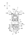
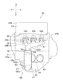
- FIG. 1 is a right side view of a motorcycle according to an embodiment. It is the II-II sectional view taken on the line of FIG. It is a right view of a part of an engine unit. It is a front view of a part of an engine unit. It is a partial schematic diagram of an engine unit. It is a partial schematic diagram of an engine unit. It is sectional drawing of a muffler part. It is a top view of an exhaust apparatus.
- FIG. 10 is a right side view of a part of an engine unit of a first modification.
- FIG. 10 is a right side view of a part of an engine unit of a second modification.
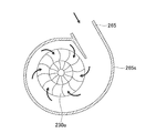
- FIG. 9 is a cross-sectional view of a turbocharger of Modification 2.
- FIG. 10 is a right side view of a turbocharger of Modification 2.
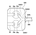
- FIG. 10 is a side view of a turbocharger of a second modification. It is a right view of a part of a modified engine unit. It is sectional drawing of the upstream exhaust passage part of a modification. It is a top view of a part of an engine unit of a modification. It is a partial front view of the engine unit of a modification.
- the front-rear direction is the front-rear direction of the vehicle as viewed from a rider seated on a seat 9 (described later) of the motorcycle 1.
- the left-right direction is the left-right direction of the vehicle when viewed from the rider seated on the seat 9.
- the vehicle left-right direction is the same as the vehicle width direction.
- the arrow F direction and the arrow B direction of each drawing represent the front and the rear
- the arrow L direction and the arrow R direction represent the left side and the right side
- the arrow U direction and the arrow D direction are Represents the top and bottom.
- the motorcycle 1 includes a front wheel portion 2, a rear wheel portion 3, and a vehicle body frame 4.
- the vehicle body frame 4 has a head pipe 4a at the front thereof.
- a steering shaft (not shown) is rotatably inserted into the head pipe 4a.
- the upper end portion of the steering shaft is connected to the handle unit 5.
- An upper end portion of a pair of front forks 6 is fixed to the handle unit 5.
- a lower end portion of the front fork 6 supports the front wheel portion 2.
- the front fork 6 is configured to absorb an impact in the vertical direction.
- the front wheel portion 2 is composed of one front wheel.
- the upper part of the front wheel part 2 is covered with a fender. This fender is not included in the front wheel portion 2.
- the handle unit 5 has one handle bar 12 extending in the left-right direction.
- Grips 13 ⁇ / b> L and 13 ⁇ / b> R are provided at the left and right ends of the handle bar 12.
- the right grip 13R is an accelerator grip that adjusts the output of the engine.
- a display device 14 is attached to the handle bar 12. Although illustration is omitted, the display device 14 displays the vehicle speed, the engine speed, and the like.
- the display device 14 is provided with a warning lamp.
- Various switches are provided on the handle bar 12.
- a pair of swing arms 7 are swingably supported on the body frame 4.
- the rear end portion of the swing arm 7 supports the rear wheel portion 3.
- the rear wheel portion 3 is composed of one rear wheel.
- One end of the rear suspension 8 is attached to a position behind the swing center of each swing arm 7.
- the other end of the rear suspension 8 is attached to the vehicle body frame 4.
- the rear suspension 8 is configured to absorb an impact in the vertical direction. 1 and 2 and FIG. 3 to be described later show a state in which the front fork 6 and the rear suspension 8 have the longest vertical lengths. That is, a state in which the vehicle body frame 4 is at the uppermost position with respect to the front wheel portion 2 and the rear wheel portion 3 is displayed.
- the vehicle body frame 4 supports the seat 9 and the fuel tank 10.
- the fuel tank 10 is disposed in front of the seat 9.
- the vehicle body frame 4 supports the engine unit 11.
- the engine unit 11 may be directly connected to the vehicle body frame 4 or indirectly connected thereto.
- the engine unit 11 is disposed below the fuel tank 10.
- the engine unit 11 is disposed below the upper end of the seat 9.
- the front wheel portion 2 is disposed in front of the engine unit 11.
- the rear wheel portion 3 is disposed behind the engine unit 11 when viewed in the left-right direction.
- the lateral width of the engine unit 11 is larger than the lateral width of the front wheel portion 2.
- the lateral width of the engine unit 11 is larger than the lateral width of the rear wheel portion 3.
- the width in the left-right direction is the maximum length in the left-right direction.
- the vehicle body frame 4 supports a battery (not shown).
- the battery supplies power to a control device (not shown) that controls the engine unit 11 and electronic devices such as various sensors.
- the engine unit 11 includes an engine body 20, a water cooling device 40, and an exhaust device 60. Furthermore, as shown in FIG. 5, the engine unit 11 has an intake device 50. The engine body 20 is connected to the water cooling device 40, the intake device 50, and the exhaust device 60, respectively.
- the engine unit 11 is a three-cylinder engine having three cylinders.
- the engine unit 11 is a 4-stroke engine.
- a 4-stroke engine is an engine that repeats an intake stroke, a compression stroke, a combustion stroke (expansion stroke), and an exhaust stroke. The timing of the combustion stroke in the three cylinders is different.
- FIG. 5 shows only one of the three cylinders of the engine body 20 and omits the remaining two cylinders.
- the engine unit 11 is a water-cooled engine.
- the engine body 20 is configured to be cooled with cooling water.
- High-temperature cooling water that has absorbed the heat of the engine body 20 is supplied from the engine body 20 to the water cooling device 40.
- the water cooling device 40 lowers the temperature of the cooling water supplied from the engine body 20 and returns it to the engine body 20.
- the water cooling device 40 includes a radiator 41, a radiator fan (not shown), and a reservoir tank 42.
- the radiator 41 is disposed in front of the upper portion of the engine body 20.
- the radiator fan is disposed between the engine body 20 and the radiator 41.
- the reservoir tank 42 is disposed in front of the lower part of the engine body 20.
- the reservoir tank 42 is disposed in front of the right part of the engine body 20.
- the reservoir tank 42 may not be disposed in front of the right part of the engine body 20.
- the engine unit 11 has a water pump (not shown) for circulating cooling water.
- the water pump is provided inside the engine body
- the engine body 20 has a crankcase portion 20a and a cylinder portion 20b.
- the crankcase portion 20 a is provided at the lower part of the engine body 20.
- the cylinder part 20 b is provided on the upper part of the engine body 20.
- the cylinder part 20b is connected to the upper end part of the crankcase part 20a.
- the crankcase portion 20a has a crankcase 21 and an oil pan 26.
- the crankcase portion 20 a has a crankshaft 27 that is accommodated in the crankcase 21.
- the crankcase portion 20a includes a transmission, a clutch, a starter motor, and a generator. These are also accommodated in the crankcase 21.
- a central axis Cr of the crankshaft 27 is referred to as a crank axis Cr.
- the crank axis Cr is along the left-right direction. More specifically, the crank axis Cr is parallel to the left-right direction.
- the oil pan 26 is provided below the crankcase portion 20a.
- the oil pan 26 is connected to the lower end of the crankcase 21.
- the boundary between the oil pan 26 and the crankcase 21 is substantially straight.
- an extension of the boundary line between the crankcase 21 and the oil pan 26 is defined as a straight line Lp.
- the straight line Lp is along the front-rear direction.
- the straight line Lp is inclined so as to go downward as it goes forward.
- the straight line Lp may be orthogonal to a cylinder axis Cy described later.
- the right part of the oil pan 26 is recessed with respect to the left part of the oil pan 26.
- the right part of the oil pan 26 is located above the left part of the oil pan 26.
- a part of the exhaust device 60 is disposed inside the recess of the oil pan 26.
- Lubricating oil is stored in the oil pan 26.
- the crankcase part 20 a has an oil pump (not shown) that sucks up the lubricating oil stored in the oil pan 26.
- an oil filter 45 and an oil cooler 46 are provided at the front of the crankcase portion 20a.
- the oil cooler 46 is disposed substantially at the center in the left-right direction of the crankcase portion 20a.
- the oil filter 45 is disposed on the left side of the oil cooler 46.
- a plane passing through the center in the left-right direction of the front wheel portion 2 and the rear wheel portion 3 is defined as C0.
- the center in the left-right direction of the front wheel portion 2 and the rear wheel portion 3 is also the center in the left-right direction of the motorcycle 1.
- the center in the left-right direction of the motorcycle 1 is referred to as the center C0 in the left-right direction of the motorcycle 1.
- the oil cooler 46 is disposed at a position overlapping the center C0 in the left-right direction of the motorcycle 1.
- the oil filter 45 is disposed to the left of the center C0 in the left-right direction of the motorcycle 1. As shown in FIG. 3, the oil cooler 46 projects forward from the front surface of the crankcase 21. Similar to the oil cooler 46, the oil filter 45 also projects forward from the front surface of the crankcase 21.
- the oil filter 45 has a built-in filter main body (not shown). The filter body removes foreign substances contained in the lubricating oil.
- the oil filter 45 is detachably attached to the crankcase 21 so that the filter body can be replaced.
- the cylinder portion 20 b includes a cylinder body 22, a cylinder head 23, and a head cover 24.
- the cylinder body 22 is connected to the upper end portion of the crankcase 21.
- the cylinder head 23 is connected to the upper end portion of the cylinder body 22.
- the head cover 24 is connected to the upper end portion of the cylinder head 23.
- the cylinder body 22 is formed with a cylinder hole 22a.
- Three cylinder holes 22 a are formed in the cylinder body 22.
- the three cylinder holes 22a are adjacent to each other in the left-right direction.
- a piston 28 is slidably accommodated in each cylinder hole 22a.
- the three pistons 28 are connected to one crankshaft 27 via three connecting rods 29.
- a cooling passage 22b through which cooling water flows is formed.
- the central axis Cy of the cylinder hole 22a is referred to as a cylinder axis Cy.
- the three cylinder axes Cy are parallel. When viewed in the left-right direction, the three cylinder axes Cy coincide. As shown in FIG. 3, the cylinder axis Cy does not intersect with the crank axis Cr. Note that the cylinder axis Cy may intersect the crank axis Cr.
- the cylinder axis Cy is along the vertical direction. When viewed in the left-right direction, the cylinder axis Cy is inclined in the front-rear direction with respect to the up-down direction.
- the cylinder axis Cy is inclined such that the cylinder portion 20b is inclined forward. That is, the cylinder axis Cy is inclined so as to go forward as it goes upward.
- the tilt angle of the cylinder axis Cy relative to the vertical direction is defined as a tilt angle ⁇ cy.
- the inclination angle ⁇ cy is not limited to the angle shown in FIG.
- the inclination angle ⁇ cy is not less than 0 degrees and not more than 45 degrees.
- a combustion chamber 30 is formed in the cylinder portion 20b.
- Three combustion chambers 30 are formed in the cylinder portion 20b.
- the three combustion chambers 30 are adjacent to each other in the left-right direction.
- Each combustion chamber 30 is formed by the lower surface of the cylinder head 23, the cylinder hole 22 a, and the upper surface of the piston 28. That is, a part of the combustion chamber 30 is partitioned by the inner surface of the cylinder hole 22a.
- a straight line passing through the crank axis Cr and parallel to the vertical direction as seen in the left-right direction is defined as a straight line La1.
- the three combustion chambers 30 are disposed in front of the straight line La1. That is, when viewed in the left-right direction, the three combustion chambers 30 are disposed in front of the crank axis Cr.
- the tip of the spark plug 31 is disposed in the combustion chamber 30.
- the tip of the spark plug 31 generates a spark discharge.
- the air-fuel mixture in the combustion chamber 30 is ignited.
- the air-fuel mixture is an air-fuel mixture.
- the spark plug 31 is connected to the ignition coil 32.
- the ignition coil 32 stores electric power for causing spark discharge of the spark plug 31.
- the ignition plug 31 and the ignition coil 32 constitute an ignition device.
- an internal intake passage portion 33 and an internal exhaust passage portion 34 are formed.
- path part means the structure which forms a path
- the path means a space through which gas or the like passes.
- the internal intake passage portion 33 is connected to the combustion chamber 30.
- the internal intake passage portion 33 is provided for each combustion chamber 30.
- the internal exhaust passage portion 34 is connected to the combustion chamber 30.
- the internal exhaust passage portion 34 is provided for each combustion chamber 30.
- the internal intake passage portion 33 is provided for introducing air into the combustion chamber 30.
- the internal exhaust passage portion 34 is provided to exhaust the exhaust gas generated in the combustion chamber 30 from the combustion chamber 30.
- the combustion chamber intake port 33a and the combustion chamber exhaust port 34a are formed on the surface defining the combustion chamber 30 of the cylinder head 23.
- the combustion chamber intake port 33 a is formed at the downstream end of the internal intake passage portion 33.
- the combustion chamber exhaust port 34 a is formed at the upstream end of the internal exhaust passage portion 34.
- An intake port 33 b and an exhaust port 34 b are formed on the outer surface of the cylinder head 23.
- the intake port 33 b is formed at the upstream end of the internal intake passage portion 33.
- the exhaust port 34 b is formed at the downstream end of the internal exhaust passage portion 34.
- the number of combustion chamber intake ports 33a provided for one combustion chamber 30 may be one or two or more. For each combustion chamber 30, only one intake port 33b is provided.
- the internal intake passage portion 33 is formed in a bifurcated shape.
- the number of combustion chamber exhaust ports 34 a provided for one combustion chamber 30 may be one or two or more.
- only one exhaust port 34b is provided.
- the air inlet 33 b is formed on the front surface of the cylinder head 23.
- the exhaust port 34 b is formed on the front surface of the cylinder head 23.
- the three exhaust ports 34b are adjacent along the left-right direction.
- an intake valve 37 that opens and closes the combustion chamber intake port 33 a is disposed in the internal intake passage portion 33.
- One intake valve 37 is provided for each combustion chamber intake port 33a.
- An exhaust valve 38 that opens and closes the combustion chamber exhaust port 34 a is disposed in the internal exhaust passage portion 34.
- One exhaust valve 38 is provided for each combustion chamber exhaust port 34a.
- the intake valve 37 and the exhaust valve 38 are driven by a valve gear (not shown) housed in the cylinder head 23.
- the valve gear operates in conjunction with the crankshaft 27.
- the valve operating mechanism may have a variable valve timing device.
- a known variable valve timing device is applied.
- the variable valve timing device is configured to change the opening / closing timing of the intake valve and / or the exhaust valve.
- the engine main body 20 has an injector 54.
- the injector 54 is a fuel supply device that supplies fuel to the combustion chamber 30.
- One injector 54 is provided for each combustion chamber 30.
- the injector 54 is arranged so as to inject fuel in the internal intake passage portion 33.
- the injector 54 is connected to the fuel tank 10.
- a fuel pump (not shown) is arranged inside the fuel tank 10. The fuel pump pumps the fuel in the fuel tank 10 toward the injector 54.
- the injector 54 may be arranged to inject fuel in the combustion chamber 30. Further, the injector 54 may be arranged so as to inject fuel in a branch intake passage portion 51 described later of the intake device 50.
- the engine body 20 may include a carburetor instead of the injector 54 as a fuel supply device. The carburetor supplies fuel into the combustion chamber 30 using the negative pressure of the combustion chamber 30.
- the engine body 20 has an engine rotation speed sensor 71 and an engine temperature sensor 72.
- the engine rotation speed sensor 71 detects the rotation speed of the crankshaft 27, that is, the engine rotation speed.
- the engine temperature sensor 72 detects the temperature of the engine body 20. In the present embodiment, the engine temperature sensor 72 indirectly detects the temperature of the cylinder body 22 by detecting the temperature of the cooling water in the cooling passage 22b. The engine temperature sensor 72 may directly detect the temperature of the cylinder body 22.
- the intake device 50 has one intake passage portion 52 and three branched intake passage portions 51.
- the intake passage 52 has an air inlet 52a facing the atmosphere.
- the air inlet 52 a is formed at the upstream end of the intake passage portion 52.
- the intake passage 52 is provided with an air cleaner 53 for purifying air.
- the downstream end of the intake passage portion 52 is connected to the upstream ends of the three branched intake passage portions 51.
- the downstream ends of the three branch intake passage portions 51 are respectively connected to three intake ports 33 b formed on the rear surface of the cylinder head 23.
- the air inlet 52a sucks air from the atmosphere.
- the air flowing into the intake passage portion 52 from the air intake port 52 a is supplied to the engine body 20 through the three branched intake passage portions 51.
- a throttle valve 55 is disposed in the branch intake passage portion 51.
- One throttle valve 55 is provided for each combustion chamber 30.
- the opening degree of the throttle valve 55 is changed by the rider turning the accelerator grip 13R.
- the branch intake passage section 51 is provided with a throttle opening sensor (throttle position sensor) 73, an intake pressure sensor 74, and an intake air temperature sensor 75.
- the throttle opening sensor 73 outputs a signal representing the throttle opening by detecting the position of the throttle valve 55.
- the throttle opening is the opening of the throttle valve 55.
- the intake pressure sensor 74 detects the internal pressure of the branch intake passage portion 51.
- the intake air temperature sensor 75 detects the temperature of the air in the branch intake passage portion 51.
- the exhaust device 60 includes an upstream exhaust passage portion 61, a catalyst portion 62, and a downstream collective exhaust passage portion 63.
- upstream and downstream in the exhaust gas flow direction in the exhaust device 60 and the internal exhaust passage portion 34 are simply referred to as upstream and downstream.
- the upstream exhaust passage portion 61 includes three independent exhaust passage portions 64 and an upstream collective exhaust passage portion 65.
- One independent exhaust passage portion 64 is provided for each combustion chamber 30.
- the downstream collective exhaust passage portion 63 includes a downstream exhaust passage portion 66 and a muffler portion 67.
- the upstream ends of the three independent exhaust passage portions 64 are respectively connected to three exhaust ports 34 b formed on the front surface of the cylinder head 23.
- the downstream ends of the three independent exhaust passage portions 64 are connected to the upstream ends of the upstream collective exhaust passage portion 65.
- the upstream collective exhaust passage portion 65 collects (combines) the exhaust gas discharged from the three independent exhaust passage portions 64.
- the downstream end of the upstream collective exhaust passage portion 65 is connected to the upstream end of the catalyst portion 62.
- the catalyst unit 62 includes a main catalyst 62a that purifies exhaust gas.
- the downstream end of the catalyst portion 62 is connected to the upstream end of the downstream exhaust passage portion 66.
- the downstream end of the downstream exhaust passage portion 66 is connected to the upstream end of the muffler portion 67.
- the muffler part 67 has an atmospheric discharge port 67a facing the atmosphere.
- the exhaust gas discharged from the three exhaust ports 34 b of the engine body 20 passes through the upstream exhaust passage portion 61 and flows into the catalyst portion 62.
- the exhaust gas is purified by passing through the main catalyst 62a and then discharged from the atmospheric discharge port 67a through the downstream collective exhaust passage portion 63.
- the passage portion that combines the internal exhaust passage portion 34 and the independent exhaust passage portion 64 is referred to as an independent exhaust passage portion 68.
- One independent exhaust passage 68 is provided for each combustion chamber 30.
- a path from the combustion chamber 30 to the atmospheric discharge port 67a is referred to as an exhaust path 69.
- the engine unit 11 has three exhaust paths 69.
- the exhaust path 69 is a space through which exhaust gas discharged from one combustion chamber 30 passes.
- the exhaust passage 69 is formed by the independent exhaust passage portion 68, the upstream collective exhaust passage portion 65, the catalyst portion 62, and the downstream collective exhaust passage portion 63.
- the exhaust passage 69 is formed by the internal exhaust passage portion 34, the upstream exhaust passage portion 61, the catalyst portion 62, and the downstream collective exhaust passage portion 63.
- the exhaust device 60 includes an exhaust pipe unit 56, a first collective exhaust pipe 57, a second collective exhaust pipe 58, and a muffler portion 67.
- the exhaust pipe unit 56 includes a first exhaust passage portion 56A, a second exhaust passage portion 56B, and a third exhaust passage portion 56C.
- the first to third exhaust passage portions 56A, 56B, and 56C are arranged in this order from right to left.
- the upstream ends of the first to third exhaust passage portions 56A, 56B, and 56C are connected to the three exhaust ports 34b of the engine body 20, respectively.
- a passage having a substantially circular cross section is formed inside the first to third exhaust passage portions 56A, 56B, and 56C.
- Mounting flange portions 56Af, 56Bf, and 56Cf are provided in the vicinity of the upstream ends of the first to third exhaust passage portions 56A, 56B, and 56C.
- the mounting flange portions 56Af, 56Bf, and 56Cf are formed in a plate shape.
- Bolt holes into which bolts are inserted are formed in the mounting flange portions 56Af, 56Bf, and 56Cf.
- a portion of the first exhaust passage portion 56 ⁇ / b> A upstream from the attachment flange portion 56 ⁇ / b> Af is inserted inside the internal exhaust passage portion 34.
- the mounting flange portions 56Af, 56Bf, and 56Cf are in contact with the outer surface of the engine body 20.
- the mounting flange portions 56Af, 56Bf, and 56Cf are fixed to the outer surface of the engine body 20 by bolts.
- the area of the connection portion between the outer surface of the engine body 20 and the exhaust pipe unit 56 is the sum of the areas of the mounting flange portions 56Af, 56Bf, and 56Cf.
- the downstream ends of the first exhaust passage portion 56A and the third exhaust passage portion 56C are connected in the middle of the second exhaust passage portion 56B.
- the downstream end of the second exhaust passage portion 56 ⁇ / b> B is connected to the upstream end of the first collective exhaust pipe 57.
- the first exhaust passage portion 56A forms an independent exhaust passage portion 64A.
- the independent exhaust passage portion 64A does not include a portion upstream of the mounting flange portion 56Af of the first exhaust passage portion 56A.
- the upstream portion of the portion where the first exhaust passage portion 56A and the third exhaust passage portion 56C are connected forms an independent exhaust passage portion 64B.
- the independent exhaust passage portion 64B does not include a portion upstream of the mounting flange portion 56Bf of the second exhaust passage portion 56B.
- the third exhaust passage portion 56C forms an independent exhaust passage portion 64C.
- the independent exhaust passage portion 64C does not include a portion upstream of the mounting flange portion 56Cf of the third exhaust passage portion 56C.
- the independent exhaust passage portion 64 is a general term for the independent exhaust passage portions 64A, 64B, and 64C.
- the main catalyst 62a is disposed inside the first collecting exhaust pipe 57.
- a portion where the main catalyst 62a of the first collective exhaust pipe 57 is disposed is referred to as a cylindrical portion 62b.
- the catalyst part 62 includes a cylindrical part 62b and a main catalyst 62a.
- the upstream collective exhaust passage portion 65 is formed by a portion of the second exhaust passage portion 56B downstream of the independent exhaust passage portion 64B and a portion of the first collective exhaust pipe 57 upstream of the main catalyst 62a. In FIG. 4, hatching is displayed on the upstream collecting exhaust passage portion 65.
- the downstream end of the first collective exhaust pipe 57 is connected to the upstream end of the second collective exhaust pipe 58.
- the first collective exhaust pipe 57 is a pipe having a substantially circular cross section.
- the second collective exhaust pipe 58 is a pipe having a circular cross section. As shown in FIG. 8, the first collective exhaust pipe 57 is formed by welding two left and right parts.
- the downstream end of the second collective exhaust pipe 58 is connected to the muffler portion 67. Specifically, the downstream end of the second collective exhaust pipe 58 is disposed in the muffler portion 67.
- the downstream exhaust passage portion 66 is formed by a portion of the first collective exhaust pipe 57 downstream from the main catalyst 62 a and the second collective exhaust pipe 58. However, the downstream exhaust passage portion 66 does not include a portion of the second collective exhaust pipe 58 that is disposed inside the muffler portion 67.
- the three independent exhaust passage portions 64 are formed in a straight line when viewed in the left-right direction.
- the upstream collective exhaust passage portion 65 has an upstream bent portion 61a. When viewed in the left-right direction, the upstream bent portion 61a is bent. The upstream bent portion 61a is formed in the second exhaust passage portion 56B. When viewed in the left-right direction, the flow direction of the exhaust gas in the portion upstream of the upstream bent portion 61a of the upstream exhaust passage portion 61 is a front diagonally downward direction. An axis passing through the center of the upstream portion of the upstream exhaust passage portion 61 from the upstream bent portion 61a when viewed in the left-right direction is defined as a central axis C1.
- the direction of the central axis C1 is the flow direction of the exhaust gas at the upstream end of the independent exhaust passage portion 64A.
- the inclination angle ⁇ 1 is not limited to the angle shown in FIG.
- the inclination angle ⁇ 1 is not less than 0 degrees and not more than 45 degrees. Therefore, when viewed in the left-right direction, the central axis C1 is along the front-rear direction. That is, when viewed in the left-right direction, the flow direction of the exhaust gas in the portion upstream of the upstream bent portion 61a of the upstream exhaust passage portion 61 is a direction along the front-rear direction.
- the flow direction of the exhaust gas in the portion downstream of the upstream bent portion 61a of the upstream exhaust passage portion 61 is a rear obliquely downward direction.
- the central axis of the catalyst part 62 is defined as a central axis C2.
- the axis passing through the center of the portion downstream of the upstream bent portion 61a of the upstream exhaust passage portion 61 is coaxial with the center axis C2.
- the inclination angle ⁇ 2 is not limited to the angle shown in FIG.
- the inclination angle ⁇ 2 is not less than 0 degrees and not more than 45 degrees. Accordingly, when viewed in the left-right direction, the central axis C2 is along the up-down direction. That is, when viewed in the left-right direction, the flow direction of the exhaust gas in the portion downstream of the upstream bent portion 61a of the upstream exhaust passage portion 61 is a direction along the vertical direction. When viewed in the left-right direction, the upstream bent portion 61a changes the flow direction of the exhaust gas flowing through the inside from the direction along the front-rear direction to the direction along the up-down direction.
- the upstream bent portion 61a changes the flow direction of the exhaust gas flowing through the upstream bent portion 61a from the direction along the front direction to the direction along the downward direction.
- the upstream bent portion 61a may be formed in the first collective exhaust pipe 57. Further, the upstream bent portion 61 a may be formed in each of the three independent exhaust passage portions 64.
- the central axis C2 of the catalyst unit 62 is along the up-down direction. Further, when viewed in the front-rear direction, the central axis C2 of the catalyst portion 62 is substantially parallel to the up-down direction. Therefore, the central axis C2 of the catalyst part 62 is along the up-down direction. That is, the flow direction of the exhaust gas flowing inside the catalyst unit 62 is a direction along the vertical direction. More specifically, the flow direction of the exhaust gas flowing inside the catalyst unit 62 is a direction along the downward direction. The flow direction of the exhaust gas flowing through the inside of the catalyst part 62 is a rear obliquely downward direction.
- the center of the upstream end of the catalyst unit 62 is located in front of the center of the downstream end of the catalyst unit 62.
- the central axis C2 of the catalyst unit 62 may be inclined in the left-right direction with respect to the up-down direction.
- the downstream exhaust passage portion 66 has a downstream bent portion 66a. When viewed in the left-right direction, the downstream bent portion 66a is bent. The downstream bent portion 66 a is formed at the upstream end portion of the downstream exhaust passage portion 66. When viewed in the left-right direction, the axis passing through the center of the upstream end of the downstream exhaust passage portion 66 is coaxial with the center axis C2. When viewed in the left-right direction, the flow direction of the exhaust gas in the portion downstream of the downstream bent portion 66a of the downstream exhaust passage portion 66 is a direction along the front-rear direction.
- the flow direction of the exhaust gas in the portion downstream of the downstream bent portion 66a of the downstream exhaust passage portion 66 is substantially parallel to the front-rear direction.
- the downstream bent portion 66a changes the flow direction of the exhaust gas flowing through the inside from the direction along the vertical direction to the direction along the front-rear direction. More specifically, the downstream bent portion 66a changes the flow direction of the exhaust gas flowing through the downstream bent portion 66a from the direction along the lower direction to the direction along the rear direction.
- the downstream bent portion 66a may be formed in the middle of the downstream exhaust passage portion 66.
- the vicinity of the downstream end of the upstream collective exhaust passage portion 65 is formed in a tapered shape so that its diameter increases toward the downstream.
- This tapered portion is formed in the first collective exhaust pipe 57. That is, the tapered portion is formed downstream of the upstream bent portion 61a.
- the area of the cross section perpendicular to the flow direction of the exhaust gas in the vicinity of the downstream end of the upstream collective exhaust passage section 65 is defined as a cross sectional area A1.
- a cross section perpendicular to the flow direction of the exhaust gas in the catalyst portion 62 is defined as a cross sectional area A2.
- the cross-sectional area A1 is smaller than the cross-sectional area A2.
- the vicinity of the upstream end of the downstream exhaust passage portion 66 is formed in a tapered shape so that the diameter decreases toward the downstream.
- This taper part is formed in the downstream bending part 66a.
- An area of a cross section perpendicular to the flow direction of the exhaust gas in the vicinity of the upstream end of the downstream exhaust passage section 66 is defined as a cross-sectional area A3.
- the cross-sectional area A3 is smaller than the cross-sectional area A2.
- the muffler unit 67 is a device that reduces noise caused by exhaust gas. As shown in FIG. 8, a bracket 67 b is provided on the upper surface of the muffler portion 67. The bracket 67b is attached to the vehicle body frame 4. That is, the muffler part 67 is supported by the vehicle body frame 4.
- the muffler portion 67 includes an outer cylinder 80 and a tail pipe 85.
- the outer cylinder 80 is formed by welding two left and right parts.
- the muffler portion 67 has four pipes 81 to 84 accommodated in the outer cylinder 80.
- the inside of the outer cylinder 80 is partitioned into three expansion chambers 80a, 80b, and 80c by two separators 86 and 87.
- the first pipe 81 is connected to the downstream end of the second collective exhaust pipe 58.
- a portion of the second collective exhaust pipe 58 inside the outer cylinder 80 is included in the muffler portion 67.
- the first pipe 81 communicates the second collecting exhaust pipe 58 and the central first expansion chamber 80a among the three expansion chambers.
- the second pipe 82 communicates the first expansion chamber 80a with the second expansion chamber 80b behind the first expansion chamber 80a.
- the third pipe 83 communicates the second expansion chamber 80b and the third expansion chamber 80c in front of the first expansion chamber 80a.
- the fourth pipe 84 makes the third expansion chamber 80c communicate with the tail pipe 85 (see FIG. 8).
- the fourth pipe 84 is bent in the second expansion chamber 80b.
- the tail pipe 85 penetrates the right wall of the second expansion chamber 80b.
- the tail pipe 85 is connected to the fourth pipe 84 in the second expansion chamber 80b.
- the opening at the downstream end of the tail pipe 85 is an atmospheric discharge port 67a.
- the exhaust gas discharged from the second collective exhaust pipe 58 includes the first pipe 81, the first expansion chamber 80a, the second pipe 82, the second expansion chamber 80b, the third pipe 83, the third expansion chamber 80c, and the fourth pipe 84.
- the tail pipe 85 passes in this order. And exhaust gas is discharge
- a sound absorbing material such as glass wool may be disposed, but it may not be disposed.
- the internal structure of the muffler part 67 is not limited to the structure shown in FIG.
- the catalyst part 62 includes a main catalyst 62 a and a cylinder part 62 b.
- the cylindrical portion 62 b is connected to the downstream end of the upstream collective exhaust passage portion 65 and the upstream end of the downstream exhaust passage portion 66.
- the cylindrical portion 62b may be integrally formed with a part of the upstream collective exhaust passage portion 65.
- the cylindrical portion 62b may be integrally formed with a part of the downstream exhaust passage portion 66.
- the exhaust device 60 has no catalyst other than the main catalyst 62a.
- the main catalyst 62a most purifies the exhaust gas in the plurality of exhaust paths 69 (see FIG. 5).
- the main catalyst 62a is formed in a cylindrical shape.
- the main catalyst 62a has a porous structure.
- the porous structure means a structure in which a plurality of holes penetrating in the exhaust gas flow direction are formed.
- the main catalyst 62a is a three-way catalyst.
- the three-way catalyst is removed by oxidizing or reducing three substances of hydrocarbon (HC), carbon monoxide (CO), and nitrogen oxide (NOx) in the exhaust gas.
- the three-way catalyst is one type of redox catalyst.
- the main catalyst 62a may be a catalyst that removes any one or two of hydrocarbon, carbon monoxide, and nitrogen oxide.
- the main catalyst 62a may not be a redox catalyst.
- the main catalyst may be an oxidation catalyst that removes harmful substances only by oxidation.
- the main catalyst may be a reduction catalyst that removes harmful substances only by reduction.
- the main catalyst 62a has a base material and a catalytic material attached to the surface of the base material.
- the catalytic material has a support and a noble metal.
- the carrier has a function of attaching a noble metal to the substrate.
- the noble metal has a function of purifying exhaust gas. Examples of the noble metal include platinum, palladium, and rhodium that remove hydrocarbons, carbon monoxide, and nitrogen oxides, respectively.
- the main catalyst 62a may be a metal base catalyst or a ceramic base catalyst.
- the metal base catalyst is a catalyst whose base is made of metal.
- the ceramic base catalyst is a catalyst whose base is made of ceramic.
- the base material of the metal base catalyst is formed, for example, by alternately stacking and winding metal corrugated plates and metal flat plates.
- the base material of the ceramic base catalyst is, for example, a honeycomb structure.
- the central axis C2 of the catalyst part 62 is coaxial with the central axis of the main catalyst 62a.
- the central axis C2 of the catalyst part 62 is the central axis of the cylinder part 62b.
- the length of the catalyst portion 62 in the exhaust gas flow direction is the same as the length of the main catalyst 62a in the exhaust gas flow direction.
- the center of the upstream end of the main catalyst 62a and the center of the upstream end of the catalyst unit 62 are at the same position.
- the center of the downstream end of the main catalyst 62a and the center of the downstream end of the catalyst portion 62 are at the same position.
- the length of the catalyst portion 62 in the exhaust gas flow direction is defined as a length Dc1 (not shown).
- the maximum length in the direction orthogonal to the flow direction of the exhaust gas in the catalyst unit 62 is defined as a length Dc2 (not shown).
- the length Dc1 is longer than the length Dc2.
- the catalyst unit 62 is disposed in front of the engine body 20 when viewed in the left-right direction.
- a plane passing through the uppermost end of the crankcase portion 20a and orthogonal to the vertical direction is defined as a plane Se1.
- a plane passing through the lowest end of the crankcase portion 20a and orthogonal to the vertical direction is defined as a plane Se2.
- the catalyst unit 62 is disposed between the plane Se1 and the plane Se2.
- the catalyst portion 62 is disposed in front of the crankcase portion 20a.
- the lower end of the catalyst unit 62 is disposed above the lower end of the engine body 20.
- the lower end of the engine body 20 is also the lower end of the crankcase portion 20a.
- the lower end of the catalyst unit 62 may be arranged below the lower end of the engine body 20.
- a plane that passes through the leftmost end of the engine body 20 and is orthogonal to the left-right direction is defined as a plane Se3.
- the plane Se3 passes through the leftmost end of the crankcase portion 20a.
- a plane passing through the rightmost end of the engine body 20 and orthogonal to the left-right direction is defined as a plane Se4.
- the plane Se4 passes through the rightmost end of the crankcase portion 20a.
- the catalyst unit 62 is disposed between the plane Se3 and the plane Se4. When viewed from the front, the lower end portion of the catalyst portion 62 does not overlap the engine body 20.
- the lower end portion of the catalyst portion 62 does not overlap the crankcase portion 20a.
- a part of the catalyst unit 62 is disposed in front of the engine body 20.
- a part of the catalyst part 62 is disposed in front of the crankcase part 20a.
- the entire catalyst unit 62 may be disposed in front of the engine body 20. It is preferable that at least a part of the catalyst portion 62 is disposed in front of the engine body 20.
- the whole catalyst part 62 may be arrange
- the catalyst unit 62 When viewed in the left-right direction, the catalyst unit 62 is disposed in front of the straight line La1. That is, the catalyst unit 62 is disposed in front of the crank axis Cr. Further, the catalyst unit 62 is disposed below the crank axis Cr. Note that only a part of the catalyst unit 62 may be disposed below the crank axis Cr. It is preferable that at least a part of the catalyst unit 62 is disposed below the crank axis Cr. When viewed in the left-right direction, the catalyst unit 62 is disposed in front of the cylinder axis Cy.
- a straight line La2 is a straight line perpendicular to the cylinder axis Cy and passing through the crank axis Cr when viewed in the left-right direction.
- a part of the catalyst portion 62 is disposed in front (upward) of the straight line La2.
- the entire catalyst portion 62 may be disposed in front of the straight line La2 when viewed in the left-right direction. It is preferable that at least a part of the catalyst portion 62 is disposed in front of the straight line La2 when viewed in the left-right direction.
- the straight line Lp passes through the catalyst portion 62.
- the straight line Lp is an extension of the boundary line between the crankcase 21 and the oil pan 26 when the engine unit 11 is viewed in the left-right direction.
- the entire catalyst portion 62 may be disposed above (in front of) the straight line Lp when viewed in the left-right direction. Further, as viewed in the left-right direction, the entire catalyst unit 62 may be disposed below (backward) the straight line Lp.
- the line segment Lw ⁇ b> 1 that is arranged at the lowest position among the line segments connecting the point on the contour line of the engine body 20 and the point on the contour line of the front wheel portion 2 when viewed in the left-right direction
- the line segment Lw1 is a line segment that connects the lowermost end of the engine body 20 and the vicinity of the lowermost end of the front wheel portion 2.
- the catalyst unit 62 is disposed above the line segment Lw1.
- the line segment arranged at the uppermost position among the line segments connecting the points on the contour line of the engine body 20 and the points on the contour line of the front wheel portion 2 when viewed in the left-right direction is defined as a line segment Lw2.
- the line segment Lw2 is a line segment that connects the uppermost end of the engine body 20 and the uppermost end of the front wheel portion 2 or the vicinity thereof.
- the catalyst unit 62 When viewed in the left-right direction, the catalyst unit 62 is disposed below the line segment Lw2.
- the catalyst unit 62 When viewed in the left-right direction, the catalyst unit 62 is disposed in a quadrangular region having two sides of the line segment Lw1 and the line segment Lw2.
- the quadrangle having the line segment Lw1 and the line segment Lw2 as two sides is a quadrangle having vertices at both ends of the line segment Lw1 and both ends of the line segment Lw2.
- the catalyst portion 62 When viewed in the left-right direction, the catalyst portion 62 is disposed within the above-described rectangular region and does not overlap the engine body 20. That is, the catalyst part 62 is disposed between the engine body 20 and the front wheel part 2 when viewed in the left-right direction. Note that only part of the catalyst portion 62 may be disposed between the engine body 20 and the front wheel portion 2 when viewed in the left-right direction. For example, a part of the catalyst unit 62 may be disposed below the line segment Lw1. It is preferable that at least a part of the catalyst part 62 is disposed between the engine body 20 and the front wheel part 2 when viewed in the left-right direction.
- the relative position of the vehicle body frame 4 with respect to the front wheel portion 2 changes. Therefore, the relative position of the engine unit 11 with respect to the front wheel portion 2 changes.
- the catalyst portion 62 When at least a part of the catalyst portion 62 is disposed between the engine body 20 and the front wheel portion 2 when viewed in the left-right direction, it is disposed regardless of the position of the engine unit 11 with respect to the front wheel portion 2. It does not mean that When at least a part of the catalyst portion 62 is disposed between the engine body 20 and the front wheel portion 2 when viewed in the left-right direction, it is disposed when the engine unit 11 is in any position with respect to the front wheel portion 2. It should be.
- a horizontal plane passing through the center of the front wheel portion 2 is defined as a horizontal plane Sh.
- the horizontal plane Sh passes through the catalyst unit 62. That is, at least a part of the catalyst unit 62 is disposed below the horizontal plane Sh. Note that at least a part of the catalyst unit 62 may be disposed above the horizontal plane Sh. The fact that at least a part of the catalyst portion 62 is disposed below the horizontal plane Sh is only required to be disposed when the engine unit 11 is in any position with respect to the front wheel portion 2.
- the catalyst unit 62 is disposed on the right side of the motorcycle 1.
- the center of the upstream end and the center of the downstream end of the catalyst unit 62 are not arranged on the center C0 in the left-right direction of the motorcycle 1.
- the center of the upstream end and the center of the downstream end of the catalyst unit 62 are located to the right of the center C0 in the left-right direction of the motorcycle 1.
- at least a portion of the catalyst unit 62 is disposed to the right of the center C0 in the left-right direction of the motorcycle 1.
- the catalyst unit 62 overlaps with the oil cooler 46.
- the catalyst part 62 does not overlap the oil filter 45 when viewed in the front-rear direction.
- the catalyst unit 62 is disposed on the right side of the oil filter 45.
- the exhaust device 60 and the oil filter 45 are viewed from the front, the oil filter 45 is exposed. Therefore, the oil filter 45 can be easily removed from the engine body 20. Therefore, the oil filter 45 can be easily replaced.
- a part of the exhaust device 60 may overlap the oil filter 45 when viewed in the front-rear direction. Even in this case, it is easier to remove the oil filter 45 than when the entire oil filter 45 is hidden by the exhaust device 60.
- the average value of the path length from the combustion chamber 30 to the upstream end of the catalyst unit 62 in the three exhaust paths 69 is defined as a path length Da1.
- a path length from the downstream end of the catalyst unit 62 to the atmospheric discharge port 67a is defined as a path length Db1.
- the path length Da1 is shorter than the path length Db1.
- the average value of the path length from the exhaust port 34b to the upstream end of the catalyst unit 62 in the three exhaust paths 69 is defined as a path length Da2.
- a path length from the downstream end of the catalyst unit 62 to the upstream end of the muffler unit 67 is defined as a path length Db2.
- the path length Da2 is shorter than the path length Db2.
- the path length Da1 is shorter than the path length Db2.
- the path length Da1 may be longer than the path length Db2.
- the path length Da2 may be longer than the path length Db2.
- the path length in the expansion chamber of the muffler part 67 is defined as follows.
- the path length in the first expansion chamber 80a from the downstream end of the first pipe 81 to the upstream end of the second pipe 82 is taken as an example.
- This path length is the length of the path that connects the center of the downstream end of the first pipe 81 to the center of the upstream end of the second pipe 82 in the shortest distance. That is, the path length in the expansion chamber of the muffler portion 67 is the length of the path that connects the center of the inflow port of the expansion chamber to the center of the outflow port of the expansion chamber in the shortest distance.
- the exhaust device 60 includes an upstream oxygen sensor 76 and a downstream oxygen sensor 77.
- the upstream oxygen sensor 76 is provided in the upstream collecting exhaust passage portion 65.
- the upstream oxygen sensor 76 detects the oxygen concentration in the exhaust gas in the upstream collecting exhaust passage portion 65.
- the downstream oxygen sensor 77 is provided in the downstream exhaust passage portion 66.
- the downstream oxygen sensor 77 detects the oxygen concentration in the exhaust gas in the downstream exhaust passage portion 66. Note that the exhaust device 60 may not include the downstream oxygen sensor 77.
- the engine unit 11 has a control device (not shown) that controls the operation of the engine unit 11.
- the control device is connected to various sensors 71-77.
- the control device controls the operation of the engine unit 11 based on signals from the various sensors 71 to 77.
- the control device controls the fuel injection amount of the injector 54 based on signals from various sensors including the upstream oxygen sensor 76.
- the signal of the downstream oxygen sensor 77 may be used for controlling the fuel injection amount.
- the control device determines the purification capacity of the main catalyst 62a based on the signal from the downstream oxygen sensor 77.
- the control device may determine the purification capacity of the main catalyst 62a based on the signal from the upstream oxygen sensor 76 and the signal from the downstream oxygen sensor 77.
- the control device sends a signal to the display device 14 when it is determined that the purification capacity of the main catalyst 62a has dropped below a predetermined level. Then, a warning lamp (not shown) of the display device 14 is turned on. As a result, the rider can be urged to replace the main catalyst 62a. Further, the control device controls the discharge timing of the spark plug 31. Further, the control device controls energization to a starter motor (not shown), thereby controlling the start of the engine unit 11.
- the motorcycle 1 of the present embodiment described above has the following characteristics.
- at least a part of the catalyst portion 62 is disposed between the engine body 20 and the front wheel portion 2.
- the catalyst part 62 is arrange
- the upstream end of the catalyst portion 62 is connected to the downstream end of the upstream exhaust passage portion 61.
- the upstream exhaust passage portion 61 is connected to at least one exhaust port 34 b formed on the front surface of the engine body 20. At least one exhaust port 34 b communicates with the plurality of combustion chambers 30. Therefore, the area of the connection portion between the front surface of the engine body 20 and the upstream exhaust passage portion 61 is large. When the area of the connection portion is large, the arrangement interval of the fixtures such as bolts can be widened. Therefore, the upstream exhaust passage 61 can be firmly attached to the engine body 20. Further, the upstream exhaust passage portion 61 has an upstream bent portion 61a. The upstream bent portion 61a changes the flow direction of the exhaust gas flowing through the upstream bent portion 61a from the direction along the front-rear direction to the direction along the vertical direction.
- the linear distance between the exhaust port 34b of the engine body 20 and the catalyst unit 62 can be shortened. Therefore, when the vertical vibration is applied to the catalyst unit 62, the vertical moment around the engine body 20 acting on the catalyst unit 62 can be reduced. Therefore, the vibration of the catalyst unit 62 in the vertical direction can be suppressed.
- the downstream end of the catalyst portion 62 is connected to the upstream end of the downstream exhaust passage portion 66.
- the downstream exhaust passage portion 66 has a downstream bent portion 66a. The downstream bent portion 66a changes the flow direction of the exhaust gas flowing through the downstream bent portion 66a from the direction along the vertical direction to the direction along the front-rear direction.
- the catalyst portion 62 can be arranged so that the flow direction of the exhaust gas flowing inside is in the vertical direction. Accordingly, when viewed in the vertical direction, both the center of the upstream end and the center of the downstream end of the catalyst portion 62 are close to the center of gravity of the catalyst portion 62. Therefore, when the motorcycle 1 vibrates in the vertical direction, the moment in the vertical direction around the center of the upstream end or the downstream end of the catalyst portion 62 acting on the catalyst portion 62 can be reduced. Therefore, the vibration of the catalyst unit 62 in the vertical direction can be suppressed.
- the vertical vibration of the catalyst portion 62 can be suppressed by the shape of the exhaust passage portion. Therefore, even if the main catalyst 62a is enlarged, the support strength in the vertical direction of the catalyst portion 62 can be ensured. Therefore, while ensuring the exhaust purification performance of the main catalyst 62a, it is possible to secure the support strength in the vertical direction of the catalyst unit 62 and to suppress the vertical size increase of the motorcycle 1.
- the engine body 20 is arranged such that the cylinder axis Cy is along the vertical direction.
- the catalyst part 62 is arrange
- a plurality of exhaust ports 34 b communicating with the plurality of combustion chambers 30 are formed on the front surface of the engine body 20. Therefore, compared to the case where only one exhaust port communicating with the plurality of combustion chambers 30 is formed on the front surface of the engine body 20, the total opening area of the exhaust ports 34b is large. Therefore, the area of the connection portion between the front surface of the engine body 20 and the upstream exhaust passage portion 61 is larger than when only one exhaust port is formed on the front surface of the engine body 20. Therefore, the support strength in the vertical direction of the catalyst unit 62 is high. Therefore, even if the main catalyst 62a is further enlarged, the support strength in the vertical direction of the catalyst portion 62 can be ensured. Therefore, it is possible to secure the support strength in the vertical direction of the catalyst unit 62 while further improving the exhaust purification performance of the main catalyst 62a.
- the upstream exhaust passage portion 61 has a plurality of independent exhaust passage portions 64 and an upstream collective exhaust passage portion 65.
- the upstream collective exhaust passage unit 65 collects the exhaust gas discharged from the plurality of independent exhaust passage units 64. Therefore, the engine body 20 is not formed with a passage portion that collects a plurality of passage portions that respectively communicate with the plurality of combustion chambers 30. It is assumed that a passage portion that collects a plurality of passage portions that respectively communicate with the plurality of combustion chambers 30 is formed in the engine body 20. In this case, the pressure of the exhaust gas discharged from one combustion chamber 30 may interfere with the discharge of the exhaust gas from another combustion chamber 30. That is, the flow rate and pressure of the exhaust gas may decrease. In that case, the engine output decreases. Therefore, the upstream collective exhaust passage portion 65 includes the plurality of independent exhaust passage portions 64 and the upstream collective exhaust passage portion 65, whereby the output of the engine can be improved.
- At least a part of the catalyst part 62 is disposed in front of the crankcase part 20a.
- the catalyst part 62 is arrange
- the straight line La2 is a straight line that is orthogonal to the cylinder axis Cy and passes through the crank axis Cr when viewed in the left-right direction.
- the catalyst part 62 is arrange
- the vertical vibration of the catalyst unit 62 can be further suppressed.
- the support strength in the vertical direction of the catalyst portion 62 can be secured. Therefore, it is possible to secure the support strength in the vertical direction of the catalyst unit 62 while further improving the exhaust purification performance of the main catalyst 62a.
- FIG. 9 is a right side view of a part of the engine unit of Modification 1 of the above embodiment.
- the same components as those in the above embodiment are denoted by the same reference numerals, and detailed description thereof is omitted.
- the engine unit of Modification 1 has a downstream sub-catalyst 47D and an upstream sub-catalyst 47U.
- the upstream sub-catalyst 47U and the downstream sub-catalyst 47D may be collectively referred to as a sub-catalyst 47 (not shown).
- the upstream sub-catalyst 47U is disposed upstream of the catalyst unit 62.
- the upstream sub catalyst 47U is disposed in the upstream exhaust passage portion 61.
- the upstream sub-catalyst 47U is disposed in at least one of the plurality of independent exhaust passage portions 64.
- the upstream sub-catalyst 47U may be disposed in the upstream collective exhaust passage portion 65. Further, the upstream sub-catalyst 47U may be disposed in at least one of the plurality of internal exhaust passage portions 34.
- the upstream sub catalyst 47U is disposed upstream of the upstream oxygen sensor 76.
- the upstream sub catalyst 47U is preferably disposed upstream of the upstream bent portion 61a.
- the upstream sub-catalyst 47U may be disposed downstream of the upstream bent portion 61a.
- the downstream sub-catalyst 47D is disposed downstream of the catalyst unit 62.
- the downstream sub-catalyst 47D is disposed in the downstream collective exhaust passage portion 63.
- the downstream sub-catalyst 47D is disposed in the downstream exhaust passage portion 66. Note that the downstream sub-catalyst 47D may be disposed in the muffler portion 67.
- the downstream sub-catalyst 47 ⁇ / b> D is disposed downstream of the downstream oxygen sensor 77.
- the downstream sub-catalyst 47D is preferably disposed downstream of the downstream bent portion 66a.
- the downstream sub-catalyst 47D may be disposed upstream of the downstream bent portion 66a.
- the sub catalyst 47 purifies the exhaust gas.
- the sub catalyst 47 has the same catalyst material as the main catalyst 62a.
- the sub catalyst 47 may have a porous structure like the main catalyst 62a.
- the sub catalyst 47 may not have a porous structure.
- An example of the subcatalyst 47 having no porous structure will be given.
- the sub-catalyst 47 is composed of only the catalyst material attached to the inner surface of the downstream collecting exhaust passage portion 63. In this case, the base material to which the catalyst material of the sub catalyst 47 is attached is the downstream collective exhaust passage portion 63. Another example of the sub-catalyst 47 having no porous structure will be given.
- the sub-catalyst 47 has a configuration in which a catalytic substance is attached to a plate-like base material.
- the cross-sectional shape orthogonal to the flow direction of the exhaust gas of the plate-like substrate is, for example, a circular shape, a C shape, or an S shape.
- the main catalyst 62a purifies the exhaust gas most in the plurality of exhaust passages 69. That is, the main catalyst 62 a purifies the exhaust gas discharged from the combustion chamber 30 in the plurality of exhaust passages 69 rather than the sub catalyst 47. In other words, the sub catalyst 47 has a lower contribution to purify the exhaust gas than the main catalyst 62a.
- the respective purification contributions of the main catalyst 62a, the upstream sub-catalyst 47U, and the downstream sub-catalyst 47D can be measured by the following method.
- the engine unit of the first modification is operated, and the concentration of harmful substances contained in the exhaust gas discharged from the atmospheric discharge port 67a in the warm-up state is measured.
- the warm-up state refers to a state where the temperature of the engine body 20 is sufficiently warmed.
- the exhaust gas measurement method shall be in accordance with European regulations.
- the downstream sub-catalyst 47D is removed from the engine unit of the first modification, and only the base material of the downstream sub-catalyst 47D is disposed instead.
- the engine unit in this state is referred to as a measurement engine unit A.
- the measurement engine unit A is operated to measure the concentration of harmful substances contained in the exhaust gas discharged from the atmospheric discharge port 67a in the warm-up state.
- the downstream sub-catalyst 47D may have a configuration in which a catalytic substance is directly attached to the inner surface of the downstream collecting exhaust passage portion 63.
- “disposing only the base material of the downstream sub-catalyst 47 ⁇ / b> D” means that the catalytic material is not attached to the inner surface of the downstream collecting exhaust passage portion 63.
- the main catalyst 62a is removed from the measurement engine unit A, and only the base material of the main catalyst 62a is disposed instead.
- the engine unit in this state is referred to as a measurement engine unit B.
- the measurement engine unit B is operated to measure the concentration of harmful substances contained in the exhaust gas discharged from the atmospheric discharge port 67a in the warm-up state.
- the upstream sub-catalyst 47U is removed from the measurement engine unit B, and instead, only the base material of the upstream sub-catalyst 47U is disposed.
- the engine unit in this state is referred to as a measurement engine unit C.
- the measurement engine unit C is operated to measure the concentration of harmful substances contained in the exhaust gas discharged from the atmospheric discharge port 67a in the warm-up state.
- the engine unit C for measurement does not have the main catalyst 62a and the sub catalyst 47.
- the measurement engine unit B includes an upstream sub-catalyst 47U and does not include the main catalyst 62a and the downstream sub-catalyst 47D.
- the measurement engine unit A has a main catalyst 62a and an upstream sub catalyst 47U, and does not have a downstream sub catalyst 47D. Therefore, the degree of contribution of the purification of the downstream sub-catalyst 47D is calculated from the difference between the measurement result of the engine unit of Modification 1 and the measurement result of the measurement engine unit A. Further, from the difference between the measurement result of the measurement engine unit A and the measurement result of the measurement engine unit B, the contribution of purification of the main catalyst 62a is calculated. Further, from the difference between the measurement result of the measurement engine unit B and the measurement result of the measurement engine unit C, the contribution of the purification of the upstream sub-catalyst 47U is calculated.
- the main catalyst 62a most purifies the exhaust gas in the plurality of exhaust passages 69. If this condition is satisfied, the purification capacity of the sub catalyst 47 may be smaller or larger than the purification capacity of the main catalyst 62a. Note that the purification capability of the sub-catalyst 47 is smaller than the purification capability of the main catalyst 62a means the following state. That is, the exhaust gas discharged from the atmospheric discharge port 67a when only the sub-catalyst is provided is more purified than the exhaust gas discharged from the atmospheric discharge port 67a when only the main catalyst 62a is provided.
- the upstream catalyst deteriorates faster than the downstream catalyst. For this reason, when the usage time becomes longer, the magnitude relationship between the contributions of the purification of the main catalyst 62a and the downstream sub-catalyst 47D may be reversed. Therefore, the main catalyst 62a has a higher contribution of purification than the downstream sub-catalyst 47D in the following state. That is, when the travel distance has not reached a predetermined distance (for example, 1000 km), the main catalyst 62a is in a state where the contribution of purification is higher than that of the downstream sub-catalyst 47D.
- a predetermined distance for example, 1000 km
- the volume of the main catalyst 62a is preferably larger than the volume of the sub catalyst 47.
- the surface area of the main catalyst 62 a is preferably larger than the surface area of the sub catalyst 47.
- the amount of the noble metal of the main catalyst 62a is preferably larger than the amount of the noble metal of the sub catalyst.
- the engine unit may include only one of the upstream sub-catalyst 47U and the downstream sub-catalyst 47D.
- the contribution degree of purification can be calculated by a method applying the above-described method.
- the downstream sub-catalyst 47D by providing the downstream sub-catalyst 47D, it is possible to reduce the main catalyst 62a while maintaining the exhaust purification performance compared to the case where the downstream sub-catalyst 47D is not provided. Therefore, it is possible to suppress an increase in the size of the motorcycle 1 in the front-rear direction while improving the exhaust purification performance of the catalyst (62a, 47D). Further, since the vertical length of the catalyst portion 62 is reduced, the vertical size increase of the motorcycle 1 can be further suppressed while improving the exhaust gas purification performance by the catalyst (62a, 47D). Further, the downstream sub-catalyst 47D is disposed downstream of the downstream bent portion 66a in the exhaust gas flow direction.
- the downstream sub-catalyst 47D is not disposed in a portion from the upstream end of the downstream exhaust passage portion 66 to the downstream bent portion 66a. Therefore, even if the downstream sub-catalyst 47D is provided, it is possible to prevent the length of the downstream exhaust passage portion 66 from becoming long. Therefore, even if the downstream sub-catalyst 47D is provided, a separation distance between the downstream exhaust passage 66 and the ground can be secured. Therefore, the size of the motorcycle 1 in the vertical direction can be further suppressed while improving the exhaust purification performance by the catalyst (62a, 47D).
- the main catalyst 62a can be made smaller while maintaining the exhaust purification performance compared to the case where the upstream sub-catalyst 47U is not provided. Therefore, it is possible to suppress an increase in the size of the motorcycle 1 in the front-rear direction while improving the exhaust purification performance of the catalyst (62a, 47U). In addition, since the vertical length of the catalyst unit 62 is reduced, it is possible to further suppress the vertical size increase of the motorcycle 1 while improving the exhaust purification performance of the catalyst (62a, 47U). Further, the upstream sub-catalyst 47U is disposed upstream of the upstream bent portion 61a in the exhaust gas flow direction.
- the upstream sub-catalyst 47U is not disposed in the portion from the upstream bent portion 61a to the downstream end of the upstream exhaust passage portion 61. Therefore, even if the upstream sub-catalyst 47U is provided, it is possible to prevent the upstream exhaust passage portion 61 from becoming long in the vertical direction. Therefore, even if the upstream sub-catalyst 47U is provided, a separation distance between the upstream exhaust passage 61 and the ground can be secured. Accordingly, it is possible to further suppress the vertical size increase of the motorcycle 1 while improving the exhaust gas purification performance by the catalyst (62a, 47U).
- FIG. 10 is a right side view of a part of the engine unit of Modification 2 of the above embodiment.
- the same components as those in the above embodiment are denoted by the same reference numerals, and detailed description thereof is omitted.
- the engine unit of Modification 2 has a turbocharger 230.
- the turbocharger 230 has a turbine wheel 230a, a compressor wheel 230b, and a connecting shaft 230c.
- the turbine wheel 230a is connected to the compressor wheel 230b via a connecting shaft 230c.
- the turbine wheel 230a is disposed in the upstream collective exhaust passage portion 265.
- the upstream collective exhaust passage portion 265 is connected to the downstream ends of the three independent exhaust passage portions 264.
- the upstream collective exhaust passage portion 265 and the independent exhaust passage portion 264 are provided in place of the upstream collective exhaust passage portion 65 and the independent exhaust passage portion 64 of the above embodiment.
- the compressor wheel 230 b is disposed in the intake passage portion 252.
- the intake passage portion 252 is provided in place of the intake passage portion 52 of the above embodiment.
- the connecting shaft 230 c is accommodated in the center housing part 231.
- the center housing portion 231 is connected to the upstream collective exhaust passage portion 265 and the intake passage portion 252.
- the connecting shaft 230c is rotatably supported by the center housing portion 231.
- the upstream collective exhaust passage portion 265 has a scroll exhaust passage portion 265s.
- the scroll exhaust passage portion 265s is formed so as to surround the outer periphery of the turbine wheel 230a.
- the intake passage portion 252 has a scroll intake passage portion 252s.
- the scroll intake passage portion 252s is formed so as to surround the outer periphery of the compressor wheel 230b.
- the exhaust gas in the scroll exhaust passage portion 265s is blown to the outer peripheral portion of the turbine wheel 230a.
- the turbine wheel 230a rotates.
- the exhaust gas blown to the outer peripheral portion of the turbine wheel 230a is discharged from the turbine wheel 230a in the direction of the central axis of the connecting shaft 230c.
- the compressor wheel 230b rotates with the rotation of the turbine wheel 230a.
- the compressor wheel 230b sucks air in the direction of the central axis of the connecting shaft 230c.
- the sucked air is compressed by the compressor wheel 230b.
- the compressed air is discharged from the outer peripheral portion of the compressor wheel 230b to the scroll intake passage portion 252s.
- the turbocharger 230 by providing the turbocharger 230, compressed air is supplied to the combustion chamber 30. Thereby, the intake efficiency is improved. As a result, the engine output can be improved. Further, since the compressed air is supplied to the combustion chamber 30, the displacement of the engine body 20 can be reduced. Thereby, fuel consumption can be improved. Moreover, the engine main body 20 can be reduced in size. Therefore, the upsizing of the vehicle can be further suppressed.
- the scroll exhaust passage 265s shown in FIG. 11 is a single scroll type having only one exhaust gas inlet.
- the scroll exhaust passage portion may be a twin scroll type having two exhaust gas inlets.
- the case where the number of the combustion chambers 30 is two will be described as an example.
- the twin scroll type scroll exhaust passage portion includes a first scroll passage portion and a second scroll passage portion.
- the first scroll passage portion and the second scroll passage portion are formed in two independent exhaust passage portions 264, respectively.
- the turbine wheel 230a is disposed in the upstream collective exhaust passage portion 265.
- the first scroll passage portion and the second scroll passage portion are adjacent to each other in the direction of the central axis of the connecting shaft 230c.
- the exhaust gas in the first scroll passage and the exhaust gas in the second scroll passage are sprayed on the outer peripheral portion of the turbine wheel 230a.
- the exhaust gases discharged from the two scroll passages gather (merge) when passing through the turbine wheel 230a.
- the path length of the independent exhaust passage portion 264 becomes longer. Therefore, the exhaust gas discharged from one combustion chamber 30 can be prevented from being disturbed by the pressure of the exhaust gas discharged from one combustion chamber 30. That is, the flow rate and pressure of exhaust gas can be prevented from decreasing. Therefore, a reduction in engine output can be prevented.
- the fall of the rotational speed of the turbine wheel 230a can be prevented by preventing the fall of the flow volume and pressure of exhaust gas. Therefore, it is possible to prevent a reduction in intake efficiency. By preventing a reduction in intake efficiency, it is possible to prevent a decrease in fuel consumption and a decrease in engine output.
- the exhaust gas discharged from the two or more combustion chambers 30 flows in at least one of the first scroll passage portion and the second scroll passage portion.
- the number of the combustion chambers 30 is four, only the exhaust gas discharged from the two combustion chambers 30 flows through each scroll passage portion. In this case, exhaust gas discharged from the two combustion chambers 30 is gathered between the two combustion chambers 30 and the first scroll passage portion. Similarly, exhaust gas discharged from the two combustion chambers 30 is collected between the remaining two combustion chambers 30 and the second scroll passage portion.
- the upstream end of the exhaust passage part that collects the exhaust gas discharged from the two combustion chambers 30 may be inside the engine body 20 or outside the engine body 20.
- crankcase 21 and the cylinder body 22 are separate bodies. However, the crankcase and the cylinder body may be integrally formed. Moreover, in the said embodiment, the cylinder body 22, the cylinder head 23, and the head cover 24 are separate bodies. However, any two or three of the cylinder body, the cylinder head, and the head cover may be integrally formed. In the above embodiment, the crankcase 21 and the oil pan 26 are separate bodies. However, the crankcase and the oil pan may be integrally formed.
- the exhaust device 60 is fixed to other components only by the upstream ends of the plurality of independent exhaust passage portions 64 and the bracket 67b of the muffler portion 67.
- the exhaust device 60 may be fixed to other parts at other locations.
- the catalyst unit 62 may be fixed to the engine body 20.
- the shape of the cross section orthogonal to the flow direction of the exhaust gas of the main catalyst 62a is a circle.
- the cross-sectional shape of the main catalyst 62a is not limited to a circle.
- the cross-sectional shape of the main catalyst 62a may be an oval shape that is long in the left-right direction. That is, it may be flat.
- the cross-sectional shape of the catalyst portion 62 is preferably similar to the cross-sectional shape of the main catalyst 62a. This modification may be applied to the sub-catalyst 47 when the sub-catalyst 47 has a porous structure.
- the length Dc1 of the catalyst part 62 is longer than the length Dc2 of the catalyst part 62.
- the length Dc1 of the catalyst part 62 may be shorter than the length Dc2 of the catalyst part 62.
- the length Dc1 is the length of the catalyst portion 62 in the exhaust gas flow direction.
- the length Dc2 is the maximum length in the direction orthogonal to the flow direction of the exhaust gas in the catalyst unit 62.
- the main catalyst 62a may have a configuration in which a plurality of pieces of catalyst are arranged close to each other. Each piece has a substrate and a catalytic material. The fact that a plurality of pieces are arranged close to each other means the following state. That is, the distance between the pieces is shorter than the length of each piece in the flow direction of the exhaust gas.
- the composition of the multi-piece substrate may be the same or different.
- the noble metals of the catalyst material of the multi-piece catalyst may be the same or different. This modification may be applied to the sub catalyst 47.
- the exhaust device 60 is configured such that the catalyst unit 62 is disposed on the right side of the motorcycle 1.
- the exhaust device 60 may be configured such that the catalyst unit 62 is disposed on the left side of the motorcycle 1.
- the muffler part 67 is also arranged at the left part of the motorcycle 1.
- the exhaust device 60 may be configured such that the central axis C2 of the catalyst unit 62 is disposed at the center C0 in the left-right direction of the motorcycle 1.
- the exhaust device 60 may be configured such that the center of the upstream end and the center of the downstream end of the catalyst unit 62 are arranged on both sides of the center C0 in the left-right direction of the motorcycle 1.
- At least a part of the outer surface of the cylindrical portion 62 b may be covered with a catalyst protector 330.
- the part which covers the outer surface of the cylinder part 62b among the catalyst protectors 330 is set as the catalyst protector part 362c.
- the catalyst protector part 362c is included in the catalyst part 362.
- a part of the catalyst protector 330 may be included in the upstream collecting exhaust passage portion 65.
- a part of the catalyst protector 330 may be included in the downstream exhaust passage portion 66.
- the catalyst protector portion 362c may be cylindrical, but may not be cylindrical.
- the time until the main catalyst 62a is activated from the inactive state can be further shortened. Therefore, the exhaust purification performance by the main catalyst 62a can be further improved.
- the cylindrical part 62b and the main catalyst 62a can be protected by providing the catalyst protector part 362c. Furthermore, the appearance can be improved by providing the catalyst protector portion 362c.
- At least a part of the upstream exhaust passage 61 may be composed of multiple tubes.
- the multiple tube is composed of an inner tube and at least one outer tube covering the inner tube.
- the multiple tube may be a double tube 430.
- the double tube 430 has an inner tube 430a and an outer tube 430b. Both ends of the inner tube 430a are in contact with both ends of the outer tube 430b.
- the inner tube 430a and the outer tube 430b may contact at places other than both ends.
- the inner tube 430a and the outer tube 430b may be in contact with each other at the bent portion.
- the engine unit 11 when the engine unit 11 is cold started, the time until the main catalyst 62a is activated from the inactive state is shortened. As a result, the exhaust purification performance by the main catalyst 62a can be further improved.
- the strength of the upstream exhaust passage portion 61 can be improved.
- the vertical vibration of the catalyst unit 62 can be further suppressed.
- the support strength in the vertical direction of the catalyst portion 62 can be secured. Therefore, it is possible to secure the support strength in the vertical direction of the catalyst unit 62 while further improving the exhaust purification performance of the main catalyst 62a.
- the exhaust device 60 may have two muffler parts 67 for one catalyst part 62. That is, the exhaust device 60 may have two atmospheric discharge ports 67 a for one catalyst unit 62. In this case, the downstream exhaust passage 66 is formed in a bifurcated shape. The two muffler parts 67 are arranged adjacent to each other in the vertical direction. Alternatively, the two muffler parts 67 are respectively arranged on the right part and the left part of the motorcycle 1.
- the number of exhaust ports 34b formed in the engine body 20 and the number of combustion chambers 30 are the same. However, when a plurality of combustion chamber exhaust ports 34 a are provided for one combustion chamber 30, the number of exhaust ports 34 b may be larger than the number of combustion chambers 30.
- the number of exhaust ports 34 b may be smaller than the number of combustion chambers 30. There may be at least one exhaust port 34b.
- the exhaust gas discharged from the plurality of combustion chambers 30 gathers inside the engine body 20.
- the engine body 520 includes a plurality of internal independent exhaust passage portions 534S1 and an internal collective exhaust passage portion 534S2.
- the plurality of internal independent exhaust passage portions 534S1 are connected to the plurality of combustion chambers 30, respectively.
- the internal collective exhaust passage portion 534S2 is connected to the downstream ends of the plurality of internal independent exhaust passage portions 534S1.
- the internal collective exhaust passage portion 534S2 collects exhaust gas discharged from the plurality of internal independent exhaust passage portions 534S1.
- the exhaust port 534b is formed at the downstream end of the internal collective exhaust passage portion 534S2.
- the internal collective exhaust passage portion 534S2 is connected to the upstream end of the upstream collective exhaust passage portion 565.
- the plurality of independent exhaust passage portions 64 are not provided. According to this modification, the path length of the passage portion through which only the exhaust gas discharged from one combustion chamber 30 passes can be shortened. Therefore, the surface area of the inner surface of the passage part from the plurality of combustion chambers 30 to the catalyst part 62 can be reduced. That is, the heat capacity of the passage portion from the plurality of combustion chambers 30 to the catalyst portion 62 can be reduced. Therefore, the temperature of the exhaust gas flowing into the catalyst unit 62 increases. Thereby, when the engine unit 11 is cold-started, the time until the main catalyst 62a is activated from the inactive state can be shortened. Therefore, the exhaust purification performance by the main catalyst 62a can be improved.
- the engine unit 11 may be configured such that the exhaust gas is cooled with cooling water between the combustion chamber 30 and the catalyst unit 62. That is, the engine unit 11 may have an exhaust gas cooling passage portion through which cooling water for cooling the exhaust gas flows.
- the exhaust gas cooling passage part 630 may be formed on an outer peripheral part of at least a part of the upstream collective exhaust passage part 65.
- at least a part of the exhaust gas cooling passage part 630 may be formed on at least a part of the outer peripheral part of each of the plurality of independent exhaust passage parts 64.
- the exhaust gas cooling passage part may be formed on at least a part of the outer peripheral part of each of the plurality of internal exhaust passage parts 34.
- the cooling water flowing through the exhaust gas cooling passage may be the same as or different from the cooling water that cools the engine body 20.
- the exhaust gas may be cooled by using a cooling medium other than water instead of the cooling water.
- the predetermined timing is determined based on, for example, the elapsed time, the total number of rotations of the crankshaft 27, or the temperature of the exhaust gas.
- the exhaust gas cooling passage portion can be reduced in size. Therefore, it is possible to suppress an increase in size of the vehicle in the vertical direction and the front-rear direction.
- an exhaust gas cooling passage portion may be applied to the modification of FIG. At least a part of the exhaust gas cooling passage part may be formed on an outer peripheral part of at least a part of the upstream collecting exhaust passage part 565. Further, at least a part of the exhaust gas cooling passage part may be formed on at least a part of the outer peripheral part of the internal collective exhaust passage part 534S2. Further, at least a part of the exhaust gas cooling passage part may be formed on at least a part of the outer peripheral part of each of the plurality of internal independent exhaust passage parts 534S1. According to this modification, since the exhaust gas is cooled by the cooling water, it is possible to prevent the temperature of the exhaust gas flowing into the catalyst unit 62 from becoming too high.
- the exhaust purification performance by the main catalyst 62a can be further improved.
- the exhaust gas cooling passage part is formed on at least a part of the outer peripheral part of the internal collective exhaust passage part 534S2, the following effects are obtained.
- the exhaust gas cooling passage portion can be reduced in size. Therefore, the engine body can be prevented from being enlarged in the vertical direction and the front-rear direction. As a result, it is possible to suppress an increase in the size of the vehicle in the vertical direction and the front-rear direction.
- the combustion chamber 30 may have a configuration including a main combustion chamber and a sub-combustion chamber connected to the main combustion chamber.
- a combination of the main combustion chamber and the sub-combustion chamber corresponds to the “combustion chamber” in the present invention.
- the engine body 20 of the above embodiment has three combustion chambers 30.
- the number of the combustion chambers 30 included in the engine body 20 may be two or four or more.
- the exhaust device 60 includes a plurality of independent exhaust passage portions, two upstream collective exhaust passage portions, two catalyst portions, and two downstream collective exhaust passage portions.
- the first upstream collective exhaust passage unit collects the exhaust gas discharged from the two combustion chambers 30 on the right side.
- the second upstream collective exhaust passage unit collects the exhaust gas discharged from the two left combustion chambers 30.
- the first catalyst portion is connected to the downstream end of the first upstream collective exhaust passage portion and the upstream end of the first downstream collective exhaust passage portion.
- the first catalyst portion is connected to the downstream end of the second upstream collective exhaust passage portion and the upstream end of the second downstream collective exhaust passage portion.
- the first downstream collective exhaust passage portion and the second downstream collective exhaust passage portion each have an atmospheric discharge port.
- the passage portion and the first catalyst portion which are a combination of the two independent exhaust passage portions and the first upstream collective exhaust passage portion, correspond to the upstream exhaust passage portion and the catalyst portion in the present invention.
- the passage portion and the second catalyst portion which are a combination of the remaining two independent exhaust passage portions and the second upstream collective exhaust passage portion, correspond to the upstream exhaust passage portion and the catalyst portion in the present invention.
- the engine body 20 may be a so-called V-type engine.
- a V-type four-cylinder engine has four combustion chambers arranged two at the front and the rear.
- the combustion chamber provided in the front part of the V-type engine is referred to as a front combustion chamber.
- the plurality of front combustion chambers are adjacent to each other in the left-right direction.
- a combustion chamber provided at the rear of the V-type engine is referred to as a post-combustion chamber.
- the plurality of rear combustion chambers are adjacent to each other in the left-right direction. Let the cylinder hole which divides a part of front combustion chamber be a front cylinder hole.
- the direction of the central axis of the front cylinder hole is the same as the direction of the cylinder axis Cy.
- the front combustion chamber communicates with the internal exhaust passage portion 34, the upstream exhaust passage portion 61, the catalyst portion 62, and the downstream collective exhaust passage portion 63.
- the pre-combustion chamber is included in the “plurality of combustion chambers” in the present invention.
- the post-combustion chamber is not included in the “plurality of combustion chambers” in the present invention.
- the exhaust gas discharged from the rear combustion chamber may join with the exhaust gas discharged from the front combustion chamber.
- the downstream end of the exhaust passage portion communicating with the rear combustion chamber may be connected to the upstream collective exhaust passage portion 65.
- the exhaust gas discharged from the post-combustion chamber is purified by the main catalyst 62a.
- the downstream end of the exhaust passage portion communicating with the post-combustion chamber may be connected to the downstream exhaust passage portion 66.
- a catalyst for purifying the exhaust gas discharged from the post-combustion chamber is provided separately from the main catalyst 62a.
- the exhaust gas discharged from the rear combustion chamber does not have to merge with the exhaust gas discharged from the front combustion chamber.
- a catalyst for purifying the exhaust gas discharged from the post-combustion chamber is provided separately from the main catalyst 62a.
- the tilt angle ⁇ cy with respect to the vertical direction of the cylinder axis Cy viewed in the left-right direction is 0 degree or more and 45 degrees or less. However, the inclination angle ⁇ cy may be larger than 45 degrees. The inclination angle ⁇ cy is 90 degrees or less. That is, the cylinder axis Cy may be along the front-rear direction when viewed in the left-right direction.
- the cylinder axis Cy inclines so as to go forward as it goes upward.
- the cylinder axis Cy may be inclined so as to go backward as it goes upward. That is, the cylinder part 20b may be inclined backward.
- the positions of the downstream ends of the plurality of independent exhaust passage portions 64 are substantially the same with respect to the flow direction of the exhaust gas in the upstream collective exhaust passage portion 65.
- the downstream end of the independent exhaust passage portion 64 may be located downstream of the downstream end of another independent exhaust passage portion 64 in the exhaust gas flow direction of the upstream collective exhaust passage portion 65.
- the upstream oxygen sensor 76 is preferably disposed downstream of the downstream ends of all the independent exhaust passage portions 64.
- the engine unit 11 may include a secondary air supply mechanism that supplies air to the exhaust path 69.
- a known configuration is adopted as a specific configuration of the secondary air supply mechanism.
- the secondary air supply mechanism may be configured to forcibly supply air to the exhaust path 69 by an air pump. Further, the secondary air supply mechanism may be configured to draw air into the exhaust path 69 by the negative pressure of the exhaust path 69. In the latter case, the secondary air supply mechanism includes a reed valve that opens and closes according to a change in pressure in the exhaust passage 69.
- the upstream oxygen sensor 76 may be provided either upstream or downstream of the location where air is supplied.
- the engine unit of the saddle riding type vehicle to which the present invention is applied may be an air-cooled engine.
- the engine unit of the saddle riding type vehicle to which the present invention is applied may be a natural air cooling type or a forced air cooling type.
- the application target of the present invention is not limited to motorcycles.
- the present invention may be applied to lean vehicles other than motorcycles.
- a lean vehicle is a vehicle having a vehicle body frame that leans to the right of the vehicle when turning right and leans to the left of the vehicle when turning left.
- the present invention may be applied to a straddle-type vehicle other than a motorcycle.
- the saddle riding type vehicle refers to all vehicles that ride in a state in which an occupant straddles a saddle.
- the saddle riding type vehicle to which the present invention is applied includes a motorcycle, a tricycle, a four-wheel buggy (ATV: All Terrain Vehicle) and the like.
- the front wheel portion in the present invention may include a plurality of front wheels.
- the rear wheel portion in the present invention may include a plurality of rear wheels.
- Japanese Patent Application No. 2015-157520 which is one of the basic applications of this application, will be referred to as Basic Application 1.
- Japanese Patent Application No. 2014-256984 which is one of the basic applications of the present application, is referred to as a basic application 2.
- the water cooling device 40 of the present specification corresponds to the water cooling unit 40 of the basic application 2.
- the intake device 50 of the present specification corresponds to the intake unit 50 of the basic application 2.
- the exhaust device 60 of the present specification corresponds to the exhaust unit 60 of the basic application 2.
- the crankcase 21 in this specification corresponds to the crankcase body 25 of the basic applications 1 and 2.
- the internal intake passage portion 33 in this specification corresponds to a structure that forms the intake passage 33 of the basic applications 1 and 2.
- the internal exhaust passage portion 34 of the present specification corresponds to a structure that forms the exhaust passage 34 of the basic applications 1 and 2.
- the branch intake passage portion 51 of the present specification corresponds to a structure that forms the branch intake passage 51 of the basic applications 1 and 2.
- the main catalyst 62a in this specification corresponds to the catalyst 68 of the basic application 1.
- the main catalyst 62a in this specification corresponds to the engine front catalyst 64 of the basic application 2.
- the catalyst portion 62 in this specification corresponds to the engine front catalyst unit 69 of the basic application 2.
- the independent exhaust passage portion 64A in this specification corresponds to the first exhaust passage portion 65 (independent exhaust passage portion 65) of the basic application 1.
- the independent exhaust passage portion 64 ⁇ / b> A in this specification corresponds to a structure that forms the first exhaust passage 65 (independent exhaust passage 65) of the basic application 2.
- the independent exhaust passage portion 64B of the present specification corresponds to the independent exhaust passage portion 66A of the basic application 1.
- the portion that is also the second exhaust passage portion 56B in the independent exhaust passage portion 64B of the present specification corresponds to a structure that forms the independent exhaust passage 66A of the basic application 2.
- the independent exhaust passage portion 64 ⁇ / b> C in the present specification corresponds to the third exhaust passage portion 67 (independent exhaust passage portion 67) of the basic application 1.
- the independent exhaust passage portion 64 ⁇ / b> C in this specification corresponds to a structure that forms the third exhaust passage 67 (independent exhaust passage 67) of the basic application 2.
- the attachment flange portions 56Af, 56Bf, and 56Cf in the present specification correspond to the attachment portions 65a, 66a, and 67a of the basic application 1.
- the upstream collective exhaust passage portion 65 of the present specification corresponds to a structure that forms the upstream collective exhaust passage 68 of the basic application 2.
- the downstream collective exhaust passage portion 63 of the present specification corresponds to a structure that forms the downstream collective exhaust passage 70 of the basic application 2.
- the upstream sub-catalyst 47U in this specification corresponds to the front sub-catalyst 68F of the basic application 1.
- the downstream sub-catalyst 47D in this specification corresponds to the rear sub-catalyst 68R of the basic application 1.
- the upstream oxygen sensor 76 in this specification corresponds to the front oxygen sensor 76 of the basic applications 1 and 2.
- the downstream oxygen sensor 77 in this specification corresponds to the rear oxygen sensor 77 of the basic applications 1 and 2.
- those corresponding to the terms described in the basic applications 1 and 2 are not limited to the above.
- the upstream collective exhaust passage portion 65 collects the exhaust gas discharged from the three independent exhaust passage portions 64, it is possible to collect the exhaust gas discharged from the three independent exhaust passage portions 64. State.
- the exhaust gases discharged from the three independent exhaust passage portions 64 do not necessarily have to be mixed. As described above, the timings of the combustion strokes in the three combustion chambers 30 are different. Therefore, the exhaust gases discharged from the three combustion chambers 30 may not be mixed.
- the “end” of a part represents the tip of the part or a part that forms the outline of the part when viewed from a certain direction.
- the “end part” of a part refers to the part of the “end” of the part and the vicinity thereof.
- the passage portion means a wall body that surrounds the route to form the route, and the route means a space through which the object passes.
- the exhaust passage portion means a wall body that surrounds the exhaust path and forms the exhaust path.
- the exhaust path means a space through which exhaust passes.
- the path length of an arbitrary part of the exhaust path 69 refers to the length of a line passing through the center of the exhaust path.
- the path length in the expansion chamber of the muffler portion 67 is the length of the path that connects the center of the expansion chamber inlet and the center of the expansion chamber outlet in the shortest distance.
- the inclination angle of the straight line A with respect to the B direction means the smaller angle of the angles formed by the straight line A and the straight line in the B direction.
- the direction along the A direction is not limited to the direction parallel to the A direction.
- the direction along the A direction includes a direction inclined with respect to the A direction in a range of ⁇ 45 °. This definition also applies when a straight line is along the A direction.
- the A direction does not indicate a specific direction.
- the A direction can be replaced with a horizontal direction or a front-rear direction.
- the parts A and B are adjacent to each other along the X direction indicates the following state.
- the parts A and B are arranged side by side on an arbitrary straight line along the X direction.
- the parts A and B may or may not be arranged so that one straight line parallel to the X direction passes through.
- the part A being arranged in front of the part B indicates the following state.
- the component A is disposed in front of a plane that passes through the foremost end of the component B and is orthogonal to the front-rear direction.
- the part A and the part B may or may not be arranged so that one straight line parallel to the front-rear direction passes through.
- This definition also applies to directions other than the front-rear direction. This definition applies not only to parts but also to parts of parts, straight lines and planes.
- the part A being arranged in front of the part B means a state in which the whole part A is arranged in front of a part of the front surface of the part B facing the part A.
- the parts A and B are arranged so that one straight line parallel to the front-rear direction passes through.
- the component B has at least a portion that overlaps the entire component A when viewed in the front-rear direction.
- the part facing the part A on the front surface of the part B is the front end of the part B
- the part A is arranged in front of the part B.
- the portion of the front surface of the component B that faces the component A is not the foremost end of the component B, the component A may or may not be disposed in front of the component B.
- the front surface of the component B is a surface that can be seen when the component B is viewed from the front.
- the front surface of the component B may be composed of a plurality of surfaces instead of a single continuous surface.
- the component A when the component A is disposed in front of the component B when viewed in the left-right direction, it refers to a state where the entire component A is disposed in front of the front surface of the component B when viewed in the left-right direction.
- the parts A and B when viewed in the left-right direction, are arranged so that one straight line parallel to the front-rear direction passes through.
- the part A and the part B may or may not be arranged so that one straight line parallel to the front-rear direction passes through.
- This definition also applies to directions other than the front-rear direction. This definition applies not only to parts but also to parts of parts, straight lines and planes.
- the component A when the component A is arranged between the component B and the component C when viewed in the left-right direction, it indicates the following state.
- the line segment arranged at the uppermost position among the line segments connecting the points on the contour of the part B and the points on the contour of the part C when viewed in the left-right direction is defined as a line segment LU.
- the line segment arranged at the lowest position among the line segments connecting the points on the contour of the part B and the points on the contour of the part C when viewed in the left-right direction is defined as a line segment LD.
- the state is a state where the component A does not overlap the component B and the component C in a rectangular area having two sides of the line segment LU and the line segment LD when viewed in the left-right direction.
- the line segment arranged on the leftmost side among the line segments connecting the point on the contour of the part B and the point on the contour of the part C when viewed in the left-right direction is defined as a line segment LL.
- the line segment LR is the line segment arranged on the rightmost side among the line segments connecting the point on the contour of the component B and the point on the contour of the component C when viewed in the left-right direction.
- the state is a state in which the component A does not overlap the component B and the component C in the rectangular area having the line segment LL and the line segment LR as two sides when viewed in the left-right direction.
- This definition can also be applied when viewed from a direction other than the left-right direction. This definition applies not only to parts but also to parts of parts, straight lines and planes.
Landscapes
- Engineering & Computer Science (AREA)
- Chemical & Material Sciences (AREA)
- Combustion & Propulsion (AREA)
- Mechanical Engineering (AREA)
- Chemical Kinetics & Catalysis (AREA)
- General Engineering & Computer Science (AREA)
- Toxicology (AREA)
- Health & Medical Sciences (AREA)
- Materials Engineering (AREA)
- Transportation (AREA)
- Exhaust Gas After Treatment (AREA)
- Supercharger (AREA)
- Control Of The Air-Fuel Ratio Of Carburetors (AREA)
Abstract
La présente invention améliore les performances d'épuration des gaz d'échappement par un catalyseur, tout en assurant la résistance de support dans la direction verticale d'une section de catalyseur et en supprimant une augmentation de la taille dans la direction verticale d'un véhicule de type à selle. Lorsque l'on regarde dans la direction allant de gauche à droite, au moins une partie d'une section de catalyseur (62) est positionnée entre un corps de moteur (20) et une section de roue avant (2). La direction d'écoulement des gaz d'échappement circulant à l'intérieur de la section de catalyseur (62) est la direction verticale. Une section de canal d'échappement en amont (61) reliée à l'extrémité amont de la section de catalyseur (62) a une section incurvée en amont (61a) permettant de changer la direction d'écoulement des gaz d'échappement de la direction allant d'avant en arrière à la direction verticale, lorsque l'on regarde dans la direction allant de gauche à droite. Une section de canal d'échappement en aval (66) reliée à l'extrémité aval de la section de catalyseur (62) a une section incurvée en aval (66a) permettant de changer la direction d'écoulement des gaz d'échappement de la direction verticale à la direction allant d'avant en arrière, lorsque l'on regarde dans la direction allant de gauche à droite.
Priority Applications (8)
| Application Number | Priority Date | Filing Date | Title |
|---|---|---|---|
| EP15870100.3A EP3236035B1 (fr) | 2014-12-19 | 2015-12-18 | Véhicule enfourché |
| TW104143040A TWI577883B (zh) | 2014-12-19 | 2015-12-21 | Straddle type vehicle |
| TW104143042A TWI612213B (zh) | 2014-12-19 | 2015-12-21 | 跨坐型車輛 |
| TW104143044A TWI637106B (zh) | 2014-12-19 | 2015-12-21 | Straddle type vehicle |
| TW104143041A TWI644018B (zh) | 2014-12-19 | 2015-12-21 | Straddle type vehicle |
| TW104143046A TWI577600B (zh) | 2014-12-19 | 2015-12-21 | Straddle type vehicle |
| TW104143039A TWI573930B (zh) | 2014-12-19 | 2015-12-21 | Straddle type vehicle |
| TW104143043A TWI576506B (zh) | 2014-12-19 | 2015-12-21 | Straddle type vehicle |
Applications Claiming Priority (10)
| Application Number | Priority Date | Filing Date | Title |
|---|---|---|---|
| JP2014256985 | 2014-12-19 | ||
| JP2014-256983 | 2014-12-19 | ||
| JP2014256983 | 2014-12-19 | ||
| JP2014-256984 | 2014-12-19 | ||
| JP2014256984 | 2014-12-19 | ||
| JP2014-256985 | 2014-12-19 | ||
| JP2015-077744 | 2015-04-06 | ||
| JP2015077744 | 2015-04-06 | ||
| JP2015157520 | 2015-08-07 | ||
| JP2015-157520 | 2015-08-07 |
Publications (1)
| Publication Number | Publication Date |
|---|---|
| WO2016098901A1 true WO2016098901A1 (fr) | 2016-06-23 |
Family
ID=56126775
Family Applications (7)
| Application Number | Title | Priority Date | Filing Date |
|---|---|---|---|
| PCT/JP2015/085589 Ceased WO2016098903A1 (fr) | 2014-12-19 | 2015-12-18 | Véhicule du type à selle |
| PCT/JP2015/085584 Ceased WO2016098902A1 (fr) | 2014-12-19 | 2015-12-18 | Véhicule du type à selle |
| PCT/JP2015/085576 Ceased WO2016098901A1 (fr) | 2014-12-19 | 2015-12-18 | Véhicule du type à selle |
| PCT/JP2015/085570 Ceased WO2016098900A1 (fr) | 2014-12-19 | 2015-12-18 | Véhicule à selle |
| PCT/JP2015/085593 Ceased WO2016098906A1 (fr) | 2014-12-19 | 2015-12-18 | Véhicule à selle |
| PCT/JP2015/085597 Ceased WO2016098907A1 (fr) | 2014-12-19 | 2015-12-18 | Véhicule de type à selle |
| PCT/JP2015/085551 Ceased WO2016098896A1 (fr) | 2014-12-19 | 2015-12-18 | Véhicule du type à selle |
Family Applications Before (2)
| Application Number | Title | Priority Date | Filing Date |
|---|---|---|---|
| PCT/JP2015/085589 Ceased WO2016098903A1 (fr) | 2014-12-19 | 2015-12-18 | Véhicule du type à selle |
| PCT/JP2015/085584 Ceased WO2016098902A1 (fr) | 2014-12-19 | 2015-12-18 | Véhicule du type à selle |
Family Applications After (4)
| Application Number | Title | Priority Date | Filing Date |
|---|---|---|---|
| PCT/JP2015/085570 Ceased WO2016098900A1 (fr) | 2014-12-19 | 2015-12-18 | Véhicule à selle |
| PCT/JP2015/085593 Ceased WO2016098906A1 (fr) | 2014-12-19 | 2015-12-18 | Véhicule à selle |
| PCT/JP2015/085597 Ceased WO2016098907A1 (fr) | 2014-12-19 | 2015-12-18 | Véhicule de type à selle |
| PCT/JP2015/085551 Ceased WO2016098896A1 (fr) | 2014-12-19 | 2015-12-18 | Véhicule du type à selle |
Country Status (4)
| Country | Link |
|---|---|
| EP (10) | EP3236034B1 (fr) |
| ES (2) | ES2960945T3 (fr) |
| TW (7) | TWI637106B (fr) |
| WO (7) | WO2016098903A1 (fr) |
Cited By (2)
| Publication number | Priority date | Publication date | Assignee | Title |
|---|---|---|---|---|
| JP2017172487A (ja) * | 2016-03-24 | 2017-09-28 | 株式会社豊田自動織機 | 排気浄化装置取付構造 |
| JP2019194447A (ja) * | 2018-05-01 | 2019-11-07 | スズキ株式会社 | 触媒装置の配置構造 |
Families Citing this family (29)
| Publication number | Priority date | Publication date | Assignee | Title |
|---|---|---|---|---|
| WO2016152542A1 (fr) * | 2015-03-24 | 2016-09-29 | 本田技研工業株式会社 | Dispositif d'échappement de véhicule doté d'un siège de type selle |
| WO2017217473A1 (fr) * | 2016-06-16 | 2017-12-21 | ヤマハ発動機株式会社 | Véhicule de type à selle équipé d'une roue avant |
| JP2018086887A (ja) * | 2016-11-28 | 2018-06-07 | ヤマハ発動機株式会社 | 鞍乗型車両 |
| JP6639536B2 (ja) * | 2018-02-09 | 2020-02-05 | 本田技研工業株式会社 | 鞍乗型車両 |
| JP6687651B2 (ja) * | 2018-02-09 | 2020-04-28 | 本田技研工業株式会社 | 鞍乗型車両 |
| JP2019156314A (ja) * | 2018-03-16 | 2019-09-19 | ヤマハ発動機株式会社 | 鞍乗型車両 |
| JP2019190355A (ja) * | 2018-04-24 | 2019-10-31 | ヤマハ発動機株式会社 | 鞍乗型車両 |
| JP7206661B2 (ja) * | 2018-07-18 | 2023-01-18 | スズキ株式会社 | 自動二輪車の排気装置、エンジン排気系統及び自動二輪車 |
| JP6658820B2 (ja) * | 2018-08-08 | 2020-03-04 | スズキ株式会社 | 自動二輪車 |
| JP6750649B2 (ja) * | 2018-08-08 | 2020-09-02 | スズキ株式会社 | 自動二輪車 |
| JP7119734B2 (ja) * | 2018-08-08 | 2022-08-17 | スズキ株式会社 | 自動二輪車 |
| DE112018007907T5 (de) * | 2018-08-15 | 2021-04-29 | Honda Motor Co., Ltd. | Anordnungsstruktur eines o2-sensors für ein zweirädriges motorrad |
| FR3086336B1 (fr) * | 2018-09-24 | 2020-09-04 | Continental Automotive France | Procede de commande d'un moteur a combustion interne refroidi par air |
| WO2020162002A1 (fr) | 2019-02-04 | 2020-08-13 | ヤマハ発動機株式会社 | Véhicule du type à selle |
| JP7314525B2 (ja) | 2019-02-19 | 2023-07-26 | スズキ株式会社 | 自動二輪車 |
| EP3943731B1 (fr) | 2019-04-24 | 2023-09-06 | Yamaha Hatsudoki Kabushiki Kaisha | Véhicule de type à selle |
| WO2020217657A1 (fr) | 2019-04-24 | 2020-10-29 | ヤマハ発動機株式会社 | Véhicule du type à selle |
| EP3950477B1 (fr) | 2019-04-24 | 2024-01-24 | Yamaha Hatsudoki Kabushiki Kaisha | Véhicule du type à selle |
| EP3741967B1 (fr) * | 2019-05-21 | 2024-01-17 | TVS Motor Company Limited | Dispositif d'échappement pour véhicule à deux roues |
| JP2021021347A (ja) * | 2019-07-25 | 2021-02-18 | 川崎重工業株式会社 | エンジンの排気装置 |
| CN111022168B (zh) * | 2019-12-27 | 2020-12-25 | 东风汽车集团有限公司 | 一种氧传感器隔热保护装置 |
| EP4130454B1 (fr) * | 2020-04-22 | 2024-11-27 | Yamaha Hatsudoki Kabushiki Kaisha | Véhicule à selle |
| JP7157110B2 (ja) * | 2020-09-24 | 2022-10-19 | 本田技研工業株式会社 | 鞍乗型車両の排気構造 |
| JP7589554B2 (ja) | 2021-01-08 | 2024-11-26 | スズキ株式会社 | 排気装置 |
| JP7563185B2 (ja) * | 2021-01-08 | 2024-10-08 | スズキ株式会社 | 排気装置 |
| WO2022168792A1 (fr) | 2021-02-05 | 2022-08-11 | ヤマハ発動機株式会社 | Véhicule à enfourcher |
| JP7506787B2 (ja) * | 2021-10-26 | 2024-06-26 | ヤンマーパワーテクノロジー株式会社 | エンジン |
| JP2025073193A (ja) * | 2023-10-26 | 2025-05-13 | スズキ株式会社 | エンジン |
| DE102024113502A1 (de) * | 2024-05-14 | 2025-11-20 | Ktm Ag | Antriebsvorrichtung, Motorrad und Verfahren zu einem Betrieb einer Antriebsvorrichtung |
Citations (6)
| Publication number | Priority date | Publication date | Assignee | Title |
|---|---|---|---|---|
| JP2006281858A (ja) * | 2005-03-31 | 2006-10-19 | Kawasaki Heavy Ind Ltd | 自動二輪車用エンジンの排気システム |
| JP2007023802A (ja) * | 2005-07-12 | 2007-02-01 | Yamaha Motor Co Ltd | 鞍乗型車両 |
| JP2008190505A (ja) * | 2007-02-07 | 2008-08-21 | Honda Motor Co Ltd | 自動二輪車の触媒配置構造 |
| JP2009156249A (ja) * | 2007-08-31 | 2009-07-16 | Yamaha Motor Co Ltd | エンジン及び鞍乗型車両 |
| JP2010209815A (ja) * | 2009-03-11 | 2010-09-24 | Honda Motor Co Ltd | 触媒保持構造 |
| JP2010269725A (ja) * | 2009-05-22 | 2010-12-02 | Honda Motor Co Ltd | 自動二輪車 |
Family Cites Families (42)
| Publication number | Priority date | Publication date | Assignee | Title |
|---|---|---|---|---|
| JPS5646026Y2 (fr) * | 1977-12-16 | 1981-10-28 | ||
| DE3168247D1 (en) * | 1980-04-15 | 1985-02-28 | Honda Motor Co Ltd | Motorised two-wheeled vehicles with supercharger apparatus |
| JPS58185931A (ja) * | 1982-04-23 | 1983-10-29 | Yamaha Motor Co Ltd | ターボ過給機付き自動二輪車 |
| JPH0267415A (ja) * | 1988-08-31 | 1990-03-07 | Mitsubishi Motors Corp | 排気ガス温度制御方法 |
| JP2576909B2 (ja) * | 1990-04-03 | 1997-01-29 | 本田技研工業株式会社 | 2サイクルエンジンの排気浄化装置 |
| JPH05302518A (ja) * | 1992-04-24 | 1993-11-16 | Suzuki Motor Corp | 車両用排気マフラの温度制御装置 |
| JP3257906B2 (ja) * | 1994-09-05 | 2002-02-18 | 本田技研工業株式会社 | エンジンの排気浄化装置 |
| JP3504388B2 (ja) * | 1995-08-02 | 2004-03-08 | ヤマハ発動機株式会社 | 船舶用エンジンの冷却装置 |
| US5788547A (en) * | 1995-08-02 | 1998-08-04 | Yamaha Hatsudoki Kabushiki Kaisha | Exhaust pipe cooling system for watercraft |
| JP2002070549A (ja) * | 2000-08-25 | 2002-03-08 | Calsonic Kansei Corp | エンジンの排気マニホールド |
| JP2005225383A (ja) * | 2004-02-13 | 2005-08-25 | Suzuki Motor Corp | 自動二輪車の車体下部構造 |
| DE112005001100A5 (de) * | 2004-05-17 | 2007-05-24 | Avl List Gmbh | Motorrad |
| JP4392315B2 (ja) * | 2004-09-30 | 2009-12-24 | 本田技研工業株式会社 | 自動二輪車における空燃比センサの配置構造 |
| JP2007008442A (ja) * | 2005-03-11 | 2007-01-18 | Yamaha Motor Co Ltd | 自動二輪車の排気装置 |
| JP4754276B2 (ja) * | 2005-06-17 | 2011-08-24 | 川崎重工業株式会社 | 自動二輪車 |
| US7334402B2 (en) * | 2005-06-17 | 2008-02-26 | Kawasaki Jukogyo Kabushiki Kaisha | Exhaust system with catalytic converter and motorcycle using the same |
| JP2007040250A (ja) * | 2005-08-04 | 2007-02-15 | Yamaha Motor Co Ltd | 排気ガス浄化機能を有する鞍乗型車両 |
| JP2007046463A (ja) * | 2005-08-05 | 2007-02-22 | Yamaha Motor Co Ltd | 排気システムならびにそれを備えるエンジン装置および車両 |
| JP4309876B2 (ja) * | 2005-08-09 | 2009-08-05 | 川崎重工業株式会社 | 自動二輪車 |
| US7874149B2 (en) * | 2005-08-17 | 2011-01-25 | Kawasaki Jukogyo Kabushiki Kaisha | Exhaust apparatus for vehicle, and motorcycle having the same |
| JP4851745B2 (ja) * | 2005-08-17 | 2012-01-11 | 川崎重工業株式会社 | 自動二輪車用排気装置 |
| JP4689474B2 (ja) * | 2006-01-11 | 2011-05-25 | 本田技研工業株式会社 | 内燃機関 |
| JP4871107B2 (ja) * | 2006-12-06 | 2012-02-08 | ヤマハ発動機株式会社 | 鞍乗り型車両 |
| US20090000862A1 (en) * | 2007-06-28 | 2009-01-01 | Buell Motorcycle Company | Motorcycle exhaust system |
| US7895832B2 (en) * | 2007-06-28 | 2011-03-01 | Harley-Davidson Motor Company Group, Inc. | Performance exhaust system |
| JP2009035108A (ja) * | 2007-08-01 | 2009-02-19 | Yamato Giken Kk | バイク用カウリングの保護装置 |
| EP2031200B1 (fr) * | 2007-09-03 | 2009-11-11 | Yamaha Motor Research & Development Europe s.r.l. | Appareil de purification de gaz d'échappement pour une motocyclette et une motocyclette d'un tel appareil de purification de gaz d'échappement |
| JP5426134B2 (ja) * | 2007-12-26 | 2014-02-26 | ヤマハ発動機株式会社 | 鞍乗型車両 |
| JP5232752B2 (ja) * | 2009-09-30 | 2013-07-10 | 本田技研工業株式会社 | 鞍乗り型車両の蒸発燃料処理装置の配置構造 |
| JP5568351B2 (ja) * | 2010-03-26 | 2014-08-06 | 本田技研工業株式会社 | 小型車両用パワーユニット |
| JP2012026306A (ja) * | 2010-07-21 | 2012-02-09 | Daihatsu Motor Co Ltd | 内燃機関のダイアグノーシス制御方法 |
| JP5362694B2 (ja) * | 2010-12-07 | 2013-12-11 | 本田技研工業株式会社 | 鞍乗型車両 |
| JP5801066B2 (ja) * | 2011-03-07 | 2015-10-28 | 本田技研工業株式会社 | エンジンの排気浄化装置 |
| JP5915104B2 (ja) * | 2011-11-14 | 2016-05-11 | マツダ株式会社 | 多気筒エンジンの排気装置 |
| US8973354B2 (en) * | 2012-03-28 | 2015-03-10 | Honda Motor Co., Ltd. | Exhaust system for variable cylinder engine |
| JP6012483B2 (ja) * | 2013-01-16 | 2016-10-25 | 本田技研工業株式会社 | 鞍乗型車両の排気装置 |
| JP6018543B2 (ja) * | 2013-05-20 | 2016-11-02 | 川崎重工業株式会社 | 内燃機関における触媒の酸素吸蔵量推定方法、内燃機関の空燃比制御方法、触媒の酸素吸蔵量推定装置、内燃機関の空燃比制御装置及び自動二輪車 |
| IN2014DE02450A (fr) | 2013-09-25 | 2015-06-26 | Suzuki Motor Corp | |
| JP6375482B2 (ja) | 2014-02-21 | 2018-08-22 | Joyson Safety Systems Japan株式会社 | ガス発生器 |
| JP2017150311A (ja) * | 2014-07-04 | 2017-08-31 | ヤマハ発動機株式会社 | エンジンユニット及び鞍乗型車両 |
| CN106661981B (zh) * | 2014-07-04 | 2020-11-06 | 雅马哈发动机株式会社 | 车辆和单缸四冲程发动机单元 |
| WO2016152541A1 (fr) * | 2015-03-24 | 2016-09-29 | 本田技研工業株式会社 | Dispositif d'échappement de véhicule doté d'un siège de type selle |
-
2015
- 2015-12-18 EP EP15870095.5A patent/EP3236034B1/fr active Active
- 2015-12-18 EP EP15870106.0A patent/EP3239485B1/fr active Active
- 2015-12-18 WO PCT/JP2015/085589 patent/WO2016098903A1/fr not_active Ceased
- 2015-12-18 EP EP15870102.9A patent/EP3236037A4/fr not_active Withdrawn
- 2015-12-18 WO PCT/JP2015/085584 patent/WO2016098902A1/fr not_active Ceased
- 2015-12-18 EP EP15870101.1A patent/EP3236036A4/fr not_active Withdrawn
- 2015-12-18 WO PCT/JP2015/085576 patent/WO2016098901A1/fr not_active Ceased
- 2015-12-18 WO PCT/JP2015/085570 patent/WO2016098900A1/fr not_active Ceased
- 2015-12-18 WO PCT/JP2015/085593 patent/WO2016098906A1/fr not_active Ceased
- 2015-12-18 EP EP15870099.7A patent/EP3235714B1/fr active Active
- 2015-12-18 EP EP15870105.2A patent/EP3235715A4/fr not_active Ceased
- 2015-12-18 EP EP22156912.2A patent/EP4056822B1/fr active Active
- 2015-12-18 ES ES20211341T patent/ES2960945T3/es active Active
- 2015-12-18 ES ES20199870T patent/ES2946345T3/es active Active
- 2015-12-18 WO PCT/JP2015/085597 patent/WO2016098907A1/fr not_active Ceased
- 2015-12-18 WO PCT/JP2015/085551 patent/WO2016098896A1/fr not_active Ceased
- 2015-12-18 EP EP15870100.3A patent/EP3236035B1/fr active Active
- 2015-12-18 EP EP20211341.1A patent/EP3805534B1/fr active Active
- 2015-12-18 EP EP20199870.5A patent/EP3825529B1/fr active Active
- 2015-12-21 TW TW104143044A patent/TWI637106B/zh active
- 2015-12-21 TW TW104143039A patent/TWI573930B/zh active
- 2015-12-21 TW TW104143041A patent/TWI644018B/zh active
- 2015-12-21 TW TW104143040A patent/TWI577883B/zh active
- 2015-12-21 TW TW104143046A patent/TWI577600B/zh active
- 2015-12-21 TW TW104143043A patent/TWI576506B/zh active
- 2015-12-21 TW TW104143042A patent/TWI612213B/zh active
Patent Citations (6)
| Publication number | Priority date | Publication date | Assignee | Title |
|---|---|---|---|---|
| JP2006281858A (ja) * | 2005-03-31 | 2006-10-19 | Kawasaki Heavy Ind Ltd | 自動二輪車用エンジンの排気システム |
| JP2007023802A (ja) * | 2005-07-12 | 2007-02-01 | Yamaha Motor Co Ltd | 鞍乗型車両 |
| JP2008190505A (ja) * | 2007-02-07 | 2008-08-21 | Honda Motor Co Ltd | 自動二輪車の触媒配置構造 |
| JP2009156249A (ja) * | 2007-08-31 | 2009-07-16 | Yamaha Motor Co Ltd | エンジン及び鞍乗型車両 |
| JP2010209815A (ja) * | 2009-03-11 | 2010-09-24 | Honda Motor Co Ltd | 触媒保持構造 |
| JP2010269725A (ja) * | 2009-05-22 | 2010-12-02 | Honda Motor Co Ltd | 自動二輪車 |
Non-Patent Citations (1)
| Title |
|---|
| See also references of EP3236035A4 * |
Cited By (3)
| Publication number | Priority date | Publication date | Assignee | Title |
|---|---|---|---|---|
| JP2017172487A (ja) * | 2016-03-24 | 2017-09-28 | 株式会社豊田自動織機 | 排気浄化装置取付構造 |
| JP2019194447A (ja) * | 2018-05-01 | 2019-11-07 | スズキ株式会社 | 触媒装置の配置構造 |
| JP7102914B2 (ja) | 2018-05-01 | 2022-07-20 | スズキ株式会社 | 触媒装置の配置構造 |
Also Published As
Similar Documents
| Publication | Publication Date | Title |
|---|---|---|
| TWI577883B (zh) | Straddle type vehicle | |
| US10677151B2 (en) | Straddled vehicle | |
| WO2016002952A1 (fr) | Véhicule du type à selle et unité de moteur à 4 temps monocylindre | |
| TWI700429B (zh) | 跨坐型車輛及單缸四衝程引擎單元 | |
| WO2016002957A1 (fr) | Véhicule à selle et unité moteur à 4 temps à cylindre unique | |
| WO2016002951A1 (fr) | Véhicule et groupe moteur à 4 temps et cylindre unique |
Legal Events
| Date | Code | Title | Description |
|---|---|---|---|
| 121 | Ep: the epo has been informed by wipo that ep was designated in this application |
Ref document number: 15870100 Country of ref document: EP Kind code of ref document: A1 |
|
| NENP | Non-entry into the national phase |
Ref country code: DE |
|
| REEP | Request for entry into the european phase |
Ref document number: 2015870100 Country of ref document: EP |
|
| NENP | Non-entry into the national phase |
Ref country code: JP |