WO2016103295A1 - Dispositif frigorifique - Google Patents
Dispositif frigorifique Download PDFInfo
- Publication number
- WO2016103295A1 WO2016103295A1 PCT/JP2014/006469 JP2014006469W WO2016103295A1 WO 2016103295 A1 WO2016103295 A1 WO 2016103295A1 JP 2014006469 W JP2014006469 W JP 2014006469W WO 2016103295 A1 WO2016103295 A1 WO 2016103295A1
- Authority
- WO
- WIPO (PCT)
- Prior art keywords
- liquid
- refrigerant
- gas
- precooling
- ejector
- Prior art date
- Legal status (The legal status is an assumption and is not a legal conclusion. Google has not performed a legal analysis and makes no representation as to the accuracy of the status listed.)
- Ceased
Links
Images


Classifications
-
- F—MECHANICAL ENGINEERING; LIGHTING; HEATING; WEAPONS; BLASTING
- F25—REFRIGERATION OR COOLING; COMBINED HEATING AND REFRIGERATION SYSTEMS; HEAT PUMP SYSTEMS; MANUFACTURE OR STORAGE OF ICE; LIQUEFACTION SOLIDIFICATION OF GASES
- F25J—LIQUEFACTION, SOLIDIFICATION OR SEPARATION OF GASES OR GASEOUS OR LIQUEFIED GASEOUS MIXTURES BY PRESSURE AND COLD TREATMENT OR BY BRINGING THEM INTO THE SUPERCRITICAL STATE
- F25J1/00—Processes or apparatus for liquefying or solidifying gases or gaseous mixtures
- F25J1/02—Processes or apparatus for liquefying or solidifying gases or gaseous mixtures requiring the use of refrigeration, e.g. of helium or hydrogen ; Details and kind of the refrigeration system used; Integration with other units or processes; Controlling aspects of the process
- F25J1/0211—Processes or apparatus for liquefying or solidifying gases or gaseous mixtures requiring the use of refrigeration, e.g. of helium or hydrogen ; Details and kind of the refrigeration system used; Integration with other units or processes; Controlling aspects of the process using a multi-component refrigerant [MCR] fluid in a closed vapor compression cycle
- F25J1/0214—Processes or apparatus for liquefying or solidifying gases or gaseous mixtures requiring the use of refrigeration, e.g. of helium or hydrogen ; Details and kind of the refrigeration system used; Integration with other units or processes; Controlling aspects of the process using a multi-component refrigerant [MCR] fluid in a closed vapor compression cycle as a dual level refrigeration cascade with at least one MCR cycle
- F25J1/0215—Processes or apparatus for liquefying or solidifying gases or gaseous mixtures requiring the use of refrigeration, e.g. of helium or hydrogen ; Details and kind of the refrigeration system used; Integration with other units or processes; Controlling aspects of the process using a multi-component refrigerant [MCR] fluid in a closed vapor compression cycle as a dual level refrigeration cascade with at least one MCR cycle with one SCR cycle
- F25J1/0216—Processes or apparatus for liquefying or solidifying gases or gaseous mixtures requiring the use of refrigeration, e.g. of helium or hydrogen ; Details and kind of the refrigeration system used; Integration with other units or processes; Controlling aspects of the process using a multi-component refrigerant [MCR] fluid in a closed vapor compression cycle as a dual level refrigeration cascade with at least one MCR cycle with one SCR cycle using a C3 pre-cooling cycle
-
- F—MECHANICAL ENGINEERING; LIGHTING; HEATING; WEAPONS; BLASTING
- F25—REFRIGERATION OR COOLING; COMBINED HEATING AND REFRIGERATION SYSTEMS; HEAT PUMP SYSTEMS; MANUFACTURE OR STORAGE OF ICE; LIQUEFACTION SOLIDIFICATION OF GASES
- F25B—REFRIGERATION MACHINES, PLANTS OR SYSTEMS; COMBINED HEATING AND REFRIGERATION SYSTEMS; HEAT PUMP SYSTEMS
- F25B41/00—Fluid-circulation arrangements
-
- F—MECHANICAL ENGINEERING; LIGHTING; HEATING; WEAPONS; BLASTING
- F25—REFRIGERATION OR COOLING; COMBINED HEATING AND REFRIGERATION SYSTEMS; HEAT PUMP SYSTEMS; MANUFACTURE OR STORAGE OF ICE; LIQUEFACTION SOLIDIFICATION OF GASES
- F25B—REFRIGERATION MACHINES, PLANTS OR SYSTEMS; COMBINED HEATING AND REFRIGERATION SYSTEMS; HEAT PUMP SYSTEMS
- F25B5/00—Compression machines, plants or systems, with several evaporator circuits, e.g. for varying refrigerating capacity
- F25B5/02—Compression machines, plants or systems, with several evaporator circuits, e.g. for varying refrigerating capacity arranged in parallel
-
- F—MECHANICAL ENGINEERING; LIGHTING; HEATING; WEAPONS; BLASTING
- F25—REFRIGERATION OR COOLING; COMBINED HEATING AND REFRIGERATION SYSTEMS; HEAT PUMP SYSTEMS; MANUFACTURE OR STORAGE OF ICE; LIQUEFACTION SOLIDIFICATION OF GASES
- F25B—REFRIGERATION MACHINES, PLANTS OR SYSTEMS; COMBINED HEATING AND REFRIGERATION SYSTEMS; HEAT PUMP SYSTEMS
- F25B6/00—Compression machines, plants or systems, with several condenser circuits
- F25B6/04—Compression machines, plants or systems, with several condenser circuits arranged in series
-
- F—MECHANICAL ENGINEERING; LIGHTING; HEATING; WEAPONS; BLASTING
- F25—REFRIGERATION OR COOLING; COMBINED HEATING AND REFRIGERATION SYSTEMS; HEAT PUMP SYSTEMS; MANUFACTURE OR STORAGE OF ICE; LIQUEFACTION SOLIDIFICATION OF GASES
- F25J—LIQUEFACTION, SOLIDIFICATION OR SEPARATION OF GASES OR GASEOUS OR LIQUEFIED GASEOUS MIXTURES BY PRESSURE AND COLD TREATMENT OR BY BRINGING THEM INTO THE SUPERCRITICAL STATE
- F25J1/00—Processes or apparatus for liquefying or solidifying gases or gaseous mixtures
- F25J1/0002—Processes or apparatus for liquefying or solidifying gases or gaseous mixtures characterised by the fluid to be liquefied
- F25J1/0022—Hydrocarbons, e.g. natural gas
-
- F—MECHANICAL ENGINEERING; LIGHTING; HEATING; WEAPONS; BLASTING
- F25—REFRIGERATION OR COOLING; COMBINED HEATING AND REFRIGERATION SYSTEMS; HEAT PUMP SYSTEMS; MANUFACTURE OR STORAGE OF ICE; LIQUEFACTION SOLIDIFICATION OF GASES
- F25J—LIQUEFACTION, SOLIDIFICATION OR SEPARATION OF GASES OR GASEOUS OR LIQUEFIED GASEOUS MIXTURES BY PRESSURE AND COLD TREATMENT OR BY BRINGING THEM INTO THE SUPERCRITICAL STATE
- F25J1/00—Processes or apparatus for liquefying or solidifying gases or gaseous mixtures
- F25J1/003—Processes or apparatus for liquefying or solidifying gases or gaseous mixtures characterised by the kind of cold generation within the liquefaction unit for compensating heat leaks and liquid production
- F25J1/0047—Processes or apparatus for liquefying or solidifying gases or gaseous mixtures characterised by the kind of cold generation within the liquefaction unit for compensating heat leaks and liquid production using an "external" refrigerant stream in a closed vapor compression cycle
- F25J1/0052—Processes or apparatus for liquefying or solidifying gases or gaseous mixtures characterised by the kind of cold generation within the liquefaction unit for compensating heat leaks and liquid production using an "external" refrigerant stream in a closed vapor compression cycle by vaporising a liquid refrigerant stream
-
- F—MECHANICAL ENGINEERING; LIGHTING; HEATING; WEAPONS; BLASTING
- F25—REFRIGERATION OR COOLING; COMBINED HEATING AND REFRIGERATION SYSTEMS; HEAT PUMP SYSTEMS; MANUFACTURE OR STORAGE OF ICE; LIQUEFACTION SOLIDIFICATION OF GASES
- F25J—LIQUEFACTION, SOLIDIFICATION OR SEPARATION OF GASES OR GASEOUS OR LIQUEFIED GASEOUS MIXTURES BY PRESSURE AND COLD TREATMENT OR BY BRINGING THEM INTO THE SUPERCRITICAL STATE
- F25J1/00—Processes or apparatus for liquefying or solidifying gases or gaseous mixtures
- F25J1/006—Processes or apparatus for liquefying or solidifying gases or gaseous mixtures characterised by the refrigerant fluid used
- F25J1/008—Hydrocarbons
- F25J1/0087—Propane; Propylene
-
- F—MECHANICAL ENGINEERING; LIGHTING; HEATING; WEAPONS; BLASTING
- F25—REFRIGERATION OR COOLING; COMBINED HEATING AND REFRIGERATION SYSTEMS; HEAT PUMP SYSTEMS; MANUFACTURE OR STORAGE OF ICE; LIQUEFACTION SOLIDIFICATION OF GASES
- F25B—REFRIGERATION MACHINES, PLANTS OR SYSTEMS; COMBINED HEATING AND REFRIGERATION SYSTEMS; HEAT PUMP SYSTEMS
- F25B2341/00—Details of ejectors not being used as compression device; Details of flow restrictors or expansion valves
- F25B2341/001—Ejectors not being used as compression device
- F25B2341/0012—Ejectors with the cooled primary flow at high pressure
-
- F—MECHANICAL ENGINEERING; LIGHTING; HEATING; WEAPONS; BLASTING
- F25—REFRIGERATION OR COOLING; COMBINED HEATING AND REFRIGERATION SYSTEMS; HEAT PUMP SYSTEMS; MANUFACTURE OR STORAGE OF ICE; LIQUEFACTION SOLIDIFICATION OF GASES
- F25B—REFRIGERATION MACHINES, PLANTS OR SYSTEMS; COMBINED HEATING AND REFRIGERATION SYSTEMS; HEAT PUMP SYSTEMS
- F25B2341/00—Details of ejectors not being used as compression device; Details of flow restrictors or expansion valves
- F25B2341/001—Ejectors not being used as compression device
- F25B2341/0015—Ejectors not being used as compression device using two or more ejectors
-
- F—MECHANICAL ENGINEERING; LIGHTING; HEATING; WEAPONS; BLASTING
- F25—REFRIGERATION OR COOLING; COMBINED HEATING AND REFRIGERATION SYSTEMS; HEAT PUMP SYSTEMS; MANUFACTURE OR STORAGE OF ICE; LIQUEFACTION SOLIDIFICATION OF GASES
- F25J—LIQUEFACTION, SOLIDIFICATION OR SEPARATION OF GASES OR GASEOUS OR LIQUEFIED GASEOUS MIXTURES BY PRESSURE AND COLD TREATMENT OR BY BRINGING THEM INTO THE SUPERCRITICAL STATE
- F25J2240/00—Processes or apparatus involving steps for expanding of process streams
- F25J2240/60—Expansion by ejector or injector, e.g. "Gasstrahlpumpe", "venturi mixing", "jet pumps"
Definitions
- the present invention relates to a refrigeration apparatus for cooling a fluid to be cooled such as natural gas.
- the production process of liquefied natural gas is a process of performing pretreatment such as acid gas removal and moisture removal on natural gas, followed by precooling to, for example, around ⁇ 40 ° C. with a precooling refrigerant, After removing the gas, it is provided with a step of cooling to ⁇ 160 ° C. to ⁇ 160 ° C. with the main refrigerant and liquefying.
- a refrigerant mainly composed of propane is used as the precooling refrigerant, and a mixed refrigerant obtained by mixing methane, ethane, propane and nitrogen is used as the main refrigerant.
- refrigerants are circulated and used in a vapor compression refrigeration cycle.
- the refrigerant is compressed by a compressor in a gaseous state, and then cooled and liquefied by a condenser, and the liquefied refrigerant having a high pressure is reduced in pressure by an expansion valve or the like.
- the low-temperature refrigerant is vaporized by heat exchange with natural gas and becomes a gas again.
- the precooling refrigerant is also used to cool the main refrigerant compressed by the compressor, and the main refrigerant is cooled by the precooling refrigerant and then exchanges heat with natural gas.
- Patent Document 1 proposes a technique for improving the efficiency of a refrigeration cycle by replacing an expansion valve provided in the refrigeration cycle with an ejector.
- the refrigeration cycle described in Patent Document 1 is applied to a relatively small device such as an air conditioner such as an air conditioner or a refrigerator for a showcase.
- Patent Document 2 discloses a technique for reducing the outlet pressure of a refrigeration compressor to an external pressure or lower using an ejector in order to reduce power when starting a refrigeration compressor provided in a natural gas refrigeration cycle.
- Patent Document 3 describes a technique in which natural gas cooled and liquefied by a heat exchanger is decompressed and expanded into a rectifying column by an ejector to separate nitrogen contained in the liquefied natural gas.
- the ejector described in the cited document 2 ends its use after starting the refrigeration compressor, and the ejector described in the cited document 3 is a device on the cooled fluid side, both of which are parts of the refrigeration cycle. It is not an ejector constituting the part.
- JP 2009-299911 A Japanese Patent No. 4976426 U.S. Pat. No. 4,112,700
- the present invention has been made under such a background, and is to provide a refrigeration apparatus having a refrigeration cycle including an ejector.
- the refrigeration apparatus of the present invention includes a compressor that compresses refrigerant gas, A high-pressure refrigerant liquid obtained by condensing the high-pressure refrigerant gas discharged from the compressor is injected, and a suction port for sucking the refrigerant gas by the injection of the high-pressure refrigerant liquid is injected from the nozzle.
- An ejector for increasing the pressure of the mixed fluid of the high-pressure refrigerant liquid and the refrigerant gas sucked from the suction port A gas-liquid separator that gas-liquid separates the fluid mixture pressurized by the ejector, and the separated refrigerant gas is sent to the compressor; Refrigerant liquid separated by the gas-liquid separator is supplied through a flow path, and heat is exchanged between the refrigerant liquid and the fluid to be cooled to cool the fluid to be cooled and heat exchange is generated.
- a heat exchanger in which the refrigerant gas and the liquid accompanying it are sucked into the suction port of the ejector A liquid level control valve that is provided in the flow path and adjusts the flow rate of the refrigerant liquid based on the liquid level of the refrigerant liquid of the heat exchanger; And a flow rate adjusting unit that adjusts the flow rate of the high-pressure refrigerant liquid supplied to the nozzle of the ejector based on the liquid level in the gas-liquid separator.
- This refrigeration apparatus is provided with a plurality of stages of the ejector, the gas-liquid separator, the flow path, the heat exchanger, the liquid level control valve, and the flow rate adjusting unit, and the inlets of the nozzles of the ejectors in the second and subsequent stages are as follows: You may comprise so that the refrigerant
- a refrigeration apparatus includes a compressor that compresses refrigerant gas, A high-pressure refrigerant liquid obtained by condensing the high-pressure refrigerant gas discharged from the compressor is injected, and a suction port for sucking the refrigerant gas by the injection of the high-pressure refrigerant liquid is injected from the nozzle.
- the refrigerant liquid separated by the gas-liquid separator is supplied through the first branch flow path, and heat exchange is performed between the refrigerant liquid and the first cooled fluid, and the first cooled fluid.
- a first heat exchanger in which the refrigerant gas generated by cooling and heat exchange and the liquid accompanying the refrigerant gas are sucked into the suction port of the ejector,
- the refrigerant liquid separated by the gas-liquid separator is supplied via the second branch flow path, and heat exchange is performed between the refrigerant liquid and the second cooled fluid, thereby the second cooled fluid.
- a second heat exchanger in which the refrigerant gas generated by cooling and heat exchange and the liquid accompanying the refrigerant gas are sucked into the suction port of the ejector,
- a first flow path and a second flow path are provided respectively for adjusting the flow rate of the refrigerant liquid based on the liquid level of the refrigerant liquid of the first heat exchanger and the second heat exchanger.
- a flow rate adjusting unit that adjusts the flow rate of the high-pressure refrigerant liquid supplied to the nozzle of the ejector based on the liquid level in the gas-liquid separator.
- the refrigeration apparatus includes the ejector, the gas-liquid separator, the first and second branch channels, the first heat exchanger, the second heat exchanger, the first liquid level control valve, the second A plurality of sets of liquid level control valves and flow rate adjustment units are provided, and the refrigerant liquid separated by the gas-liquid separator of the previous stage is supplied to the inlets of the nozzles of the second and subsequent sets of ejectors. You may be comprised so that.
- each of the above-described refrigeration devices preliminarily cools natural gas with a precooling refrigerant, then main cools with the main refrigerant, compresses the main refrigerant after the main cooling, and then cools with the precooling refrigerant.
- a refrigeration apparatus used for The high-pressure refrigerant is a precooling refrigerant, and one and the other of the first cooled fluid and the second cooled fluid may be natural gas and main refrigerant, respectively.
- the refrigerant gas after being used for cooling the liquid to be cooled is sucked by the heat exchanger, and the pressure is increased.
- the refrigerated refrigerant fluid and refrigerant gas discharged from the ejector are discharged from the ejector and sent to the gas-liquid separator, and the gas-liquid separated refrigerant gas is returned to the compressor while the refrigerant liquid is supplied to the heat exchanger. Have a cycle.
- the flow rate of the refrigerant liquid supplied to the heat exchanger is adjusted based on the liquid level of the refrigerant liquid in the heat exchanger, while the flow rate of the high-pressure refrigerant liquid supplied to the ejector is a gas-liquid separation. It is adjusted based on the liquid level of the vessel. As a result, in the gas-liquid separator, the refrigerant liquid in an amount necessary for cooling the cooled fluid is supplied to the heat exchanger. Inflow can be prevented.
- the pressure of the heat exchanger is operated at a lower pressure than the gas-liquid separator, that is, at a lower temperature. Therefore, the fluid to be cooled can be cooled to a lower temperature.
- the liquefaction system of the natural gas (LNG: Liquefied Natural Gas) provided with the freezing apparatus which concerns on this invention is demonstrated.
- LNG Liquefied Natural Gas
- LNG manufacturing equipment will remove the acid gas removal part 101 which removes the acid gas in NG, and the water
- the water removal unit 102 and the NG that has been subjected to the pretreatment for removing the acid gas and water are precooled and cooled to an intermediate temperature in the range of about ⁇ 20 ° C. to ⁇ 70 ° C., for example, ⁇ 35 ° C. to ⁇ 39 ° C.
- the precooling heat exchange unit 103 and the gas-liquid mixed gas cooled to an intermediate temperature are sent to a heavy component removal unit (not shown) to remove heavy components (ethane and heavier components) having 2 or more carbon atoms.
- LNG containing methane as a main component and containing a small amount of ethane, propane, and butane is cooled to ⁇ 150 ° C. to ⁇ 160 ° C. to be liquefied to provide liquefaction unit 104 for obtaining LNG as a liquefied gas.
- the thick white arrows shown in FIG. 1 indicate the flow of the raw material NG or the product LNG.
- the precooling heat exchange unit 103 precools the pretreated NG using, for example, propane which is a precooling refrigerant.
- the precooling refrigerant is also used for cooling the main refrigerant used in the liquefaction unit 104 at the subsequent stage.
- auxiliary cooling the cooling of the main refrigerant by the precooling refrigerant.
- the flow of propane is indicated by a thin arrow indicated with “C3”
- the flow of the main refrigerant is indicated by an hatched arrow indicated with “MR (MixederRefrigerant)”.
- the precooling heat exchanging unit 103 and the auxiliary heat exchanging unit 105 for cooling the main refrigerant are preliminarily used for precooling NG and precooling the main refrigerant (MR).
- the 1st compression part 2a which compresses the refrigerant (C3) for operation is provided.
- the liquefaction unit 104 includes a second compression unit 2b that compresses the main refrigerant used for liquefaction of NG.
- Each compressor 2a, 2b is provided with a plurality of compressors in parallel and in series according to the amount of precooling refrigerant or main refrigerant processed, the pressure difference between the suction side and the discharge side, and the like.
- the refrigeration apparatus of this example is configured as a refrigeration cycle that cools the precooling refrigerant used in the precooling heat exchanging unit 103 and the auxiliary heat exchanging unit 105 constituting the liquefaction system.
- the precooling refrigerant gas (high-pressure refrigerant gas) that has been pressurized by the compressor 20 constituting the first compressor 2a is cooled and condensed by AFC (AirFCFin Cooler) 31a, 31b.
- the liquid receiver 32 retains the precooling refrigerant liquid (high-pressure refrigerant liquid).
- the precooling refrigerant (liquid) is supercooled by the AFC 31c, and then precooled heat exchangers 34a to 34d provided on the precooling heat exchange unit 103 side, and an auxiliary provided on the auxiliary heat exchange unit 105 side.
- the heat exchangers 35a to 35d are supplied separately.
- the compressor 20 may be gas turbine driven, steam driven, or motor driven. Moreover, you may provide the heat exchanger by water cooling instead of AFC31a, 31b, 31c.
- the precooling heat exchangers 34a to 34d of the precooling heat exchanging section 103 flow NG as a fluid to be cooled to the tube side, and flow a precooling refrigerant to the shell side to perform precooling of NG.
- the tubes and shells of the precooling heat exchangers 34a to 34d are connected in series with the precooling heat exchanger 34a as the most upstream stage (first stage) and the precooling heat exchanger 34d as the most downstream stage (fourth stage).
- NG flows in order from the first stage precooling heat exchanger 34a toward the fourth stage precooling heat exchanger 34d.
- description of NG piping connecting the precooling heat exchangers 34a to 34d is omitted (the same applies to FIGS. 2 and 4).
- the precooling refrigerant (liquid) supercooled by the AFC 31c is adiabatically expanded by the expansion valve 36a provided on the inlet side of the first stage precooling heat exchanger 34a, and the precooling heat exchange is performed while the temperature is further lowered. Is supplied to the vessel 34a.
- the precooling heat exchanger 34a heat exchange between the precooling refrigerant and NG is performed, and NG is cooled.
- gas-liquid separation between the liquid of the precooling refrigerant generated by adiabatic expansion in the expansion valve 36a and heat exchange with NG and the liquid is performed.
- the gas is extracted from the pre-cooling heat exchanger 34a, and then the accompanying liquid is removed by the knockout drum 33a, and then returned to the high-pressure side suction port of the compressor 20.
- the liquid in the precooling heat exchanger 34a is extracted toward the second stage precooling heat exchanger 34b.
- a demister is provided in the knockout drum 33a.
- expansion valves 36b to 36d are provided on the inlet side of the second and subsequent stage precooling heat exchangers 34b to 34d, respectively, so that the precooling heat on the upstream stage side is provided.
- the precooling refrigerant (liquid) supplied from the exchangers 34a to 34c is adiabatically expanded to lower its temperature and then supplied to the downstream precooling heat exchangers 34b to 34d.
- the temperature of the precooling refrigerant supplied to the precooling heat exchangers 34a to 34d gradually decreases from the upstream stage to the downstream stage.
- the temperature of the NG cooled by the precooling heat exchangers 34a to 34d gradually decreases, and from the fourth stage precooling heat exchanger 34d, for example, from -35 ° C to -39.
- NG in the gas-liquid mixed state cooled to 0 ° C. is extracted and supplied to the liquefaction unit 104 in the subsequent stage.
- the gas generated in the second and subsequent precooling heat exchangers 34b to 34d also corresponds to the pressure of the knockout drums 33b to 33d after the accompanying liquid is removed from the knockout drums 33b to 33d. It is returned to the suction port of the compressor 20.
- the precooling heat exchangers 34a to 34d are provided with liquid level gauges 341a to 341d for detecting the height position (liquid level) of the liquid in the shell.
- the expansion valves 36a to 36d provided on the inlet side of the respective precooling heat exchangers 34a to 34d were detected by liquid level gauges 341a to 341d provided on the downstream side precooling heat exchangers 34a to 34d. Based on the liquid level, the supply amount of the precooling refrigerant supplied to the expansion valves 36a to 36d is increased or decreased.
- the opening of the expansion valves 36a to 36d is increased to increase the supply amount of the precooling refrigerant, while the liquid level is increased.
- control is performed to reduce the supply amount of the precooling refrigerant by reducing the opening degree of the expansion valves 36a to 36d.
- the number of stages of the precooling heat exchangers 34a to 34d may be increased or decreased as necessary.
- a plurality of heat exchanger systems in which these precooling heat exchangers 34a to 34d are connected in series are provided in parallel. Also good.
- the configuration of the precooling heat exchangers 34a to 34d provided in the precooling heat exchange unit 103 has been described above, but the configuration of the auxiliary heat exchangers 35a to 35d provided on the auxiliary heat exchange unit 105 side is almost the same. It has become. That is, the auxiliary heat exchangers 35a to 35d flow the main refrigerant (MR), which is a fluid to be cooled, to the tube side, and flow the precooling refrigerant to the shell side to perform preliminary cooling of the main refrigerant.
- the tubes and shells 35a to 35d are connected in series in this order. Further, the description of the main refrigerant piping connecting between the auxiliary heat exchangers 35a to 35d is omitted, which is the same as in the case of the precooling heat exchangers 34a to 34d.
- Expansion valves 37a to 37d are provided on the inlet sides of the auxiliary heat exchangers 35a to 35d, respectively, so that the precooling refrigerant (liquid) supplied from the upstream side is adiabatically expanded to lower its temperature. Is supplied to each of the auxiliary heat exchangers 35a to 35d to cool the main refrigerant. Also in these auxiliary heat exchangers 35a to 35d, as the temperature of the precooling refrigerant decreases, the temperature of the main refrigerant gradually decreases. For example, the main refrigerant cooled to ⁇ 35 ° C. to ⁇ 39 ° C. is supplied to the liquefaction unit 104. Is done.
- the gas generated in each of the auxiliary heat exchangers 35a to 35d is introduced into the aforementioned knockout drums 33a to 33d in accordance with the pressure, and the accompanying liquid is removed, and then the compressor corresponding to each pressure is removed. 20 and the flow rate adjustment by the expansion valves 37a to 37d is performed based on the liquid level detected by the liquid level gauges 351a to 351d provided in the auxiliary heat exchangers 35a to 35d. This is the same as the precooling heat exchangers 34a to 34d on the precooling heat exchanging unit 103 side.
- the number of stages of the auxiliary heat exchangers 35a to 35d may be increased or decreased as necessary, and a plurality of heat exchanger systems in which the auxiliary heat exchangers 35a to 35d are connected in series are connected in parallel. It may be provided.
- the refrigeration apparatus includes the precooling heat exchanging unit 103 in which the precooling refrigerant flows through the path of “compressor 20 ⁇ AFC 31a to 31c ⁇ precooling heat exchanger 34a to 34d ⁇ compressor 20”. And a refrigeration cycle on the auxiliary heat exchange section 105 side through which the precooling refrigerant flows through a path of “compressor 20 ⁇ AFC 31a to 31c ⁇ auxiliary heat exchangers 35a to 35d ⁇ compressor 20”. The temperature of the precooling refrigerant in each refrigeration cycle is lowered by adiabatic expansion in the expansion valves 36a to 36d and 37a to 37d.
- the refrigeration apparatus of the present embodiment uses an ejector that reduces the pressure of the precooling heat exchangers 34a to 34d using the energy of the precooling refrigerant in the process of adiabatic expansion of the precooling refrigerant. 41a to 41d.
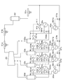
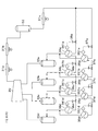
- a configuration example of the refrigeration apparatus including the ejectors 41a to 41d will be described with reference to FIGS.
- FIGS. 2 and 4 described below the same reference numerals as those used in FIG. 5 are attached to the same components as those described using FIG.
- the refrigeration apparatus shown in FIG. 2 includes a precooling refrigerant gas (refrigerant gas) extraction side from each of the precooling heat exchangers 34a to 34d provided on the precooling heat exchanger 103 side and the knockout drums 33a to 33d. Further, the point that the ejectors 41a to 41d are provided is different from the conventional refrigeration apparatus shown in FIG. On the other hand, in the auxiliary heat exchangers 35a to 35d on the auxiliary heat exchanger 105 side, the refrigeration apparatus uses the expansion valves 37a to 37d to lower the temperature of the precooling refrigerant in the auxiliary heat exchangers 35a to 35d. It is the composition which makes it.
- refrigerant gas refrigerant gas
- FIG. 3 shows a configuration example of each of the ejectors 41a to 41d (in FIG. 3, each ejector 41a to 41d is generally labeled with “41”).
- a nozzle 412 for supplying a precooling refrigerant liquid (high-pressure refrigerant liquid) to a tubular main body 416 whose rear end portion is sealed is coaxially inserted from the rear end portion side.
- a suction port 413 for sucking a precooling refrigerant gas into the main body 416 is provided on a side surface of the main body 416, and the suction port 413 is connected to a pipe for extracting gas from the precooling heat exchangers 34a to 34d.
- the distal end side of the main body 416 is reduced in diameter in the liquid discharge direction from the nozzle 412, and the downstream side of the discharge port of the nozzle 412 is a mixing unit 414 made of a pipe having a smaller diameter than the main body 416. It has become.
- a diffuser portion 415 whose diameter is gradually enlarged is provided on the outlet side of the mixing portion 414, and the ejector 41 is provided with a gas-liquid separator (corresponding to the knockout drum shown in FIG. 5) 33a via the diffuser portion 415.
- the ejector 41 having the above-described configuration, when the precooling refrigerant (liquid) accelerated at high speed in the nozzle 412 is discharged from the nozzle 412, the fluid in the main body 416 is drawn toward the precooling refrigerant flowing at high speed.
- the precooling refrigerant (gas) is sucked from the suction port 413.
- most of the precooling refrigerant extracted from the precooling heat exchangers 34a to 34d is gas, but is accompanied by a mist-like liquid of about 1.0 wt% at most.
- the ejector 41 sucks the precooling refrigerant gas and the liquid accompanying it from the precooling heat exchangers 34a to 34d.
- the precooling refrigerant gas and the liquid accompanying it may be collectively referred to as “gas”.
- the temperature of the precooling refrigerant discharged from the nozzle 412 decreases due to adiabatic expansion.
- the precooling refrigerant (liquid) discharged from the nozzle 412 and the precooling refrigerant (gas) sucked from the suction port 413 flow through the mixing unit 414 as a gas-liquid mixed fluid while being mixed with each other, and enter the diffuser unit 415. Decelerate and the pressure recovers.
- the configuration of the ejector 41 provided in the refrigeration apparatus is not limited to the example shown in FIG. 3, and the precooling refrigerant (gas) is sucked using the precooling refrigerant (liquid), and the mixed fluid thereof. As long as the voltage is increased, the configuration of each part may be changed as appropriate.
- the precooling refrigerant (liquid) supercooled by the AFC 31c is supplied to the nozzle 412 provided in the ejector 41a, while being on the outlet side (precooling refrigerant gas side) of the first stage precooling heat exchanger 34a.
- the pipe is connected to the suction port 413 of the ejector 41a.
- the exit side of the diffuser part 415 of the ejector 41a from which the gas-liquid mixed fluid of the precooling refrigerant flows out is connected to the gas-liquid separator 33a.
- the liquid flowing into the knockout drum 33a provided in the conventional refrigeration apparatus shown in FIG. 5 is a small amount of mist accompanying the precooling refrigerant gas extracted from the precooling heat exchanger 34a. Only.
- the gas-liquid separator 33a shown in FIG. 2 the mixed fluid of the precooling refrigerant gas and the liquid mixed in the ejector 41a flows, and the gas and the liquid are separated by the flow velocity decrease after the inflow. Gas-liquid separation.
- the knockout drum 33a described with reference to FIG. 5 corresponds to a gas-liquid separator that separates gas and liquid into gas and liquid in the refrigeration apparatus shown in FIG. (Same in FIG. 4).
- the precooling refrigerant gas after the gas-liquid separation is returned to the high-pressure side suction port of the compressor 20.
- a liquid pool of a liquid for precooling whose temperature is lowered by the ejector 41a is formed on the lower side of the gas-liquid separator 33a.
- the precooling refrigerant (liquid) is extracted from the liquid pool toward the precooling heat exchanger 34a through a flow path provided between the bottom of the gas-liquid separator 33a and the precooling heat exchanger 34a.
- the gas-liquid separators 33a to 33c in the previous stage with respect to the ejectors 41b to 41d (nozzles 412) provided on the outlet side of the precooling heat exchangers 34b to 34d are used.
- the structure is the same as that of the first stage except that the separated precooling refrigerant liquid is supplied. That is, gas-liquid separators 33b to 33d are provided on the outlet sides of the ejectors 41b to 41d in each stage, and the precooling refrigerant gas after the gas-liquid separation is supplied to the suction port of the compressor 20 corresponding to each pressure. Returned.
- the precooling refrigerant (liquid) is supplied from the liquid reservoirs of the gas-liquid separators 33b to 33d through the flow path provided between the bottoms of the gas-liquid separators 33b to 33d and the precooling heat exchangers 34b to 34d. Extracted and used for cooling NG.
- the gas (including the accompanying liquid) generated on the shell side of the precooling heat exchangers 34b to 34d is sucked by the ejectors 41b to 41d.
- NG is cooled to a temperature lower than that of the heat exchanger shown in the refrigeration apparatus of FIG. The same applies to the point where the gas extracted from the auxiliary heat exchangers 35b to 35d on the auxiliary heat exchanging unit 105 side joins the flow paths on the outlet side of the ejectors 41b to 41d.
- the refrigeration apparatus of the present example includes liquid levels of the precooling heat exchangers 34a to 34d.
- the expansion valves 36a to 36d for adjusting the level are not provided. Therefore, as shown in FIG. 2, liquid level gauges 341a to 341d provided in the precooling heat exchangers 34a to 34d are provided in the flow path between the gas-liquid separators 33a to 33d and the precooling heat exchangers 34a to 34d.
- Liquid level control valves 342a to 342d are provided for adjusting the flow rate of the precooling refrigerant (liquid) supplied from the gas-liquid separators 33a to 33d based on the detection result of the liquid level.
- the liquid level control valves 342a to 342d when the liquid level in each of the precooling heat exchangers 34a to 34d is lower than the target value, the liquid level control valves 342a to 342d While increasing the opening degree and increasing the supply amount of the precooling refrigerant, when the liquid level is higher than the target value, the opening amounts of the liquid level control valves 342a to 342d are reduced and the supply amount of the precooling refrigerant is increased. Control to reduce is performed.
- the above-described liquid level control valves 342a to 342d are opened and closed according to the liquid level of the precooling refrigerant in the precooling heat exchangers 34a to 34d, and the liquid reservoirs in the gas-liquid separators 33a to 34d
- the amount of precooling refrigerant withdrawn is changed independently of the amount of.
- the pre-cooling refrigerant (liquid) drawn out from the gas-liquid separators 33a to 33d is lost or the height of the liquid pool becomes too high.
- the precooling refrigerant (liquid) may flow out to the compressor 20 side.
- the gas-liquid separators 33a to 33d of this example are provided with liquid level gauges 331a to 331d for detecting the liquid level of the liquid pool.
- a flow rate for adjusting the flow rate of the liquid precooling refrigerant (high-pressure refrigerant liquid) is provided at the base end portion of the nozzle 412 provided in each of the ejectors 41a to 41d (41).
- An adjustment valve (flow rate adjustment unit) 411 is provided.
- the flow rate adjustment valve 411 is preferably provided integrally with the nozzle 412 as a part of the equipment constituting the ejector 41.
- the flow rate adjusting valve 411 may be independently provided on the upstream side of the precooling refrigerant (liquid) supply pipe connected to the nozzle 412 that does not include the flow rate adjusting valve 411.
- the flow rate adjustment valve 411 of these ejectors 41a to 41d As an example of the control executed by the flow rate adjustment valves 411 of these ejectors 41a to 41d, when the liquid level in each of the gas-liquid separators 33a to 33d is lower than the target value, the flow rate adjustment valve 411 is opened. When the liquid level is higher than the target value while increasing the degree of supply of the precooling refrigerant, control is performed to reduce the supply amount of the precooling refrigerant by reducing the opening of the flow rate adjustment valve 411. Done.
- the operation of the refrigeration apparatus described above will be described.
- the supplied amount of the precooling refrigerant (liquid) supercooled by the AFC 31c is increased or decreased on the precooling heat exchange unit 103 side in accordance with the liquid level of the gas-liquid separator 33a.
- the suction amount of the precooling refrigerant gas (including the accompanying liquid) sucked from the precooling heat exchanger 34a side is increased or decreased in accordance with the supply amount of the precooling refrigerant (liquid).
- the gas-liquid mixed fluid of the pre-cooling refrigerant discharged from the ejector 41a is separated in the gas-liquid separator 33a, and the gas is returned to the suction port of the compressor 20, while the liquid is the gas-liquid separator.
- a liquid pool is formed in 33a.
- a part of the precooling refrigerant constituting the liquid pool is extracted toward the precooling heat exchanger 34a in accordance with the liquid level in the precooling heat exchanger 34a, and is used for cooling NG.
- a part of the precooling refrigerant in the liquid pool is extracted toward the second-stage ejector 41b, and the extraction amount is at the liquid level of the precooling refrigerant in the second-stage gas-liquid separator 33b. Increase or decrease accordingly.
- the liquid level of the precooling heat exchangers 34a to 34d varies depending on the flow rate of NG to be cooled, the inlet temperature of the NG in each of the precooling heat exchangers 34a to 34d, and the like.
- the liquid level in the second-stage gas-liquid separator 33b also changes according to the liquid-level level in the second-stage precooling heat exchanger 34b and the third-stage gas-liquid separator 33c.
- the total amount of precooling refrigerant (liquid) used in the precooling heat exchanger 34a and the ejector 41b connected to the gas-liquid separator 33a is collectively detected as the liquid level in the gas-liquid separator 33a.
- the supply amount of the pre-cooling refrigerant (liquid) to the ejector 41a is increased or decreased so that the liquid level becomes constant.
- the precooling heat exchanger 34a and the ejector 41b can freely use the precooling refrigerant in accordance with the load within the range of the compressor 20 and the AFC 31a to 31c.
- the refrigeration apparatus can be operated without causing restrictions on the amount of refrigerant used.
- the loads of the precooling heat exchangers 34b to 34d provided in each stage and the ejectors 41c to 41d in the subsequent stages are increased or decreased according to the load of only the precooling heat exchanger 34d).
- the pre-cooling heat exchangers 34b to 34d and the ejectors 41c and 41d in the second and subsequent stages can freely use the pre-cooling refrigerant according to the load and do not cause individual usage amount restrictions.
- a part of the precooling refrigerant (liquid) thus supercooled by the AFC 31c is cooled by the ejectors 41a to 41d, and then each precooling heat exchanger 34a to 34a is passed through the gas-liquid separators 33a to 33d downstream thereof. 34d, where it is used to cool NG. Then, the precooling refrigerant gas generated in the precooling heat exchangers 34a to 34d is sucked into the ejectors 41a to 41d together with the accompanying liquid, and is passed through the gas-liquid separators 33a to 33d, and the related art shown in FIG. NG can be cooled to a temperature lower than that of the precooling heat exchangers 34a to 34d of the refrigeration apparatus.
- the remaining part of the precooling refrigerant (liquid) supercooled by the AFC 31c is the expansion valves 37a to 37d on the auxiliary heat exchange unit 105 side, as in the conventional refrigeration apparatus described with reference to FIG.
- the pre-cooling refrigerant whose temperature has gradually decreased is used for cooling the main refrigerant, and the liquid level of the auxiliary heat exchangers 35a to 35d is adjusted by adjusting the opening degree of each expansion valve 37a to 37d.
- the precooling refrigerant gas extracted from each of the auxiliary heat exchangers 35a to 35d joins the precooling refrigerant gas on the precooling heat exchange section 103 side together with the accompanying liquid, and passes through the gas-liquid separators 33a to 33d. To the suction port of the compressor 20.
- the refrigeration apparatus has the following effects.
- a liquid precooling refrigerant (high-pressure refrigerant liquid) obtained after being compressed by the compressor 20 is adiabatically expanded by the ejectors 41a to 41d, and NG (covered by the precooling heat exchangers 34a to 34d).
- the precooling refrigerant (refrigerant gas) used for cooling the cooling liquid) is sucked and sent to the gas-liquid separators 33a to 33d, and the refrigerant gas separated from the gas-liquid is returned to the compressor 20, while the liquid precooling is performed.
- the flow rate of the precooling refrigerant supplied to the precooling heat exchangers 34a to 34d is adjusted based on the liquid level of the precooling refrigerant in each of the precooling heat exchangers 34a to 34d, while the ejectors 41a to 41d.
- the flow rate of the precooling refrigerant (liquid) supplied to is adjusted based on the liquid level of the gas-liquid separators 33a to 33d.
- the pre-cooling refrigerant supplied to the pre-cooling heat exchangers 34a to 34d is supplied to the pre-cooling heat exchangers 34a to 34d while supplying the pre-cooling refrigerant necessary for cooling the NG to the pre-cooling heat exchangers 34a to 34d. It is possible to prevent the refrigerant from running out and the precooling refrigerant from flowing out to the compressor 20.
- the installation locations of the ejectors are 41a to 41d. Any one of them, for example, 41a alone, or two or more ejectors, for example, 41a and 42b, may be provided in any combination. Furthermore, the system in which the ejector 41 is provided may be on the auxiliary heat exchange unit 105 side.
- strain which provides the ejector 41 is not limited to any one of the pre-cooling heat exchange part 103 and the liquefaction part 104, You may provide in both systems.
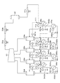
- FIG. 4 shows an example of a refrigeration apparatus in which common ejectors 41 a to 41 d are provided in both systems of the pre-cooling heat exchange unit 103 and the auxiliary heat exchange unit 105.
- the flow path for extracting the precooling refrigerant (liquid) from the liquid pools of the gas-liquid separators 33a to 33d to the precooling heat exchangers 34a to 34d on the precooling heat exchanging unit 103 side is branched in the middle to assist
- the auxiliary heat exchangers 35a to 35d on the heat exchange unit 105 side are connected.
- the outlet side pipes of the auxiliary heat exchangers 35a to 35d (gas side of the precooling refrigerant) merge with the outlet side pipes of the precooling heat exchangers 34a to 34d side of the precooling heat exchanging unit 103 side,
- the suction ports 413 of the ejectors 41a to 41d are connected.
- each of the ejectors 41a to 41d includes two sets of precooling heat exchangers 34a to 34d and 35a to 35d provided in both systems of the precooling heat exchanging unit 103 and the auxiliary heat exchanging unit 105 from the upper side.
- the gas (including the accompanying liquid) generated in the precooling heat exchangers 34a to 34d and 35a to 35d of each set can be sucked.
- liquid level gauges 351a to 351d for detecting the internal liquid level, and detection of the liquid level by these liquid level gauges 351a to 351d Based on the results, liquid level control valves 352a to 352d for adjusting the flow rate of the precooling refrigerant (liquid) supplied from the gas-liquid separators 33a to 33d to the auxiliary heat exchangers 35a to 35d are provided.
- each of the ejectors 41a to 41d adjusts the flow rate of the liquid precooling refrigerant based on the liquid level of the gas-liquid separators 33a to 33d, which is the same as the refrigeration apparatus described with reference to FIG. It is.
- precooling heat exchangers 34a to 34d on the precooling heat exchanging section 103 side correspond to first heat exchangers, from gas-liquid separators 33a to 33d to precooling heat exchangers 34a to 34d.
- the flow path of the precooling refrigerant corresponds to the first branch flow path.
- NG cooled by the precooling heat exchangers 34a to 34d corresponds to the first fluid to be cooled, and the liquid level control valves 342a to 342d provided in the respective precooling heat exchangers 34a to 34d are the first liquid level. It corresponds to a control valve.
- the auxiliary heat exchangers 35a to 35d on the auxiliary heat exchanging unit 105 side correspond to a second heat exchanger, and the flow path of the precooling refrigerant from the gas-liquid separators 33a to 33d to the auxiliary heat exchangers 35a to 35d.
- the main refrigerant cooled by the auxiliary heat exchangers 35a to 35d corresponds to the second fluid to be cooled, and the liquid level control valves 352a to 352d provided in the auxiliary heat exchangers 35a to 35d are the second liquid. It corresponds to a surface control valve.
- the pressure of the heat exchangers (pre-cooling heat exchangers 34a to 34d, auxiliary heat exchangers 35a to 35d) is lower than that of the gas-liquid separators 33a to 33d, that is, at a lower temperature. Since it can be operated, the fluid to be cooled can be cooled to a lower temperature. Alternatively, it is possible to reduce the load on the compressor 20 by increasing the suction pressure of the compressor 20 by setting the temperature level of these heat exchangers to be the same as the conventional one, and select either one freely. Can drive.
- the ejectors 41a to 41d are provided in the precooling heat exchangers 34a to 34d of the precooling heat exchanging unit 103 and the auxiliary heat exchangers 35a to 35d of the auxiliary heat exchanging unit 105. It is not essential to provide 41a to 41d. For example, the effects obtained by replacing the conventional expansion valves 36a to 36d and 37a to 37d with the ejectors 41a to 41d may be compared with the cost, and the ejectors 41a to 41d may be provided at positions where the merit is greatest.
- the case where only the most upstream stage expansion valve 36a and / or 37a is replaced with the ejector 41a may be used.
- the upstream side expansion valve has a larger pressure difference before and after adiabatic expansion, and the effect of replacing it with the ejectors 41a to 41d is increased, while the size of the ejectors 41a to 41d is upstream. There is a tendency to become larger toward the step side.
Landscapes
- Engineering & Computer Science (AREA)
- Physics & Mathematics (AREA)
- Mechanical Engineering (AREA)
- Thermal Sciences (AREA)
- General Engineering & Computer Science (AREA)
- Chemical & Material Sciences (AREA)
- Chemical Kinetics & Catalysis (AREA)
- General Chemical & Material Sciences (AREA)
- Oil, Petroleum & Natural Gas (AREA)
- Separation By Low-Temperature Treatments (AREA)
Abstract
L'invention fournit un dispositif frigorifique qui est équipé d'un cycle frigorifique incluant un éjecteur. L'éjecteur (41a) condense un gaz réfrigérant haute pression déchargé par un compresseur (20), aspire le gaz réfrigérant par injection d'un liquide réfrigérant haute pression ainsi obtenu, et élève la pression de ces fluides mélangés. Un séparateur gaz/liquide (33a) effectue une séparation gaz/liquide vis-à-vis desdits fluides mélangés, et envoie au compresseur (20) le gaz réfrigérant ainsi séparé. Un échangeur de chaleur (34a) effectue un échange de chaleur entre un liquide réfrigérant et un fluide à refroidir séparés au niveau du séparateur gaz/liquide (33a), et le gaz réfrigérant ainsi produit est aspiré par un orifice d'aspiration dudit éjecteur (41a). Une valve de réglage de niveau (342a) ajuste le débit du liquide réfrigérant sur la base du niveau de liquide réfrigérant dans l'échangeur de chaleur (34a). Une partie régulation de débit (411) régule le débit liquide réfrigérant haute pression alimentant l'éjecteur (41a) sur la base du niveau de liquide à l'intérieur du séparateur gaz/liquide (33a).
Priority Applications (1)
| Application Number | Priority Date | Filing Date | Title |
|---|---|---|---|
| PCT/JP2014/006469 WO2016103295A1 (fr) | 2014-12-25 | 2014-12-25 | Dispositif frigorifique |
Applications Claiming Priority (1)
| Application Number | Priority Date | Filing Date | Title |
|---|---|---|---|
| PCT/JP2014/006469 WO2016103295A1 (fr) | 2014-12-25 | 2014-12-25 | Dispositif frigorifique |
Publications (1)
| Publication Number | Publication Date |
|---|---|
| WO2016103295A1 true WO2016103295A1 (fr) | 2016-06-30 |
Family
ID=56149399
Family Applications (1)
| Application Number | Title | Priority Date | Filing Date |
|---|---|---|---|
| PCT/JP2014/006469 Ceased WO2016103295A1 (fr) | 2014-12-25 | 2014-12-25 | Dispositif frigorifique |
Country Status (1)
| Country | Link |
|---|---|
| WO (1) | WO2016103295A1 (fr) |
Cited By (3)
| Publication number | Priority date | Publication date | Assignee | Title |
|---|---|---|---|---|
| CN107990630A (zh) * | 2017-11-17 | 2018-05-04 | 国鸿液化气机械工程(大连)有限公司 | 天然气液化系统、降低压缩机功率消耗的方法及于再液化中的应用 |
| WO2021030112A1 (fr) * | 2019-08-13 | 2021-02-18 | Bechtel Oil, Gas And Chemicals, Inc. | Systèmes et procédés pour améliorer l'efficacité des systèmes de gaz naturel liquéfié en cascade à cycle ouvert |
| CN119825681A (zh) * | 2025-01-20 | 2025-04-15 | 西安交通大学 | 一种离子液氢气压缩机离子液循环和无动力喷射补液装置 |
Citations (9)
| Publication number | Priority date | Publication date | Assignee | Title |
|---|---|---|---|---|
| JPS5128101A (en) * | 1974-08-09 | 1976-03-09 | Linde Ag | Tennengasuno ekikahoho |
| JPH0611199A (ja) * | 1991-11-20 | 1994-01-21 | Nippon Sanso Kk | 超臨界ヘリウム発生装置 |
| JPH06265230A (ja) * | 1993-03-11 | 1994-09-20 | Kobe Steel Ltd | 液化冷凍装置の運転制御方法及び装置 |
| JPH06272977A (ja) * | 1993-03-23 | 1994-09-27 | Daikin Ind Ltd | 満液式蒸発器 |
| JP2002349978A (ja) * | 2000-08-04 | 2002-12-04 | Denso Corp | エジェクタサイクル |
| JP2006118726A (ja) * | 2004-10-19 | 2006-05-11 | Denso Corp | エジェクタサイクル |
| JP2006228118A (ja) * | 2005-02-21 | 2006-08-31 | Fuji Electric Retail Systems Co Ltd | 自動販売機 |
| JP2010243095A (ja) * | 2009-04-08 | 2010-10-28 | Mitsubishi Electric Corp | 冷凍サイクル装置及び気液分離器 |
| US20130111944A1 (en) * | 2010-07-23 | 2013-05-09 | Carrier Corporation | High Efficiency Ejector Cycle |
-
2014
- 2014-12-25 WO PCT/JP2014/006469 patent/WO2016103295A1/fr not_active Ceased
Patent Citations (9)
| Publication number | Priority date | Publication date | Assignee | Title |
|---|---|---|---|---|
| JPS5128101A (en) * | 1974-08-09 | 1976-03-09 | Linde Ag | Tennengasuno ekikahoho |
| JPH0611199A (ja) * | 1991-11-20 | 1994-01-21 | Nippon Sanso Kk | 超臨界ヘリウム発生装置 |
| JPH06265230A (ja) * | 1993-03-11 | 1994-09-20 | Kobe Steel Ltd | 液化冷凍装置の運転制御方法及び装置 |
| JPH06272977A (ja) * | 1993-03-23 | 1994-09-27 | Daikin Ind Ltd | 満液式蒸発器 |
| JP2002349978A (ja) * | 2000-08-04 | 2002-12-04 | Denso Corp | エジェクタサイクル |
| JP2006118726A (ja) * | 2004-10-19 | 2006-05-11 | Denso Corp | エジェクタサイクル |
| JP2006228118A (ja) * | 2005-02-21 | 2006-08-31 | Fuji Electric Retail Systems Co Ltd | 自動販売機 |
| JP2010243095A (ja) * | 2009-04-08 | 2010-10-28 | Mitsubishi Electric Corp | 冷凍サイクル装置及び気液分離器 |
| US20130111944A1 (en) * | 2010-07-23 | 2013-05-09 | Carrier Corporation | High Efficiency Ejector Cycle |
Cited By (3)
| Publication number | Priority date | Publication date | Assignee | Title |
|---|---|---|---|---|
| CN107990630A (zh) * | 2017-11-17 | 2018-05-04 | 国鸿液化气机械工程(大连)有限公司 | 天然气液化系统、降低压缩机功率消耗的方法及于再液化中的应用 |
| WO2021030112A1 (fr) * | 2019-08-13 | 2021-02-18 | Bechtel Oil, Gas And Chemicals, Inc. | Systèmes et procédés pour améliorer l'efficacité des systèmes de gaz naturel liquéfié en cascade à cycle ouvert |
| CN119825681A (zh) * | 2025-01-20 | 2025-04-15 | 西安交通大学 | 一种离子液氢气压缩机离子液循环和无动力喷射补液装置 |
Similar Documents
| Publication | Publication Date | Title |
|---|---|---|
| CN105473967B (zh) | 混合制冷剂系统和方法 | |
| JP7253579B2 (ja) | 混合冷媒システムおよび方法 | |
| JP6117298B2 (ja) | 予備冷却される混合冷媒統合システムおよび方法 | |
| CN106461320B (zh) | 使用优化的混合制冷剂系统的液化天然气设施 | |
| JP6286812B2 (ja) | 天然ガス液化装置の混合冷媒組成の決定方法 | |
| CN113865266B (zh) | 液化系统 | |
| JP2008530505A (ja) | 天然ガスを液化するためのプラント及び方法 | |
| US10180282B2 (en) | Parallel compression in LNG plants using a positive displacement compressor | |
| EP3299757B1 (fr) | Procédé et système de refroidissement de réfrigérant mixte | |
| CN205957595U (zh) | 一种用于单混合制冷剂过程的设备 | |
| CN105102913A (zh) | 天然气液化方法和装置 | |
| US7628035B2 (en) | Method for processing a stream of LNG obtained by means of cooling using a first refrigeration cycle and associated installation | |
| US20230194161A1 (en) | Standalone high-pressure heavies removal unit for lng processing | |
| CN107917577A (zh) | 多压力混合的制冷剂冷却方法和系统 | |
| RU2614947C1 (ru) | Способ переработки природного газа с извлечением С2+ и установка для его осуществления | |
| AU2015388393B2 (en) | Natural gas production system and method | |
| WO2016103295A1 (fr) | Dispositif frigorifique | |
| WO2016103296A1 (fr) | Dispositif frigorifique | |
| RU2621572C2 (ru) | Способ обратного сжижения богатой метаном фракции | |
| CA3007571C (fr) | Procede de liquefaction de gaz naturel et d'azote | |
| CN109724279A (zh) | 单级节流单循环混合冷剂制冷系统及方法 |
Legal Events
| Date | Code | Title | Description |
|---|---|---|---|
| 121 | Ep: the epo has been informed by wipo that ep was designated in this application |
Ref document number: 14908906 Country of ref document: EP Kind code of ref document: A1 |
|
| NENP | Non-entry into the national phase |
Ref country code: DE |
|
| 122 | Ep: pct application non-entry in european phase |
Ref document number: 14908906 Country of ref document: EP Kind code of ref document: A1 |
|
| NENP | Non-entry into the national phase |
Ref country code: JP |