WO2016103444A1 - Procédé de fabrication d'une ailette d'échangeur de chaleur - Google Patents
Procédé de fabrication d'une ailette d'échangeur de chaleur Download PDFInfo
- Publication number
- WO2016103444A1 WO2016103444A1 PCT/JP2014/084500 JP2014084500W WO2016103444A1 WO 2016103444 A1 WO2016103444 A1 WO 2016103444A1 JP 2014084500 W JP2014084500 W JP 2014084500W WO 2016103444 A1 WO2016103444 A1 WO 2016103444A1
- Authority
- WO
- WIPO (PCT)
- Prior art keywords
- product width
- metal strip
- row
- inter
- heat exchanger
- Prior art date
- Legal status (The legal status is an assumption and is not a legal conclusion. Google has not performed a legal analysis and makes no representation as to the accuracy of the status listed.)
- Ceased
Links
Images


Classifications
-
- B—PERFORMING OPERATIONS; TRANSPORTING
- B21—MECHANICAL METAL-WORKING WITHOUT ESSENTIALLY REMOVING MATERIAL; PUNCHING METAL
- B21D—WORKING OR PROCESSING OF SHEET METAL OR METAL TUBES, RODS OR PROFILES WITHOUT ESSENTIALLY REMOVING MATERIAL; PUNCHING METAL
- B21D53/00—Making other particular articles
- B21D53/02—Making other particular articles heat exchangers or parts thereof, e.g. radiators, condensers fins, headers
- B21D53/08—Making other particular articles heat exchangers or parts thereof, e.g. radiators, condensers fins, headers of both metal tubes and sheet metal
Definitions
- the present invention relates to a heat exchanger fin manufacturing method for manufacturing a heat exchanger fin having a plurality of through holes or a plurality of notches.
- heat exchangers such as coolers are generally configured by laminating a plurality of heat exchanger fins each having a plurality of through holes into which heat exchange tubes are inserted.
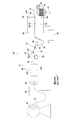
- Such heat exchanger fins can be manufactured by a heat exchanger fin manufacturing apparatus 1 as shown in FIG. 7 (see Patent Document 1).
- the heat exchanger fin manufacturing apparatus 1 is provided with an uncoiler 12 in which a thin metal plate 10 such as aluminum is wound in a coil shape.
- the thin plate 10 drawn from the uncoiler 12 through the pinch roll 14 is inserted into the oil applying device 16, and after processing oil is attached to the surface of the thin plate 10, the thin plate 10 is applied to the mold device 20 provided in the press device 18. Supplied.
- the mold apparatus 20 is provided with an upper die set 22 that can move up and down and a lower die set 24 that is stationary.
- a plurality of collared through holes (not shown) in which a collar having a predetermined height is formed around the through holes are formed at predetermined intervals (matrix-like arrangement) in a predetermined direction.
- a metal thin plate in which through holes and the like are processed is referred to as a metal strip 11.
- the processed metal strip 11 is formed in a state in which a plurality of heat exchanger fins that are products are arranged in the width direction. For this reason, an inter-row slit device 25 is provided at a downstream position of the mold device 20.
- the inter-row slit device 25 cuts the metal strip 11 intermittently fed by the first feeding device 26 with the upper blade 25A and the lower blade 25B engaged with each other, and has a long strip-like product width metal strip. 11A is formed.
- the metal strip 11A having a product width is cut into a predetermined length by the cutter 27 and formed on the heat exchanger fin 13 which is a manufacturing object.
- the heat exchanger fins 13 are accommodated in the stacker 28.
- a plurality of pins 29 are erected on the stacker 28 in the vertical direction.
- the heat exchanger fins 13 are stacked and held on the stacker 28 by inserting pins 29 into the through holes formed in the heat exchanger fins 13.
- the conventional heat exchanger fin 13 has a plurality of through holes into which the heat exchange tube is inserted into the metal strip 11.
- heat exchangers using multi-hole flat tubes are in circulation.
- the fins for heat exchangers using this flat tube are shown in FIGS. 8A and 8B.
- a plurality of tube insertion portions 34 into which the flat tubes 32 are inserted are formed at a predetermined interval, and a louver 35 is formed between the tube insertion portion 34 and the tube insertion portion 34.
- a plate-like portion 36 is formed.
- the tube insertion portion 34 is formed only from one side in the width direction of the heat exchanger fin 30. Accordingly, the plurality of plate-like portions 36 between the tube insertion portion 34 and the tube insertion portion 34 are connected by a connection portion 38 extending along the longitudinal direction.
- the cut and raised portion 37 is for forming a gap between the upper and lower heat exchanger fins 30 when the heat exchanger fins 30 are stacked.
- the length of the product is arbitrarily changed.
- the feed length of one cut-off can be made longer than the feed length of one time (one mold closing) of the metal strip having the product width in the inter-row slit device.
- the metal strip having the product width is slacked downward.
- Patent Document 2 discloses a configuration of a heat exchanger fin manufacturing apparatus having a control unit for managing a slack state of a product width metal strip downward.
- the configuration of the control unit disclosed in Patent Document 2 may have complicated control contents, and the heat exchanger fin manufacturing apparatus employing such a control unit has a problem that the provision cost is expensive. is there.
- the heat exchanger fin manufacturing apparatus In order to prevent the entanglement of the metal strip of the product width without adopting such an expensive control unit, when trying to separate the metal strips of the product width, the heat exchanger fin manufacturing apparatus itself, or Increase in installation area becomes inevitable. Thereby, the manufacturing amount of the fin for heat exchanger per unit area of a factory will fall, and also the subject that reduction of the manufacturing cost of the fin for heat exchanger will be inhibited.
- the present invention has been made to solve all the above problems, and the object of the present invention is to prevent metal strips of product width from being entangled even with a conventional heat exchanger fin manufacturing apparatus.
- An object of the present invention is to provide a heat exchanger fin manufacturing method that can be used.
- the present invention includes a step of forming a metal strip having a plurality of through holes or a plurality of notches, and a plurality of the strips in the row direction by cutting the metal strip in a row direction by an inter-row slit device.
- the length of the metal strip having the product width between the slit device between rows and the cutoff device is different between adjacent metal strips having the product width.
- the metal strip of the product width is lowered between the inter-row slit device and the cut-off device without arranging a new configuration between the inter-row slit device and the cut-off device. It is possible to prevent the metal strips having the product width from being entangled in the slack portion. Thereby, the manufacturing yield of the heat exchanger fins can be improved without adding a new configuration to the heat exchanger fin manufacturing apparatus.
- the slit device between the rows.
- the tip portion in the feeding direction of the metal strip having the product width sent out from is attached to the second feeding device, it is attached to the second feeding device between the adjacent metal strips having the product width. It is preferable that the position is shifted in the feed direction.
- the front end portion in the feeding direction of the metal strip having the product width is attached to the second feeding device in a state of being shifted between the adjacent metal strips having the product width, and then attached to the second feeding device. It is preferable to cut off an excessive length portion of the metal strip having the product width.
- the tip portion in the feeding direction of the metal strip having the product width fed from the inter-row slit device is mounted on the second feeding device, the slits between the rows of the metal strip having the product width adjacent to each other. It is preferable that the length dimension in the feeding direction between the apparatus and the cut-off apparatus is made different in advance.
- a metal strip having a product width in a state of being slacked downward between the inter-row slit apparatus and the cutoff apparatus It is possible to maintain a state where they are separated so as not to be entangled with each other. Therefore, the manufacturing yield can be improved without costing the manufacturing apparatus, and the manufacturing cost of the product can be reduced.
- FIG. 2 is an end view taken along line AA in FIG. 1. It is a side view which shows the modification of a receiving part. It is explanatory drawing which shows the example of a conventional structure of the manufacturing apparatus which manufactures the fin for heat exchangers.
- FIG. 8A is a plan view of the heat exchanger fin.
- FIG. 8B is a side view of the heat exchanger fin.
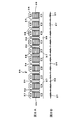
- FIG. 1 shows the overall configuration of a heat exchanger fin manufacturing apparatus according to the present embodiment.
- An unprocessed metal thin plate 41 such as aluminum is wound around an uncoiler 40 in a coil shape.
- the thin plate 41 pulled out from the uncoiler 40 is inserted into the loop controller 42, and fluttering of the thin plate 41 that is intermittently fed is suppressed by the loop controller 42.
- An NC feeder 44 is provided on the downstream side of the loop controller 42.
- the NC feeder 44 is composed of two rollers that are in contact with the upper surface and the lower surface of the thin plate 41. When the two rollers are driven to rotate, the thin plate 41 is sandwiched between each other to intermittently feed the thin plate 41.
- a press device 47 in which a mold device 46 is disposed is provided on the downstream side of the NC feeder 44.
- the mold apparatus 46 of the present embodiment has an upper die set 46A and a lower die set 46B, and one of the upper die set 46A and the lower die set 46B is provided so as to be movable toward and away from the other. It has been.
- the thin plate 41 is formed into a metal strip 48 having a predetermined shape by the mold device 46.
- the metal strip 48 formed here is shown in FIG.
- the metal strip 48 shown in FIG. 2 is formed by arranging four rows of product groups in the width direction (vertical arrow in FIG. 2) orthogonal to the transport direction (horizontal arrow in FIG. 2). .
- Each product obtained by dividing the metal band 48 into individual pieces will be described with reference to FIGS. 8A and 8B, and the tube insertion portions 34 into which the flat tubes 32 are inserted are formed at a plurality of locations. Between the tube insertion part 34 and the tube insertion part 34, the plate-shaped part 36 in which the louver 35 was formed is formed.
- cut and raised portions 37 formed by cutting and raising a part of the plate-like portion 36 are formed.
- the two raised portions 37, 37 with respect to one louver 35 the one raised portion 37 is formed on the distal end side of the plate-like portion 36.
- the tube insertion portion 34 is formed only from one side in the width direction of the heat exchanger fin 30. Accordingly, the plurality of plate-like portions 36 between the tube insertion portion 34 and the tube insertion portion 34 are connected by a connection portion 38 extending along the longitudinal direction. Of the two raised portions 37, 37 for the one louver 35, the other raised portion 37 is formed on the connecting portion 38.
- the metal strip 48 shown in FIG. 2 is formed of two sets in which two products are arranged so that the opening sides of the tube insertion portions 34 face each other. That is, a set in which the opening sides of the tube insertion portions 34 of the two products are opposed to each other is arranged so that the connecting portions 38 are adjacent to each other.
- the four products are arranged so as to face each other, the left and right load balance between the mold device 46 and the metal strip 48 is improved.
- the inter-row slit device 52 (described later) that separates each product group. )
- the tube insertion portion 34 is not located at the boundary of the opening portion of the tube insertion portion 34 but to the position where it enters the connecting portion 38 portion. It becomes necessary to slightly widen and cut the opening.
- a step is generated in the cross section, and the left and right load balance of the mold is deteriorated. Therefore, it is preferable to manufacture a plurality of products in the arrangement as shown in FIG.
- the metal strip 48 formed by the mold device 46 in the press device 47 is intermittently fed in the transport direction by the first feeding device 50 provided on the downstream side of the press device 47.
- the feed timing of the first feeding device 50 is provided so as to operate in conjunction with the NC feeder 44, and enables stable intermittent feeding.
- a reciprocating unit 51 that is movable in the horizontal direction reciprocates between an initial position and a transfer position to pull the metal strip 48.
- a feed pin 55 is disposed on the upper surface of the reciprocating unit 51 so as to protrude upward. The feed pin 55 enters the tube insertion portion 34 formed in the metal strip 48 from below, and the feed pin 55 is pulled. As a result, the metal strip 48 moves to the transfer position.
- An inter-row slit device 52 is provided on the downstream side of the first feeding device 50.
- the inter-row slit device 52 includes an upper blade 53 disposed on the upper surface side of the metal strip 48 and a lower blade 54 disposed on the lower surface side of the metal strip 48.
- the inter-row slit device 52 may be provided so as to operate using the vertical movement operation of the press device 47.
- the upper blade 53 and the lower blade 54 are formed long in the conveying direction of the metal strip 48, and the intermittently fed metal strip 48 is cut by the meshed upper blade 53 and lower blade 54, It is formed on a metal strip 49 having a product width, which is an intermediate product that is long in the conveying direction.
- a second feeding device 62 that intermittently conveys the metal strip 49 of each product width in the conveying direction is provided.
- the structure of the second feeding device 62 is configured such that one feeding length can be made longer than the structure of the first feeding device 50 provided on the downstream side of the pressing device 47. .
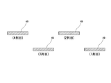
- the receiving portion 56 in the present embodiment is disposed in a state corresponding to the delivery position of the metal strip 49 having a product width divided into a plurality of pieces by the inter-row slit device 52.
- the receiving portion 56 is rubbed against the conveyance surface height position of the metal strip 49 having the product width in the inter-row slit device 52 and protrudes from the inter-row slit device 52 toward the cut-off device 60. In this way it is extended.
- the metal strip 49 having the product width sent out from the inter-row slit device 52 is supported by the lower surface so that the cut-off device is prevented from being deformed by its own weight. It will be guided towards 60.
- the receiving portion 56 in the present embodiment is formed in a curved shape that is convex upward from the inter-row slit device 52 toward the cut-off device 60 side.
- the metal strip 49 having the product width fed from the inter-slit slit device 52 does not sag suddenly downward due to its own weight, and the metal strip 49 having the product width is formed. Unintended bent portions are prevented from being formed.
- the receiving portion 56 is preferably detachable from the downstream end position in the direction (conveying direction) in which the metal strip 49 having the product width from the inter-row slit device 52 is sent out.
- an attaching / detaching form an attaching / detaching structure using a fastening means such as a screw or a magnet can be adopted.
- an extension structure adopted in a fishing rod, a tripod, etc., and a plurality of arms A structure or the like that can be rotated (bent) can be employed.
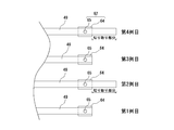
- a plurality (four in the present embodiment) of the metal strips 49 having the product width are spaced by a predetermined interval (described later). Depending on the structure of the stacking device, it is arranged so as to be open about 5-10 mm.
- the metal strips 49 having a plurality of product widths are stored in a length longer than a single feed length by the cut-off device 60. (See Fig. 1).
- the weight balance in the direction (width direction) orthogonal to the horizontal side in the transport direction is not symmetric with respect to the center line in the transport direction. For this reason, if the product-width metal strip 49 is intermittently fed in a state where the product-width metal strip 49 is slacked downward, the product-width metal strip 49 swings in the slacked portion. Then, there is a possibility that the adjacent metal strips 49 having the product width will be entangled.
- the tip of the metal strip 49 having the product width sent out from the inter-row slit device 52 is mounted on the second feeding device 62 (feeding pin 65 of the transport unit 64), the first The mounting positions in the feed direction of the metal strips 49 having the product widths in the second and fourth rows and the second and fourth rows are made different (shifted). That is, the length of the metal strip 49 having the product width in the first row and the third row between the slit device 52 and the cut-off device 60, and the product width in the second row and the fourth row. The lengths of the metal strips 49 are different.
- the process of changing the length of the metal strip 49 having the product width between the inter-row slit device 52 and the cut-off device 60 is performed at the time of setting the heat exchanger fins 30 before the start of production, This is performed when the metal thin plate 41 is replaced.
- the heat exchanger fin manufacturing apparatus 100 is operated for a short time to form a metal strip 48 (S 1), and the metal strip 49 having a product width is formed by the inter-row slit device 52. (S2), and a metal strip 49 having a product width longer than the distance between the inter-row slit device 52 and the cut-off device 60 is sent out (S3).
- the operation of the heat exchanger fin manufacturing apparatus 100 is temporarily stopped (S4).
- the operator connects the leading end of the product-width metal strip 49 sent between the inter-row slit device 52 and the cut-off device 60 between the adjacent product-width metal strips 49 and the inter-row slit device 52.
- the length between the cut-off device 60 and the cut-off device 60 is set on the feed pin 65 of the second feed device 62 (S5), and the operation of the heat exchanger fin manufacturing device 100 is resumed (S6).
- the metal strip 49 having the product width sent out from the inter-row slit device 52 sags downward between the inter-row slit device 52 and the cut-off device 60. After entering the state, it is sent to the cutoff device 60 (S7).
- the metal strip 49 having the product width fed into the cut-off device 60 is cut into a required length in the feed direction, and is formed on the heat exchanger fin 30 as the final product (S8).
- the lengths of the metal strips 49 having the product width in the first row and the third row between the inter-row slit device 52 and the cut-off device 60 are represented by the inter-row slit device 52 and the cut-off device 60. It is made longer than the length of the metal strip 49 of the product width of the 2nd row
- the second feeding device 62 is mounted in a protruding state.
- the amount of sag in the lower part of the metal strip 49 of the product width in the first row and the third row between the inter-row slit device 52 and the cut-off device 60 is the same as that between the inter-row slit device 52 and the cut-off device.
- the amount of product slack in the second row and the fourth row between the device 60 and the device 60 can be larger than the amount of sag in the downward direction of the metal strip 49.
- a loop shape (hereinafter sometimes simply referred to as a loop shape) formed by a portion where the metal strip 49 having a product width sags downward is adjacent to the product width. It becomes different between the metal strips 49, and the separation distance between the metal strips 49 of the adjacent product width can be increased. As a result, it is possible to prevent the entanglement of the metal strips 49 of adjacent product widths in the downward slack portion between the inter-row slit device 52 and the cut-off device 60.
- the lengths of the heat exchanger fins 30 can be made uniform, and the heat exchanger fins 30 from the first shot can be used as they are as the final product.
- column similarly to the metal strip
- the amount of protrusion from the inter-row slit device 52 of the receiving portion 56 corresponding to the second row and the fourth row is made different. More specifically, the metal of the product width of the second row and the fourth row is larger than the protruding amount of the receiving portion 56 corresponding to the metal strip 49 of the product width of the first row and the third row. The amount of protrusion of the receiving portion 56 corresponding to the belt-like body 49 is increased.
- the metal strips 49 having the four product widths sent out from the inter-row slit device 52 have different projection amounts of the receiving portions 56 from the inter-row slit device 52, so that the first row and the third row. In the second row and the fourth row, it is possible to further increase the amount of difference in the downward slack state after being separated from the inter-row slit device 52.
- the metal strips 49 having the product widths in the second row and the fourth row, to which the receiving portions 56 having a large amount of protrusion from the inter-row slit device 52 are attached are arranged in the transport direction of the inter-row slit device 52. After being transported in the horizontal direction over the required distance along the upper surface of the receiving portion 56 from the downstream end position, it will sag in a substantially U shape downward due to its own weight.
- the metal strips 49 having the product width in the first row and the third row with a small amount of protrusion from the inter-row slit device 52 are the metal strips having the product width in the second row and the fourth row. 49 starts to sag downward at a position closer to the inter-row slit device 52 than the sag starting position of 49 below.
- the lower apex position of the loop-shaped portion due to the metal strip 49 of the product width in the second row and the fourth row, and the lower side of the loop-shaped portion due to the metal strip 49 of the product width in the first row and the third row The height will also differ depending on the vertex position.
- the downward slack start position of the product width metal strip 49 and the height position of the lower vertex (substantially)
- the aspect ratio of the U-shaped loop shape portion can be varied.
- the metal having the product width adjacent in the horizontal direction between the inter-row slit device 52 and the cutoff device 60 due to the difference in the protruding amount of the receiving portion 56 with respect to the inter-row slit device 52, the metal having the product width adjacent in the horizontal direction between the inter-row slit device 52 and the cutoff device 60.
- the belt-like body 49 can be largely shifted in the horizontal (width) direction and the vertical (height) direction (see FIG. 5). That is, based on the distance between the metal strips 49 having the product width adjacent to each other in the loop-shaped portion when the length of the metal strip 49 having the product width between the inter-row slit device 52 and the cut-off device 60 is changed. Obviously, the separation distance can be increased.
- the feeding speed (conveying speed) of the metal strip 49 of the product width increases. ) Is advantageous in that it can be increased.
- the second feeding device 62 for intermittently transporting the metal strip 49 of each product width in the transport direction.
- the second feeding device 62 pulls the metal strip 49 having a product width from the press device 47 side by pushing the transport unit 64 movable in the horizontal direction by a predetermined distance, and pushes it out to the downstream side of the cut-off device 60.
- On the upper surface of the transport unit 64 a plurality of rows of feed pins 65 arranged in the horizontal direction by the number of the metal strips 49 having the product width are arranged so as to protrude upward in a row.
- the feed pin 65 enters the tube insertion portion 34 formed in the metal strip 49 of each product width from below, and the feed pin 65 is pulled to move the metal strip 49 of each product width to the transfer position. be able to.
- a cutting device 66 is provided on the downstream side of the second feeding device 62.
- the cutting device 66 creates the final heat exchanger fins 30 by cutting the metal strips 49 of the respective product widths into predetermined lengths.
- the cutting device 66 has an upper blade 68 disposed on the upper surface side of the metal strip 49 of each product width and a lower blade 69 disposed on the lower surface side of the metal strip 49 of each product width. When the upper blade 68 and the lower blade 69 are closed, the metal strip 49 of each product width is cut into a predetermined length in the conveying direction, and the heat exchanger fin 30 is manufactured.
- a plurality of manufactured heat exchanger fins 30 are stacked and stacked on the stacking device 80.
- An example of a method for stacking the heat exchanger fins 30 will be described.
- the heat exchanger fins 30 cut to a predetermined size by the cut-off device 60 are held by the holding device 70 that continues the holding state.
- Below the holding device 70 there is provided a stack device 80 for laminating the heat exchanger fins 30 cut to a predetermined length by the cut-off device 60.
- the holding device 70 is arranged in the conveying direction of the metal strip 49 having the product width between the lateral position of the metal strip 49 having the product width and the holding position of the metal strip having the product width.
- a pair of holding bodies (not shown) are provided so as to be movable toward and away from each other in a horizontal direction perpendicular to the vertical direction.
- the stack device 80 is provided at a lower end of the stack pin 81 and a plurality of stack pins 81 erected so as to be inserted from below into the tube insertion portion 34 of the heat exchanger fin 30 held by the holding device 70.
- a pedestal 82 is provided.
- the pedestal 82 is provided with a vertical movement device 83 for moving the pedestal 82 in the vertical direction (height direction).
- a motor drive device is preferably used.
- the stack device 80 is not limited to the configuration described above, and a magazine-like stack device 80 may be adopted as another configuration example.
- the heat exchanger fin manufacturing apparatus 100 includes a control unit 90 having a CPU and a storage unit (both not shown).
- the storage unit of the control unit 90 stores in advance an operation control program for performing operation control of each component constituting the heat exchanger fin manufacturing apparatus, and the CPU reads the operation control program from the storage unit, and controls the operation. Control the operation of each component according to the program.
- the CPU reads the operation control program from the storage unit, and controls the operation. Control the operation of each component according to the program.
- the required length range on the tip side in the feed direction is cut,
- the lengths of the metal strips 49 of the adjacent product width protruding from the slit device 52 can be varied in advance. In this way, the metal strips having the respective product widths in the state where the lengths in the feeding direction of the metal strips 49 having the adjacent product widths between the inter-row slit device 52 and the cut-off device 60 are made different in advance. It is also possible to employ a method of attaching the tip portion in the feed direction 49 to the feed pin 65.
- a second receiving portion (not shown) for feeding the metal strip 49 having a product width toward the cutoff device 60 gradually in the horizontal direction from the loop shape portion is arranged at the entrance portion of the cutoff device 60. You may set up.
- a configuration similar to the configuration of the receiving portion 56 can be adopted as the configuration of the second receiving portion.
- the receiving portion 56 is configured to be independent (separated) from the inter-row slit device 52 and the cut-off device 60 at a position between the inter-row slit device 52 and the cut-off device 60. You can also.
- the receiving portion 56 includes a pedestal 56x, a support 56y that stands up from the pedestal 56x, and a moving body 56z to which a material receiver 56w whose height position can be adjusted along the support 56y is attached. It is preferable to have. This is because by adjusting the fixed position of the movable body 56z in the height direction of the support column 56y, the state of the product width of the metal strip 49 can be appropriately changed.
- the material receiver 56w may be rotatable in the arrow Z direction in FIG. Furthermore, you may employ
- the receiving portion 56 shown in FIG. 6 it is not necessary to dispose all the metal strips 49 having the product width sent out from the inter-row slit device 52, but sent out from the inter-row slit device 52. It is also possible to arrange every other row with respect to the metal strip 49 having a product width.
- the receiving portion 56 is also separated from the inter-row slit device 52. It is also possible to adopt a form in which the metal strips 49 having the product width to be delivered are arranged in every other row. Furthermore, an embodiment in which the arrangement of the receiving portion 56 is omitted can be adopted.
- the heat exchanger fin 30 manufactured by the heat exchanger fin manufacturing apparatus 100 according to the present invention is in the form of a so-called flat tube heat radiating fin obtained by dividing the metal strip 48 shown in FIG. It is not limited,
- the fin 30 for heat exchangers of what is called a round tube type which has a form symmetrical to the centerline of a longitudinal direction (conveyance direction) can also be manufactured.
- a heat exchanger fin manufacturing apparatus 100 in which all the configurations described above are appropriately combined may be employed.
Landscapes
- Engineering & Computer Science (AREA)
- Mechanical Engineering (AREA)
- Heat-Exchange Devices With Radiators And Conduit Assemblies (AREA)
- Bending Of Plates, Rods, And Pipes (AREA)
Abstract
Priority Applications (3)
| Application Number | Priority Date | Filing Date | Title |
|---|---|---|---|
| CN201480084334.XA CN107107160B (zh) | 2014-12-26 | 2014-12-26 | 换热器用翅片的制造方法 |
| PCT/JP2014/084500 WO2016103444A1 (fr) | 2014-12-26 | 2014-12-26 | Procédé de fabrication d'une ailette d'échangeur de chaleur |
| JP2016565798A JP6435347B2 (ja) | 2014-12-26 | 2014-12-26 | 熱交換器用フィンの製造方法 |
Applications Claiming Priority (1)
| Application Number | Priority Date | Filing Date | Title |
|---|---|---|---|
| PCT/JP2014/084500 WO2016103444A1 (fr) | 2014-12-26 | 2014-12-26 | Procédé de fabrication d'une ailette d'échangeur de chaleur |
Publications (1)
| Publication Number | Publication Date |
|---|---|
| WO2016103444A1 true WO2016103444A1 (fr) | 2016-06-30 |
Family
ID=56149533
Family Applications (1)
| Application Number | Title | Priority Date | Filing Date |
|---|---|---|---|
| PCT/JP2014/084500 Ceased WO2016103444A1 (fr) | 2014-12-26 | 2014-12-26 | Procédé de fabrication d'une ailette d'échangeur de chaleur |
Country Status (3)
| Country | Link |
|---|---|
| JP (1) | JP6435347B2 (fr) |
| CN (1) | CN107107160B (fr) |
| WO (1) | WO2016103444A1 (fr) |
Cited By (1)
| Publication number | Priority date | Publication date | Assignee | Title |
|---|---|---|---|---|
| CN108246916A (zh) * | 2017-12-04 | 2018-07-06 | 林宇凯 | 一种翅片穿管装置 |
Families Citing this family (1)
| Publication number | Priority date | Publication date | Assignee | Title |
|---|---|---|---|---|
| JP6980099B2 (ja) * | 2018-04-10 | 2021-12-15 | 三菱電機株式会社 | フィン製造装置及びフィン製造方法 |
Citations (3)
| Publication number | Priority date | Publication date | Assignee | Title |
|---|---|---|---|---|
| JPH0335958U (fr) * | 1989-08-15 | 1991-04-08 | ||
| JPH05338872A (ja) * | 1992-06-03 | 1993-12-21 | Kawasaki Steel Corp | スリットされたストリップの案内装置 |
| JP2014087830A (ja) * | 2012-10-31 | 2014-05-15 | Hidaka Seiki Kk | 扁平チューブ用フィンの製造装置 |
Family Cites Families (6)
| Publication number | Priority date | Publication date | Assignee | Title |
|---|---|---|---|---|
| JP2617989B2 (ja) * | 1988-06-01 | 1997-06-11 | 株式会社オリイ | フィードロール装置 |
| JP2001347418A (ja) * | 2000-06-09 | 2001-12-18 | Daikin Ind Ltd | 管材の切断装置及びそれを備えた加工装置 |
| JP4579782B2 (ja) * | 2005-07-04 | 2010-11-10 | 日高精機株式会社 | 金属帯状体の送り装置 |
| JP5090485B2 (ja) * | 2010-03-01 | 2012-12-05 | 日高精機株式会社 | コルゲートフィン製造装置 |
| JP5295290B2 (ja) * | 2011-03-04 | 2013-09-18 | 日高精機株式会社 | 扁平チューブ用フィンの製造装置 |
| CN103949518B (zh) * | 2014-05-05 | 2015-09-16 | 常州立方能源技术有限公司 | 滚槽机 |
-
2014
- 2014-12-26 CN CN201480084334.XA patent/CN107107160B/zh active Active
- 2014-12-26 JP JP2016565798A patent/JP6435347B2/ja active Active
- 2014-12-26 WO PCT/JP2014/084500 patent/WO2016103444A1/fr not_active Ceased
Patent Citations (3)
| Publication number | Priority date | Publication date | Assignee | Title |
|---|---|---|---|---|
| JPH0335958U (fr) * | 1989-08-15 | 1991-04-08 | ||
| JPH05338872A (ja) * | 1992-06-03 | 1993-12-21 | Kawasaki Steel Corp | スリットされたストリップの案内装置 |
| JP2014087830A (ja) * | 2012-10-31 | 2014-05-15 | Hidaka Seiki Kk | 扁平チューブ用フィンの製造装置 |
Cited By (2)
| Publication number | Priority date | Publication date | Assignee | Title |
|---|---|---|---|---|
| CN108246916A (zh) * | 2017-12-04 | 2018-07-06 | 林宇凯 | 一种翅片穿管装置 |
| CN108246916B (zh) * | 2017-12-04 | 2023-12-22 | 林宇凯 | 一种翅片穿管装置 |
Also Published As
| Publication number | Publication date |
|---|---|
| CN107107160A (zh) | 2017-08-29 |
| JPWO2016103444A1 (ja) | 2017-10-05 |
| JP6435347B2 (ja) | 2018-12-05 |
| CN107107160B (zh) | 2018-09-18 |
Similar Documents
| Publication | Publication Date | Title |
|---|---|---|
| JP5445876B2 (ja) | 扁平チューブ用フィンの製造装置 | |
| JP5594674B2 (ja) | スタック装置及び扁平チューブ用フィンの製造装置 | |
| JP5505913B2 (ja) | 扁平チューブ用フィンの製造装置 | |
| JP5578378B2 (ja) | 熱交換器用フィンの製造装置 | |
| JP5522419B2 (ja) | 扁平チューブ用フィンの製造装置 | |
| KR101437863B1 (ko) | 편평 튜브용 핀의 제조장치 | |
| US9358603B2 (en) | Feeding apparatus for metal strips and manufacturing apparatus for heat exchanger fins | |
| JP6166840B2 (ja) | 熱交換器用フィンの製造装置 | |
| JP5445875B2 (ja) | 扁平チューブ用フィンおよび扁平チューブ用フィンの製造金型と金属帯状体の送り装置 | |
| JP6435346B2 (ja) | 熱交換器用フィンの製造装置 | |
| JP6435347B2 (ja) | 熱交換器用フィンの製造方法 | |
| JP5382823B2 (ja) | 扁平チューブ用フィンの製造装置 | |
| JP5308503B2 (ja) | 扁平チューブ用フィンの製造装置 | |
| WO2015029145A1 (fr) | Dispositif de fabrication d'ailette de tube plat | |
| JP2015123453A (ja) | 熱交換器用フィン製造装置、熱交換器用フィン、及び、熱交換器 | |
| WO2019131377A1 (fr) | Dispositif et procédé de fabrication d'ailettes | |
| JP7549903B2 (ja) | スタック装置 |
Legal Events
| Date | Code | Title | Description |
|---|---|---|---|
| 121 | Ep: the epo has been informed by wipo that ep was designated in this application |
Ref document number: 14909049 Country of ref document: EP Kind code of ref document: A1 |
|
| ENP | Entry into the national phase |
Ref document number: 2016565798 Country of ref document: JP Kind code of ref document: A |
|
| NENP | Non-entry into the national phase |
Ref country code: DE |
|
| 32PN | Ep: public notification in the ep bulletin as address of the adressee cannot be established |
Free format text: NOTING OF LOSS OF RIGHTS PURSUANT TO RULE 112(1) EPC (EPO FORM 1205A DATED 28/09/2017) |
|
| 122 | Ep: pct application non-entry in european phase |
Ref document number: 14909049 Country of ref document: EP Kind code of ref document: A1 |