WO2016103564A1 - Dispositif de projection, et dispositif d'éclairage - Google Patents
Dispositif de projection, et dispositif d'éclairage Download PDFInfo
- Publication number
- WO2016103564A1 WO2016103564A1 PCT/JP2015/005718 JP2015005718W WO2016103564A1 WO 2016103564 A1 WO2016103564 A1 WO 2016103564A1 JP 2015005718 W JP2015005718 W JP 2015005718W WO 2016103564 A1 WO2016103564 A1 WO 2016103564A1
- Authority
- WO
- WIPO (PCT)
- Prior art keywords
- unit
- vibration
- projection
- speaker
- sound
- Prior art date
- Legal status (The legal status is an assumption and is not a legal conclusion. Google has not performed a legal analysis and makes no representation as to the accuracy of the status listed.)
- Ceased
Links
Images



Classifications
-
- G—PHYSICS
- G03—PHOTOGRAPHY; CINEMATOGRAPHY; ANALOGOUS TECHNIQUES USING WAVES OTHER THAN OPTICAL WAVES; ELECTROGRAPHY; HOLOGRAPHY
- G03B—APPARATUS OR ARRANGEMENTS FOR TAKING PHOTOGRAPHS OR FOR PROJECTING OR VIEWING THEM; APPARATUS OR ARRANGEMENTS EMPLOYING ANALOGOUS TECHNIQUES USING WAVES OTHER THAN OPTICAL WAVES; ACCESSORIES THEREFOR
- G03B21/00—Projectors or projection-type viewers; Accessories therefor
- G03B21/14—Details
-
- H—ELECTRICITY
- H04—ELECTRIC COMMUNICATION TECHNIQUE
- H04R—LOUDSPEAKERS, MICROPHONES, GRAMOPHONE PICK-UPS OR LIKE ACOUSTIC ELECTROMECHANICAL TRANSDUCERS; ELECTRIC HEARING AIDS; PUBLIC ADDRESS SYSTEMS
- H04R1/00—Details of transducers, loudspeakers or microphones
- H04R1/02—Casings; Cabinets ; Supports therefor; Mountings therein
-
- H—ELECTRICITY
- H04—ELECTRIC COMMUNICATION TECHNIQUE
- H04R—LOUDSPEAKERS, MICROPHONES, GRAMOPHONE PICK-UPS OR LIKE ACOUSTIC ELECTROMECHANICAL TRANSDUCERS; ELECTRIC HEARING AIDS; PUBLIC ADDRESS SYSTEMS
- H04R1/00—Details of transducers, loudspeakers or microphones
- H04R1/20—Arrangements for obtaining desired frequency or directional characteristics
- H04R1/22—Arrangements for obtaining desired frequency or directional characteristics for obtaining desired frequency characteristic only
- H04R1/26—Spatial arrangements of separate transducers responsive to two or more frequency ranges
-
- H—ELECTRICITY
- H04—ELECTRIC COMMUNICATION TECHNIQUE
- H04R—LOUDSPEAKERS, MICROPHONES, GRAMOPHONE PICK-UPS OR LIKE ACOUSTIC ELECTROMECHANICAL TRANSDUCERS; ELECTRIC HEARING AIDS; PUBLIC ADDRESS SYSTEMS
- H04R3/00—Circuits for transducers
Definitions
- This technology relates to a projection device and an illumination device.
- a projection apparatus is used by being installed on a table.
- the projection apparatus may be used by being hung on a ceiling by a ceiling hanger (for example, see Patent Document 1).
- a projection apparatus is configured such that a projection unit constituted by various optical systems such as a light source and a lens, a speaker, and the like are incorporated in a box-shaped casing.
- vibration may occur when the speaker generates sound, and the projection unit may vibrate due to this vibration.
- the image projected on the screen by the projection unit may shake.
- an object of the present technology is to provide a technology such as a projection device that can suppress the image projected by the projection unit from being shaken by the vibration of the speaker.
- the projection apparatus includes a first unit, a second unit, and a connecting unit.
- the first unit includes a projection unit that projects an image.
- the second unit includes a first speaker that outputs at least sound in a low frequency region lower than a predetermined threshold.
- the connecting portion connects the first unit and the second unit. The second unit is positioned closer to the installation object than the first unit when the projection apparatus is installed on another installation object.
- This projection device is composed of two separated units.
- the first speaker that generates vibration due to the sound output (particularly, the sound output in the low frequency region) is a unit (second unit) different from the unit (first unit) provided with the projection unit. In the unit). Therefore, it can suppress that the image projected by a projection part shakes by the output of the sound of a 1st speaker.
- the “predetermined threshold value” serving as a reference for the low frequency region is appropriately set in consideration of the influence of the sound pitch on the vibration (for example, 1.5 kHz to 500 Hz).
- the “installed body” is a ceiling, a side wall, a floor, a table, or the like (regardless of indoors or outdoors).
- the first speaker may be in charge of outputting a sound in a low frequency region lower than the predetermined threshold.
- the first unit may include a second speaker in charge of outputting a sound in a high frequency region higher than the predetermined threshold.
- the second speaker is arranged with respect to the same unit (first unit) as the projection unit.
- the first speaker that generates the sound in the low frequency region which is the main cause of vibration, is arranged so as to be separated from the projection unit. Therefore, it can suppress that the image projected by a projection part shakes by the output of the sound of a 1st speaker.
- the first unit may include an illumination unit.
- an illumination unit is provided in the first unit.
- the first speaker that causes vibration is provided in the second unit, the illumination is vibrated by the vibration of the first speaker, and the light from the illumination unit is prevented from flickering. be able to.
- the second unit may further include a power supply circuit.
- this projection apparatus generally a heavy power circuit is arranged on the second unit side (that is, the base side).
- the second unit side that is, the base side
- the first unit side becomes lighter, so that the weight balance is improved and the projection apparatus is stably installed on the installation target. I can keep it.
- the first speaker may have a vibration surface that generates sound by vibration, and a vibration direction of the vibration surface may be substantially the same as a projection direction of an image by the projection unit. .
- the second speaker may have a vibration surface that generates sound by vibration, and a vibration direction of the vibration surface may be substantially the same as a projection direction of an image by the projection unit.
- the projection apparatus further includes a detection unit that detects a user operation, and a control unit that adjusts the amount of sound in the low-frequency region output from the first speaker in accordance with the detected user operation. You may do it.
- the user can arbitrarily suppress the shaking of the image by adjusting the amount of sound in the low frequency region by the user operation.
- control unit may control the first speaker so that sound in the low frequency region is not output from the first speaker in response to the user operation.
- control unit controls the projection unit to project an image on the projection unit in a plurality of display modes, and variably controls the vibration threshold according to the display mode. Also good.
- the vibration threshold value in the still image display mode is set lower than the vibration threshold value in the moving image display mode.
- the control unit may automatically adjust the volume).
- the second unit may further include a vibration control unit that is provided on the surface on the object to be installed side so as to protrude from the surface toward the object to be installed side, and is in contact with the object to be installed. You may have.
- the connecting portion may be one of a shaft, a cable, a wire, and a chain.
- the lighting device includes a first unit, a second unit, and a connecting portion.
- the first unit has an illumination unit.
- the second unit includes a first speaker that outputs at least sound in a low frequency region lower than a predetermined threshold.
- the connecting portion connects the first unit and the second unit. The second unit is positioned closer to the installation object than the first unit when the lighting device is installed on another installation object.
- This lighting device is composed of two separated units.
- the first speaker that generates vibration due to the sound output (especially the sound output in the low frequency region) is a unit (second unit) different from the unit (first unit) provided with the illumination unit. In the unit). Therefore, it can suppress that the light by an illumination part flickers by the output of the sound of a 1st speaker.
- a technology such as a projection device that can suppress the image projected by the projection unit from being shaken by the vibration of the speaker.
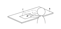
- FIG. 1 It is a figure which shows a mode when the image is moved according to user operation. It is a figure which shows an example when a household account book application image, a recipe search site, and a food mail order site are displayed when a wallet is placed on a table.
- FIG. 1 is a diagram illustrating a state in which the projector 100 according to an embodiment of the present technology is looked up from an obliquely downward direction.
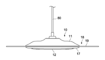
- FIG. 2 is a side view showing the first unit 10 included in the projection apparatus 100.
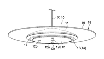
- FIG. 3 is a diagram illustrating a state where the first unit 10 included in the projection apparatus 100 is looked up obliquely from below.
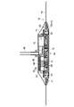
- FIG. 4 is a side sectional view of the first unit 10 included in the projection apparatus 100.
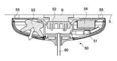
- FIG. 5 is a side sectional view of the second unit 50 included in the projection apparatus 100.
- the projection apparatus 100 (illumination apparatus 100) shown in these drawings is a type of projection apparatus 100 that is used by being suspended from a ceiling (a body to be installed).
- a general-purpose attachment 6 for a lighting device (see FIG. 5) that can be commonly used for different types of lighting devices is usually provided on the top surface 5 of the room.
- the fixture 6 is standardized according to JIS standards (Japanese Industrial Standards), and is provided on the top surface 5 for the purpose of supplying power to the lighting device and hanging the lighting device. Yes.
- the projection apparatus 100 according to the present embodiment is assumed to be used by being attached to such a general-purpose attachment 6. In the case of overseas, not the general-purpose mounting tool 6 but a dedicated mounting tool 6 may be used.
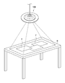
- FIG. 6 is a diagram showing a state when the image 7 is projected by the projection device 100.
- the projection apparatus 100 according to the present embodiment can project various images 7 on the upper surface of the table 8 using the upper surface of the table 8 as a screen.
- lighting device 100 includes lower first unit 10, upper second unit 50, and a connecting portion that connects first unit 10 and second unit 50. 80.
- the first unit 10 includes a first housing 11 and a lower plate 12 provided on the lower side of the first housing 11.
- the first housing 11 has a disk shape that is thin in the thickness direction and has a hollow inside.
- the lower plate 12 is thin in the thickness direction and has a solid disk shape.
- the lower plate 12 is attached to the first casing 11 so that the internal structure disposed in the first casing 11 cannot be seen from below.
- a gap 13 is formed between the outer peripheral surface of the lower plate 12 and the first housing 11, and an intake port 14 is formed by the gap 13.
- an exhaust port 15 is formed in the upper portion of the first housing 11 (see FIG. 4).
- the ring-shaped illumination part 17 is provided in the position of the lower part in the outer peripheral side of the 1st housing
- the illuminating unit 17 is configured by a plurality of LEDs (Light Emitting) Diode) (not shown) disposed inside the first housing 11.
- the illumination unit 17 may be configured by an incandescent bulb, a fluorescent tube, or the like.
- a treble speaker 18 (second speaker) is provided at a position on the outer peripheral side of the first housing 11.
- the treble speaker 18 outputs a sound in a high frequency region higher than a predetermined threshold (in charge of outputting a sound in the high frequency region).
- the predetermined threshold value serving as a reference for high and low frequencies is appropriately set in consideration of the influence of the sound pitch on the vibration of the first unit 10.
- the threshold value is set so that a high-frequency sound that does not adversely affect the projection unit 16 and / or the illumination unit 17 is output from the treble speaker 18.
- this threshold is set to about 1.5 kHz to 500 Hz. In the present embodiment, the threshold is set to 1 khz.
- the treble speaker 18 includes a tweeter plate 19 and a vibration mechanism 20 that vibrates the tweeter plate 19.
- the tweeter plate 19 is a ring-shaped plate member that is thin in the thickness direction, and is made of a transparent material such as acrylic resin.
- the tweeter plate 19 since the tweeter plate 19 is made of a transparent material, the design can be improved.
- the diaphragm may be made of a material other than a transparent material.
- the tweeter plate 19 has a diameter larger than the diameter of the first casing 11, a part on the inner peripheral side is disposed in the casing, and the other part is outside the first casing 11. (To explain in an easy-to-understand manner, the first casing 11 and the tweeter plate 19 have a UFO-like shape as a whole).
- the vibration mechanism 20 can vibrate the entire tweeter plate 19 by vibrating a part of the tweeter plate 19 on the inner peripheral side.
- the vibration direction (vertical direction) of the vibration surface is substantially the same as the projection direction (vertical direction) by the projection unit 16.
- the image 7 compared with the case where the image 7 projected by the projection unit 16 rolls (horizontal direction), the image 7 has a visual influence on the image 7 when the image 7 shakes vertically (vertical direction). It is considered small.
- the vibration direction of the vibration surface and the projection direction of the projection unit 16 are substantially the same direction. Therefore, even if the vibration of the tweeter plate 19 is transmitted to the projection unit 16 to some extent (since it is configured to output a high-frequency region sound, the vibration is hardly transmitted to the projection unit 16).
- the projection unit 16 will be pitched (one that has less visual effect). Therefore, the influence on the image 7 generated by the vibration of the high-frequency speaker 18 can be minimized.
- vibration direction of the vibration surface of the treble speaker 18 and the projection direction of the projection unit 16 are “substantially the same” is determined from the viewpoint of shaking of the projected image 7. For example, if the difference between the vibration direction and the projection direction is about +/ ⁇ 20 °, they are substantially the same (in this embodiment, the difference is 0 °).
- a microphone 21 for acquiring voice by the user is provided inside the first casing 11.
- two depth cameras 22 (see FIG. 4) and one visible light camera 23 (RGB) are arranged at the lower position of the first housing 11 toward the lower side. Camera) (see FIG. 8).
- the two depth cameras 22 are, for example, cameras for detecting the position of the table 8 in the depth direction, the position of the user's hand with respect to the table 8, the position of the object 9 (see FIG. 10) placed on the table 8. It is.
- One visible light camera 23 is a camera for identifying the object 9 placed on the table 8.
- the depth camera 22 is an infrared camera.
- the depth camera 22 may be configured by a visible light camera.
- openings 12b are formed at positions corresponding to the three cameras so as to penetrate the lower plate 12 in the vertical direction (see FIG. 3).
- two depth cameras 22 are provided to detect a hand operation (that is, a touch operation) on the image 7 displayed on the table 8.
- a touch sensor may be provided on the table 8. In this case, information from the touch sensor is transmitted to the projection apparatus 100 wirelessly or by wire.
- the projection apparatus 100 has two modes of a projection apparatus mode and an illumination apparatus 100 mode.
- the projection device mode is a mode in which the light from the illumination unit 17 is turned off and the projection unit 16 performs projection.
- the illumination device 100 mode is a mode in which the illumination unit 17 lights up and the projection unit 16 does not perform projection. That is, in the present embodiment, the projection device 100 can be used as either the projection device 100 or the illumination device 100.
- the projection device 100 When the projection device 100 according to the present embodiment detects a specific gesture operation of a hand by a user or a specific voice input to a microphone, the projection device 100 operates in either the projection device mode or the illumination device 100 mode in accordance with the input. It is configured to switch between. Note that switching between the projection apparatus mode and the illumination apparatus 100 mode may be performed by a remote controller.
- a cooling mechanism 40 for cooling the laser oscillator 28 (first heat source) and for cooling the APU 24 and the FPGA 26 is provided inside the first housing 11. Details of the cooling mechanism 40 will be described later with reference to FIG.
- the second unit 50 includes a second housing 51 having a hemispherical shape with the upper half cut off.
- a socket portion 52 for attaching the second unit 50 to the fixture 6 provided on the top surface 5 is provided at a position on the upper side in the center of the second housing 51.
- the socket part 52 includes two claw-shaped metal terminals (not shown) on the upper part of the socket part 52, and the projection apparatus 100 is attached to the attachment tool 6 by hooking the metal terminals against the attachment tool 6. Are electrically and physically connected to each other.
- a bass speaker 53 (first speaker) is provided inside the second casing 51 at a position outside the center (left side in FIG. 5).
- the bass speaker 53 outputs a sound in a low frequency region lower than a predetermined threshold (in charge of outputting a sound in the low frequency region). That is, in the present embodiment, the speaker is divided into two according to the level of the sound frequency.
- the threshold value that serves as a reference for the high and low frequencies is set to 1 kHz.
- the low-frequency speaker 53 that generates vibration due to the output of sound in the low-frequency region is a unit different from the first unit 10 in which the projection unit 16 is provided. Arranged in a certain second unit 50. Therefore, it can suppress that the image 7 projected by the projection part 16 shakes by the output of the sound of the bass speaker 53. Thereby, it is possible to prevent the user from feeling that the image 7 is difficult to see or uncomfortable because the image 7 projected by the projection unit 16 is shaken. it can.
- the vibration direction of the vibration surface (indicated by a white arrow in FIG. 5) is substantially the same as the projection direction (vertical direction) by the projection unit 16.
- the projection unit 16 shakes at that time (the one with less visual influence). Therefore, the influence on the image 7 caused by the vibration of the bass speaker 53 can be minimized.
- vibration direction of the vibration surface of the bass speaker 53 and the projection direction of the projection unit 16 are “substantially the same” is determined from the viewpoint of shaking of the projected image 7. For example, if the difference between the vibration direction and the projection direction is about +/ ⁇ 20 °, they are substantially the same (in this embodiment, the difference is 18 °).
- the bass speaker 53 is configured to output sound with a phase earlier than that of the treble speaker 18. Thereby, at the position of the user's ear (near the middle position between the upper surface of the projection device 100 and the table 8), the sound in the low frequency region generated from the low frequency speaker 53 and the sound in the high frequency region generated from the high frequency speaker 18 are generated. Synthesized appropriately.
- an AC / DC circuit 54 (AC: Alternating) that converts an AC voltage into a DC voltage is provided at a position opposite to the side where the bass speaker 53 is provided (on the right side in FIG. 5).
- Current DC Direct Current (power supply circuit) is provided.
- a generally heavy power circuit is disposed on the second unit 50 side (that is, on the base side).
- the second unit 50 side that is, the base side
- the first unit 10 side becomes lighter, so that the weight balance is improved and the projector 100 is stably attached to the top surface 5.
- the AC / DC circuit 54 is disposed on the second unit 50 side (that is, the base side), so that the AC / DC circuit 54 is disposed on the first unit 10.
- the first unit 10 can be easily reduced in thickness. As a result, the design of the first unit 10 can be improved.
- the bass speaker 53 which is generally heavy, is disposed on the second unit 50 side (that is, the base side), the second unit 50 side (that is, the base side).
- the first unit 10 side becomes lighter. Accordingly, the weight balance is improved, and the projection apparatus 100 can be stably installed on the ceiling.
- the weight of the AC / DC circuit 54 and the weight of the bass speaker 53 are substantially the same, and the balance in the left-right direction is also maintained.
- the bass speaker 53 is arranged on the second unit 50 side (that is, the base side), a speaker that outputs sounds of all frequencies is arranged in the first unit 10. Compared to the above, the thickness of the first unit 10 can be easily reduced. As a result, the design of the first unit 10 can be improved.
- a plurality of vibration control portions 55 are provided on the upper surface of the second casing 51 so as to protrude from the upper surface toward the ceiling (installed body side).
- the vibration control part 55 can be stably fixed to the top surface 5 while suppressing vibrations of the second unit 50 by contacting the ceiling at the upper part thereof. It is possible.
- the damping unit 55 is configured by an elastic body such as rubber having a predetermined elastic force.
- the shape of the damping unit 55 is a cylindrical shape, but the shape of the damping unit 55 can be changed as appropriate (for example, spherical, hemispherical, etc.).
- the vibration control unit 55 is disposed at a predetermined distance from the center of the second casing 51 (a position where the connecting unit 80 is provided) at a predetermined distance along the circumferential direction. .
- the stability of the second unit 50 with respect to the top surface 5 is higher when the distance from the center of the second housing 51 to the vibration control unit 55 is as far as possible. From such a viewpoint, in the example illustrated in FIG. 5, the vibration damping portion 55 is disposed at an outer position on the upper surface of the second housing 51.
- the number of vibration control units 55 is three in this embodiment.
- the stability of the second unit 50 with respect to the top surface 5 is further enhanced by the second casing 51 coming into contact with the top surface 5 at three points.
- the number of control units 1 is not limited to three, and may be four or five (at least three or more).
- the connecting portion 80 is provided so as to connect the center of the first unit 10 and the center of the second unit 50.
- the connecting portion 80 is a hollow cylindrical member (shaft) inside, and power and communication wirings are passed through the inside.
- the connection part 80 is comprised by the member which has more than fixed rigidity like a metal or resin, for example. That is, the connecting portion 80 can connect the first unit 10 and the second unit 50 to a rigid. Thereby, the first unit 10 is prevented from swaying due to, for example, the influence of wind, and the image 7 projected from the projection unit 16 can be prevented from swaying.
- connection part 80 may be comprised with elastic bodies, such as rubber
- the shaft has been described as an example of the connecting portion, but examples of the connecting portion include a cable, a wire, and a chain.
- FIG. 7 is a schematic diagram showing the cooling mechanism 40.
- the cooling mechanism 40 includes a first heat sink 41 for cooling the laser oscillator 28 (first heat source), an APU 24 and an FPGA 26 (second heat source: temperature higher than that of the first heat source).
- a second heat sink 42 for cooling the second heat sink 42 and an axial fan 43 interposed between the first heat sink 41 and the second heat sink 42.
- the cooling mechanism 40 includes a plurality of heat pipes 44 for transferring heat generated in the APU 24 and the FPGA 26 to the heat sink.
- the APU 24 and the FPGA 26 may rise to 100 ° or more, and the laser oscillator 28 may rise to about 45 °, for example. That is, the APU 24 and the FPGA 26 are heat sources having a temperature higher than that of the laser oscillator 28.
- the first heat sink 41 and the second heat sink 42 are configured by a plurality of radiating fins 41a and 42a which are arranged upright in the vertical direction and arranged at a predetermined interval.
- the laser oscillator 28 is disposed so as to enter the inside of the first heat sink 41.
- the heat pipe 44 is filled with a hydraulic fluid such as water in a reduced pressure state, and a wick for generating a capillary force is formed on the inner wall portion thereof.
- a hydraulic fluid such as water in a reduced pressure state
- a wick for generating a capillary force is formed on the inner wall portion thereof.
- One end portion 44a (evaporating portion 44a) of the heat pipe 44 is heated with the APU 24 and the FPGA 26 via the first heat diffusion plate 45 that diffuses the heat of the APU 24 and the second heat diffusion plate 46 that diffuses the heat of the FPGA 26. Are in contact.
- One end portion 44a (evaporating portion 44a) of the heat pipe 44 is disposed at a position sandwiched between the APU 24 and the FPGA 26 in the vertical direction.
- the APU substrate 25, the first heat diffusion plate 45, the FPGA 26, and the second heat diffusion plate 46 are integrally fixed by a method such as screwing.
- the other end 44 b (condensing part 44 b) of the heat pipe 44 is in contact with the second heat sink 42. Specifically, a hole having a size corresponding to the diameter of the heat pipe 44 is formed in the second heat sink 42 in the horizontal direction (the direction orthogonal to the direction in which the airflow is generated). The other end 44b of the second heat sink 42 is fitted.
- the heat pipe 44 is arranged such that the condensing part 44b of the heat pipe 44 is higher than the evaporation part 44a of the heat pipe 44.
- the hydraulic fluid evaporated in the evaporation part 44a can reach
- the hydraulic fluid condensed in the condenser 44b can smoothly reach the evaporator 44a (because the hydraulic fluid moves by gravity in addition to the capillary force). Therefore, the heat transfer efficiency by the heat pipe 44 can be improved.
- the number of heat pipes 44 is three in this embodiment, but this number can be changed as appropriate.
- the axial fan 43 generates an air flow toward the upper side in the axial direction (vertical direction), forcing the warm air in the first heat sink 41 and the second heat sink 42 to the outside of the first unit 10. Let it drain.
- the air inlet 14 is formed by the gap 13 between the first casing 11 and the lower plate 12 in the first unit 10 as described above.
- the exhaust port 15 is provided on the upper surface of the first housing 11.
- these heat sinks are arranged in the order of the first heat sink 41 and the second heat sink 42 from the upstream side of the airflow. This prevents the laser oscillator 28 from being exposed to a high temperature.
- the effect that the heat of the second heat sink 42 (high temperature) is not easily transmitted to the first heat sink 41 by interposing the axial fan 43 between the first heat sink 41 and the second heat sink 42. There is also. From this point of view as well, in this embodiment, the temperature of the laser oscillator 28 is prevented from rising.
- the first heat sink 41 corresponding to the low heat source (laser oscillator 28) is disposed at the upper position of the second heat sink 42 corresponding to the high heat source (APU 24 and FPGA 26).
- the axial fan 43 a natural airflow is further generated from the lower side to the upper side along the vertical direction.
- the heat dissipation effect of the cooling mechanism 40 is further improved.
- the axial fan 43 is disposed so as to be sandwiched between the first heat sink 41 and the second heat sink 42. Therefore, the noise generated from the axial fan 43 is absorbed by the first heat sink 41 and the second heat sink 42, and there is an advantage that the noise is reduced.
- FIG. 8 is a block diagram showing an electrical configuration of the projection apparatus 100.
- the projection apparatus 100 includes the projection unit 16, the illumination unit 17, the high tone speaker 18, the depth camera 22, the visible light camera 23, the axial fan 43, the low tone speaker 53, and the AC / DC circuit 54.
- a control unit 1, a storage unit 2, and a communication unit 3 are provided.
- the control unit 1, the storage unit 2, and the communication unit 3 are mounted on various substrates arranged inside the first unit 10.
- the control unit 1 includes the APU 24 and the FPGA 26 described above.
- the APU 24 comprehensively controls each unit of the projection apparatus 100.
- the FPGA 26 mainly executes image processing for projecting the image 7 in the projection unit 16.
- the control unit 1 executes various processes for reducing the shaking of the image 7 of the projection unit 16 and the flickering of the lighting unit 17 caused by the vibration of the bass speaker 53. This process will be described in detail later in the explanation of operation.
- the storage unit 2 includes a nonvolatile memory (for example, ROM (Read Only Memory)) in which various programs and various data are fixedly stored, and a volatile memory (as a work area of the control unit 1).
- ROM Read Only Memory
- RAM Random Access Memory
- the program may be read from a portable recording medium such as an optical disk or a semiconductor device, or may be downloaded from a server device on a network.
- the communication unit 35 is configured to be connectable to a network, and is configured to be able to communicate with other devices (for example, server devices) via the network.
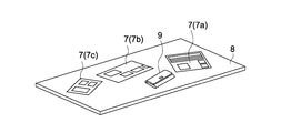
- FIG. 10 shows an example when the household account book application image 7a, the recipe search site 7b, and the food mail order site 7c are displayed when the wallet 9 is placed on the table 8.
- the control unit 1 When the depth camera 22 (detection unit) detects a specific gesture operation on the table 8 (for example, an operation of lowering the hand from the top to the bottom by a predetermined distance or more), the control unit 1 is output from the bass speaker 53. The process of lowering the volume of sound in the low frequency region is executed. As a result, the user can arbitrarily lower the volume of the bass speaker 53 by performing a gesture operation when the image 7 of the projection unit 16 shakes and the flickering of the illumination unit 17 is a concern. . That is, the user can arbitrarily suppress the shaking of the image 7 of the projection unit 16 and the flickering of the lighting unit 17.
- the control unit 1 determines whether the depth camera 22 (detection unit) detects another specific hand gesture operation on the table 8 (for example, an operation of raising the hand from below to above a predetermined distance).
- the control unit 1 detects another specific hand gesture operation on the table 8 (for example, an operation of raising the hand from below to above a predetermined distance)
- the control unit 1 determines whether the depth camera 22 (detection unit) detects another specific hand gesture operation on the table 8 (for example, an operation of raising the hand from below to above a predetermined distance)
- the control unit 1 detects another specific hand gesture operation on the table 8 (for example, an operation of raising the hand from below to above a predetermined distance)
- the control unit 1 detects another specific hand gesture operation on the table 8 (for example, an operation of raising the hand from below to above a predetermined distance) is detected.
- the control unit 1 When a specific gesture operation (for example, an operation of drawing x in space) is detected on the table 8 by the depth camera 22 (detection unit), the control unit 1 outputs a sound in a low-frequency region from the low-frequency speaker 53.
- the bass speaker 53 is controlled so as not to occur.
- the user can arbitrarily turn off the sound of the bass speaker 53 by performing a gesture operation when the image 7 of the projection unit 16 shakes and the flickering of the lighting unit 17 is a concern. . That is, the user can arbitrarily suppress the shaking of the image 7 of the projection unit 16 and the flickering of the lighting unit 17.
- the depth camera 22 detects another specific hand gesture operation on the table 8 (for example, a drawing operation in a space)
- a sound is output from the bass speaker 53.
- the bass speaker 53 is controlled. Accordingly, the user can arbitrarily output a sound from the bass speaker 53 by performing a gesture operation when the image 7 of the projection unit 16 is not shaken and the flickering of the illumination unit 17 is not concerned. it can.
- control unit 1 changes the volume of the bass speaker 53 but does not change the volume of the treble speaker 18.
- control unit 1 may change the volume of the treble speaker 18 in accordance with the change in the volume of the bass speaker 53 (the change in the volume of the treble speaker 18 may be less than the change in the volume of the bass speaker 53. it can).
- the projection apparatus 100 is provided with a vibration detection unit (for example, an acceleration sensor, an angular velocity sensor, etc.) that detects the vibration of the bass speaker 53.
- the vibration detection unit may be provided directly on the bass speaker 53 or may be provided indirectly at a place other than the bass speaker 53 (for example, the bass speaker in the second unit 50). 53, the connecting part 80, the first unit 10).
- the control unit 1 may estimate (detect) the vibration of the bass speaker 53 based on the volume of the bass speaker 53. In this case, since the control part 1 has a role as a vibration detection part, it is not necessary to provide a vibration detection part specially.
- the control unit 1 warns the user in accordance with the vibration detected (estimated) by the vibration detection unit.
- the warning is performed by the image 7 by the projection unit 16 (warning unit), sound from the speakers 18 and 53 (warning unit), and the like.
- the control unit 1 determines whether or not the vibration detected (estimated) by the vibration detection unit exceeds a predetermined vibration threshold.
- a warning is given to the user by the image 7 by the projection unit 16, sound from the speakers 18 and 53, and the like. Accordingly, when there is a possibility that the image 7 of the projection unit 16 is shaken or the light of the illumination unit 17 is flickering, a warning can be appropriately given to the user.
- the control unit 1 adjusts the amount of sound in the low frequency region output from the bass speaker 53 in accordance with the vibration detected (estimated) by the vibration detection unit. Specifically, the control unit 1 determines whether or not the vibration detected (estimated) by the vibration detection unit exceeds a predetermined vibration threshold. When the vibration exceeds the vibration threshold, the control unit 1 adjusts the volume so as to reduce the amount of sound in the low-frequency region output from the bass speaker 53 (including canceling the sound). .
- control unit 1 can automatically adjust the amount of sound in the low frequency region to automatically suppress the shaking of the image 7 of the projection unit 16 and the flickering of the lighting unit 17.
- control unit 1 may adjust the volume so as to increase the amount of sound in the low frequency region output from the bass speaker 53.
- control unit 1 controls the imaging unit so that the projection unit 16 projects the image 7 in a plurality of display modes including at least a still image display mode and a moving image display mode. And the control part 1 described above 3. according to the display mode. And 4.
- the vibration threshold value is controlled variably. Specifically, the control unit 1 controls the vibration threshold so that the vibration threshold in the still image mode is lower than the vibration threshold in the moving image display mode.
- the vibration threshold value in the still image display mode is set lower than the vibration threshold value in the moving image display mode.
- the volume is automatically adjusted even with a smaller vibration than in the moving image display mode (in the case of the above example 4).
- the vibration threshold value can be appropriately changed according to the display mode in this way.
- the projection device 100 includes both the projection unit 16 and the illumination unit 17 has been described.
- any one of these can be omitted (when the projection unit 16 is omitted, the device is the lighting device 100). That is, even if one of the projection unit 16 and the illumination unit 17 is omitted, the effect of reducing one of the shaking of the image 7 by the projection unit 16 and the flickering of the light by the illumination unit 17 can be achieved.
- the high-frequency speaker 18 is provided for the first unit 10 and the low-frequency speaker 53 is provided for the second unit 50.
- a speaker hereinafter referred to as an all-range speaker: first speaker
- the second unit 50 may be provided for the second unit 50 (in this case, the first unit 10 includes Does not have a speaker).
- the low frequency region sound (the main cause of the shaking of the image 7 and the flickering of the light) is output to a unit different from the unit provided with the projection unit 16 and the illumination unit 17.
- a range speaker will be provided. That is, also in the case of this example, the shaking of the image 7 by the projection unit 16 and the flickering of the light by the illumination unit 17 can be appropriately suppressed.
- a specific gesture operation for example, an operation of lowering the hand by a predetermined distance or more from the top to the bottom
- the control unit 1 executes a process of reducing the amount of sound corresponding to the low frequency region among all the frequency region sounds output from the all-range speaker.
- the all-range speaker is used. A process of increasing the amount of sound corresponding to the low frequency region out of all output frequency region sounds is executed.
- control boards such as the APU board 25 and the FPGA board 27 are provided for the first unit 10 has been described.
- these control substrates may be provided for the second unit 50.
- the heat pipe 44 and the second heat sink 42 are also provided for the second unit 50.
- the projection apparatus 100 may be installed on a floor, a side wall, a table, or the like.
- the position where the projection apparatus 100 is installed is not limited to indoors but may be outdoor.
- This technique can also take the following composition.
- a first unit having a projection unit for projecting an image;
- a second unit having a first speaker that outputs at least a sound in a low frequency region lower than a predetermined threshold;
- a connecting portion for connecting the first unit and the second unit;
- the second unit is positioned closer to the installation object than the first unit when the projection apparatus is installed on another installation object.
- Projection device (2)
- the projection apparatus according to (1) above, The first speaker is in charge of outputting a sound in a low frequency region lower than the predetermined threshold
- the first unit includes a second speaker in charge of outputting a sound in a high frequency region higher than the predetermined threshold.
- the first unit includes a lighting unit.
- the second unit further includes a power supply circuit.
- the projection apparatus according to any one of (1) to (4) above, The first speaker has a vibration surface that generates sound by vibration; The vibration direction of the vibration surface is substantially the same as the projection direction of the image by the projection unit.
- the projection apparatus according to (2) above, The second speaker has a vibration surface that generates sound by vibration, The vibration direction of the vibration surface is substantially the same as the projection direction of the image by the projection unit.
- a detection unit for detecting a user operation A projection apparatus further comprising: a control unit that adjusts an amount of sound in the low-frequency region output from the first speaker in accordance with the detected user operation.
- the control unit controls the first speaker so that the sound in the low frequency region is not output from the first speaker in response to the user operation.
- a warning section that warns the user;
- a control unit that controls the warning unit so as to warn a user in response to the detected vibration of the first speaker.
- the control unit determines whether or not the vibration of the first speaker exceeds a predetermined vibration threshold value, and controls the warning unit to warn the user when the vibration exceeds the vibration threshold value.
- Projection device (11) The projection apparatus according to any one of (1) to (10) above, A vibration detector for detecting vibrations of the first speaker; And a control unit that adjusts an amount of sound in the low-frequency region output from the first speaker in accordance with the detected vibration of the first speaker. (12) The projection device according to (11) above, The control unit determines whether or not the vibration of the first speaker exceeds a predetermined vibration threshold value. When the vibration exceeds the vibration threshold value, the low frequency region output from the first speaker is determined.
- a projection device that adjusts the volume to reduce the volume of sound.
- the control unit variably controls the vibration threshold.
- the control unit controls the projection unit to cause the projection unit to project an image in a plurality of display modes, and variably controls the vibration threshold according to the display mode.
- the second unit further includes a vibration damping unit that is provided on a surface on the object to be installed side so as to protrude from the surface toward the object to be installed, and that comes into contact with the object to be installed.
- the connecting portion is one of a shaft, a cable, a wire, and a chain.
Landscapes
- Physics & Mathematics (AREA)
- Engineering & Computer Science (AREA)
- Acoustics & Sound (AREA)
- Signal Processing (AREA)
- Health & Medical Sciences (AREA)
- Otolaryngology (AREA)
- General Physics & Mathematics (AREA)
- Projection Apparatus (AREA)
- Arrangement Of Elements, Cooling, Sealing, Or The Like Of Lighting Devices (AREA)
- Non-Portable Lighting Devices Or Systems Thereof (AREA)
- Transforming Electric Information Into Light Information (AREA)
Abstract
Le dispositif de projection de l'invention est muni d'une première unité, d'une seconde unité et d'une partie couplage. Ladite première unité possède une partie projection. Ladite seconde unité possède un premier haut-parleur qui émet en sortie au moins des sons d'une bande de basses fréquences plus basses qu'une valeur seuil prédéfinie, et est positionnée du côté d'une face de placement sur laquelle est placée le dispositif de projection. Ladite partie couplage couple ladite première unité et ladite seconde unité.
Applications Claiming Priority (2)
| Application Number | Priority Date | Filing Date | Title |
|---|---|---|---|
| JP2014-265937 | 2014-12-26 | ||
| JP2014265937A JP2016126114A (ja) | 2014-12-26 | 2014-12-26 | 投影装置及び照明装置 |
Publications (1)
| Publication Number | Publication Date |
|---|---|
| WO2016103564A1 true WO2016103564A1 (fr) | 2016-06-30 |
Family
ID=56149638
Family Applications (1)
| Application Number | Title | Priority Date | Filing Date |
|---|---|---|---|
| PCT/JP2015/005718 Ceased WO2016103564A1 (fr) | 2014-12-26 | 2015-11-17 | Dispositif de projection, et dispositif d'éclairage |
Country Status (2)
| Country | Link |
|---|---|
| JP (1) | JP2016126114A (fr) |
| WO (1) | WO2016103564A1 (fr) |
Cited By (1)
| Publication number | Priority date | Publication date | Assignee | Title |
|---|---|---|---|---|
| CN107355721A (zh) * | 2017-06-21 | 2017-11-17 | 太仓派欧技术咨询服务有限公司 | 一种多功能吊灯 |
Families Citing this family (5)
| Publication number | Priority date | Publication date | Assignee | Title |
|---|---|---|---|---|
| WO2018047262A1 (fr) * | 2016-09-08 | 2018-03-15 | マクセル株式会社 | Dispositif de fixation pour dispositif de projection d'image, et système de projection d'image utilisant ce dernier |
| JP7189495B2 (ja) * | 2018-09-25 | 2022-12-14 | 東芝ライテック株式会社 | 照明装置 |
| JP7424255B2 (ja) * | 2020-09-10 | 2024-01-30 | セイコーエプソン株式会社 | プロジェクター付き照明装置および照明装置 |
| US12149905B2 (en) * | 2021-02-22 | 2024-11-19 | Panasonic Intellectual Property Management Co., Ltd. | Speaker device |
| JP7777777B2 (ja) * | 2022-02-15 | 2025-12-01 | パナソニックIpマネジメント株式会社 | ペンダント灯 |
Citations (4)
| Publication number | Priority date | Publication date | Assignee | Title |
|---|---|---|---|---|
| JP2009224822A (ja) * | 2008-03-13 | 2009-10-01 | Odelic Co Ltd | スピーカ配設システム及びスピーカ装置 |
| JP2012186675A (ja) * | 2011-03-07 | 2012-09-27 | Sony Corp | 信号処理装置および信号処理方法 |
| JP2012227733A (ja) * | 2011-04-19 | 2012-11-15 | Onkyo Corp | 天井設置用スピーカーシステムおよびこれを用いる照明装置 |
| WO2014171148A1 (fr) * | 2013-04-18 | 2014-10-23 | パナソニック株式会社 | Dispositif d'affichage vidéo par projection |
-
2014
- 2014-12-26 JP JP2014265937A patent/JP2016126114A/ja active Pending
-
2015
- 2015-11-17 WO PCT/JP2015/005718 patent/WO2016103564A1/fr not_active Ceased
Patent Citations (4)
| Publication number | Priority date | Publication date | Assignee | Title |
|---|---|---|---|---|
| JP2009224822A (ja) * | 2008-03-13 | 2009-10-01 | Odelic Co Ltd | スピーカ配設システム及びスピーカ装置 |
| JP2012186675A (ja) * | 2011-03-07 | 2012-09-27 | Sony Corp | 信号処理装置および信号処理方法 |
| JP2012227733A (ja) * | 2011-04-19 | 2012-11-15 | Onkyo Corp | 天井設置用スピーカーシステムおよびこれを用いる照明装置 |
| WO2014171148A1 (fr) * | 2013-04-18 | 2014-10-23 | パナソニック株式会社 | Dispositif d'affichage vidéo par projection |
Cited By (1)
| Publication number | Priority date | Publication date | Assignee | Title |
|---|---|---|---|---|
| CN107355721A (zh) * | 2017-06-21 | 2017-11-17 | 太仓派欧技术咨询服务有限公司 | 一种多功能吊灯 |
Also Published As
| Publication number | Publication date |
|---|---|
| JP2016126114A (ja) | 2016-07-11 |
Similar Documents
| Publication | Publication Date | Title |
|---|---|---|
| WO2016103564A1 (fr) | Dispositif de projection, et dispositif d'éclairage | |
| JP6854859B2 (ja) | 照明装置 | |
| JP2020005297A (ja) | 照明兼ラウドスピーカードライバー装置 | |
| CA2855185C (fr) | Dispositif de visualisation d'images projetees | |
| US20100316247A1 (en) | Loudspeaker and alarm with luminous element | |
| CN101976013A (zh) | 具有消除激光散斑的投影机 | |
| JP6594521B2 (ja) | 照明装置 | |
| CN107250930A (zh) | 带有集成扬声器和/或声音检测系统的led灯具 | |
| US10613423B2 (en) | Image and light projection | |
| CN107110450A (zh) | 照明装置 | |
| JPWO2019012704A1 (ja) | 照明装置 | |
| JP2011164170A (ja) | 投射型表示装置 | |
| CN108884989B (zh) | 电子设备和照明系统 | |
| JP6321148B2 (ja) | 投写型映像表示装置 | |
| US8313200B2 (en) | Light source apparatus and projection device | |
| US20070146651A1 (en) | Projector with rotatable lens module | |
| JP2016071037A (ja) | 壁掛け式プロジェクタ装置の取り付け部材とそれを用いたプロジェクタ装置 | |
| US20050200816A1 (en) | Control method for cooling a projection display | |
| WO2016162913A1 (fr) | Dispositif d'éclairage | |
| JP2015225213A (ja) | 画像投射装置およびその制御プログラム | |
| CN107143796A (zh) | 动感音乐led照明灯 | |
| JP3224977U (ja) | 取り付けが容易な音響懐中電灯 | |
| CN209355105U (zh) | 可显示吊顶式灯具 | |
| WO2017169066A1 (fr) | Dispositif électronique | |
| JP6960599B2 (ja) | 照明装置、及び照明器具 |
Legal Events
| Date | Code | Title | Description |
|---|---|---|---|
| 121 | Ep: the epo has been informed by wipo that ep was designated in this application |
Ref document number: 15872142 Country of ref document: EP Kind code of ref document: A1 |
|
| NENP | Non-entry into the national phase |
Ref country code: DE |
|
| 122 | Ep: pct application non-entry in european phase |
Ref document number: 15872142 Country of ref document: EP Kind code of ref document: A1 |