WO2016103597A1 - Appareil de commande - Google Patents
Appareil de commande Download PDFInfo
- Publication number
- WO2016103597A1 WO2016103597A1 PCT/JP2015/006076 JP2015006076W WO2016103597A1 WO 2016103597 A1 WO2016103597 A1 WO 2016103597A1 JP 2015006076 W JP2015006076 W JP 2015006076W WO 2016103597 A1 WO2016103597 A1 WO 2016103597A1
- Authority
- WO
- WIPO (PCT)
- Prior art keywords
- state
- cylinder
- control value
- ecu
- fuel
- Prior art date
- Legal status (The legal status is an assumption and is not a legal conclusion. Google has not performed a legal analysis and makes no representation as to the accuracy of the status listed.)
- Ceased
Links
Images




Classifications
-
- F—MECHANICAL ENGINEERING; LIGHTING; HEATING; WEAPONS; BLASTING
- F02—COMBUSTION ENGINES; HOT-GAS OR COMBUSTION-PRODUCT ENGINE PLANTS
- F02D—CONTROLLING COMBUSTION ENGINES
- F02D13/00—Controlling the engine output power by varying inlet or exhaust valve operating characteristics, e.g. timing
- F02D13/02—Controlling the engine output power by varying inlet or exhaust valve operating characteristics, e.g. timing during engine operation
- F02D13/0203—Variable control of intake and exhaust valves
- F02D13/0207—Variable control of intake and exhaust valves changing valve lift or valve lift and timing
- F02D13/0211—Variable control of intake and exhaust valves changing valve lift or valve lift and timing the change of valve timing is caused by the change in valve lift, i.e. both valve lift and timing are functionally related
-
- F—MECHANICAL ENGINEERING; LIGHTING; HEATING; WEAPONS; BLASTING
- F02—COMBUSTION ENGINES; HOT-GAS OR COMBUSTION-PRODUCT ENGINE PLANTS
- F02D—CONTROLLING COMBUSTION ENGINES
- F02D41/00—Electrical control of supply of combustible mixture or its constituents
- F02D41/30—Controlling fuel injection
- F02D41/38—Controlling fuel injection of the high pressure type
- F02D41/40—Controlling fuel injection of the high pressure type with means for controlling injection timing or duration
- F02D41/401—Controlling injection timing
-
- F—MECHANICAL ENGINEERING; LIGHTING; HEATING; WEAPONS; BLASTING
- F02—COMBUSTION ENGINES; HOT-GAS OR COMBUSTION-PRODUCT ENGINE PLANTS
- F02D—CONTROLLING COMBUSTION ENGINES
- F02D13/00—Controlling the engine output power by varying inlet or exhaust valve operating characteristics, e.g. timing
- F02D13/02—Controlling the engine output power by varying inlet or exhaust valve operating characteristics, e.g. timing during engine operation
- F02D13/0203—Variable control of intake and exhaust valves
- F02D13/0215—Variable control of intake and exhaust valves changing the valve timing only
-
- F—MECHANICAL ENGINEERING; LIGHTING; HEATING; WEAPONS; BLASTING
- F02—COMBUSTION ENGINES; HOT-GAS OR COMBUSTION-PRODUCT ENGINE PLANTS
- F02D—CONTROLLING COMBUSTION ENGINES
- F02D35/00—Controlling engines, dependent on conditions exterior or interior to engines, not otherwise provided for
- F02D35/02—Controlling engines, dependent on conditions exterior or interior to engines, not otherwise provided for on interior conditions
-
- F—MECHANICAL ENGINEERING; LIGHTING; HEATING; WEAPONS; BLASTING
- F02—COMBUSTION ENGINES; HOT-GAS OR COMBUSTION-PRODUCT ENGINE PLANTS
- F02D—CONTROLLING COMBUSTION ENGINES
- F02D41/00—Electrical control of supply of combustible mixture or its constituents
- F02D41/02—Circuit arrangements for generating control signals
- F02D41/04—Introducing corrections for particular operating conditions
- F02D41/10—Introducing corrections for particular operating conditions for acceleration
-
- F—MECHANICAL ENGINEERING; LIGHTING; HEATING; WEAPONS; BLASTING
- F02—COMBUSTION ENGINES; HOT-GAS OR COMBUSTION-PRODUCT ENGINE PLANTS
- F02D—CONTROLLING COMBUSTION ENGINES
- F02D41/00—Electrical control of supply of combustible mixture or its constituents
- F02D41/24—Electrical control of supply of combustible mixture or its constituents characterised by the use of digital means
- F02D41/2406—Electrical control of supply of combustible mixture or its constituents characterised by the use of digital means using essentially read only memories
- F02D41/2409—Addressing techniques specially adapted therefor
- F02D41/2422—Selective use of one or more tables
-
- F—MECHANICAL ENGINEERING; LIGHTING; HEATING; WEAPONS; BLASTING
- F02—COMBUSTION ENGINES; HOT-GAS OR COMBUSTION-PRODUCT ENGINE PLANTS
- F02D—CONTROLLING COMBUSTION ENGINES
- F02D41/00—Electrical control of supply of combustible mixture or its constituents
- F02D41/30—Controlling fuel injection
- F02D41/32—Controlling fuel injection of the low pressure type
- F02D41/36—Controlling fuel injection of the low pressure type with means for controlling distribution
- F02D41/365—Controlling fuel injection of the low pressure type with means for controlling distribution with means for controlling timing and distribution
-
- F—MECHANICAL ENGINEERING; LIGHTING; HEATING; WEAPONS; BLASTING
- F02—COMBUSTION ENGINES; HOT-GAS OR COMBUSTION-PRODUCT ENGINE PLANTS
- F02D—CONTROLLING COMBUSTION ENGINES
- F02D41/00—Electrical control of supply of combustible mixture or its constituents
- F02D41/30—Controlling fuel injection
- F02D41/38—Controlling fuel injection of the high pressure type
- F02D41/40—Controlling fuel injection of the high pressure type with means for controlling injection timing or duration
- F02D41/402—Multiple injections
-
- F—MECHANICAL ENGINEERING; LIGHTING; HEATING; WEAPONS; BLASTING
- F02—COMBUSTION ENGINES; HOT-GAS OR COMBUSTION-PRODUCT ENGINE PLANTS
- F02D—CONTROLLING COMBUSTION ENGINES
- F02D43/00—Conjoint electrical control of two or more functions, e.g. ignition, fuel-air mixture, recirculation, supercharging or exhaust-gas treatment
-
- F—MECHANICAL ENGINEERING; LIGHTING; HEATING; WEAPONS; BLASTING
- F02—COMBUSTION ENGINES; HOT-GAS OR COMBUSTION-PRODUCT ENGINE PLANTS
- F02D—CONTROLLING COMBUSTION ENGINES
- F02D45/00—Electrical control not provided for in groups F02D41/00 - F02D43/00
-
- F—MECHANICAL ENGINEERING; LIGHTING; HEATING; WEAPONS; BLASTING
- F02—COMBUSTION ENGINES; HOT-GAS OR COMBUSTION-PRODUCT ENGINE PLANTS
- F02D—CONTROLLING COMBUSTION ENGINES
- F02D1/00—Controlling fuel-injection pumps, e.g. of high pressure injection type
- F02D1/16—Adjustment of injection timing
- F02D1/162—Adjustment of injection timing by mechanical means dependent on engine speed for angular adjustment of driving and driven shafts
-
- F—MECHANICAL ENGINEERING; LIGHTING; HEATING; WEAPONS; BLASTING
- F02—COMBUSTION ENGINES; HOT-GAS OR COMBUSTION-PRODUCT ENGINE PLANTS
- F02D—CONTROLLING COMBUSTION ENGINES
- F02D41/00—Electrical control of supply of combustible mixture or its constituents
- F02D41/0002—Controlling intake air
- F02D2041/001—Controlling intake air for engines with variable valve actuation
-
- F—MECHANICAL ENGINEERING; LIGHTING; HEATING; WEAPONS; BLASTING
- F02—COMBUSTION ENGINES; HOT-GAS OR COMBUSTION-PRODUCT ENGINE PLANTS
- F02D—CONTROLLING COMBUSTION ENGINES
- F02D2200/00—Input parameters for engine control
- F02D2200/02—Input parameters for engine control the parameters being related to the engine
- F02D2200/021—Engine temperature
-
- F—MECHANICAL ENGINEERING; LIGHTING; HEATING; WEAPONS; BLASTING
- F02—COMBUSTION ENGINES; HOT-GAS OR COMBUSTION-PRODUCT ENGINE PLANTS
- F02D—CONTROLLING COMBUSTION ENGINES
- F02D2250/00—Engine control related to specific problems or objectives
- F02D2250/12—Timing of calculation, i.e. specific timing aspects when calculation or updating of engine parameter is performed
-
- F—MECHANICAL ENGINEERING; LIGHTING; HEATING; WEAPONS; BLASTING
- F02—COMBUSTION ENGINES; HOT-GAS OR COMBUSTION-PRODUCT ENGINE PLANTS
- F02D—CONTROLLING COMBUSTION ENGINES
- F02D2250/00—Engine control related to specific problems or objectives
- F02D2250/38—Control for minimising smoke emissions, e.g. by applying smoke limitations on the fuel injection amount
-
- F—MECHANICAL ENGINEERING; LIGHTING; HEATING; WEAPONS; BLASTING
- F02—COMBUSTION ENGINES; HOT-GAS OR COMBUSTION-PRODUCT ENGINE PLANTS
- F02D—CONTROLLING COMBUSTION ENGINES
- F02D41/00—Electrical control of supply of combustible mixture or its constituents
- F02D41/02—Circuit arrangements for generating control signals
- F02D41/04—Introducing corrections for particular operating conditions
- F02D41/045—Detection of accelerating or decelerating state
-
- Y—GENERAL TAGGING OF NEW TECHNOLOGICAL DEVELOPMENTS; GENERAL TAGGING OF CROSS-SECTIONAL TECHNOLOGIES SPANNING OVER SEVERAL SECTIONS OF THE IPC; TECHNICAL SUBJECTS COVERED BY FORMER USPC CROSS-REFERENCE ART COLLECTIONS [XRACs] AND DIGESTS
- Y02—TECHNOLOGIES OR APPLICATIONS FOR MITIGATION OR ADAPTATION AGAINST CLIMATE CHANGE
- Y02T—CLIMATE CHANGE MITIGATION TECHNOLOGIES RELATED TO TRANSPORTATION
- Y02T10/00—Road transport of goods or passengers
- Y02T10/10—Internal combustion engine [ICE] based vehicles
- Y02T10/12—Improving ICE efficiencies
-
- Y—GENERAL TAGGING OF NEW TECHNOLOGICAL DEVELOPMENTS; GENERAL TAGGING OF CROSS-SECTIONAL TECHNOLOGIES SPANNING OVER SEVERAL SECTIONS OF THE IPC; TECHNICAL SUBJECTS COVERED BY FORMER USPC CROSS-REFERENCE ART COLLECTIONS [XRACs] AND DIGESTS
- Y02—TECHNOLOGIES OR APPLICATIONS FOR MITIGATION OR ADAPTATION AGAINST CLIMATE CHANGE
- Y02T—CLIMATE CHANGE MITIGATION TECHNOLOGIES RELATED TO TRANSPORTATION
- Y02T10/00—Road transport of goods or passengers
- Y02T10/10—Internal combustion engine [ICE] based vehicles
- Y02T10/40—Engine management systems
Definitions
- the present disclosure relates to a control device that controls an internal combustion engine that is mounted on a vehicle and directly injects fuel into a cylinder.
- ⁇ Factors for PM generation and PN increase include fuel adhesion and inhomogeneous fuel in the cylinder. That is, by directly injecting fuel into the cylinder, the fuel adheres to the cylinder and piston in a liquid state. In addition, if the fuel and air are not sufficiently mixed in the cylinder, the fuel is locally rich in the cylinder. Therefore, as countermeasures against the generation of PM and the increase of PN in an in-cylinder internal combustion engine, it is effective to suppress adhesion of liquid fuel in the cylinder and promote mixing of fuel and air.
- Patent Document 1 discloses a control device for an in-cylinder injection type internal combustion engine that changes the setting of the operation of the internal combustion engine in order to suppress adhesion of liquid fuel in the cylinder. Specifically, the control device described in Patent Literature 1 reduces the fuel adhering to the cylinder in a liquid state by temporarily changing the fuel injection timing.
- control device of Patent Document 1 the influence of the state of the internal combustion engine such as the temperature is not considered in the change of the fuel injection timing. Since the temperature of the internal combustion engine has a great influence on the generation of PM and the increase of PN, it is considered that the control device of Patent Document 1 cannot sufficiently suppress the generation of PM and the increase of PN from this viewpoint.
- This disclosure is intended to provide a control device for an internal combustion engine that is suitable for the state of the internal combustion engine and can suppress the generation of particulate matter.
- the operating state of the internal combustion engine is in the form of particles discharged by the combustion of fuel in the cylinder.
- a PM / PN emission determination unit that determines whether or not a substance is in a PM / PN emission state that increases compared to other operating states, and a fuel injection timing, a fuel injection frequency, a fuel injection pressure, and an intake valve timing of the internal combustion engine
- a control value calculation unit that calculates a control value of an actuator that adjusts at least one of the exhaust valve timing.
- the control value calculation unit is a state in which particulate matter is more likely to be generated than in other states, and among the plurality of PM / PN generation states in which the generation factors of the particulate matter are different from each other, There is an in-cylinder state estimation unit that estimates to which state the state belongs. Further, when it is determined that the operating state of the internal combustion engine is the PM / PN emission state, the control value calculation unit determines the PM ⁇ PN according to the PM / PN generation state estimated to belong to the state in the cylinder. A control value is calculated so as to eliminate the PN generation state.
- the PM / PN generation is performed according to the PM / PN generation state estimated to belong to the state in the cylinder.
- a control value of an actuator that adjusts the fuel injection timing and the like is calculated so as to eliminate the state. Therefore, PM / PN suppression suitable for the state of the internal combustion engine can be performed.
- control device for an internal combustion engine that can perform PM / PN suppression suitable for the state of the internal combustion engine.
- FIG. 1 is a schematic configuration diagram of a drive system to which an ECU according to an embodiment of the present disclosure is applied.
- FIG. 2 is a control block diagram for explaining functional blocks of the ECU shown in FIG.
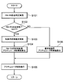
- FIG. 3 is a flowchart of a base routine executed by the ECU according to the embodiment of the present disclosure.
- FIG. 4 is a flowchart showing a process flow in the PM / PN emission determination shown in FIG.
- FIG. 5 is a time chart showing an example of driving states of the vehicle and the engine.
- FIG. 6 is a flowchart showing the flow of processing in the in-cylinder state estimation shown in FIG. FIG.
- FIG. 7 is a diagram showing a cold map.
- FIG. 8 is a diagram showing a warm map.
- FIG. 9 is a flowchart showing the flow of processing in calculating the actuator control value for PM / PN suppression control shown in FIG.
- FIG. 10 is a time chart showing an example of control by the ECU when the in-cylinder state is the WET state.
- FIG. 11 is a time chart showing an example of control by the ECU when the state in the cylinder is a heterogeneous state.
- FIG. 12 is a time chart showing an example of control by the ECU when the state in the cylinder is a high temperature state.
- the ECU 24 is applied to a vehicle drive system.
- the ECU 24 is mainly composed of a microcomputer. First, the configuration of the engine 1 that is the control target of the ECU 24 will be described.
- the engine 1 is an in-cylinder injection internal combustion engine and has a plurality of cylinders 50. In FIG. 1, only one cylinder 50 is illustrated, but actually, a plurality of cylinders 50 are arranged side by side. A piston 56 that reciprocates in the vertical direction is disposed inside each cylinder 50. A combustion chamber 54 is formed between the upper inner wall surface of each cylinder 50 and the piston 56.
- the engine 1 includes an intake pipe 2 that sucks combustion air from the outside, and an exhaust pipe 20 that guides exhaust gas discharged from the engine 1 to the outside.
- a filter-like air cleaner 3 for removing foreign substances from the passing air is provided.
- An air flow meter 4 for detecting the flow rate of the sucked air is provided on the downstream side of the air cleaner 3.
- a throttle valve 6 that opens and closes the flow path inside the intake pipe 2 is provided on the downstream side of the air flow meter 4.
- the throttle valve 6 is driven by a DC motor 5 and its opening (throttle opening) can be adjusted.
- the throttle opening is detected by a throttle sensor 7.
- a surge tank 8 is provided on the downstream side of the throttle valve 6.
- the surge tank 8 is provided with an intake pipe pressure sensor 9 for detecting the intake pipe pressure.
- An intake manifold 10 that introduces air into each cylinder 50 is connected between the surge tank 8 and the intake port 51 of each cylinder 50.
- the engine 1 has an intake valve 28 that opens and closes between the intake port 51 and the combustion chamber 54.
- the engine 1 also has an exhaust valve 29 that opens and closes between the exhaust port 52 and the combustion chamber 54.
- the intake valve 28 is provided with a variable valve timing mechanism 30 that adjusts the valve timing.
- the exhaust valve 29 is provided with a variable valve timing mechanism 31 for adjusting the valve timing.
- the fuel injection valve 16 In the vicinity of the intake valve 28 of each cylinder 50 of the engine 1, the fuel injection valve 16 is attached so as to face the combustion chamber 54.
- a delivery pipe 14 is connected to the fuel injection valve 16.
- the delivery pipe 14 extends to the fuel tank 11 via the high-pressure pump 13.
- the fuel injection valve 16 opens in response to a control signal output from the ECU 24 and directly injects fuel supplied from the fuel tank 11 and adjusted to a predetermined pressure by the high-pressure pump 13 into the combustion chamber 54 in each cylinder 50. To do.
- the pressure of the fuel supplied to the fuel injection valve 16 is detected by a fuel pressure sensor 15 provided on the upstream side of the fuel injection valve 16.
- a spark plug 17 is attached to the upper part of the combustion chamber 54 in each cylinder 50.
- the spark plug 17 performs spark discharge and ignites an air-fuel mixture composed of fuel and air.
- a knock sensor 25, a coolant temperature sensor 18, and a crank angle sensor 19 are attached to the cylinder block of the engine 1.
- Knock sensor 25 detects knocking of engine 1 and outputs a signal corresponding to the detection.
- the cooling water temperature sensor 18 detects the temperature of the cooling water that cools the engine, and outputs a signal corresponding to the detection.
- the crank angle sensor 19 detects the rotation of the crankshaft 58 for each predetermined crank angle and outputs a signal corresponding to the detection.
- the ECU 24 receives signals output from the knock sensor 25, the coolant temperature sensor 18, and the crank angle sensor 19, and uses them for controlling the engine 1. For example, the ECU 24 performs calculation based on the output signal of the crank angle sensor 19 to detect the crank angle and the engine rotation speed.
- the exhaust pipe 20 of the engine 1 is provided with an upstream catalyst 21 and a downstream catalyst 22 for purifying exhaust gas generated by the combustion of fuel in the cylinder 50. Further, an exhaust gas sensor 23 that detects an air-fuel ratio of the exhaust gas and the like is provided on the upstream side of the upstream catalyst 21.
- the vehicle driver accelerates the vehicle by depressing an accelerator pedal 26 provided in the vehicle.
- the amount of depression of the accelerator pedal 26 is detected by an accelerator pedal sensor 27.
- the accelerator pedal sensor 27 outputs a signal corresponding to the detected accelerator opening.
- the ECU 24 that has received the signal injects an amount of fuel corresponding to the accelerator opening from the fuel injection valve 16 to increase the amount of fuel combusted in the combustion chamber 54 in the cylinder 50, thereby bringing the vehicle into an acceleration state. .
- the ECU 24 receives signals output from various sensors as described above, and executes various control routines stored in a built-in ROM (storage medium). Thereby, the ECU 24 determines the amount of fuel injected by the fuel injection valve 16, the fuel injection timing, the fuel pressure by the high pressure pump 13, the opening and closing timing of the intake valve 28 and the exhaust valve 29, the ignition timing by the spark plug 17, and the like. Control is performed according to the operating state of the engine 1.
- FIG. 2 shows the ECU 24 as a functional control block diagram.
- the ECU 24 includes a PM / PN discharge determination unit 40, a control value calculation unit 46, and an actuator adjustment unit 44.
- the PM / PN emission determination unit 40 determines whether or not the operating state of the engine 1 is a PM / PN emission state in which particulate matter discharged by the combustion of fuel in the cylinder 50 increases as compared with other operating states. This is a part for determining. Specifically, the PM / PN emission determination unit 40 reads the accelerator opening detected by the accelerator pedal sensor 27 and the fuel injection amount calculated from the detected value of the fuel pressure sensor 15, and from these values the vehicle It is determined whether or not the vehicle is in an acceleration state. This is because there is a strong correlation between the acceleration state of the vehicle and the particulate matter to be discharged, and it is determined that the operation state of the engine 1 is in the PM / PN emission state when the vehicle is in the acceleration state. Because it can.
- whether or not the vehicle is in an acceleration state is determined based on the accelerator opening and the fuel injection amount, but the present disclosure is not limited to this. That is, it is determined whether or not the vehicle is in an acceleration state by using other indicators that are correlated with the acceleration state of the vehicle, such as the throttle opening degree, the intake air amount, the rotational speed and load of the engine 1, the vehicle speed, Is also possible.
- the control value calculation unit 46 includes a normal control value calculation unit 42 (hereinafter referred to as “normal calculation unit 42”) and a PM / PN suppression control control value calculation unit 43 (hereinafter referred to as “suppression calculation unit 43”). ”).
- the normal calculation unit 42 calculates control values for controlling the actuators of the fuel injection valve 16, the high-pressure pump 13, and the variable valve timing mechanisms 30 and 31 when PM / PN emission described later is not specifically suppressed. It is a part to do.
- the suppression calculation unit 43 is a part that calculates control values for controlling the actuators when PM / PN emission is suppressed.
- the suppression calculation unit 43 includes an in-cylinder state estimation unit 43A, an in-cylinder state control value calculation unit 43B, and a selection unit 43F.
- the in-cylinder state estimating unit 43A is a part that estimates the state in the cylinder 50 of the engine 1. Specifically, the in-cylinder state estimation unit 43A reads the rotation speed of the engine 1, the load of the engine 1, and the coolant temperature of the engine 1, and from these values, the state in the cylinder 50 is “WET state”, “inhomogeneous”. It is estimated which of the three PM / PN generation states of “state” and “high temperature state” belongs to.
- the “WET state” is a state in which the fuel is liable to be present in the cylinder 50 in a liquid state as compared with the “heterogeneous state” and the “high temperature state”, and as a result, generation of particulate matter is a concern. Further, in the “heterogeneous state”, the fuel concentration in the cylinder 50 is likely to be non-homogeneous compared to the “WET state” and the “high temperature state”, and as a result, the generation of particulate matter is a concern. It is.
- the “high temperature state” is a state in which the temperature in the cylinder 50 is likely to be higher than the “WET state” and the “heterogeneous state”, and as a result, the generation of particulate matter is a concern.
- the state in the cylinder 50 is estimated based on the rotation speed, load, and cooling water temperature of the engine 1, but the present disclosure is not limited to this. That is, it is possible to make the determination using other indexes that have a correlation with the state in the cylinder 50, such as the throttle opening, the accelerator opening, the vehicle speed, the fuel injection amount, and the intake air amount.
- the in-cylinder state control value calculation unit 43B includes a WET state control value calculation unit 43B1, a heterogeneous state control value calculation unit 43B2, and a high temperature state control value calculation unit 43B3.
- the WET state control value calculation unit 43B1 controls the actuators of the fuel injection valve 16, the high pressure pump 13, and the variable valve timing mechanisms 30 and 31 when it is estimated that the state in the cylinder 50 is the WET state. This is a part for calculating the control value.
- the control value calculation unit 43B2 for the inhomogeneous state calculates a control value for controlling each actuator when it is estimated that the state in the cylinder 50 is the inhomogeneous state.
- the high temperature state control value calculation unit 43B3 calculates a control value for controlling each of the actuators when it is estimated that the state in the cylinder 50 is a high temperature state.
- the selection unit 43F is calculated by the WET state control value calculation unit 43B1, the heterogeneous state control value calculation unit 43B2, and the high temperature state control value calculation unit 43B3 based on the estimation result in the in-cylinder state estimation unit 43A. One of the control values is selected.
- the ECU 24 further includes a selection unit 41.
- the selection unit 41 selects a control value calculated by one of the normal calculation unit 42 and the suppression calculation unit 43 based on the determination result in the PM / PN emission determination unit 40. That is, when it is determined that the operation state of the engine 1 is not the PM / PN emission state, the selection unit 41 selects the control value calculated by the normal calculation unit 42. On the other hand, when it is determined that the operation state of the engine 1 is the PM / PN emission state, the selection unit 41 selects the control value calculated by the suppression calculation unit 43.
- the actuator adjustment unit 44 adjusts each actuator based on the control value calculated by the control value calculation unit 46.
- the actuator adjustment unit 44 includes a fuel injection timing / injection number adjustment unit 44A, a fuel injection pressure adjustment unit 44B, an intake variable valve timing adjustment unit 44C, and an exhaust variable valve timing adjustment unit 44D.
- the fuel injection timing / injection frequency adjustment unit 44A adjusts the fuel injection valve 16 so that the fuel injection timing and the injection frequency become the control values selected by the selection unit 41.
- the fuel injection pressure adjustment unit 44B adjusts the high-pressure pump 13 so that the fuel injection pressure becomes the control value selected by the selection unit 41.
- the intake variable valve timing adjustment unit 44C adjusts the variable valve timing mechanism 30 so that the valve timing of the intake valve 28 becomes the control value selected by the selection unit 41.
- the exhaust variable valve timing adjustment unit 44D adjusts the variable valve timing mechanism 31 so that the valve timing of the exhaust valve 29 becomes the control value selected by the selection unit 41.
- the ECU 24 performs processing according to the base routine shown in FIG. Prior to the execution of the base routine, the ECU 24 performs an initialization process when the ignition switch of the vehicle is turned on. The ECU 24 sets “0” to a PM / PN discharge state flag xpn, which will be described later, and a calculated value in the initialization process.
- step S101 the ECU 24 determines whether or not the operating state of the engine 1 is a PM / PN discharge state based on the values of the accelerator opening and the fuel injection amount.
- FIG. 4 shows a subroutine for determination in step S101 of the base routine.
- the ECU 24 repeatedly executes this subroutine at a predetermined cycle (for example, 10 ms cycle).
- FIG. 5 shows the driving state of the vehicle and the engine 1. Here, an example is shown in which the vehicle traveling at a constant speed is accelerated halfway and then travels at a constant speed again. .
- step S201 in FIG. 4 the ECU 24 rotates the speed Ne of the engine 1, the load ce, the cycle and the accelerator opening accele [i, i-5] five cycles before, and the fuel injection five cycles before the cycle.
- the quantity quantity [i, i-5] and the PM / PN emission state flag xpn [i-1] one cycle before are read.
- the engine speed Ne and the load ce of the engine 1 are referred to as “engine speed Ne” and “engine load ce”, respectively.
- step S202 the ECU 24 determines whether or not the engine speed Ne is within a predetermined range ( ⁇ ⁇ Ne ⁇ ⁇ ).
- the ECU 24 proceeds to step S203.
- step S203 the ECU 24 determines whether or not the engine load ce is within a predetermined range ( ⁇ ⁇ ce ⁇ ⁇ ).
- the ECU 24 proceeds to step S205.
- step S205 the ECU 24 calculates an accelerator opening change amount daccele from five cycles before to the cycle. After calculating the accelerator opening change amount daccele, the ECU 24 proceeds to step S206.
- step S206 the ECU 24 calculates a fuel injection amount change amount dquantity from five cycles before to the cycle. After calculating the fuel injection amount change amount dquantity, the ECU 24 proceeds to step S207.
- step S207 the ECU 24 determines whether or not “0” is set in the PM / PN discharge state flag xpn [i-1] one cycle before.
- “0” is set in the PM / PN discharge state flag xpn
- “1” is set in the PM / PN discharge state flag xpn
- the one-cycle PM / PN discharge state flag xpn [i-1] is set to “0” and it is determined that the engine 1 is not in the PM / PN discharge state
- the ECU 24 proceeds to step S208.
- step S208 the ECU 24 determines whether or not the accelerator opening change amount daccele is equal to or greater than the threshold value ⁇ . If the driver of the vehicle depresses the accelerator pedal 26 for acceleration and the accelerator opening change amount daccele is equal to or greater than the threshold value ⁇ as shown at time t1 in FIG. 5 (S208: YES), the ECU 24 Proceed to step S209.
- the ECU 24 sets “1” to the PM / PN discharge state flag xpn in step S209.
- the accelerator opening change amount daccele is equal to or greater than the threshold ⁇ , it can be determined that the vehicle has started an acceleration state, and an increase in the amount of particulate matter to be discharged is predicted. Accordingly, “1” indicating that the operating state of the engine 1 is the PM / PN discharge state is set in the PM / PN discharge state flag xpn.
- step S208 when it is determined in step S208 that the accelerator opening change amount daccele is not greater than or equal to the threshold ⁇ (S208: NO), the ECU 24 proceeds to step S210.
- the ECU 24 sets “0” to the PM / PN discharge state flag xpn in step S210. Since the accelerator opening change amount daccele is not greater than or equal to the threshold ⁇ , it can be determined that the vehicle has not started the acceleration state, and the discharged particulate matter is predicted not to increase so much. Therefore, the ECU 24 sets “0” indicating that the operation state of the engine 1 is not the PM / PN discharge state to the PM / PN discharge state flag xpn.
- step S207 the ECU 24 proceeds to step S211.
- “1” is set in the PM / PN discharge state flag xpn [i-1] one cycle before, and the operating state of the engine 1 is in the PM / PN discharge state. That is, the vehicle is in an accelerated state.
- step S211 the ECU 24 determines whether or not the fuel injection amount change amount dquantity is smaller than the threshold value ⁇ .
- the driver of the vehicle returns the depression of the accelerator pedal 26 to end the acceleration state, and the fuel injection amount change amount dquantity becomes smaller than the threshold value ⁇ as shown at time t2 in FIG. 5 (S211: YES) )
- the ECU 24 proceeds to step S211.
- step S211 the ECU 24 sets “0” to the PM / PN discharge state flag xpn. Since the fuel injection amount change amount dquantity is smaller than the threshold value ⁇ , it can be determined that the vehicle has finished the acceleration state. Therefore, the ECU 24 sets “0” indicating that the operation state of the engine 1 is not the PM / PN discharge state to the PM / PN discharge state flag xpn.
- step S211 when it is determined in step S211 that the fuel injection amount change amount dquantity is not smaller than the threshold ⁇ (S211: NO), the ECU 24 proceeds to step S213.
- the ECU 24 sets “1” to the PM / PN discharge state flag xpn in step S213. Since the fuel injection amount change amount dquantity is not smaller than the threshold value ⁇ , it can be determined that the vehicle is continuing the acceleration state. Therefore, the ECU 24 sets “1” indicating that the operating state of the engine 1 is the PM / PN discharge state to the PM / PN discharge state flag xpn.
- step S202 when it is determined in step S202 that the engine speed Ne is not within the predetermined range ( ⁇ ⁇ Ne ⁇ ⁇ ) (S202: NO), or in step S203, the engine load ce is within the predetermined range ( ⁇ ⁇ When it is determined that ce ⁇ ⁇ is not satisfied (S202: NO), the ECU 24 proceeds to step S214.
- the ECU 24 sets “0” to the PM / PN discharge state flag xpn in step S214. If the processing for PM / PN suppression described later is performed until the engine speed Ne and the engine load ce are not within the predetermined ranges set respectively, there is a risk that the output of the engine 1 will be significantly reduced. In order to avoid such a problem, the ECU 24 sets “0” to the PM / PN emission state flag xpn when the engine speed Ne and the engine load ce are not within the predetermined ranges respectively set. , PM / PN suppression processing is not performed.
- step S101 next determines whether the driving
- FIG. 6 shows a subroutine for in-cylinder state estimation in step S103 of the base routine.
- the ECU 24 repeatedly executes this subroutine at a predetermined cycle (for example, 10 ms cycle).
- the ECU 24 first reads the engine speed Ne, the engine load ce, and the cooling water temperature thw of the engine 1 in step S301 of FIG.
- the cooling water temperature thw of the engine 1 is referred to as “engine cooling water temperature thw”.
- step S302 the ECU 24 determines whether or not the engine coolant temperature thw is equal to or lower than the threshold value ⁇ . If the engine coolant temperature thw is equal to or lower than the threshold ⁇ (S302: YES), the ECU 24 proceeds to step S303.
- step S303 the ECU 24 estimates the state in the cylinder 50 based on the cold map.
- the cold map is a map stored in the ROM built in the ECU 24, and as shown in FIG. 7, the engine speed Ne and the engine load ce are used as axes.
- the cold map is divided into three ranges where the engine speed Ne is ⁇ ⁇ Ne ⁇ ⁇ and the engine load ce is ⁇ ⁇ ce ⁇ ⁇ .
- PM / PN generation states of “state” and “high temperature state” are defined. As described above, these three PM / PN generation states are states in which the generation factors of the particulate matter are different from each other.
- the ECU 24 compares the engine speed Ne read in step S301 and the engine load ce with this cold map to estimate the state in the cylinder 50. Do. Specifically, it is specified whether the combination of the engine speed Ne and the engine load ce belongs to a “WET state”, a “heterogeneous state”, or a “high temperature state”.
- step S302 when it is determined in step S302 that the engine coolant temperature thw is not equal to or lower than the threshold ⁇ , the ECU 24 proceeds to step S304.
- step S304 the ECU 24 estimates the state in the cylinder 50 based on the warm map.
- the warm map is a map stored in the ROM built in the ECU 24, and has the engine speed Ne and the engine load ce as axes as shown in FIG.
- the warm map shows that the engine speed Ne is ⁇ ⁇ Ne ⁇ ⁇ and the engine load ce is in the range of ⁇ ⁇ ce ⁇ ⁇ in the “WET state”, “heterogeneous state”, and “high temperature state”.
- the point divided into three PM / PN generation states is the same as the cold map.
- the warm map is different from the cold map in that the “WET state”, “heterogeneous state”, and “high temperature state” occupy the area.
- the engine speed Ne is defined as “WET state” where ⁇ ⁇ Ne ⁇ Ne1
- ⁇ is narrower than the map for the cold.
- the range of ⁇ Ne ⁇ Ne2 is defined as “WET state”. This is because, when the engine coolant temperature thw is high and the temperature in the cylinder 50 is high, there is little concern that the fuel is in a liquid state, so the range of the “WET state” is also defined to be small.
- the range of engine load ce ce1 ⁇ ce ⁇ ⁇ is defined as “high temperature state”, whereas in the warm map, ce2 ⁇ ce ⁇ ⁇ , which is wider than the cold map. Is defined as “high temperature state”. This is because there is a concern that the temperature in the cylinder 50 increases excessively when the engine coolant temperature thw is high, and therefore the range of the “high temperature state” is also widely defined.
- the ECU 24 estimates the state in the cylinder 50 by comparing the engine speed Ne read in S301 and the engine load ce with the warm map. . Specifically, it is specified whether the combination of the engine speed Ne and the engine load ce belongs to a “WET state”, a “heterogeneous state”, or a “high temperature state”.
- the state in the cylinder 50 is estimated based on the engine speed Ne, the engine load ce, and the engine cooling water temperature thw, but the present disclosure is not limited thereto. That is, based on at least one of the engine coolant temperature thw, the engine speed Ne, the engine load ce, the intake air amount, the throttle opening, the accelerator opening, the vehicle speed, the fuel injection amount, and other engine internal temperatures, the cylinder 50 The state of the inside may be estimated.
- step S104 the ECU 24 proceeds to step S104.
- step S104 the ECU 24 calculates an actuator control value for PM / PN suppression control.
- the calculation of the control value will be described in detail with reference to FIG.
- FIG. 9 shows a control value calculation subroutine for PM / PN suppression control in step S104 of the base routine.
- the ECU 24 first reads the state estimated by the state estimation in the cylinder 50, the engine speed Ne, the engine load ce, and the engine coolant temperature thw in step S401 of FIG. After reading, the ECU 24 proceeds to step S402.
- step S402 the ECU 24 determines whether or not the state in the cylinder 50 is the “WET state”. When it is determined that the state in the cylinder 50 is the “WET state” (S402: YES), the ECU 24 proceeds to step S404.
- step S404 the ECU 24 calculates the control value of each actuator based on the control value map corresponding to the “WET state”.
- the control value map for calculating the fuel injection timing, the fuel injection pressure, the intake valve timing, and the exhaust valve timing suitable for canceling the “WET state” with the engine speed Ne and the engine load ce as axes. Is stored in the ROM of the ECU 24.
- the ECU 24 calculates control values for controlling the actuators of the fuel injection valve 16, the high-pressure pump 13, and the variable valve timing mechanisms 30, 31 based on the control value map corresponding to the “WET state”.
- step S402 when it is determined in step S402 that the state in the cylinder 50 is not the “WET state” (S402: NO), the ECU 24 proceeds to step S403.
- step S403 the ECU 24 determines whether or not the state in the cylinder 50 is the “heterogeneous state”. When it is determined that the state in the cylinder 50 is the “heterogeneous state” (S403: YES), the ECU 24 proceeds to step S405.
- step S405 the ECU 24 calculates the control value of each actuator based on the control value map corresponding to the “heterogeneous state”.
- a map is stored in the ROM of the ECU 24.
- the ECU 24 calculates control values for controlling the actuators of the fuel injection valve 16, the high-pressure pump 13, and the variable valve timing mechanisms 30, 31 based on the control value map corresponding to this “heterogeneous state”.
- step S403 determines whether the state in the cylinder 50 is “WET state” (S403: NO), that is, if the state in the cylinder 50 is “high temperature state”, the ECU 24 performs step S406. Proceed to
- step S406 the ECU 24 calculates the control value of each actuator based on the control value map corresponding to the “high temperature state”.
- the control value map for calculating the fuel injection timing, the fuel injection pressure, the intake valve timing, and the exhaust valve timing suitable for eliminating the “high temperature state” with the engine speed Ne and the engine load ce as axes. Is stored in the ROM of the ECU 24.
- the ECU 24 calculates control values for controlling the actuators of the fuel injection valve 16, the high-pressure pump 13, and the variable valve timing mechanisms 30, 31 based on the control value map corresponding to the “high temperature state”.
- step S104 the ECU 24 proceeds to step S105.
- step S105 the ECU 24 controls the actuators of the fuel injection valve 16, the high-pressure pump 13, and the variable valve timing mechanisms 30, 31 so that the control values calculated in step S104 are obtained.
- step S102 when it is determined in step S102 that the operating state of the engine 1 is not the PM / PN emission state (S102: NO), the ECU 24 proceeds to step S106.
- step S106 the ECU 24 calculates an actuator control value for normal control.
- This control value is for controlling the actuators of the fuel injection valve 16, the high-pressure pump 13, and the variable valve timing mechanisms 30, 31 when PM / PN emission is not particularly suppressed.
- the ECU 24 proceeds to step S105 and controls each actuator.
- the ECU 24 changes the fuel injection timing to the retard side. Thereby, the distance between the fuel injection valve 16 and the piston 56 at the time of fuel injection can be increased, and the injected fuel can be prevented from adhering to the piston 56 in a liquid state.
- the ECU 24 controls the high-pressure pump 13 so as to reduce the fuel injection pressure. Thereby, it is possible to suppress the fuel injected from the fuel injection valve 16 from passing through the combustion chamber 54 of the cylinder 50 and adhering to the piston 56 in a liquid state.
- the ECU 24 causes high-temperature exhaust gas discharged from the cylinder 50 in the exhaust process of the engine 1 to flow into the intake port 51, and performs internal EGR to return the exhaust gas into the cylinder 50 in the intake process. Specifically, the ECU 24 adjusts the variable valve timing mechanisms 30 and 31 so that the valve timing of the intake valve 28 is changed to the advance side and the valve timing of the exhaust valve 29 is changed to the retard side. Thereby, the temperature in the cylinder 50 can be raised and it can suppress that fuel exists in the cylinder 50 with a liquid state.
- the ECU 24 can also eliminate the “WET state” by increasing the number of fuel injections in one intake process.
- the ECU 24 increases the number of times of fuel injection, which has been once in one intake process, to two after the operating state of the engine 1 becomes the PM / PN emission state. That is, since the amount of fuel injected at one time can be reduced, it is possible to further suppress the fuel from remaining in the cylinder 50 in a liquid state.
- the ECU 24 changes the first injection timing slightly to the advance side, while the second injection timing. Is greatly retarded. Thereby, it can suppress that the fuel injected from the fuel injection valve 16 adheres to the piston 56 with a liquid state.
- the ECU 24 returns the control values of the actuators to those of the normal control.
- the ECU 24 controls the high pressure pump 13 so as to increase the fuel injection pressure. Accordingly, the fuel injected from the fuel injection valve 16 at a high pressure has a small particle size and can be easily atomized. Therefore, the fuel concentration in the cylinder 50 can be suppressed from becoming inhomogeneous.
- the ECU 24 causes the engine 1 to perform internal EGR, similarly to the case where the state in the cylinder 50 is estimated to be the “WET state”. Specifically, the ECU 24 adjusts the variable valve timing mechanisms 30 and 31 so that the valve timing of the intake valve 28 is changed to the advance side and the valve timing of the exhaust valve 29 is changed to the retard side. Thereby, the temperature in the cylinder 50 can be raised to promote atomization of the fuel, and the fuel concentration in the cylinder 50 can be suppressed from becoming inhomogeneous.
- the ECU 24 determines the number of times of fuel injection that was once in one intake process until the operating state of the engine 1 is PM. ⁇ After reaching the PN discharge state, increase it twice. Thereby, the diffusion of the fuel injected from the fuel injection valve 16 can be promoted, and the fuel concentration can be suppressed from becoming inhomogeneous.
- the ECU 24 returns the control values of the actuators to those of the normal control.
- the ECU 24 controls the high pressure pump 13 so as to increase the fuel injection pressure.
- the fuel injected from the fuel injection valve 16 at a high pressure has a small particle size, and can easily take the heat in the cylinder 50. Therefore, the temperature in the cylinder 50 can be lowered.
- the ECU 24 suppresses the internal EGR of the engine 1. Specifically, the ECU 24 adjusts the variable valve timing mechanisms 30 and 31 so that the valve timing of the intake valve 28 is changed to the retard side and the valve timing of the exhaust valve 29 is changed to the advance side. Thereby, exhaust of exhaust gas from the cylinder 50 to the exhaust port 52 side can be promoted, and the temperature in the cylinder 50 can be lowered.
- the ECU 24 can also eliminate the “high temperature state” by increasing the number of times of fuel injection in one intake process.
- the ECU 24 increases the number of times of fuel injection, which has been once in one intake process, to two after the operating state of the engine 1 becomes the PM / PN emission state. Thereby, the particle size of the fuel injected from the fuel injection valve 16 can be further reduced, the heat in the cylinder 50 can be easily taken, and the temperature in the cylinder 50 can be lowered.
- the ECU 24 returns the control values of the actuators to those of the normal control.
Landscapes
- Engineering & Computer Science (AREA)
- Chemical & Material Sciences (AREA)
- Combustion & Propulsion (AREA)
- Mechanical Engineering (AREA)
- General Engineering & Computer Science (AREA)
- Electrical Control Of Air Or Fuel Supplied To Internal-Combustion Engine (AREA)
- Combined Controls Of Internal Combustion Engines (AREA)
Abstract
Selon l'invention, un calculateur de valeur de commande (46) a un dispositif d'estimation d'état interne de cylindre (43A) pour estimer l'état auquel appartient l'intérieur d'un cylindre (50) parmi une pluralité d'états de production de matière particulaire (PM)·nombre de particules (PN), qui sont des états dans lesquels la matière particulaire est plus facilement produite que dans d'autres états et qui ont différents facteurs par lesquels la matière particulaire est produite. En outre, quand l'état de fonctionnement d'un moteur (1) est déterminé comme étant un état d'évacuation de matière particulaire·nombre de particules, le calculateur de valeur de commande (46) calcule une valeur de commande d'actionneur de telle sorte que l'état de production de matière particulaire·nombre de particules est éliminé, en fonction de l'état de production de matière particulaire·nombre de particules auquel il est estimé que l'intérieur du cylindre (50) appartient.
Priority Applications (2)
| Application Number | Priority Date | Filing Date | Title |
|---|---|---|---|
| US15/538,395 US20170356351A1 (en) | 2014-12-24 | 2015-12-08 | Control apparatus |
| DE112015005759.5T DE112015005759T5 (de) | 2014-12-24 | 2015-12-08 | Steuervorrichtung |
Applications Claiming Priority (2)
| Application Number | Priority Date | Filing Date | Title |
|---|---|---|---|
| JP2014260065A JP2016121539A (ja) | 2014-12-24 | 2014-12-24 | 制御装置 |
| JP2014-260065 | 2014-12-24 |
Publications (1)
| Publication Number | Publication Date |
|---|---|
| WO2016103597A1 true WO2016103597A1 (fr) | 2016-06-30 |
Family
ID=56149667
Family Applications (1)
| Application Number | Title | Priority Date | Filing Date |
|---|---|---|---|
| PCT/JP2015/006076 Ceased WO2016103597A1 (fr) | 2014-12-24 | 2015-12-08 | Appareil de commande |
Country Status (4)
| Country | Link |
|---|---|
| US (1) | US20170356351A1 (fr) |
| JP (1) | JP2016121539A (fr) |
| DE (1) | DE112015005759T5 (fr) |
| WO (1) | WO2016103597A1 (fr) |
Families Citing this family (1)
| Publication number | Priority date | Publication date | Assignee | Title |
|---|---|---|---|---|
| JP2024048280A (ja) | 2022-09-27 | 2024-04-08 | 株式会社Subaru | エンジン制御装置 |
Citations (3)
| Publication number | Priority date | Publication date | Assignee | Title |
|---|---|---|---|---|
| JPS6060238A (ja) * | 1983-09-12 | 1985-04-06 | Mazda Motor Corp | デイ−ゼルエンジンの燃料噴射タイミング制御装置 |
| JPH10227245A (ja) * | 1997-02-12 | 1998-08-25 | Nissan Motor Co Ltd | 内燃機関の空燃比制御装置 |
| JP2012072743A (ja) * | 2010-09-29 | 2012-04-12 | Mazda Motor Corp | 予混合圧縮自己着火エンジン |
Family Cites Families (6)
| Publication number | Priority date | Publication date | Assignee | Title |
|---|---|---|---|---|
| JP2007303437A (ja) * | 2006-05-15 | 2007-11-22 | Toyota Motor Corp | 内燃機関の制御装置 |
| EP2476888B1 (fr) * | 2008-01-24 | 2020-05-27 | Mack Trucks, Inc. | Procédé pour contrôler la combustion dans un moteur multicylindre et moteur multicylindre |
| JP4740286B2 (ja) * | 2008-05-30 | 2011-08-03 | 日立オートモティブシステムズ株式会社 | 火花点火式内燃機関の制御装置 |
| JP5381874B2 (ja) * | 2010-04-02 | 2014-01-08 | 株式会社デンソー | 燃料噴射制御装置 |
| JP5896288B2 (ja) * | 2012-06-07 | 2016-03-30 | 三菱自動車工業株式会社 | 内燃機関の制御装置 |
| JP6056538B2 (ja) * | 2013-02-20 | 2017-01-11 | トヨタ自動車株式会社 | 内燃機関の燃料噴射制御装置 |
-
2014
- 2014-12-24 JP JP2014260065A patent/JP2016121539A/ja active Pending
-
2015
- 2015-12-08 DE DE112015005759.5T patent/DE112015005759T5/de not_active Ceased
- 2015-12-08 US US15/538,395 patent/US20170356351A1/en not_active Abandoned
- 2015-12-08 WO PCT/JP2015/006076 patent/WO2016103597A1/fr not_active Ceased
Patent Citations (3)
| Publication number | Priority date | Publication date | Assignee | Title |
|---|---|---|---|---|
| JPS6060238A (ja) * | 1983-09-12 | 1985-04-06 | Mazda Motor Corp | デイ−ゼルエンジンの燃料噴射タイミング制御装置 |
| JPH10227245A (ja) * | 1997-02-12 | 1998-08-25 | Nissan Motor Co Ltd | 内燃機関の空燃比制御装置 |
| JP2012072743A (ja) * | 2010-09-29 | 2012-04-12 | Mazda Motor Corp | 予混合圧縮自己着火エンジン |
Also Published As
| Publication number | Publication date |
|---|---|
| DE112015005759T5 (de) | 2017-10-05 |
| US20170356351A1 (en) | 2017-12-14 |
| JP2016121539A (ja) | 2016-07-07 |
Similar Documents
| Publication | Publication Date | Title |
|---|---|---|
| CN102454502B (zh) | 缸内喷射式汽油机的控制装置 | |
| JP2006307736A (ja) | 筒内噴射式内燃機関の燃料噴射制御装置 | |
| US20130192561A1 (en) | Ignition delay period estimation apparatus and ignition time control apparatus for internal combustion engine | |
| US10443519B2 (en) | Catalyst deterioration determination system | |
| CN104520562A (zh) | 内燃机的控制装置和控制方法 | |
| CN107489556B (zh) | 内燃机的控制装置 | |
| JP2008175177A (ja) | 内燃機関制御装置及び方法 | |
| US10767589B2 (en) | Control device for internal combustion engine | |
| JP6361537B2 (ja) | 燃料性状判別装置 | |
| CN104279112B (zh) | 内燃机的点火正时控制装置 | |
| JP5273310B2 (ja) | 内燃機関の制御装置 | |
| US10113490B2 (en) | Control apparatus for internal combustion engine | |
| JP6311797B2 (ja) | 内燃機関の燃料噴射制御装置および燃料噴射制御方法 | |
| JP4918889B2 (ja) | 内燃機関の燃料噴射制御装置 | |
| WO2016103597A1 (fr) | Appareil de commande | |
| CN103282633B (zh) | 内燃机的控制装置 | |
| CN102822488A (zh) | 十六烷值推定装置 | |
| US20190186406A1 (en) | Controller for internal combustion engine | |
| JP2015117661A (ja) | エンジンの燃料噴射制御装置 | |
| JP6888586B2 (ja) | エンジンの燃焼制御方法及び燃焼制御装置 | |
| CN107002563B (zh) | 内燃机的控制装置 | |
| WO2012008487A1 (fr) | Dispositif de commande de moteur | |
| JP2011144694A (ja) | 内燃機関の吸気装置 | |
| JP2010265815A (ja) | 内燃機関の燃料噴射システム | |
| JP6527393B2 (ja) | 内燃機関の制御装置 |
Legal Events
| Date | Code | Title | Description |
|---|---|---|---|
| 121 | Ep: the epo has been informed by wipo that ep was designated in this application |
Ref document number: 15872173 Country of ref document: EP Kind code of ref document: A1 |
|
| WWE | Wipo information: entry into national phase |
Ref document number: 15538395 Country of ref document: US |
|
| WWE | Wipo information: entry into national phase |
Ref document number: 112015005759 Country of ref document: DE |
|
| 122 | Ep: pct application non-entry in european phase |
Ref document number: 15872173 Country of ref document: EP Kind code of ref document: A1 |