WO2016103779A1 - Microphone à écouteur placé dans le conduit auditif externe - Google Patents
Microphone à écouteur placé dans le conduit auditif externe Download PDFInfo
- Publication number
- WO2016103779A1 WO2016103779A1 PCT/JP2015/072816 JP2015072816W WO2016103779A1 WO 2016103779 A1 WO2016103779 A1 WO 2016103779A1 JP 2015072816 W JP2015072816 W JP 2015072816W WO 2016103779 A1 WO2016103779 A1 WO 2016103779A1
- Authority
- WO
- WIPO (PCT)
- Prior art keywords
- sound
- hole
- housing
- microphone
- ear canal
- Prior art date
- Legal status (The legal status is an assumption and is not a legal conclusion. Google has not performed a legal analysis and makes no representation as to the accuracy of the status listed.)
- Ceased
Links
Images


Classifications
-
- A—HUMAN NECESSITIES
- A61—MEDICAL OR VETERINARY SCIENCE; HYGIENE
- A61B—DIAGNOSIS; SURGERY; IDENTIFICATION
- A61B5/00—Measuring for diagnostic purposes; Identification of persons
- A61B5/02—Detecting, measuring or recording for evaluating the cardiovascular system, e.g. pulse, heart rate, blood pressure or blood flow
- A61B5/021—Measuring pressure in heart or blood vessels
- A61B5/022—Measuring pressure in heart or blood vessels by applying pressure to close blood vessels, e.g. against the skin; Ophthalmodynamometers
-
- A—HUMAN NECESSITIES
- A61—MEDICAL OR VETERINARY SCIENCE; HYGIENE
- A61B—DIAGNOSIS; SURGERY; IDENTIFICATION
- A61B5/00—Measuring for diagnostic purposes; Identification of persons
- A61B5/02—Detecting, measuring or recording for evaluating the cardiovascular system, e.g. pulse, heart rate, blood pressure or blood flow
- A61B5/024—Measuring pulse rate or heart rate
- A61B5/0245—Measuring pulse rate or heart rate by using sensing means generating electric signals, i.e. ECG signals
-
- H—ELECTRICITY
- H04—ELECTRIC COMMUNICATION TECHNIQUE
- H04R—LOUDSPEAKERS, MICROPHONES, GRAMOPHONE PICK-UPS OR LIKE ACOUSTIC ELECTROMECHANICAL TRANSDUCERS; ELECTRIC HEARING AIDS; PUBLIC ADDRESS SYSTEMS
- H04R1/00—Details of transducers, loudspeakers or microphones
- H04R1/02—Casings; Cabinets ; Supports therefor; Mountings therein
-
- H—ELECTRICITY
- H04—ELECTRIC COMMUNICATION TECHNIQUE
- H04R—LOUDSPEAKERS, MICROPHONES, GRAMOPHONE PICK-UPS OR LIKE ACOUSTIC ELECTROMECHANICAL TRANSDUCERS; ELECTRIC HEARING AIDS; PUBLIC ADDRESS SYSTEMS
- H04R1/00—Details of transducers, loudspeakers or microphones
- H04R1/10—Earpieces; Attachments therefor ; Earphones; Monophonic headphones
-
- H—ELECTRICITY
- H04—ELECTRIC COMMUNICATION TECHNIQUE
- H04R—LOUDSPEAKERS, MICROPHONES, GRAMOPHONE PICK-UPS OR LIKE ACOUSTIC ELECTROMECHANICAL TRANSDUCERS; ELECTRIC HEARING AIDS; PUBLIC ADDRESS SYSTEMS
- H04R1/00—Details of transducers, loudspeakers or microphones
- H04R1/20—Arrangements for obtaining desired frequency or directional characteristics
- H04R1/32—Arrangements for obtaining desired frequency or directional characteristics for obtaining desired directional characteristic only
- H04R1/34—Arrangements for obtaining desired frequency or directional characteristics for obtaining desired directional characteristic only by using a single transducer with sound reflecting, diffracting, directing or guiding means
- H04R1/38—Arrangements for obtaining desired frequency or directional characteristics for obtaining desired directional characteristic only by using a single transducer with sound reflecting, diffracting, directing or guiding means in which sound waves act upon both sides of a diaphragm and incorporating acoustic phase-shifting means, e.g. pressure-gradient microphone
-
- H—ELECTRICITY
- H04—ELECTRIC COMMUNICATION TECHNIQUE
- H04R—LOUDSPEAKERS, MICROPHONES, GRAMOPHONE PICK-UPS OR LIKE ACOUSTIC ELECTROMECHANICAL TRANSDUCERS; ELECTRIC HEARING AIDS; PUBLIC ADDRESS SYSTEMS
- H04R25/00—Electric hearing aids
Definitions
- the present invention relates to an ear canal-mounted earphone microphone that is used while being mounted on the ear canal, and more particularly to an ear canal-mounted earphone microphone that is suitable for collecting body sounds.
- Patent Document 1 a medical device or a health care device including an ear canal-mounted earphone microphone configured to collect a body sound such as a heartbeat is known. Yes.
- an ear canal-mounted earphone microphone has a configuration in which a microphone unit and a speaker unit are accommodated in a casing.
- Patent Document 2 in such an ear canal-mounted earphone microphone, in addition to the internal microphone corresponding to the microphone unit, an external microphone for collecting external environmental sound is housed in the casing. The configuration is described. At that time, the internal microphone is arranged toward the back side of the ear canal, and the external microphone is arranged toward the exit side of the ear canal.
- the speaker unit is housed in the housing together with the microphone unit, so that the user can enjoy music or the like output from the speaker unit. It is possible to collect a biological sound by using the microphone unit while utilizing the sound.
- Patent Document 2 If such a configuration as described in “Patent Document 2” is added to the earphone microphone mounted on the external auditory canal, it is possible to collect external environmental sounds together with body sounds.
- the present invention has been made in view of such circumstances, and provides an ear canal-mounted earphone microphone that can pick up a body sound and an external environmental sound without increasing the size of the housing. It is the purpose.
- the present invention achieves the above object by forming an opening at the rear end of the housing, forming two sound collecting holes in the housing of the microphone unit, and communicating one of them with the opening. It is a thing.
- the ear canal wearing type earphone microphone is:
- an ear canal-equipped earphone microphone comprising a housing in which a sound guide hole is formed at the front end, and a microphone unit and a speaker unit housed in the housing
- the microphone unit includes a diaphragm and a housing configured to form a front space and a back space on both sides of the diaphragm,
- the housing is formed with first and second sound collecting holes for communicating each of the front space and the back space with an external space of the housing, An opening for communicating the internal space of the housing with the external space of the housing is formed at the rear end of the housing,
- the microphone unit is disposed in a state where the first sound collecting hole is communicated with the sound guiding hole and the second sound collecting hole is communicated with the opening;
- the speaker unit is arranged in a state where the sound emission hole of the speaker unit is communicated with the sound guide hole.
- ear canal-mounted earphone microphone may be configured to be used with the ear tip attached to the front end of the housing inserted into the ear canal, or the front end of the housing itself inserted into the ear canal. It may be configured to be used in such a state.
- the term indicating the directionality such as “front end” is used for the sake of convenience in order to clarify the positional relationship between the members constituting the ear canal-mounted earphone microphone, and thus the ear canal-mounted type is used.
- the directionality when actually using the earphone microphone is not limited.
- the specific shape of the “opening” and the specific formation position at the rear end of the housing are not particularly limited.
- the specific configuration is not particularly limited.
- the specific configuration for connecting the “sound emitting hole” of the speaker unit to the “sound guiding hole” is not particularly limited.
- the ear canal-equipped earphone microphone has a configuration in which a speaker unit is disposed together with a microphone unit in a casing. An opening that communicates with the external space is formed, and the microphone unit communicates the first sound collecting hole with the sound conducting hole of the housing and the second sound collecting hole with the opening of the housing. Since it is arranged in the state where it is made to operate, the following effects can be obtained.
- the body sound and the external environmental sound can be collected without increasing the size of the casing.
- the earphone microphone mounted on the external ear canal a function as a hearing aid or an external environmental sound monitor.
- the housing can be kept small, it is possible to ensure wearability to the ear canal, thereby making it possible to use the ear canal earphone microphone suitable for a long time.
- the body sound is detected as an acoustic signal in a low frequency band, it can be detected by passing the acoustic signal collected by the microphone unit through a low-pass filter.
- the external environmental sound is detected as an acoustic signal in a high frequency band, it can be detected by passing the acoustic signal collected by the microphone unit through a high-pass filter.
- the ear canal-mounted earphone microphone according to the present invention has a configuration in which a speaker unit is arranged together with a microphone unit in a housing, so that the microphone unit can be used while enjoying music or the like output from the speaker unit. It is also possible to collect biological sounds.
- the ear canal-mounted earphone microphone is connected to the hearing aid, It can be made more suitable for an external environmental sound monitor.
- the microphone unit and the speaker unit are arranged in parallel as in the conventional case.
- the outer diameter of the housing can be reduced without reducing the size.
- the sensitivity of the microphone unit can be prevented from being lowered, and the sound collection performance of the body sound and the external environmental sound can be maintained.
- by reducing the outer diameter of the housing it is possible to further improve the wearability to the ear canal.
- a gasket is disposed at the front end portion in the housing, and the gasket has a configuration in which the first and second through holes that communicate the internal space of the housing with the sound guide holes are formed in the gasket.
- a first sound collecting nozzle formed to surround the first sound collecting hole is attached to the housing of the microphone unit, and the rear end portion of the first tubular member extending in the front-rear direction is connected to the first sound collecting nozzle.
- the front end portion of the first cylindrical member is inserted into the first through hole, and the sound emitting nozzle formed so as to surround the sound emitting hole is attached to the speaker unit. If it is set as the structure inserted in the 2nd through-hole, the following effects can be acquired.
- the gasket, the first sound collecting nozzle, and the first tubular member can reliably communicate the first sound collecting hole of the microphone unit with the sound conducting hole of the housing, and the gasket and the sound emitting nozzle The sound emission hole of the speaker unit can be reliably communicated with the sound guide hole of the housing.
- the front end portion of the first cylindrical member is inserted into the first through hole and the rear end portion is connected to the first sound collecting nozzle, so that the internal space of the first cylindrical member is connected to the speaker.
- the acoustic signal output from the unit can be made to function as a component of a low-pass filter for making it difficult to reach the sound collection hole of the microphone unit, thereby improving the sound collection performance for biological sounds. At that time, it is possible to easily finely adjust the sound pressure sensitivity by appropriately adjusting the length and the inner diameter of the first cylindrical member.
- the second sound collecting nozzle formed so as to surround the second sound collecting hole is attached to the housing of the microphone unit, and the front end of the second cylindrical member extending in the front-rear direction to the second sound collecting nozzle If the rear end portion of the second cylindrical member is inserted into the opening of the housing after the portions are connected, the following operational effects can be obtained.
- the second sound collecting nozzle and the second cylindrical member can reliably communicate the second sound collecting hole of the microphone unit and the opening of the housing. As a result, it is possible to easily collect the external environmental sound without affecting the sound collecting function of the body sound from the first sound collecting hole of the microphone unit.
- FIG. 1 which shows the 1st modification of the said embodiment.
- FIG. 1 which shows the 2nd modification of the said embodiment.
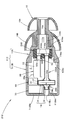
- FIG. 1 is a side sectional view showing an ear canal wearing type earphone microphone 10 according to an embodiment of the present invention.
- an ear canal-equipped earphone microphone 10 is housed in a housing 12 having a sound guide hole 12a formed in a front end portion (right end portion in FIG. 1), and the housing 12.
- the microphone unit 14 and the speaker unit 20 and the ear chip 16 attached to the front end portion of the housing 12 are provided.
- the ear canal-mounted earphone microphone 10 is used to collect body sounds such as heartbeats and pulse sounds while the eartip 16 is mounted on the ear canal.
- the housing 12 has a configuration in which a front member 12A and a rear member 12B are joined.
- the front member 12A and the rear member 12B are both made of a hard material such as aluminum or hard resin.
- the front member 12A is formed so that the diameter decreases toward the front, and a small-diameter cylindrical portion 12Ab protruding forward is formed at the center of the front end wall 12Aa.
- the sound guide hole 12a is formed in the small diameter cylindrical portion 12Ab, and the ear tip 16 is attached to the small diameter cylindrical portion 12Ab.
- the rear end surface 12Ac of the front member 12A is formed in an annular shape. Further, the inner peripheral surface 12Ad of the front member 12A is configured by a cylindrical surface whose diameter increases in two steps toward the rear.
- the rear member 12B is configured as a bottomed cylindrical member extending in the front-rear direction, and the rear end portion is configured as a rear end wall 12Bb.
- the front end surface 12Ba of the rear member 12B is sealed over the entire periphery by welding, adhesion, or the like in a state where the front end surface 12Ba is in contact with the outer peripheral edge portion of the rear end surface 12Ac of the front member 12A.
- a gasket 18 having a cylindrical outer peripheral surface is disposed at the front end of the internal space C of the housing 12.
- the gasket 18 is made of a soft material such as silicone resin or rubber.
- the gasket 18 is in a state in which the outer peripheral surface thereof is fitted into the small diameter portion of the inner peripheral surface 12Ad of the front member 12A from the rear side until the front end surface contacts the front end wall 12Aa of the front member 12A. Has been inserted.
- the gasket 18 has a front half formed in a cylindrical shape and a rear half formed in a columnar shape, and a first and second through-hole 18a extending in the front-rear direction with a circular cross-sectional shape at the center of the rear half. , 18b are formed at intervals in the vertical direction.
- the first and second through holes 18a and 18b allow the internal space C of the housing 12 to communicate with the sound guide hole 12a.
- the microphone unit 14 is arranged behind the speaker unit 20. Further, a signal processing circuit unit 60 is arranged alongside the microphone unit 14 on the rear side of the speaker unit 20 in the internal space C, and a battery 70 is arranged further on the rear side thereof.
- the signal processing circuit unit 60 has an antenna function, and is configured to be able to transmit / receive to / from an external device (not shown) such as a smartphone.
- the signal processing circuit unit 60 is supported by the rear member 12B.
- the battery 70 is configured to supply power to the microphone unit 14, the speaker unit 20, and the signal processing circuit unit 60.
- the battery 70 is supported by the rear member 12B.
- the speaker unit 20 is a balanced armature type speaker and has a structure in which a diaphragm and a drive unit (not shown) are accommodated in a housing 52.
- the housing 52 has a substantially rectangular parallelepiped outer shape that is long in the front-rear direction, and a sound emitting hole 52a is formed at the lower end portion of the front end surface thereof.
- a sound emission nozzle 54 formed so as to surround the sound emission hole 52a is attached to the front end portion of the housing 52 by welding or the like.
- a pair of terminal portions 20 a for electrically connecting the speaker unit 20 to the signal processing circuit unit 60 is disposed at the rear portion of the housing 52.
- the speaker unit 20 is positioned in a state where the tip of the sound emitting nozzle 54 is inserted into the second through hole 18b of the gasket 18 from the rear side.
- the speaker unit 20 generates a sound wave corresponding to the signal current from the signal processing circuit unit 60, and radiates the sound wave to the sound guide hole 12a through the sound output hole 52a and the second through hole 18b. It has become.
- the positioning of the speaker unit 20 may be performed only by inserting the tip of the sound emitting nozzle 54 into the second through hole 18b of the gasket 18, or the housing 52 and the inner peripheral surface of the rear member 12B.
- a spacer (not shown) may be disposed between them to support a plurality of locations in the circumferential direction.
- a first tubular member 28A extending in the front-rear direction is disposed below the speaker unit 20.
- the first cylindrical member 28A may be made of a hard material such as aluminum or hard resin, or may be made of a soft material such as silicone resin or rubber.
- the front end portion of the first cylindrical member 28A is inserted into the first through hole 18a of the gasket 18.
- the first cylindrical member 28 ⁇ / b> A is formed so as to extend rearward from the speaker unit 20.
- the microphone unit 14 includes a diaphragm 22 and a housing 24 configured to form a front space Cf and a back space Cr on both front and rear sides of the diaphragm 22.
- the housing 24 is formed with a first sound collection hole 24 a and a second sound collection hole 24 b that allow the front space Cf and the back space Cr to communicate with the external space of the housing 24.
- a first sound collecting nozzle 26A formed so as to surround the first sound collecting hole 24a is attached to the front surface of the housing 24 by welding or the like.
- a second sound collecting nozzle 26B formed so as to surround the second sound collecting hole 24b is attached to the rear surface of the housing 24 by welding or the like.
- the microphone unit 14 is disposed along a vertical plane perpendicular to the front-rear direction, and is connected to the rear end portion of the first cylindrical member 28A at the first sound collection nozzle 26A. This connection is performed by inserting the front end portion of the first sound collecting nozzle 26A into the rear end portion of the first cylindrical member 28A.
- a circular opening 12Bc is formed in the rear end wall 12Bb.
- the opening 12Bc is formed in a positional relationship that is concentric with the first through hole 18a formed in the gasket 18, and has the same cross-sectional shape as the first through hole 18a.
- a second cylindrical member 28 ⁇ / b> B extending in the front-rear direction is disposed behind the microphone unit 14 in the internal space C of the housing 12.
- the second cylindrical member 28B is made of the same material as the first cylindrical member 28A and has the same cross-sectional shape as the first cylindrical member 28A.
- the second cylindrical member 28B is connected to the second sound collection nozzle 26B of the microphone unit 14 at the front end thereof. This connection is performed by inserting the tip of the second sound collecting nozzle 26B into the front end of the second cylindrical member 28B.
- the rear end portion of the second cylindrical member 28B is inserted into the opening portion 12Bc of the rear end wall 12Bb.
- the front end portion of the first sound collecting nozzle 26A is inserted into the rear end portion of the first cylindrical member 28A and the first cylindrical shape.
- the front end portion of the member 28A is inserted into the first through hole 18a of the gasket 18, and the front end portion of the second sound collecting nozzle 26B is inserted into the front end portion of the second cylindrical member 28B, and the second cylindrical member 28B.
- the rear end portion may be simply inserted into the opening 12Bc of the rear end wall 12Bb, or a spacer (not shown) may be disposed between the housing 24 and the inner peripheral surface of the rear member 12B. You may make it carry out by adding the structure etc. which are supported in several places of the circumferential direction.
- the eartip 16 is made of a soft material such as silicone rubber.
- a through hole 16a that penetrates the ear tip 16 in the front-rear direction is formed.
- the through hole 16a communicates with the sound guide hole 12a in a state where the ear tip 16 is attached to the small diameter cylindrical portion 12Ab.
- the through hole 16a is formed with a smaller diameter than the sound guide hole 12a.
- the eartip 16 includes two front and rear flange portions 16A and 16B that spread in a substantially parabolic shape toward the rear side. At that time, the flange portion 16B on the rear side is formed with a larger diameter than the flange portion 16A on the front side.
- the two front and rear flange portions 16A and 16B are brought into close contact with the wall surface of the ear canal to form a sealed space in the ear canal by the ear canal wall, the eardrum and the ear tip 16. It has become.
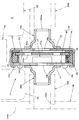
- FIG. 2 is a side sectional view showing the configuration of the microphone unit 14 in detail.
- the microphone unit 14 is a small electret condenser microphone having a circular outer shape of about ⁇ 5 to 10 mm and a thickness of about 1 to 3 mm when viewed from the front.
- the diaphragm 22 is housed in the housing 24 together with the support ring 32, the back electrode plate 34, the spacer 36, the conducting member 38, the insulating member 40, and the impedance conversion element 42.
- the housing 24 includes a conductive cover 44 and a circuit board 46.
- the conductive cover 44 is a cap-like member having a circular outer shape when viewed from the front, and is formed by pressing a metal plate.
- the circuit board 46 has a circular shape with an outer diameter slightly smaller than the inner diameter of the conductive cover 44 in a front view, and is arranged in parallel with the front wall of the conductive cover 44.
- An annular bent portion 44a extending so as to bend to the inner peripheral side is extended at the rear end portion of the peripheral wall of the conductive cover 44. The annular bent portion 44a is caulked and fixed to the circuit board 46. Yes.
- the first sound collection hole 24 a of the housing 24 is formed at the center of the front wall of the conductive cover 44.
- the second sound collection hole 24 b of the housing 24 is formed in the circuit board 46.
- Each of the first sound collection hole 24a and the second sound collection hole 24b has a circular shape, and the second sound collection hole 24b is formed with a smaller diameter than the first sound collection hole 24a.
- the first sound collection hole 24a and the second sound collection hole 24b can be configured by a plurality of small holes, respectively.
- a circular opening 26Aa is formed at the tip of the first sound collection nozzle 26A.
- the second sound collection nozzle 26B has the same configuration as the first sound collection nozzle 26A.
- the diaphragm 22 has a structure in which a metal vapor deposition film is formed on the front surface of the polymer film, and a micro hole 22a for adjusting the atmospheric pressure is formed at the center thereof.
- the diaphragm 22 is supported by the support ring 32 at the outer peripheral edge portion thereof.
- the support ring 32 is made of a thin metal plate and is formed in an annular shape.
- the diaphragm 22 is stretched and fixed to the rear surface of the support ring 32 (that is, fixed by adhesion or the like in a tensioned state).
- the back electrode plate 34 has a circular outer shape that is slightly smaller than the outer peripheral surface of the support ring 32 when viewed from the front, and is disposed close to the rear of the diaphragm 22.
- the back electrode plate 34 has a configuration in which an electret layer 34a is disposed on the front surface of an electrode plate body made of a metal plate.
- the electret layer 34a is generated by subjecting an insulating film formed on the front surface of the electrode plate body to a polarization treatment with a predetermined charge voltage, thereby applying a predetermined surface potential.
- the back electrode plate 34 is formed with through holes 34b penetrating the back electrode plate 34 in the front-rear direction at a plurality of locations in the circumferential direction.
- the spacer 36 is formed of a thin resin plate formed in an annular shape, and is disposed between the diaphragm 22 and the back electrode plate 34.
- the diaphragm 22 and the electret layer 34a of the back electrode plate 34 are arranged opposite to each other in parallel via the spacer 36, so that a capacitor portion is configured.
- the circuit board 46 is disposed behind the back electrode plate 34. Conductive layers (not shown) are formed in a predetermined pattern on both front and rear surfaces of the circuit board 46. On the rear surface of the circuit board 46, a pair of terminal portions 14a for electrically connecting the microphone unit 14 to the signal processing circuit unit 60 is formed.
- the impedance conversion element 42 is mounted on the front surface of the circuit board 46. At this time, the impedance conversion element 42 is disposed at a position deviating from the formation position of the second sound collection hole 24b.
- the conducting member 38 is a substantially cylindrical member, and is arranged between the circuit board 46 and the back electrode plate 34 so as to conduct between them.
- the insulating member 40 is an annular member and is arranged between the back electrode plate 34 and the conductive member 38 and the peripheral wall of the conductive cover 44 to insulate them.
- the conductive cover 44 is caulked and fixed to the circuit board 46 at the annular bent portion 44 a, and the conductive layer formed on the rear surfaces of the conductive cover 44 and the circuit board 46 by the caulking is fixed. It is designed to be connected to.
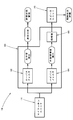
- FIG. 3 is a block diagram showing the configuration of the ear canal-mounted earphone microphone 10.
- the acoustic signal picked up by the microphone unit 14 (that is, the acoustic signal of the biological sound picked up from the first sound pickup hole 24a and the second sound pickup).
- the sound signal of the external environmental sound collected from the hole 24 b is input to the signal processing circuit unit 60.
- the signal processing circuit unit 60 includes a low-pass filter 62 and a high-pass filter 64 that are arranged in parallel, and an amplifier 66 that is connected to the high-pass filter 64.
- the acoustic signal input from the microphone unit 14 is passed through the low-pass filter 62 to detect a biological sound that is an acoustic signal in a low frequency band, and is passed through the high-pass filter 64 to generate a high frequency. An external environmental sound that is an acoustic signal in a band is detected.
- the acoustic signal of the body sound detected by the low-pass filter 62 is transmitted to an external device, and waveform analysis is performed in the external device, so that the analysis result is used for health condition management.
- the acoustic signal of the external environmental sound detected by the high-pass filter 64 is amplified by the amplifier 66 and then output to the speaker unit 20 and radiated as sound waves from the speaker unit 20 into the external auditory canal. It has come to be used for grasping.
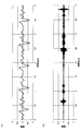
- FIG. 4 is a diagram showing a specific example of the waveform of the acoustic signal collected by the microphone unit 14.
- the waveform shown in FIG. 4A is the waveform of the low frequency band acoustic signal detected by the low pass filter 62.
- This waveform is a waveform of a biological sound (specifically, a heartbeat sound) collected from the first sound collection hole 24a, and is a periodic waveform of about 1 to 3 Hz.
- the waveform shown in FIG. 4B is the waveform of the high frequency band acoustic signal detected by the high pass filter 64.
- This waveform is a waveform of an external environmental sound (specifically speaking voice) collected from the second sound collection hole 24b, and is an irregular waveform.
- the ear canal-mounted earphone microphone 10 has a configuration in which a speaker unit 20 is disposed together with a microphone unit 14 in a housing 12.
- the microphone unit 14 communicates the first sound collecting hole 24a with the sound conducting hole 12a of the housing 12 and the second sound collecting hole 24b. Since it arrange
- the single microphone unit 14 it is possible to pick up a biological sound from the first sound pickup hole 24a and pick up an external environmental sound from the second sound pickup hole 24b. Therefore, there is no need to use two microphone units as in the prior art, and it is possible to prevent the casing 12 from becoming large.
- the ear canal-mounted earphone microphone 10 in the ear canal-mounted earphone microphone 10, it is possible to collect a body sound and an external environmental sound without increasing the size of the housing 12.
- the ear canal-mounted earphone microphone 10 with a function as a hearing aid or an external environmental sound monitor. Moreover, since the housing
- the body sound since the body sound is detected as an acoustic signal in a low frequency band, it can be detected by passing the acoustic signal collected by the microphone unit 14 through the low-pass filter 62, while the external environmental sound is detected. Since it is detected as an acoustic signal in a high frequency band, it can be detected by passing the acoustic signal collected by the microphone unit 14 through the high-pass filter 64.
- the cutoff frequency of each of the low-pass filter 62 and the high-pass filter 64 can be set as appropriate according to the usage environment of the ear canal-mounted earphone microphone 10.
- the ear canal-equipped earphone microphone 10 has a configuration in which the speaker unit 20 is disposed together with the microphone unit 14 in the housing 12, so that the user can enjoy music and the like output from the speaker unit 20.
- a living body sound can be collected by the microphone unit 14 while utilizing this.
- an amplifier 66 that amplifies an acoustic signal collected by the microphone unit 14 from the second sound collection hole 24b and outputs the amplified sound signal to the speaker unit 20 is disposed in the housing 12.
- the type earphone microphone 10 can be made more suitable for a hearing aid or an external environmental sound monitor.
- the microphone unit 14 since the microphone unit 14 is arranged behind the speaker unit 20, the microphone unit 14 and the speaker unit 20 are arranged in parallel as in the conventional case.
- the outer diameter of the housing 12 can be reduced without reducing the size of the microphone unit 14.
- the sensitivity reduction of the microphone unit 14 can be prevented and the sound collection performance of the body sound and the external environmental sound can be maintained.
- the gasket 18 is disposed at the front end portion in the housing 12, and the first and second through holes 18a that allow the gasket 18 to communicate the internal space C of the housing 12 with the sound guide hole 12a.
- 18b, and a first sound collection nozzle 26A formed so as to surround the first sound collection hole 24a is attached to the housing 24 of the microphone unit 14, and this first sound collection
- the rear end portion of the first cylindrical member 28A extending in the front-rear direction is connected to the nozzle 26A, and the front end portion of the first cylindrical member 28A is inserted into the first through hole 18a.
- the sound emitting nozzle 54 formed so as to surround the sound emitting hole 52a is attached to this, and the sound emitting nozzle 54 is inserted into the second through hole 18b. It is possible to obtain the results.
- the gasket 18, the first sound collection nozzle 26A, and the first cylindrical member 28A can reliably communicate the first sound collection hole 24a of the microphone unit 14 with the sound guide hole 12a.
- the sound nozzle 54 can reliably connect the sound emission hole 52a of the speaker unit 20 to the sound guide hole 12a.
- the front end portion of the first cylindrical member 28A is inserted into the first through hole 18a and the rear end portion thereof is connected to the first sound collecting nozzle 26A, so that the interior of the first cylindrical member 28A is increased.
- the space can be made to function as a component of a low-pass filter for making it difficult for an acoustic signal output from the speaker unit 20 to reach the first sound collection hole 24a of the microphone unit 14, thereby collecting sound with respect to biological sound. Can be increased. At that time, it is possible to easily finely adjust the sound pressure sensitivity by appropriately adjusting the length and the inner diameter of the first cylindrical member 28A.
- a space having a large capacity which is the internal space of the sound guide hole 12a of the housing 12 and the gasket 18, is formed between the first cylindrical member 28A and the second through hole 18b. Can enhance the function.
- a second sound collecting nozzle 26B formed so as to surround the second sound collecting hole 24b is attached to the housing 24 of the microphone unit 14, and extends in the front-rear direction to the second sound collecting nozzle 26B. Since the front end portion of the second cylindrical member 28B is connected and the rear end portion of the second cylindrical member 28B is inserted into the opening 12Bc of the housing 12, the following operational effects can be obtained. Can do.
- the second sound collecting nozzle 26B and the second cylindrical member 28B can reliably communicate the second sound collecting hole 24b of the microphone unit 14 and the opening 12Bc of the housing 12. As a result, it is possible to easily collect external environmental sound without affecting the sound collecting function of the body sound from the first sound collecting hole 24a of the microphone unit 14.
- the microphone unit 14 has been described as being disposed along a vertical plane orthogonal to the front-rear direction. However, the microphone unit 14 is disposed along a plane inclined with respect to the vertical plane orthogonal to the front-rear direction. It is also possible.
- the microphone unit 14 is an electret condenser microphone
- other microphones for example, an electrodynamic microphone in which a sound collecting hole is formed in the back space of the diaphragm
- the speaker unit 20 is a balanced armature type speaker
- other speakers for example, an electrodynamic speaker
- the front end portion of the second cylindrical member 28B is connected to the second sound collecting nozzle 26B of the microphone unit 14 and the rear end portion is inserted into the opening portion 12Bc of the housing 12.
- the signal processing circuit unit 60 having the antenna function and the battery 70 are housed in the housing 12.
- the signal is transmitted from the housing 12 via the cable drawn to the outside. It is also possible to employ a configuration in which the processing circuit unit 60 is connected to an external device or a power source.
- FIG. 5 is a view similar to FIG. 1, showing an ear canal-mounted earphone microphone 110 according to this modification.
- the basic configuration of the earphone microphone 110 attached to the ear canal is the same as that of the above embodiment, but does not include the second cylindrical member 28B as in the above embodiment, and The configuration of the rear member 112B of the housing 112 is different from that of the above embodiment.
- the housing 112 of this modification also has a sound conducting hole 112a similar to the sound conducting hole 12a of the housing 12 of the above embodiment, and a circular opening is formed in the rear end wall 112Bb of the rear member 112B. 112Bc is formed. The opening 112Bc is formed in a positional relationship that is concentric with the first through hole 18a formed in the gasket 18.
- this rear member 112B is formed with a cylindrical portion 112Bd extending forward from the opening 112Bc.
- the inner diameter of the cylindrical portion 112Bd is set to the same value as the inner diameter of the first cylindrical member 28A.
- the 2nd sound collection nozzle 26B of the microphone unit 14 is connected with the front-end part of this cylindrical part 112Bd. This connection is performed by inserting the tip of the second sound collecting nozzle 26B into the front end of the cylindrical portion 112Bd.
- the number of parts of the ear canal-mounted earphone microphone 110 can be reduced, and the microphone unit 14 can be supported more reliably.
- FIG. 6 is a view similar to FIG. 1, showing an ear canal-mounted earphone microphone 210 according to this modification.
- the basic configuration of the ear canal-mounted earphone microphone 210 is the same as that of the first modified example, but includes the first tubular member 28A as in the first modified example. Further, the configurations of the first sound collecting nozzle 226A and the gasket 218 are different from those of the first modified example.
- the diameter of the first through hole 218a is set to a value smaller than the diameter of the first through hole 18a of the gasket 18 of the first modification.
- first sound collecting nozzle 226A of the present modification extends longer in a cylindrical shape toward the front than the first sound collecting nozzle 26A of the first modification, and the tip thereof is the first of the gasket 218.
- the first through hole 218a is inserted from the rear side.
- the configuration of the gasket 218 is the same as that of the gasket 18 of the first modification with respect to the portion other than the first through hole 218a, and the second penetration is the same as the second through hole 18b of the first modification. It has a hole 218b.
- the number of parts of the ear canal-mounted earphone microphone 210 can be further reduced, and the microphone unit 14 can be supported more reliably.
- the second sound collection nozzle 26B also has a configuration that extends longer in the tubular shape toward the rear than the second sound collection nozzle 26B of the first modification, and the rear A configuration in which the cylindrical portion 112Bd of the member 112B is formed in a short length, and the front end portion of the second sound collecting nozzle 26B is inserted into the front end portion of the cylindrical portion 112Bd, or the cylindrical portion 112Bd is It can be abolished, and the tip of the second sound collecting nozzle 26B can be directly inserted into the opening 112Bc.
Landscapes
- Health & Medical Sciences (AREA)
- Engineering & Computer Science (AREA)
- Life Sciences & Earth Sciences (AREA)
- Physics & Mathematics (AREA)
- Signal Processing (AREA)
- Acoustics & Sound (AREA)
- Cardiology (AREA)
- Otolaryngology (AREA)
- General Health & Medical Sciences (AREA)
- Heart & Thoracic Surgery (AREA)
- Molecular Biology (AREA)
- Physiology (AREA)
- Veterinary Medicine (AREA)
- Biophysics (AREA)
- Pathology (AREA)
- Biomedical Technology (AREA)
- Public Health (AREA)
- Medical Informatics (AREA)
- Vascular Medicine (AREA)
- Surgery (AREA)
- Animal Behavior & Ethology (AREA)
- Neurosurgery (AREA)
- Ophthalmology & Optometry (AREA)
- Headphones And Earphones (AREA)
- Measuring Pulse, Heart Rate, Blood Pressure Or Blood Flow (AREA)
- Obtaining Desirable Characteristics In Audible-Bandwidth Transducers (AREA)
Abstract
L'invention concerne un microphone à écouteur placé dans le conduit auditif externe, qui peut collecter un son biologique et un son de l'environnement extérieur sans avoir besoin d'un boîtier plus grand. Selon la configuration adoptée, une unité haut-parleur (20) est disposée avec une unité microphone (14) dans un boîtier (12). Dans cette configuration, une ouverture (12Bc) destinée à la communication de l'espace interne (C) du boîtier (12) avec l'espace externe de ce dernier est pratiquée dans l'extrémité arrière du boîtier (12). L'unité microphone (14) est conçue de manière à posséder des premier et second trous de recueil de sons (24a, 24b), et le premier trou de recueil de sons (24a) est amené à communiquer avec un trou de guidage de sons (12a) du boîtier (12) tandis que le second trou de recueil de sons (24b) est amené à communiquer avec l'ouverture (12Bc) du boîtier (12). Ainsi, il est possible de collecter un son biologique au moyen du premier trou de recueil de sons (24a) et de recueillir un son de l'environnement extérieur au moyen du second trou de recueil de sons (24b) dans une seule unité microphone (14), ce qui évite d'avoir à utiliser deux unités microphones comme par le passé.
Applications Claiming Priority (2)
| Application Number | Priority Date | Filing Date | Title |
|---|---|---|---|
| JP2014261169A JP6478317B2 (ja) | 2014-12-24 | 2014-12-24 | 外耳道装着型イヤホンマイク |
| JP2014-261169 | 2014-12-24 |
Publications (1)
| Publication Number | Publication Date |
|---|---|
| WO2016103779A1 true WO2016103779A1 (fr) | 2016-06-30 |
Family
ID=56149823
Family Applications (1)
| Application Number | Title | Priority Date | Filing Date |
|---|---|---|---|
| PCT/JP2015/072816 Ceased WO2016103779A1 (fr) | 2014-12-24 | 2015-08-12 | Microphone à écouteur placé dans le conduit auditif externe |
Country Status (2)
| Country | Link |
|---|---|
| JP (1) | JP6478317B2 (fr) |
| WO (1) | WO2016103779A1 (fr) |
Cited By (3)
| Publication number | Priority date | Publication date | Assignee | Title |
|---|---|---|---|---|
| WO2019010864A1 (fr) * | 2017-07-13 | 2019-01-17 | 江阴思安塑胶防护科技有限公司 | Filtre de bruit et bouchon d'oreille comprenant celui-ci |
| WO2020117008A1 (fr) | 2018-12-07 | 2020-06-11 | Samsung Electronics Co., Ltd. | Dispositif électronique comprenant un haut-parleur et un microphone |
| WO2023125727A1 (fr) * | 2021-12-31 | 2023-07-06 | 华为技术有限公司 | Écouteur, gabarit d'assemblage et procédé de fabrication d'écouteur |
Families Citing this family (3)
| Publication number | Priority date | Publication date | Assignee | Title |
|---|---|---|---|---|
| WO2019187610A1 (fr) * | 2018-03-26 | 2019-10-03 | ソニー株式会社 | Dispositif de sortie acoustique |
| KR102860000B1 (ko) | 2020-07-17 | 2025-09-15 | 삼성전자주식회사 | 웨어러블 장치 |
| WO2022024162A1 (fr) * | 2020-07-25 | 2022-02-03 | 株式会社メイ | Écouteur |
Citations (11)
| Publication number | Priority date | Publication date | Assignee | Title |
|---|---|---|---|---|
| JPH03505639A (ja) * | 1988-06-24 | 1991-12-05 | センサー・エレクトロニクス・インコーポレイテッド | アクティブ雑音減少システム |
| JPH0485900U (fr) * | 1990-11-29 | 1992-07-27 | ||
| JPH0591585A (ja) * | 1991-09-30 | 1993-04-09 | Nitsuko Corp | ヘツドホン |
| WO2005094118A1 (fr) * | 2004-03-25 | 2005-10-06 | Nap Enterprise Co., Ltd. | Système suppresseur d'écho d'oscillation |
| JP2005286500A (ja) * | 2004-03-29 | 2005-10-13 | Yashima Denki Kk | 補聴器用マイク付きイヤホン |
| JP2007281711A (ja) * | 2006-04-04 | 2007-10-25 | Kenwood Corp | イヤーモールド型送受話器及び無線通信装置 |
| WO2008139931A1 (fr) * | 2007-05-09 | 2008-11-20 | Nap Enterprise Co., Ltd. | Microphone d'écouteur |
| JP2010147982A (ja) * | 2008-12-22 | 2010-07-01 | Hosiden Corp | リモコン付きステレオイヤホンマイク |
| WO2013147385A1 (fr) * | 2012-03-29 | 2013-10-03 | Shin Doo Sik | Boîtier insonorisé pour écouteur et écouteur câblé et sans fil le comprenant |
| JP2014155145A (ja) * | 2013-02-13 | 2014-08-25 | Funai Electric Co Ltd | イヤホンマイク |
| JP2014187679A (ja) * | 2013-02-20 | 2014-10-02 | Funai Electric Co Ltd | イヤホンマイク |
Family Cites Families (2)
| Publication number | Priority date | Publication date | Assignee | Title |
|---|---|---|---|---|
| DE3815445A1 (de) * | 1988-05-06 | 1989-11-16 | Kuesters Eduard Maschf | Verfahren zur verminderung von schwingungen an aufeinanderfolgenden walzenpaaren und solche walzenpaare aufweisende vorrichtung |
| JP2015061115A (ja) * | 2013-09-17 | 2015-03-30 | 船井電機株式会社 | 音声入出力装置 |
-
2014
- 2014-12-24 JP JP2014261169A patent/JP6478317B2/ja active Active
-
2015
- 2015-08-12 WO PCT/JP2015/072816 patent/WO2016103779A1/fr not_active Ceased
Patent Citations (11)
| Publication number | Priority date | Publication date | Assignee | Title |
|---|---|---|---|---|
| JPH03505639A (ja) * | 1988-06-24 | 1991-12-05 | センサー・エレクトロニクス・インコーポレイテッド | アクティブ雑音減少システム |
| JPH0485900U (fr) * | 1990-11-29 | 1992-07-27 | ||
| JPH0591585A (ja) * | 1991-09-30 | 1993-04-09 | Nitsuko Corp | ヘツドホン |
| WO2005094118A1 (fr) * | 2004-03-25 | 2005-10-06 | Nap Enterprise Co., Ltd. | Système suppresseur d'écho d'oscillation |
| JP2005286500A (ja) * | 2004-03-29 | 2005-10-13 | Yashima Denki Kk | 補聴器用マイク付きイヤホン |
| JP2007281711A (ja) * | 2006-04-04 | 2007-10-25 | Kenwood Corp | イヤーモールド型送受話器及び無線通信装置 |
| WO2008139931A1 (fr) * | 2007-05-09 | 2008-11-20 | Nap Enterprise Co., Ltd. | Microphone d'écouteur |
| JP2010147982A (ja) * | 2008-12-22 | 2010-07-01 | Hosiden Corp | リモコン付きステレオイヤホンマイク |
| WO2013147385A1 (fr) * | 2012-03-29 | 2013-10-03 | Shin Doo Sik | Boîtier insonorisé pour écouteur et écouteur câblé et sans fil le comprenant |
| JP2014155145A (ja) * | 2013-02-13 | 2014-08-25 | Funai Electric Co Ltd | イヤホンマイク |
| JP2014187679A (ja) * | 2013-02-20 | 2014-10-02 | Funai Electric Co Ltd | イヤホンマイク |
Cited By (7)
| Publication number | Priority date | Publication date | Assignee | Title |
|---|---|---|---|---|
| WO2019010864A1 (fr) * | 2017-07-13 | 2019-01-17 | 江阴思安塑胶防护科技有限公司 | Filtre de bruit et bouchon d'oreille comprenant celui-ci |
| WO2020117008A1 (fr) | 2018-12-07 | 2020-06-11 | Samsung Electronics Co., Ltd. | Dispositif électronique comprenant un haut-parleur et un microphone |
| US11076215B2 (en) | 2018-12-07 | 2021-07-27 | Samsung Electronics Co., Ltd. | Electronic device including speaker and microphone |
| CN113228703A (zh) * | 2018-12-07 | 2021-08-06 | 三星电子株式会社 | 包括扬声器和麦克风的电子装置 |
| EP3864857A4 (fr) * | 2018-12-07 | 2021-12-22 | Samsung Electronics Co., Ltd. | Dispositif électronique comprenant un haut-parleur et un microphone |
| CN113228703B (zh) * | 2018-12-07 | 2024-05-07 | 三星电子株式会社 | 包括扬声器和麦克风的电子装置 |
| WO2023125727A1 (fr) * | 2021-12-31 | 2023-07-06 | 华为技术有限公司 | Écouteur, gabarit d'assemblage et procédé de fabrication d'écouteur |
Also Published As
| Publication number | Publication date |
|---|---|
| JP6478317B2 (ja) | 2019-03-06 |
| JP2016122915A (ja) | 2016-07-07 |
Similar Documents
| Publication | Publication Date | Title |
|---|---|---|
| JP6478317B2 (ja) | 外耳道装着型イヤホンマイク | |
| CN109511043B (zh) | 一种骨传导扬声器以及骨传导发声装置 | |
| US10123137B2 (en) | Wearable acoustic device with microphone | |
| JP6100730B2 (ja) | イヤホン | |
| JP5606194B2 (ja) | 狭指向性コンデンサマイクロホン | |
| US9219953B2 (en) | Earphone microphone | |
| US9872113B2 (en) | Measurement device and measurement system | |
| JP6348931B2 (ja) | インイヤーヘッドセットモジュール | |
| US11540043B1 (en) | Active noise reduction earbud | |
| US20100208927A1 (en) | Microphone module for a hearing device | |
| WO2017090311A1 (fr) | Dispositif de collecte de son | |
| WO2020161982A1 (fr) | Dispositif acoustique | |
| WO2016098382A1 (fr) | Microphone d'écouteur de type posé en dehors du canal auditif | |
| JP6676258B2 (ja) | 生体音測定システムにおける測定データの校正方法 | |
| WO2015033970A1 (fr) | Haut-parleur d'assistance aux personnes présentant une déficience auditive | |
| JP6250582B2 (ja) | 難聴者支援スピーカ | |
| US8855350B2 (en) | Patterned implantable electret microphone | |
| JP2016201706A (ja) | 連通管付きイヤホン | |
| CN215678914U (zh) | 一种智能眼镜 | |
| US8755551B2 (en) | Hearing apparatus having a special sound channel | |
| US10129638B2 (en) | Microphone for a hearing aid | |
| WO2016098381A1 (fr) | Microphone de type posé en dehors du canal auditif | |
| TW201515474A (zh) | 收音裝置及其製造方法 | |
| EP4607960A1 (fr) | Dôme d'étanchéité amélioré pour prothèse auditive, et prothèse auditive dotée d'un dôme d'étanchéité amélioré | |
| EP4198975A1 (fr) | Dispositif électronique et procédé permettant d'obtenir la parole d'un utilisateur dans un premier signal sonore |
Legal Events
| Date | Code | Title | Description |
|---|---|---|---|
| 121 | Ep: the epo has been informed by wipo that ep was designated in this application |
Ref document number: 15872348 Country of ref document: EP Kind code of ref document: A1 |
|
| NENP | Non-entry into the national phase |
Ref country code: DE |
|
| 122 | Ep: pct application non-entry in european phase |
Ref document number: 15872348 Country of ref document: EP Kind code of ref document: A1 |