WO2016104681A1 - Dispositif de direction à assistance électrique - Google Patents
Dispositif de direction à assistance électrique Download PDFInfo
- Publication number
- WO2016104681A1 WO2016104681A1 PCT/JP2015/086182 JP2015086182W WO2016104681A1 WO 2016104681 A1 WO2016104681 A1 WO 2016104681A1 JP 2015086182 W JP2015086182 W JP 2015086182W WO 2016104681 A1 WO2016104681 A1 WO 2016104681A1
- Authority
- WO
- WIPO (PCT)
- Prior art keywords
- offset
- current command
- motor
- command value
- electric power
- Prior art date
- Legal status (The legal status is an assumption and is not a legal conclusion. Google has not performed a legal analysis and makes no representation as to the accuracy of the status listed.)
- Ceased
Links
Images


Classifications
-
- B—PERFORMING OPERATIONS; TRANSPORTING
- B62—LAND VEHICLES FOR TRAVELLING OTHERWISE THAN ON RAILS
- B62D—MOTOR VEHICLES; TRAILERS
- B62D5/00—Power-assisted or power-driven steering
- B62D5/04—Power-assisted or power-driven steering electrical, e.g. using an electric servo-motor connected to, or forming part of, the steering gear
- B62D5/0457—Power-assisted or power-driven steering electrical, e.g. using an electric servo-motor connected to, or forming part of, the steering gear characterised by control features of the drive means as such
- B62D5/046—Controlling the motor
- B62D5/0463—Controlling the motor calculating assisting torque from the motor based on driver input
-
- B—PERFORMING OPERATIONS; TRANSPORTING
- B62—LAND VEHICLES FOR TRAVELLING OTHERWISE THAN ON RAILS
- B62D—MOTOR VEHICLES; TRAILERS
- B62D5/00—Power-assisted or power-driven steering
- B62D5/04—Power-assisted or power-driven steering electrical, e.g. using an electric servo-motor connected to, or forming part of, the steering gear
- B62D5/0457—Power-assisted or power-driven steering electrical, e.g. using an electric servo-motor connected to, or forming part of, the steering gear characterised by control features of the drive means as such
- B62D5/046—Controlling the motor
- B62D5/0466—Controlling the motor for returning the steering wheel to neutral position
-
- H—ELECTRICITY
- H02—GENERATION; CONVERSION OR DISTRIBUTION OF ELECTRIC POWER
- H02P—CONTROL OR REGULATION OF ELECTRIC MOTORS, ELECTRIC GENERATORS OR DYNAMO-ELECTRIC CONVERTERS; CONTROLLING TRANSFORMERS, REACTORS OR CHOKE COILS
- H02P25/00—Arrangements or methods for the control of AC motors characterised by the kind of AC motor or by structural details
- H02P25/16—Arrangements or methods for the control of AC motors characterised by the kind of AC motor or by structural details characterised by the circuit arrangement or by the kind of wiring
- H02P25/22—Multiple windings; Windings for more than three phases
-
- B—PERFORMING OPERATIONS; TRANSPORTING
- B62—LAND VEHICLES FOR TRAVELLING OTHERWISE THAN ON RAILS
- B62D—MOTOR VEHICLES; TRAILERS
- B62D5/00—Power-assisted or power-driven steering
- B62D5/04—Power-assisted or power-driven steering electrical, e.g. using an electric servo-motor connected to, or forming part of, the steering gear
- B62D5/0403—Power-assisted or power-driven steering electrical, e.g. using an electric servo-motor connected to, or forming part of, the steering gear characterised by constructional features, e.g. common housing for motor and gear box
Definitions
- the present invention relates to an electric power steering device that drives and controls a motor via an inverter based on a current command value serving as a steering command, and applies an assist force to the steering system of the vehicle by the motor.
- a two-system motor), and an inverter is provided for each system winding of the motor to form a multi-system (at least two systems) drive system, and a current command for steering torque for each multi-system drive system.
- the present invention relates to an electric power steering apparatus in which value characteristics are given so as to be unbalanced during left and right steering, and each drive system performs assist control according to separate current command value characteristics.
- one of the two-system motors is used for left steering and the other is used for right steering, eliminating the dead zone and eliminating the uncontrollable area.
- an electric power steering device as a device equipped with a motor control device for controlling a motor.
- the electric power steering device applies a steering assist force (assist force) to the steering mechanism of a vehicle by the rotational force of the motor.
- the driving force of the motor controlled by the electric power supplied from the inverter is applied to the steering shaft or the rack shaft by a transmission mechanism such as a gear.
- Such a conventional electric power steering apparatus performs feedback control of the motor current in order to accurately generate the torque of the steering assist force.
- the motor applied voltage is adjusted so that the difference between the current command value and the motor current detection value becomes small.
- the adjustment of the motor applied voltage is performed by the duty of PWM (pulse width modulation) control.
- PWM pulse width modulation
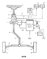
- a column shaft (steering shaft, handle shaft) 2 of a handle 1 is a reduction gear 3, universal joints 4a and 4b, a pinion rack mechanism 5, a tie rod 6a, 6b is further connected to the steering wheels 8L and 8R via hub units 7a and 7b. Further, the column shaft 2 is provided with a torque sensor 10 for detecting the steering torque Ts of the handle 1 and a rudder angle sensor 14 for detecting the steering angle ⁇ , and a motor 20 for assisting the steering force of the handle 1 is a reduction gear. 3 is connected to the column shaft 2 through 3.
- the control unit (ECU) 30 that controls the electric power steering apparatus is supplied with electric power from the battery 13 and also receives an ignition key (IG) signal via the ignition key 11.
- the control unit 30 calculates a current command value for assist (steering assist) control based on the steering torque Ts detected by the torque sensor 10 and the vehicle speed Vs detected by the vehicle speed sensor 12, and compensates the current command value.
- the current supplied to the EPS motor 20 is controlled by the voltage control command value Vref subjected to.
- the steering angle sensor 14 is not essential and may not be provided, and the steering angle can be obtained from a rotation sensor such as a resolver connected to the motor 20.
- the control unit 30 is connected to a CAN (Controller Area Network) 40 that exchanges various vehicle information, and the vehicle speed Vs can be received from the CAN 40.
- the control unit 30 can be connected to a non-CAN 41 that exchanges communications, analog / digital signals, radio waves, and the like other than the CAN 40.
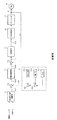
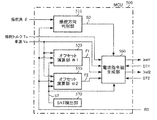
- the control unit 30 is mainly composed of an MCU (including a CPU, MPU, etc.), and FIG. 2 shows general functions executed by a program inside the MCU.
- the function and operation of the control unit 30 will be described with reference to FIG. 2.
- the steering torque Ts detected by the torque sensor 10 and the vehicle speed Vs detected by the vehicle speed sensor 12 (or from the CAN 40) are represented by the current command value Iref1.
- the current command value calculation unit 31 to be calculated is input.
- the current command value calculation unit 31 calculates a current command value Iref1, which is a control target value of the current supplied to the motor 20, using an assist map or the like based on the input steering torque Ts and vehicle speed Vs.
- the current command value Iref1 is input to the current limiter 33 through the adder 32A, and the current command value Irefm whose maximum current is limited is input to the subtractor 32B, and the deviation I (Irefm) from the fed back motor current value Im. -Im) is calculated, and the deviation I is input to the PI control unit 35 for improving the characteristics of the steering operation.
- the voltage control command value Vref whose characteristics are improved by the PI control unit 35 is input to the PWM control unit 36, and the motor 20 is PWM driven via an inverter 37 as a drive unit.
- the current value Im of the motor 20 is detected by the motor current detector 38 and fed back to the subtraction unit 32B.
- the inverter 37 uses a FET as a drive element, and is configured by a bridge circuit of the FET.
- a compensation signal CM from the compensation signal generator 34 is added to the adder 32A, and the compensation of the steering system system is performed by adding the compensation signal CM to improve the convergence and inertia characteristics.
- Compensation signal generation unit 34 adds self-aligning torque (SAT) 34-3 and inertia 34-2 by addition unit 34-4, and further adds convergence 34-1 to the addition result by addition unit 34-5.
- the addition result of the adder 34-5 is used as the compensation signal CM.
- Patent Document 1 an electric power steering device that improves the driver's steering feeling is disclosed in, for example, Japanese Patent Application Laid-Open No. 2007-237839 (Patent Document 1).
- an actuator capable of adjusting the steering torque is provided, a target steering angle is calculated based on the steering torque, and the output torque of the actuator is controlled so that the actual steering angle matches the target steering angle. Yes.
- the target steering angle is set to a constant value or a substantially constant value until a predetermined steering torque change occurs.
- Patent Document 1 has an essential problem that there is an element that becomes a dead zone that exists in an electric system, and the device itself cannot be controlled. In addition, in the vicinity that deviates from the dead zone (region that changes from the dead zone to the controllable region), it becomes discontinuous (inflection point), which may cause driver discomfort.
- Patent Document 2 a plurality of connection motors and a plurality of driving devices are shown, but the fifth harmonic component and the seventh harmonic component are shown.
- the target is not intended for control near the handle center, and cannot meet the above requirements.
- the present invention has been made under the circumstances as described above, and an object of the present invention is to provide unbalanced current command value characteristics with respect to steering torque for each of the multiple drive systems constituting the redundant system during left and right steering.
- Each drive system performs assist control according to a separate current command value characteristic, or eliminates an element that becomes a dead zone, and controls so that it becomes unbalanced at the time of left and right steering.
- the present invention relates to an electric power steering device that drives and controls a motor via an inverter based on a current command value serving as a steering command, and applies an assisting force to a steering system of the vehicle by the motor.
- the motor is a multi-system motor, and includes a multi-system drive system having the inverter for each system winding of the motor.
- the multi-system drive system has a multi-system current command value characteristic with respect to steering torque. This is achieved by giving an imbalance when steering left and right, and the multi-system drive system performing assist control according to different current command value characteristics.
- the object of the present invention is that the multi-system current command value characteristic has an offset near the steering wheel center, and the difference in the offset amount increases as the absolute value of the steering torque increases, or
- the degree of the offset is variable, or the variable is a vehicle speed sensitivity characteristic, or the vehicle speed sensitivity characteristic is such that the offset near the handle center decreases as the vehicle speed increases, and the difference in the offset amount
- the degree is large or small, or when the multi-system motor, the multi-system drive system, and the multi-system current command value characteristics are all at least two systems, or the motor is connected in a star connection 2 Due to the system winding, or the motor is a two-system winding of delta connection
- the multi-system motor, the multi-system drive system, and the multi-system current command value characteristic are all two systems, and a part of the two-system motor is used in the one-direction region by the one-direction current command value.
- the one-way current command value has an offset 1 by using the other part of the two-system motor in the other direction region by the other-direction current command value or in the vicinity of the handle center.
- the one-way current command value increases as the steering torque increases in the one-direction region because the other-direction current command value has an offset 2, or in the one-way region.
- the current command value for the other direction increases, or changes in the current command value for the one direction and the current command value for the other direction
- the offset 1 and the offset 2 are equal, or the offset 1 and the offset 2 are different from each other, or the offset 1 and the offset 2 change according to the vehicle speed. This is achieved more effectively.
- the present invention also relates to an electric power steering apparatus that controls driving of a motor via an inverter based on a current command value serving as a steering command, and applies assist force to a steering mechanism of the vehicle by the motor.
- the motor is at least a two-system motor
- the inverter is provided for each system winding of the motor
- a part of the at least two-system motor is used in a one-way region by a one-way current command value.
- the other part of the at least two-system motor is used for the other direction region by the other direction current command value
- the one direction current command value has an offset 1 near the handle center
- the other direction current command value is The offset 1 and the front of the vehicle based on the running state of the vehicle and the acting force applied to the steering mechanism. Is achieved by an offset 2 is calculated.
- the object of the present invention is that the one-way region is obtained when the offset 1 and the offset 2 change according to the acting force when the vehicle is in a straight traveling state, or in the straight traveling state. Then, the offset 1 increases as the acting force increases, and the offset 2 increases as the acting force increases in the other direction region, or in the straight traveling state, the action occurs in the one direction region.
- the offset 2 decreases as the force increases, and the offset 1 decreases as the acting force increases in the other direction region, or when the vehicle leaves the straight traveling state.
- the offset 2 is initially determined by the rotation angle of the steering mechanism and the acting force.
- the offset 1 and the offset 2 are gradually changed by returning to the values, and the characteristics of changing the current command value for one direction and the current command value for the other direction are changed by gradually returning to the initial value. Can be changed more effectively, or by the fact that the acting force is a self-aligning torque or a steering torque.
- the multi-system current command value characteristic for manual input is given to the multi-system drive system constituting the redundant system so as to be unbalanced at the time of left and right steering, Since the multi-system drive system performs assist control according to different current command value characteristics, there is no dead zone and discontinuity (inflection point), and the driver does not feel uncomfortable. In addition, since there is no dead zone near the handle center of the electrical system and the current command value for left and right steering is calculated and controlled separately so that the right steering and the left steering are unbalanced, it is discontinuous (variable). The extreme points are also gone.
- ⁇ Assist control is performed using multi-system current command value characteristics with respect to steering torque, so there is no uncontrollable area.
- the present invention is an electric power steering device that drives and controls a motor via an inverter (or GDM) based on a current command value serving as a steering command, and applies assist force to the steering system of the vehicle by the motor.
- the present invention eliminates the dead zone of an electrical system that has been a problem in the past and provides an electric power steering device that constitutes a redundant system.
- the motor is a multi-system motor (at least two-system motor), and an inverter is provided for each motor system winding to configure a multi-system (at least two systems) drive system.
- the current command value characteristic with respect to the steering torque is given so as to be unbalanced at the time of left and right steering, and each drive system performs assist control according to the separate current command value characteristic.
- Each current command value characteristic has an offset in the vicinity of zero of manual input (steering torque), that is, near the steering wheel center, and is a characteristic that increases in a curve as the absolute value of the steering torque increases.
- the flat characteristics, offset, degree of curve, etc. can be tuned and may be sensitive to vehicle speed.
- each current command value does not have a dead zone and discontinuous (inflection point) output characteristics, the driver feels uncomfortable and the steering feeling can be improved.
- the motor is multi-system connected (at least two system windings), and each system winding is driven and controlled separately, there is a great advantage in terms of space saving.
- the steering feeling is further improved.
- the vehicle driving state is determined, and the offsets F1 and F2 are determined based on the determination result of the driving state and the applied force (self-aligning torque (SAT), steering torque, column shaft reaction force, etc.) applied to the steering mechanism. Adjustments are made to assist the lateral flow, reducing the driver's burden.
- SAT self-aligning torque
- steering torque steering torque
- column shaft reaction force etc.
- a rack assist type or a pinion assist type may be used, and each may also be applied with a steering angle variable device. Is possible.
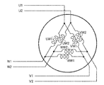
- FIG. 4 shows a star-connected three-phase motor.
- One system is composed of a U-phase winding UW1, a V-phase winding VW1, and a W-phase winding WW1, and the other one is a U-phase winding UW2, V It consists of a phase winding VW2 and a W-phase winding WW2.
- the motor is driven by passing a three-phase current through the windings UW1 to WW1 or the windings UW2 to WW2.
- FIG. 5 shows a delta-connected three-phase motor.
- One system is composed of a U-phase winding UW1, a V-phase winding VW1, and a W-phase winding WW1, and the other one is a U-phase winding UW2.
- the motor is driven by passing a three-phase current through the windings UW1 to WW1 or the windings UW2 to WW2.
- the motor used in the present invention may be a star connection or a delta connection.
- two drive systems for individually controlling the drive of each of the two-system motors are provided, and one of the systems (first system) is, for example, a current command shown in FIG.
- the current command value Iref1 based on the value characteristic IC1 is controlled to be unbalanced at the time of left and right steering, and the other system (second system) is controlled at the current command value Iref2 based on the current command value characteristic IC2 of FIG. To control unbalanced.
- the current command value characteristic IC1 is in the region of the right steering of manual input (steering torque) is positive direction, substantially planar positive offset to the predetermined value T 1 has F1, from manual input (steering torque) exceeds a predetermined value T 1, curvilinearly increases with increases in the region of the left steering to manual input (steering torque) becomes negative, a predetermined value - an offset F1 substantially planar forward to T 4, manual input (steering torque) is increased after exceeding the predetermined value -T 4, the curve a negative direction in accordance with increases in the negative direction, the left and right steering It is an unbalanced characteristic.
- the decrease characteristic in the negative direction may vary depending on the vehicle speed sensitivity, or may vary depending on tuning.
- the current command value characteristic IC2 is in the region of the right steering of manual input (steering torque) is positive direction, has an offset F2 substantially planar negative to a predetermined value T 2, manual input (steering torque) after exceeding a predetermined value T 2, curvilinearly increases with increases in the region of the left steering to manual input (steering torque) becomes negative, the offset F2 substantially planar negative direction until a predetermined value -T 3 It has an unbalanced characteristic in left and right steering, which increases in the negative direction in a curve as the manual input (steering torque) exceeds a predetermined value ⁇ T 3 and increases in the negative direction.
- the increase characteristic in the positive direction may vary depending on the vehicle speed sensitivity or may vary depending on the tuning.
- the predetermined value T1, T 2 of the manual input defining a flat characteristic (steering torque), -T 3, -T 4 can be arbitrarily set, the offset F1 And the offset F2 may be different (unbalanced) or the same (equilibrium).
- the flat characteristics, the offsets F1 and F2, and the characteristics of the curves IC1 and IC2 are variable, and may be vehicle speed sensitive characteristics. In the case of the vehicle speed sensitive characteristic, as the vehicle speed becomes higher, the flat characteristic becomes narrower, the offset becomes smaller, and the degree of curve becomes larger.
- the discrimination between right steering and left steering can be performed, including, for example, increasing / returning using a steering angle ⁇ and a motor angular velocity ⁇ as shown in FIG.
- FIG. 8 shows an example of the configuration of the present invention.
- a control unit (ECU) 100 for driving and controlling a motor 200 having a two-system motor is provided for each drive system based on the current command value characteristics IC1 and IC2 of FIG.
- the left and right steering is determined, the MCU 500 having various compensation functions, and two systems of GDMs for assist control of each drive system individually (Gate Drive Module) 121 and 122.
- the ECU 100 receives the steering torque Ts, the steering angle ⁇ , the vehicle speed Vs, and the ignition signal IG, and is connected to a power source + Vc, CAN, and non-CAN.
- the GDM 121 drives one system of the motor 200
- the GDM 122 drives another system of the motor 200.
- the GDMs 121 and 122 include a motor relay (contact type or semiconductor type), a monitor and diagnostic interface, a current control unit, an inverter, a balance adjustment function (software, hardware), and the like.
- the MCU 500 includes a current command value Iref1. And Iref2 are provided. Further, the ECU 100 receives a motor rotation signal RS from a rotation sensor 201 such as a resolver connected to the motor 200.
- the MCU 500 discriminates left and right steering based on the input steering torque Ts, steering angle ⁇ , vehicle speed Vs, and the like, and also determines the current command value Iref1 from the steering torque Ts and the vehicle speed Vs based on the current command value characteristics IC1 and IC2, respectively. And Iref2 are calculated, and the calculated current command values Iref1 and Iref2 are input to the GDMs 121 and 122, respectively.
- the GDM 121 performs assist control by driving the motor windings UW1, VW1, WW1 of the first system of the motor 200, and the GDM 122 performs assist control by driving of the motor windings UW2, VW2, WW2 of the second system of the motor 200.
- the monitor value DT1 such as current and voltage measured by the GDM 121 is fed back to the MCU 500
- the monitor value DT2 such as current and voltage measured by the GDM 122 is fed back to the MCU 500.
- MCU500 sets and curved degree (torque width between the steering torque T 1 and the steering torque -T 4) offset F1, flat characteristic of the current command value characteristic IC1, it calculates a current command value Iref1. Also set and curvilinear degree (torque width between the steering torque T 2 and the steering torque -T 3) Offset F2, flat characteristic of the current command value characteristic IC 2, calculates a current command value Iref2. Since the current command values Iref1 and Iref2 have characteristics as shown in FIG. 6, for example, near the handle center, the current command values Iref1 and Iref2 are not zero and have predetermined offsets F1 and F2. ing.
- both the first system and the second system of the motor are driven. Therefore, there is no dead zone in the vicinity of the steering wheel center, and it is driven individually, so that the steering does not become discontinuous due to an inflection point or the like.
- the offset F1 of the current command value Iref1 and the offset F2 of the current command value Iref2 are both gradually decreased when the vehicle speed Vs is low and the vehicle speed Vs becomes high as shown in FIG. It is a characteristic that decreases rapidly.
- the vehicle speed Vs may decrease rapidly when the vehicle speed is low, and may gradually decrease when the vehicle speed increases.
- the flat characteristics of the current command values Iref1 and Iref2 are both characteristics that become narrower as the vehicle speed Vs becomes higher as shown in FIG. 10, but may be linearly narrower.
- FIG. 11 shows an example of a change in the degree of curve with respect to the vehicle speed Vs, and the degree of curve increases linearly as the vehicle speed Vs increases. It may be reduced with respect to the vehicle speed Vs, or may be a characteristic that increases and decreases nonlinearly.
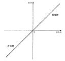
- the output is linear with respect to manual input as shown in FIG. , Smooth characteristics.
- the discontinuity near the steering wheel center is eliminated, and the steering feeling is improved.
- one system is used, for example, for control of the right steering region
- the other system is used for control of left steering.
- the offset F1 is almost flat up to a predetermined value Ta, and as the manual input (steering torque) exceeds the predetermined value Ta,
- the current steering current command value characteristic RH gradually increases.
- the left steering current command value characteristic LH gradually increases.
- the right steering and the left steering may be reversed, and the absolute value
- may be different or the same, and the offset F1 and the offset F1 may be different (not (Equilibrium) or the same (equilibrium).
- the unbalance is set.
- the change characteristics of the right steering current command value characteristic RH and the left steering current command value characteristic LH are variable, and the respective characteristics can be freely set.
- the discrimination between right steering and left steering is performed as shown in FIG. 7, and the configuration is the same as in FIG.
- the MCU 500 discriminates left and right steering based on the input steering torque Ts, steering angle ⁇ , vehicle speed Vs, etc., sets the right steering offset F1 or the left steering offset F2, and further controls the right steering current command value Iref1.
- the left steering current command value Iref2 is calculated.
- the right steering current command value Iref1 has a characteristic RH as shown in FIG. 13, for example, and the left steering current command value Iref2 has a characteristic LH.
- the right steering current command value Iref1 is not zero but has a predetermined offset F1
- the left steering current command value Iref2 is not zero and has a predetermined offset F2. That is, in the vicinity of the handle center, both the first system and the second system of the motor are driven. Accordingly, there is no dead zone in the vicinity of the steering wheel center, the right steering and the left steering are driven individually, and the steering does not become discontinuous due to an inflection point or the like.
- Each of the offset F1 of the right steering current command value Iref1 and the offset F2 of the left steering current command value Iref2 has the characteristics shown in FIG. 9, and rapidly decreases when the vehicle speed Vs is low as shown in FIG. Further, it may have a characteristic of gradually decreasing when the vehicle speed becomes high.
- Embodiment 2 there is no dead zone in the vicinity of the handle center of the electric system, and control is performed so that the right steering and the left steering are unbalanced.
- the output is linear and there is no discontinuity near the handle center, resulting in smooth characteristics.
- the MCU 500 includes a steering direction determination unit 510, offset calculation units 520 and 550, a current command value generation unit 560, and a SAT detection unit 570.
- the steering direction determination unit 510 receives the steering angle ⁇ and the rotation angle RS, calculates the angular velocity ⁇ from the rotation angle RS, and uses the steering angle ⁇ and the angular velocity ⁇ according to the classification shown in FIG. Right steering).
- the determination result SD is output to the current command value generation unit 560.
- the SAT detection unit 570 detects the SAT value ST and outputs it to the offset calculation units 520 and 550 and the current command value generation unit 560.
- the SAT value ST may be detected by providing a SAT sensor, or may be estimated based on the steering torque Ts, the angular velocity ⁇ , or the like.
- the offset calculation unit 520 is configured as shown in FIG. 16, and inputs the vehicle speed Vs, the rotation angle RS, and the SAT value ST, and calculates the offset F1.
- the offset calculation unit 520 includes a rectilinear determination unit 521 that determines whether the vehicle is traveling straight based on the vehicle speed Vs, the rotation angle RS, and the SAT value ST, and the determination signal Flg from the rectilinear determination unit 521 is input to the switch 526 and contacts. 526a and 526b are switched.
- the offset gain OG output from the offset gain unit 522 is input to the contact 526a of the switch 526.
- the determination signal Flg is “1”. These contacts can be switched to a contact 526a.
- the configuration of the straight traveling determination unit 521 is, for example, as shown in FIG. 17, the vehicle speed Vs is input to the comparison unit 543 that compares with the threshold value Vth, and the rotation angle RS is converted to an absolute value by the absolute value unit 541 and the threshold value
- the SAT value ST is input to the comparison unit 544 that compares with RS th, and the SAT value ST is converted to an absolute value by the absolute value unit 542 and input to the comparison unit 545 that compares the threshold value ST th .
- the comparison results of the comparison units 543 to 545 are determined by the determination unit 546.
- the determination unit 546 When all the comparison results of the comparison units 543 to 545 satisfy the conditions, the determination unit 546 outputs the straight traveling signal YS and measures the time by the straight traveling signal YS. The counter 547 is counted up, and the count value Cnt is input to the comparison unit 548 that compares the threshold value C1. The comparison result RC of the comparison unit 548 is input to the determination signal output unit 549.
- the determination unit 546 outputs the non-straight-ahead signal NS, and the non-straight-ahead signal NS resets the time counter 547 and the determination signal output unit 549. Is input.
- the determination signal output unit 549 outputs a determination signal Flg based on the non-straight forward signal NS and the comparison result RC.
- the offset gain unit 522 outputs an offset gain OG in response to the SAT value ST.
- FIG. 18A shows an example of gain characteristics of the offset gain unit 522. When the SAT value ST is zero, the offset gain OG is zero, and when the SAT value ST is increased, the offset gain OG is also increased.
- the offset calculation unit 520 includes a reset gain unit 523 that outputs a reset gain RG in response to the SAT value ST and the rotation angle RS.
- the reset gain RG is input to the multiplication unit 529, and the multiplication result MR is the switch 526. Is input to the contact 526b.
- the determination signal Flg is “0”, and the contact of the switch 526 is switched to the contact 526b.
- FIG. 19 shows an example of the gain characteristic of the reset gain unit 523, which has an output gain characteristic that increases the reset gain RG regardless of which of the SAT value ST and the rotation angle RS increases.
- the output of the switch 526 is input to the adder 530, and the addition result is input to the adder 531 and to the memory unit 527 that stores and holds the value before one sampling.
- the value before one sampling from the memory unit 527 is input to the adder 530 and added, and the sign is inverted by the inverter 528 and input to the multiplier 529.
- a multiplication result MR with the reset gain RG in the multiplication unit 529 is input to the contact 526 b of the switch 526.
- the addition result obtained by adding the offset initial value 524 by the adder 531 is input to the limiter 525, and the signal limited by the limiter 525 is output as the offset F1.
- the offset calculation unit 550 has the same configuration as the offset calculation unit 520, and inputs the vehicle speed Vs, the rotation angle RS, and the SAT value ST, and calculates the offset F2.
- the offset gain unit has a gain characteristic different from that of the offset calculation unit 520. Is different.
- FIG. 18B shows an example of the gain characteristic of the offset gain section of the offset calculation section 550. When the SAT value ST is zero, the offset gain OG is zero, and when the SAT value ST increases, the offset gain OG decreases. .
- the current command value generation unit 560 includes, for example, a current command value calculation unit, a current limiting unit, a compensation signal generation unit, an addition unit, and a subtraction unit illustrated in FIG.
- the current command value Iref calculated by the current command value calculation unit of the current command value generation unit 560 has a characteristic as shown in, for example, FIG. 6 or FIG. 13, and the offset F1 output from the offset calculation unit 520 and The offset F2 output from the offset calculation unit 550 is used.
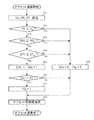
- the steering direction determination unit 510 reads the steering angle ⁇ and the rotation angle RS, calculates the angular velocity ⁇ from the rotation angle RS, determines the steering direction according to the division shown in FIG. , Right steering) is output (step S1).
- the SAT detector 570 detects the SAT value ST and outputs it to the offset calculators 520 and 550 and the current command value generator 560 (step S2).
- the offset calculation unit 520 calculates the offset F1 using the vehicle speed Vs, the rotation angle RS, and the SAT value ST (step S3).
- the straight traveling determination unit 521 first reads the vehicle speed Vs, the rotation angle RS, and the SAT value ST (step S31).
- the SAT value ST is also input to the offset gain unit 522 and the reset gain unit 523, and the rotation angle RS is also input to the reset gain unit 523.
- Vehicle speed Vs that has been read into the straight travel determination unit 521 is input to the comparator 543, the comparison unit 543 determines whether the vehicle speed Vs is the threshold value V th or more (step S32), the vehicle speed Vs is greater than or equal to the threshold V th In this case, it is determined whether or not the absolute value
- the vehicle speed Vs is high, the straight traveling state can be accurately detected. In the straight traveling state, the determination is generally based on the small rotation angle and SAT.
- the order of steps S32 to S34 is arbitrary and can be changed as appropriate.
- the comparison results of the comparison units 543 to 545 are input to the determination unit 546.
- the determination unit 546 outputs the straight-ahead signal YS, and the count value Cnt of the time counter 547 that measures the passage of time. Is incremented by “+1” (step S35), and the comparison unit 548 determines whether or not the count value Cnt has become larger than the threshold value C1, that is, whether or not a predetermined time has elapsed (step S36).
- the comparison unit 548 When the count value Cnt is greater than the threshold value C1 and a predetermined time has elapsed, the comparison unit 548 outputs the comparison result RC to the determination signal output unit 549, and the determination signal output unit 549 sets the determination signal Flg to “1” ( Step S37), the contact of the switch 526 is switched to 526a. Then, the offset gain OG set by the offset gain unit 522 with the characteristics shown in FIG. 18A using the SAT value ST is input to the adding unit 530 through the switch 526, and the data before one sampling of the memory unit 527 is stored. The values are added and input to the adder 531.
- step S32 if the vehicle speed Vs is a threshold value V th is less than, or in step S33, the absolute value of the rotation angle RS
- the count value Cnt of the time counter 547 is reset to 0, the determination signal Flg output from the determination signal output unit 549 is set to “0”, and the contact of the switch 526 is switched to the contact 526b (step S38). ).
- the data before one sampling of the memory unit 527 is inverted in sign by the inverting unit 528 and input to the multiplying unit 529, and the reset gain 523 is multiplied by the reset gain RG set with the characteristics shown in FIG.
- the multiplication result MR is input to the adder 530 through the switch 526 and further input to the adder 531. In this case, the vehicle moves away from the straight traveling state, and the offset gain OG gradually approaches zero and finally becomes zero.
- the offset initial value 524 is added in the adder 531 (step S39), the maximum value and the minimum value (values greater than 0) are limited by the limiter 525, and output as the offset F1.
- the offset calculation unit 550 calculates the offset F2 using the vehicle speed Vs, the rotation angle RS, and the SAT value ST (step S4). Since the calculation of the offset F2 is the same process as the calculation of the offset F1, the description thereof is omitted. In the offset gain setting of the offset gain section, the characteristics shown in FIG. 18B are used.
- the current command value generation unit 560 uses, for example, the offset F1 output from the offset calculation unit 520 and the offset F2 output from the offset calculation unit 550 to change the characteristic as illustrated in FIG. 6 or FIG. 13 to the current command value Iref.
- the right steering current command value Iref1 and / or the left steering current command value Iref2 are output based on the determination result SD output from the steering direction determination unit 510 (step S5).
- both the right steering current command value Iref1 and the left steering current command value Iref2 are not zero, so that both the first system and the second system of the motor are driven. Accordingly, there is no dead zone in the vicinity of the steering wheel center, the right steering and the left steering are driven individually, and the steering does not become discontinuous due to an inflection point or the like.
- the gain characteristic of the offset gain unit 522 of the offset calculation unit 520 may be a characteristic such that the offset gain becomes zero when the SAT value ST is equal to or less than zero, as shown in FIG.
- the gain characteristic of the offset gain section of the offset calculation section 550 may be a characteristic that the offset gain becomes zero when the SAT value ST is zero or more, as shown in FIG. In this case, only the offset F1 changes in the right steering region where the acting force (for example, SAT value) is positive, and only the offset F2 changes in the left steering region where the acting force is negative.
- the gain characteristic of the offset gain unit 522 of the offset calculation unit 520 is a characteristic in which the offset gain becomes zero when the SAT value ST is zero or more as shown in FIG.
- the gain characteristic may be such that the offset gain becomes zero when the SAT value ST is equal to or less than zero as shown in FIG. In this case, only the offset F2 changes in the right steering region where the acting force is in the positive direction, and only the offset F1 changes in the left steering region where the acting force is in the negative direction. Further, the gain characteristic of the offset gain unit 522 of the offset calculation unit 520 and the gain characteristic of the offset gain unit of the offset calculation unit 550 do not have to have the same rate of change (the absolute value of the slope of the straight line). It may change to a curved line. By setting it as such a characteristic, suitable adjustment according to driving
- the offset F1 and the offset F2 change according to the SAT value, but may be variable according to the vehicle speed in addition to the SAT value.
- a function is added to the offset calculation unit so that the offset is variable according to the vehicle speed.
- FIG. 23 shows a block diagram of a configuration example (Example 2) of the offset calculation unit to which this function is added.
- a vehicle speed sensitive gain unit 532 and a multiplication unit 533 are added to the offset calculation unit 520 of the first embodiment illustrated in FIG. 16, and other configurations are the same as those of the first embodiment. Since the operation of the same configuration as the embodiment is the same, the description is omitted.
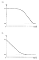
- the vehicle speed sensitive gain unit 532 outputs a vehicle speed gain VG in response to the vehicle speed Vs.
- FIG. 24A shows an example of the gain characteristic of the vehicle speed sensitive gain unit 532, which has a characteristic that it gently decreases when the vehicle speed Vs is low and rapidly decreases when the vehicle speed becomes high.
- FIG. 24B there may be a characteristic that the vehicle speed Vs decreases rapidly when the vehicle speed is low and gradually decreases when the vehicle speed becomes high.
- the offset calculation unit 580 receives the vehicle speed Vs, the rotation angle RS, and the SAT value ST and calculates the offset F1 as in the offset calculation unit 520.
- the offset F1 whose maximum value and minimum value are limited by the limiter 525 is multiplied by the vehicle speed gain VG by the multiplier 533 and output.
- the vehicle speed gain is also multiplied by the same configuration and operation for the offset F2.
- the SAT value ST is used as the acting force applied to the steering mechanism, but the steering torque Ts may be used.
- FIG. 25 shows a configuration example of the MCU when the steering torque Ts is used as the acting force.
- the SAT detection unit 570 is deleted from the MCU 500 shown in FIG. 15, and the offset calculation unit is replaced with the SAT value ST.
- the steering torque Ts is input to Therefore, the steering torque Ts is input instead of the SAT value ST to the straight traveling determination unit, the offset gain unit, and the reset gain unit shown in FIG.
- Other configurations are the same as those of the embodiment of FIG. Since it is not necessary to detect SAT, the configuration becomes simpler.
- the operations of the offset calculators 620 and 650 differ from the offset calculators 520 and 550 of FIG. 15 only in that the steering torque Ts is used instead of the SAT value ST, and the other operations are completely the same. A similar effect can be obtained.
- the output is linear with respect to manual input, and has smooth characteristics.
- the discontinuity near the steering wheel center is eliminated, and the steering feeling is improved.
- the offset of the current command value is adjusted, so that the output characteristics with respect to the manual input shift as shown in FIG. 26B, for example, and the output is corrected. This reduces the burden on the driver.
- the MCU has two offset calculation units, but the offsets F1 and F2 may be calculated by one offset calculation unit. Thereby, a structure can be simplified.
- a motor having two-system motor windings has been described as an example.
- the present invention can also be applied to a motor having three or more multi-system motors.
- the motor is driven and controlled by the GDM, but the configuration may be a PI control unit, a PWM control unit, an inverter, or the like.
- the above description of the left / right steering may be reversed.
Landscapes
- Engineering & Computer Science (AREA)
- Chemical & Material Sciences (AREA)
- Combustion & Propulsion (AREA)
- Transportation (AREA)
- Mechanical Engineering (AREA)
- Power Engineering (AREA)
- Power Steering Mechanism (AREA)
- Steering Control In Accordance With Driving Conditions (AREA)
- Control Of Ac Motors In General (AREA)
Abstract
Priority Applications (4)
| Application Number | Priority Date | Filing Date | Title |
|---|---|---|---|
| US15/519,581 US9896121B2 (en) | 2014-12-25 | 2015-12-25 | Electric power steering apparatus |
| CN201580076881.8A CN107406098B (zh) | 2014-12-25 | 2015-12-25 | 电动助力转向装置 |
| EP15873249.5A EP3208179B1 (fr) | 2014-12-25 | 2015-12-25 | Dispositif de direction à assistance électrique |
| JP2016535192A JP5999291B1 (ja) | 2014-12-25 | 2015-12-25 | 電動パワーステアリング装置 |
Applications Claiming Priority (6)
| Application Number | Priority Date | Filing Date | Title |
|---|---|---|---|
| JP2014262994 | 2014-12-25 | ||
| JP2014-262994 | 2014-12-25 | ||
| JP2015055890 | 2015-03-19 | ||
| JP2015-055890 | 2015-03-19 | ||
| JP2015123076 | 2015-06-18 | ||
| JP2015-123076 | 2015-06-18 |
Publications (1)
| Publication Number | Publication Date |
|---|---|
| WO2016104681A1 true WO2016104681A1 (fr) | 2016-06-30 |
Family
ID=56150693
Family Applications (1)
| Application Number | Title | Priority Date | Filing Date |
|---|---|---|---|
| PCT/JP2015/086182 Ceased WO2016104681A1 (fr) | 2014-12-25 | 2015-12-25 | Dispositif de direction à assistance électrique |
Country Status (5)
| Country | Link |
|---|---|
| US (1) | US9896121B2 (fr) |
| EP (1) | EP3208179B1 (fr) |
| JP (1) | JP5999291B1 (fr) |
| CN (1) | CN107406098B (fr) |
| WO (1) | WO2016104681A1 (fr) |
Cited By (2)
| Publication number | Priority date | Publication date | Assignee | Title |
|---|---|---|---|---|
| KR102049923B1 (ko) * | 2018-08-27 | 2019-11-28 | 현대모비스 주식회사 | 엠디피에스 시스템의 제어 장치 및 방법 |
| WO2021075054A1 (fr) * | 2019-10-18 | 2021-04-22 | 日産自動車株式会社 | Procédé de détermination d'annulation pour un dispositif d'aide au déplacement et dispositif d'aide au déplacement |
Families Citing this family (7)
| Publication number | Priority date | Publication date | Assignee | Title |
|---|---|---|---|---|
| JP6326171B1 (ja) * | 2017-07-20 | 2018-05-16 | 株式会社ショーワ | 操舵制御装置、電動パワーステアリング装置 |
| DE102019200971B4 (de) * | 2018-02-05 | 2025-07-10 | Denso Corporation | Lenksteuerungsvorrichtung |
| DE102018103082B4 (de) * | 2018-02-12 | 2023-09-21 | Thyssenkrupp Ag | Verfahren zur Bereitstellung einer Lenkkraftunterstützung für ein elektromechanisches Lenksystem eines Kraftfahrzeuges mit einem redundant ausgelegten Steuergerät |
| DE102018114828B3 (de) | 2018-06-20 | 2019-07-25 | Thyssenkrupp Ag | Kraftfahrzeuglenkung mit einem redundant ausgelegten Steuergerät |
| JP2022114555A (ja) * | 2021-01-27 | 2022-08-08 | Ntn株式会社 | 操舵システムおよびこれを備えた車両 |
| DE102021201141A1 (de) * | 2021-02-08 | 2022-08-11 | Continental Automotive Gmbh | Regelungseinrichtung und Verfahren zur Lenkwinkelregelung eines Fahrzeugs |
| CN113581281B (zh) * | 2021-08-30 | 2022-07-26 | 中汽创智科技有限公司 | 一种车辆转向控制方法、装置、设备及存储介质 |
Citations (4)
| Publication number | Priority date | Publication date | Assignee | Title |
|---|---|---|---|---|
| JP2004001643A (ja) * | 2002-05-31 | 2004-01-08 | Mitsubishi Electric Corp | 電動パワーステアリング制御装置 |
| US20060032696A1 (en) * | 2004-08-16 | 2006-02-16 | Phillips Edward H | Hydro-mechanically coupled electric power steering system |
| JP2014176215A (ja) * | 2013-03-08 | 2014-09-22 | Nsk Ltd | モータ制御装置、これを使用した電動パワーステアリング装置及び車両 |
| JP2014201198A (ja) * | 2013-04-04 | 2014-10-27 | トヨタ自動車株式会社 | 電動パワーステアリング装置 |
Family Cites Families (21)
| Publication number | Priority date | Publication date | Assignee | Title |
|---|---|---|---|---|
| US5528497A (en) * | 1992-09-16 | 1996-06-18 | Honda Giken Kogyo Kabushiki Kaisha | Vehicle steering control system |
| US20040264075A1 (en) * | 2003-06-30 | 2004-12-30 | Valeo Electrical Systems, Inc. | Steering assist system |
| JP5011757B2 (ja) * | 2005-08-02 | 2012-08-29 | 日産自動車株式会社 | 車両用操舵装置 |
| JP4940709B2 (ja) | 2006-03-07 | 2012-05-30 | 日産自動車株式会社 | 操舵制御装置、自動車及び操舵制御方法 |
| GB0620143D0 (en) * | 2006-10-11 | 2006-11-22 | Trw Lucasvarity Electric Steer | Electric power assisted steering assembly |
| JP5034633B2 (ja) * | 2006-10-17 | 2012-09-26 | 日本精工株式会社 | モータ駆動制御装置、モータ駆動制御方法及びモータ駆動制御装置を使用した電動パワーステアリング装置 |
| US9802644B2 (en) * | 2010-11-29 | 2017-10-31 | Honda Motor Co., Ltd. | Electronic power steering apparatus |
| JP2012131471A (ja) * | 2010-11-29 | 2012-07-12 | Honda Motor Co Ltd | 電動ステアリング装置 |
| JP5440889B2 (ja) * | 2012-01-10 | 2014-03-12 | 株式会社デンソー | 電動パワーステアリング装置 |
| EP2803556B1 (fr) * | 2012-01-11 | 2017-12-13 | Mitsubishi Electric Corporation | Dispositif électrique de direction assistée |
| JP5653386B2 (ja) * | 2012-05-09 | 2015-01-14 | 三菱電機株式会社 | モータ制御装置およびそれを用いた電動パワーステアリング装置 |
| JP5925114B2 (ja) | 2012-12-18 | 2016-05-25 | 三菱電機株式会社 | モータ駆動装置、多重巻線モータ、及び電動パワーステアリング装置 |
| JP6022951B2 (ja) * | 2013-01-18 | 2016-11-09 | トヨタ自動車株式会社 | 電動パワーステアリング装置 |
| CN104981973B (zh) * | 2013-02-12 | 2018-02-16 | 三菱电机株式会社 | 电动机驱动装置 |
| JP5932147B2 (ja) * | 2013-05-31 | 2016-06-08 | 三菱電機株式会社 | 多重多相巻線交流回転電機および電動パワーステアリング装置 |
| CN105705401B (zh) * | 2013-11-08 | 2018-05-29 | 三菱电机株式会社 | 电动助力转向控制装置及电动助力转向控制方法 |
| JP6362349B2 (ja) * | 2014-02-19 | 2018-07-25 | 日立オートモティブシステムズ株式会社 | 電動モータの駆動制御装置 |
| JP6220696B2 (ja) * | 2014-02-19 | 2017-10-25 | 日立オートモティブシステムズ株式会社 | 電動モータの駆動制御装置 |
| JP6283737B2 (ja) * | 2014-03-19 | 2018-02-21 | 日立オートモティブシステムズ株式会社 | パワーステアリング装置およびパワーステアリング装置の制御装置 |
| EP3121957A4 (fr) * | 2014-03-19 | 2018-03-21 | Mitsubishi Electric Corporation | Dispositif de commande de machine rotative ca et dispositif de direction assistée électrique |
| JP6299574B2 (ja) * | 2014-12-04 | 2018-03-28 | 株式会社デンソー | 電子装置 |
-
2015
- 2015-12-25 US US15/519,581 patent/US9896121B2/en active Active
- 2015-12-25 EP EP15873249.5A patent/EP3208179B1/fr active Active
- 2015-12-25 WO PCT/JP2015/086182 patent/WO2016104681A1/fr not_active Ceased
- 2015-12-25 JP JP2016535192A patent/JP5999291B1/ja active Active
- 2015-12-25 CN CN201580076881.8A patent/CN107406098B/zh active Active
Patent Citations (4)
| Publication number | Priority date | Publication date | Assignee | Title |
|---|---|---|---|---|
| JP2004001643A (ja) * | 2002-05-31 | 2004-01-08 | Mitsubishi Electric Corp | 電動パワーステアリング制御装置 |
| US20060032696A1 (en) * | 2004-08-16 | 2006-02-16 | Phillips Edward H | Hydro-mechanically coupled electric power steering system |
| JP2014176215A (ja) * | 2013-03-08 | 2014-09-22 | Nsk Ltd | モータ制御装置、これを使用した電動パワーステアリング装置及び車両 |
| JP2014201198A (ja) * | 2013-04-04 | 2014-10-27 | トヨタ自動車株式会社 | 電動パワーステアリング装置 |
Cited By (4)
| Publication number | Priority date | Publication date | Assignee | Title |
|---|---|---|---|---|
| KR102049923B1 (ko) * | 2018-08-27 | 2019-11-28 | 현대모비스 주식회사 | 엠디피에스 시스템의 제어 장치 및 방법 |
| WO2021075054A1 (fr) * | 2019-10-18 | 2021-04-22 | 日産自動車株式会社 | Procédé de détermination d'annulation pour un dispositif d'aide au déplacement et dispositif d'aide au déplacement |
| JPWO2021075054A1 (fr) * | 2019-10-18 | 2021-04-22 | ||
| JP7173371B2 (ja) | 2019-10-18 | 2022-11-16 | 日産自動車株式会社 | 走行支援装置のオーバーライド判定方法、及び走行支援装置 |
Also Published As
| Publication number | Publication date |
|---|---|
| EP3208179B1 (fr) | 2020-02-19 |
| US9896121B2 (en) | 2018-02-20 |
| JPWO2016104681A1 (ja) | 2017-04-27 |
| CN107406098A (zh) | 2017-11-28 |
| EP3208179A1 (fr) | 2017-08-23 |
| US20170282966A1 (en) | 2017-10-05 |
| JP5999291B1 (ja) | 2016-09-28 |
| EP3208179A4 (fr) | 2018-08-15 |
| CN107406098B (zh) | 2020-04-07 |
Similar Documents
| Publication | Publication Date | Title |
|---|---|---|
| JP5999291B1 (ja) | 電動パワーステアリング装置 | |
| JP6477995B1 (ja) | 電動パワーステアリング装置 | |
| US10526009B2 (en) | Electric power steering apparatus | |
| CN111315637B (zh) | 电动助力转向装置 | |
| JP5971426B2 (ja) | 電動パワーステアリング装置 | |
| US8272474B2 (en) | Electric power steering system | |
| US11377141B2 (en) | Electric power steering device | |
| US11091196B2 (en) | Steering control device | |
| JP6115368B2 (ja) | ステアリング装置 | |
| WO2016017234A1 (fr) | Dispositif de direction à assistance électrique | |
| JP6020776B2 (ja) | 電動パワーステアリング装置 | |
| CN106458254B (zh) | 电动助力转向装置 | |
| CN107531275A (zh) | 电动助力转向装置 | |
| JP5975193B2 (ja) | 電動パワーステアリング装置 | |
| JP2014040179A (ja) | 電動パワーステアリング装置 | |
| JP6565847B2 (ja) | 電動パワーステアリング装置 | |
| EP2700564A2 (fr) | Appareil de direction assistée électronique | |
| JP5556219B2 (ja) | 電動パワーステアリング装置 | |
| EP4052993B1 (fr) | Dispositif de commande et dispositif de direction assistée électrique | |
| US20070290639A1 (en) | Motor controller | |
| JP2008230580A (ja) | 電動パワーステアリング装置 | |
| JP2009065773A (ja) | モータ駆動制御装置 | |
| JP2008056079A (ja) | モータ制御装置 | |
| JP2008221929A (ja) | 電動パワーステアリング装置の制御装置 | |
| JP2006327382A (ja) | 電動パワーステアリング装置 |
Legal Events
| Date | Code | Title | Description |
|---|---|---|---|
| ENP | Entry into the national phase |
Ref document number: 2016535192 Country of ref document: JP Kind code of ref document: A |
|
| 121 | Ep: the epo has been informed by wipo that ep was designated in this application |
Ref document number: 15873249 Country of ref document: EP Kind code of ref document: A1 |
|
| WWE | Wipo information: entry into national phase |
Ref document number: 15519581 Country of ref document: US |
|
| REEP | Request for entry into the european phase |
Ref document number: 2015873249 Country of ref document: EP |
|
| NENP | Non-entry into the national phase |
Ref country code: DE |