WO2016110962A1 - ガス遮断器 - Google Patents
ガス遮断器 Download PDFInfo
- Publication number
- WO2016110962A1 WO2016110962A1 PCT/JP2015/050275 JP2015050275W WO2016110962A1 WO 2016110962 A1 WO2016110962 A1 WO 2016110962A1 JP 2015050275 W JP2015050275 W JP 2015050275W WO 2016110962 A1 WO2016110962 A1 WO 2016110962A1
- Authority
- WO
- WIPO (PCT)
- Prior art keywords
- arc contact
- movable
- fixed
- insulating material
- contact
- Prior art date
- Legal status (The legal status is an assumption and is not a legal conclusion. Google has not performed a legal analysis and makes no representation as to the accuracy of the status listed.)
- Ceased
Links
Images



Classifications
-
- H—ELECTRICITY
- H01—ELECTRIC ELEMENTS
- H01H—ELECTRIC SWITCHES; RELAYS; SELECTORS; EMERGENCY PROTECTIVE DEVICES
- H01H33/00—High-tension or heavy-current switches with arc-extinguishing or arc-preventing means
- H01H33/70—Switches with separate means for directing, obtaining, or increasing flow of arc-extinguishing fluid
- H01H33/88—Switches with separate means for directing, obtaining, or increasing flow of arc-extinguishing fluid the flow of arc-extinguishing fluid being produced or increased by movement of pistons or other pressure-producing parts
- H01H33/90—Switches with separate means for directing, obtaining, or increasing flow of arc-extinguishing fluid the flow of arc-extinguishing fluid being produced or increased by movement of pistons or other pressure-producing parts this movement being effected by or in conjunction with the contact-operating mechanism
- H01H33/91—Switches with separate means for directing, obtaining, or increasing flow of arc-extinguishing fluid the flow of arc-extinguishing fluid being produced or increased by movement of pistons or other pressure-producing parts this movement being effected by or in conjunction with the contact-operating mechanism the arc-extinguishing fluid being air or gas
-
- H—ELECTRICITY
- H01—ELECTRIC ELEMENTS
- H01H—ELECTRIC SWITCHES; RELAYS; SELECTORS; EMERGENCY PROTECTIVE DEVICES
- H01H33/00—High-tension or heavy-current switches with arc-extinguishing or arc-preventing means
- H01H33/02—Details
- H01H33/04—Means for extinguishing or preventing arc between current-carrying parts
- H01H33/08—Stationary parts for restricting or subdividing the arc, e.g. barrier plate
-
- H—ELECTRICITY
- H01—ELECTRIC ELEMENTS
- H01H—ELECTRIC SWITCHES; RELAYS; SELECTORS; EMERGENCY PROTECTIVE DEVICES
- H01H33/00—High-tension or heavy-current switches with arc-extinguishing or arc-preventing means
- H01H33/70—Switches with separate means for directing, obtaining, or increasing flow of arc-extinguishing fluid
- H01H33/76—Switches with separate means for directing, obtaining, or increasing flow of arc-extinguishing fluid wherein arc-extinguishing gas is evolved from stationary parts; Selection of material therefor
-
- H—ELECTRICITY
- H01—ELECTRIC ELEMENTS
- H01H—ELECTRIC SWITCHES; RELAYS; SELECTORS; EMERGENCY PROTECTIVE DEVICES
- H01H33/00—High-tension or heavy-current switches with arc-extinguishing or arc-preventing means
- H01H33/70—Switches with separate means for directing, obtaining, or increasing flow of arc-extinguishing fluid
- H01H33/88—Switches with separate means for directing, obtaining, or increasing flow of arc-extinguishing fluid the flow of arc-extinguishing fluid being produced or increased by movement of pistons or other pressure-producing parts
- H01H33/90—Switches with separate means for directing, obtaining, or increasing flow of arc-extinguishing fluid the flow of arc-extinguishing fluid being produced or increased by movement of pistons or other pressure-producing parts this movement being effected by or in conjunction with the contact-operating mechanism
- H01H33/901—Switches with separate means for directing, obtaining, or increasing flow of arc-extinguishing fluid the flow of arc-extinguishing fluid being produced or increased by movement of pistons or other pressure-producing parts this movement being effected by or in conjunction with the contact-operating mechanism making use of the energy of the arc or an auxiliary arc
-
- H—ELECTRICITY
- H01—ELECTRIC ELEMENTS
- H01H—ELECTRIC SWITCHES; RELAYS; SELECTORS; EMERGENCY PROTECTIVE DEVICES
- H01H33/00—High-tension or heavy-current switches with arc-extinguishing or arc-preventing means
- H01H33/70—Switches with separate means for directing, obtaining, or increasing flow of arc-extinguishing fluid
- H01H33/88—Switches with separate means for directing, obtaining, or increasing flow of arc-extinguishing fluid the flow of arc-extinguishing fluid being produced or increased by movement of pistons or other pressure-producing parts
- H01H33/90—Switches with separate means for directing, obtaining, or increasing flow of arc-extinguishing fluid the flow of arc-extinguishing fluid being produced or increased by movement of pistons or other pressure-producing parts this movement being effected by or in conjunction with the contact-operating mechanism
- H01H33/905—Switches with separate means for directing, obtaining, or increasing flow of arc-extinguishing fluid the flow of arc-extinguishing fluid being produced or increased by movement of pistons or other pressure-producing parts this movement being effected by or in conjunction with the contact-operating mechanism the compression volume being formed by a movable cylinder and a semi-mobile piston
-
- H—ELECTRICITY
- H01—ELECTRIC ELEMENTS
- H01H—ELECTRIC SWITCHES; RELAYS; SELECTORS; EMERGENCY PROTECTIVE DEVICES
- H01H33/00—High-tension or heavy-current switches with arc-extinguishing or arc-preventing means
- H01H33/70—Switches with separate means for directing, obtaining, or increasing flow of arc-extinguishing fluid
- H01H33/88—Switches with separate means for directing, obtaining, or increasing flow of arc-extinguishing fluid the flow of arc-extinguishing fluid being produced or increased by movement of pistons or other pressure-producing parts
- H01H33/90—Switches with separate means for directing, obtaining, or increasing flow of arc-extinguishing fluid the flow of arc-extinguishing fluid being produced or increased by movement of pistons or other pressure-producing parts this movement being effected by or in conjunction with the contact-operating mechanism
- H01H2033/908—Switches with separate means for directing, obtaining, or increasing flow of arc-extinguishing fluid the flow of arc-extinguishing fluid being produced or increased by movement of pistons or other pressure-producing parts this movement being effected by or in conjunction with the contact-operating mechanism using valves for regulating communication between, e.g. arc space, hot volume, compression volume, surrounding volume
Definitions
- the present invention relates to a gas circuit breaker that interrupts current in an arc extinguishing gas.
- the gas circuit breaker increases the gas pressure of the arc extinguishing gas in the puffer chamber in order to extinguish the arc generated between the movable arc contact and the fixed arc contact when the current is interrupted. Blow sex gas on the arc.
- the mechanical puffer type gas circuit breaker compresses the arc extinguishing gas in the mechanical puffer chamber by mechanical operation, and extinguishes the arc by blowing high-pressure arc extinguishing gas to the arc. .
- the heat puffer type gas circuit breaker extinguishes the arc by blowing an arc extinguishing gas whose pressure is increased by the arc heat.
- a method using both a mechanical puffer type and a thermal puffer type has been put into practical use.
- the nozzle material used for spraying the arc-extinguishing gas is an ablation material such as polytetrafluoroethylene, evaporating gas is generated from the ablation material heated by the arc, and this evaporating gas is put into the puffer chamber.
- the ablation material is an insulating material that decomposes and evaporates by arc heat.
- the stator is formed in a rod shape and the movable contact is formed in a cylindrical shape, and an insulator made of an ablation material is attached to the tip of the fixed contact or the inner peripheral side of the movable contact.
- the described configuration is described.
- the gap between the movable contact and the fixed contact is originally a high electric field portion, in addition to the fixed contact.
- the present invention has been made in view of the above, and an object of the present invention is to provide a gas circuit breaker capable of improving current interruption performance while maintaining insulation performance.
- a gas circuit breaker includes a rod-like fixed arc contact, a cylindrical movable arc contact that contacts or separates from the fixed arc contact, and the fixed A puffer chamber in which arc extinguishing gas blown to the arc generated between the arc contact and the movable arc contact is stored, and a storage hole formed at one end of the fixed arc contact and the movable arc contact And at least a part of the other end surfaces of the fixed arc contact and the movable arc contact face the other side through an opening end formed at the tip, and the other end surface is the opening end.
- an insulating material made of ablative material that evaporates by heat.
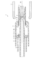
- FIG. 1 is a longitudinal cross-sectional view of the gas circuit breaker 1 according to the present embodiment in a charged state.
- FIG. 2 is a view in the charged state
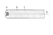
- FIG. 2 is a vertical cross-sectional view of the fixed arc contact 3
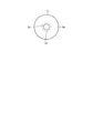
- FIG. 4 is a front view of the fixed arc contact 3
- FIG. 5 is a longitudinal sectional view of the gas circuit breaker 1 according to the present embodiment during a shut-off operation.
- the gas circuit breaker 1 includes a cylindrical fixed main contact 2, a rod-shaped fixed arc contact 3 disposed inside the fixed main contact 2, and a cylinder capable of reciprocating in the direction of the axis 25 as elements constituting a blocking unit.
- Rod 12 a bottomed cylindrical puffer cylinder 8 which is disposed so as to surround the rod 12 and is fixed to the rod 12, a piston 11 which is fitted into the puffer cylinder 8, and a puffer cylinder 8 which is fixed to the puffer
- a cylindrical puffer cylinder 7 disposed on the fixed arc contact 3 side of the cylinder 8 and a movable main fixed to the end of the puffer cylinder 7 on the fixed arc contact 3 side and capable of contacting or separating from the fixed main contact 2.
- the contact 4 is fixed to the end of the rod 12 on the fixed arc contact 3 side, and is disposed inside the movable main contact 4. Comprising fixed contact or with separable movable arc contact 5 and an arc contact 3, and a cylindrical nozzle 6 fixed to the inner peripheral surface of the movable main contact 4.
- the gas circuit breaker 1 is configured by housing the above-described interrupting part in a metal container (not shown) hermetically filled with an arc extinguishing gas.
- the arc extinguishing gas has arc extinguishing properties and insulation properties.
- the arc extinguishing gas is sulfur hexafluoride gas.
- the fixed main contact 2 is fixed to a fixed frame (not shown).
- the fixed main contact 2 is made of metal.
- the inner peripheral side of the distal end portion of the fixed main contact 2 is in contact with the outer peripheral side of the movable main contact 4.
- the tip of the fixed main contact 2 is the end of the fixed main contact 2 on the movable main contact 4 side.
- an alternating current flows between the fixed main contact 2 and the movable main contact 4.
- the central axis of the fixed main contact 2 coincides with the axis 25.
- the movable main contact 4 can reciprocate in the direction of the axis 25.
- the fixed arc contact 3 is fixed to the fixed side frame described above.
- the central axis of the fixed arc contact 3 coincides with the axis 25.
- the fixed arc contact 3 extends in the direction of the axis 25.
- the movable arc contact 5 can reciprocate in the direction of the axis 25.
- the fixed arc contact 3 includes a columnar base portion 3a extending in the direction of the axis 25, and a tip portion 3b formed integrally with the base portion 3a and formed with a storage hole 14 opened to the movable arc contact 5 side.
- the tip 3b is an end of the fixed arc contact 3 on the movable arc contact 5 side.
- the fixed arc contact 3 is made of metal.
- the insulating material 15 is stored in the storage hole 14 formed in the tip 3b.
- the insulating material 15 is cylindrical.
- the storage hole 14 has a shape corresponding to the shape of the insulating material 15.
- the end surface 15 a on the movable arc contact 5 side of the insulating material 15 faces the movable arc contact 5 side through the open end 33 of the storage hole 14. Further, the end surface 15 a on the movable arc contact 5 side of the insulating material 15 is disposed inside the accommodation hole 14 with respect to the opening end 33. That is, the end surface 15 a is disposed on the fixed arc contact 3 side with respect to the opening end 33.
- the front end portion 3 b includes a holding portion 3 c that holds the insulating material 15 in the storage hole 14.
- the holding part 3 c is provided on the movable arc contact 5 side with respect to the insulating material 15. That is, the entire holding portion 3c is disposed closer to the movable arc contact 5 than the end surface 15a of the insulating material 15 on the movable arc contact 5 side.
- the holding part 3 c is annular in plan view from the movable arc contact 5 side and covers the outer peripheral edge part of the insulating material 15.
- the holding portion 3 c holds the insulating material 15 in the storage hole 14 so that the insulating material 15 does not move to the movable arc contact 5 side and fall out of the storage hole 14.
- maintenance part 3c is a vertical cross-sectional shape without a smooth corner.
- the insulating material 15 is formed from an ablation material.
- the ablation material is an insulating material that is decomposed and evaporated by the heat of the arc 30 to be evaporated gas when heated by the arc 30 generated between the fixed arc contact 3 and the movable arc contact 5.
- the ablation material constituting the insulating material 15 is a material that does not contain hydrogen atoms in the chemical structure and contains carbon-oxygen bonds in the main chain or cyclic structure.
- a perfluoroether polymer may be mentioned.
- specific examples of the perfluoroether polymer include compounds represented by the following chemical formula (1a), (1b), (1c), (2a), (2b) or (2c).
- a specific example of the ablation material in which the chemical structure does not include a hydrogen atom and the cyclic structure includes a carbon-oxygen bond includes 4-vinyloxy-1-butene cyclized polymer.
- Specific examples of the 4-vinyloxy-1-butene cyclized polymer include compounds represented by the following chemical formula (3), (4) or (5).
- the rod 12 is connected to an operating device (not shown) and can reciprocate in the direction of the shaft 25 by the operating force of the operating device.
- the rod 12 is formed from a metal.
- the piston 11 is fixed to a movable frame (not shown).
- the puffer cylinder 8 is interlocked with the rod 12.
- a space surrounded by the puffer cylinder 8, the piston 11 and the rod 12 serves as a mechanical puffer chamber 21.
- a space surrounded by the bottom portion 9 of the puffer cylinder 8, the puffer cylinder 7 and the rod 12 becomes a heat puffer chamber 20.
- the heat puffer chamber 20 and the mechanical puffer chamber 21 are arranged in series in the direction of the axis 25.
- the heat puffer chamber 20 and the mechanical puffer chamber 21 store arc extinguishing gas that is blown to the arc 30.
- the bottom 9 is provided with a check valve 10 in a communication hole that communicates the mechanical puffer chamber 21 and the thermal puffer chamber 20.
- the check valve 10 operates so that the arc extinguishing gas does not flow from the heat puffer chamber 20 to the mechanical puffer chamber 21.
- the piston 11 and the puffer cylinders 7 and 8 are made of metal.
- the central axis of the movable arc contact 5 coincides with the axis 25.
- the movable arc contact 5 is configured by annularly arranging a plurality of contact pieces around a shaft 25.
- the movable arc contact 5 is made of metal.
- the inner peripheral side of the tip of the movable arc contact 5 is in contact with the outer peripheral side of the fixed arc contact 3.
- the tip of the movable arc contact 5 is the end of the movable arc contact 5 on the fixed arc contact 3 side.
- the tip 3b of the fixed arc contact 3 does not contact the movable arc contact 5 and does not contribute to energization.
- the nozzle 6 is used for spraying the arc extinguishing gas and surrounds the movable arc contact 5 and the fixed arc contact 3.
- the nozzle 6 is formed from the ablation material described above.
- the insulating material 15 and the nozzle 6 are heated, and the ablation material described above is decomposed and evaporated by the heat of the arc 30 to generate evaporated gas.
- the evaporated gas flows into the heat puffer chamber 20 and increases the gas pressure in the heat puffer chamber 20. That is, in the heat puffer chamber 20, in addition to the sulfur hexafluoride gas that has been increased in pressure by the heat of the arc 30, evaporated gas that is decomposed and evaporated of the ablation material is contained. The gas pressure is increased.
- the ablation material does not contain hydrogen atoms in its chemical structure and contains a carbon-oxygen bond in the main chain or cyclic structure, so it is included in the main chain or cyclic structure by the heat of the arc 30.
- the carbon-oxygen bond is broken and decomposes and evaporates.
- the heating pressure increase in the arc space is reduced, and the arc extinguishing gas is blown from the heat puffer chamber 20 to the arc 30.
- the check valve 10 is opened, and the arc extinguishing gas in the mechanical puffer chamber 21 passes through the communication hole. Since it flows into the heat puffer chamber 20, the flow of the arc extinguishing gas blown from the heat puffer chamber 20 to the arc 30 is strengthened, and the arc 30 is easily extinguished.
- a storage hole 14 that opens to the movable arc contact 5 side is provided at the distal end portion 3 b of the fixed arc contact 3, an insulating material 15 made of an ablation material is stored in the storage hole 14, and the movable arc of the insulating material 15 is stored.
- the end surface 15 a on the contact 5 side is exposed to the movable arc contact 5 side through the opening end 33.
- the insulating material 15 is exposed to the arc 30, the amount of evaporation of the ablation material increases. Further, since the insulating material 15 is disposed adjacent to the arc space, the evaporated gas from the ablation material tends to flow into the heat puffer chamber 20. Therefore, the gas pressure in the heat puffer chamber 20 is further increased, and the current interruption performance is improved.
- the insulating material 15 is embedded in the distal end portion 3 b of the fixed arc contact 3.
- the tip 3b is a portion that does not contribute to energization, and the insulating material 15 does not affect the energization at the time of charging.
- the end surface 15 a on the movable arc contact 5 side of the insulating material 15 is disposed inside the accommodation hole 14 with respect to the opening end 33 of the accommodation hole 14.
- the end surface 15a of the insulating material 15 on the movable arc contact 5 side is disposed inside the storage hole 14 with respect to the opening end 33 of the storage hole 14, so A holding portion 3 c is provided that is disposed closer to the movable arc contact 5 than the insulating material 15.
- the insulating material 15 is held in the storage hole 14 by the holding portion 3c. Since the insulating material 15 is disposed at a position exposed to the arc 30 and the amount of evaporation of the ablation material is large, there is a possibility that the diameter of the insulating material 15 is reduced while repeating the shut-off operation. There is no risk of falling off 14.
- the insulating material 15 is rubbery and can be deformed. Therefore, the insulating material 15 can be configured to be slightly larger than the size of the storage hole 14 and stored by being pushed into the storage hole 14. Thereby, mounting
- the insulating material 15 can also be mounted in the storage hole 14 by pouring the ablation material into the storage hole 14 and casting it.
- the ablation material is a material that does not contain hydrogen atoms in the chemical structure and contains a carbon-oxygen bond in the main chain or cyclic structure.
- the carbon-oxygen bond contained in the main chain or the ring structure of the ablation material is broken by the heat of the arc 30, and the ablation material is efficiently decomposed and gasified, so that the amount of evaporation of the ablation material increases, and the heat buffer The gas pressure in the chamber 20 can be further increased.
- this ablation material does not contain hydrogen atoms, the evaporated gas does not react with sulfur hexafluoride gas to produce highly corrosive hydrogen fluoride.
- the ablation material is not limited to the above materials.
- the ablation material can be polytetrafluoroethylene.
- the ablation material may be different between the insulating material 15 and the nozzle 6.
- the gas pressure in the heat puffer chamber 20 is further increased by the evaporated gas from the ablation material, the output power of the operation device (not shown) is increased as in the prior art, and the mechanical puffer chamber 21 There is no need to increase the gas pressure. That is, according to the present embodiment, the current interruption performance can be improved without increasing the output of the operating device, and thus the cost can be reduced.
- the gas circuit breaker 1 has a mechanical puffer type and a thermal puffer type, but may be a mechanical puffer type or a thermal puffer type. That is, if the mechanical puffer chamber 21 is omitted from the configuration of FIG. Specifically, the piston 11 and the puffer cylinder 8 may be omitted, and the puffer cylinder 7 may be closed with an end plate corresponding to the bottom 9 without the check valve 10. Further, if the heat puffer chamber 20 is omitted from the configuration of FIG. Specifically, the bottom 9 may be omitted.
- the holding portion 3c is provided at the distal end portion 3b.
- a configuration in which the holding portion 3c is not provided is also possible. Even in this case, by disposing the end surface 15a on the movable arc contact 5 side of the insulating material 15 on the inner side of the storage hole 14 than the opening end 33 of the storage hole 14, the current interruption performance is suppressed while suppressing the deterioration of the insulation performance. Can be improved.
- the holding portion 3c does not have to be annular in a plan view from the movable arc contact 5 side, and may be divided in the circumferential direction. That is, as long as the end surface 15a on the movable arc contact 5 side of the insulating material 15 is disposed inside the storage hole 14 relative to the opening end 33 of the storage hole 14, the shape of the holding portion 3c is limited to an annular shape in the plan view. The shape which covers a part of outer edge part of the insulating material 15 may be sufficient.
- the shape of the insulating material 15 is a columnar shape, but it may be a columnar shape other than the columnar shape, and may be a shape other than the columnar shape.
- the arc extinguishing gas is sulfur hexafluoride gas, but other arc extinguishing gas may be used.
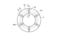
- FIG. FIG. 6 is a longitudinal sectional view of the movable arc contact 5 in the present embodiment
- FIG. 7 is a front view of the movable arc contact 5 in the present embodiment
- 6 is a longitudinal sectional view taken along line AA in FIG.
- the configuration of the movable arc contact 5 is the same as that of the first embodiment. That is, the configuration of the gas circuit breaker 1 is the same as the configuration shown in FIG. 1 or FIG.
- description will be made with reference to FIGS. 1 and 5 as well.
- the movable arc contact 5 is configured by arranging six contact pieces 5 a in a ring shape around a shaft 25.
- a slit 36 extending in the direction of the axis 25 is provided between the adjacent contact pieces 5a.
- the slit 36 is formed with a certain length from the fixed arc contact 3 side to the movable arc contact 5 side.
- the movable arc contact 5 is divided into six contact pieces 5 a by six slits 36 arranged in the circumferential direction around the shaft 25 and extending in the direction of the shaft 25.
- the six contact pieces 5a are integrated at the end opposite to the fixed arc contact 3 side.
- the movable arc contact 5 is formed integrally with the base portion 5b extending in the direction of the shaft 25 and the base portion 5b, and is thicker in the radial direction than the base portion 5b, and opens in the opposite side to the fixed arc contact 3 side. And a tip portion 5c formed with 35. The tip 5c is the end of the movable arc contact 5 on the fixed arc contact 3 side.
- the insulating material 40 is stored in the storage hole 35 formed in the tip portion 5c.
- the insulating material 40 is cylindrical.
- the storage hole 35 has a shape corresponding to the shape of the insulating material 40.
- a part of the end surface 40 a of the insulating material 40 on the fixed arc contact 3 side faces the fixed arc contact 3 side through the open end 38 of the slit 36 on the fixed arc contact 3 side. Further, the end face 40a is disposed on the opposite side of the open end 38 from the fixed arc contact 3 side.
- a cylindrical guide 41 is disposed on the inner peripheral surface of the base portion 5 b of the movable arc contact 5.
- the guide 41 is fixed to the base portion 5b.
- the guide 41 prevents the arc-extinguishing gas from being ejected from the thermal puffer chamber 20 through the slit 36, and guides the arc-extinguishing gas in the thermal puffer chamber 20 to the arc space.
- the guide 41 is also a holding portion that holds the insulating material 40 in the storage hole 35. That is, the end surface 41a of the guide 41 on the fixed arc contact 3 side faces the end surface 40b of the insulating material 40 opposite to the fixed arc contact 3 side, and the end portion of the guide 41 on the fixed arc contact 3 side is insulated.
- the material 40 is prevented from falling out of the storage hole 35.
- the distance in the direction of the axis 25 between the end surface 41a of the guide 41 on the fixed arc contact 3 side and the end surface 40b of the insulating material 40 on the opposite side to the fixed arc contact 3 side is Shorter than length.
- the end surface 41a of the guide 41 on the fixed arc contact 3 side and the end surface 40b of the insulating material 40 on the side opposite to the fixed arc contact 3 side may be in contact with each other.
- the guide 41 may be formed of a metal or an insulating material.
- the insulating material 40 is formed from an ablation material.
- the ablation material is an insulating material that is decomposed and evaporated by the heat of the arc 30 to be evaporated gas when heated by the arc 30 generated between the fixed arc contact 3 and the movable arc contact 5.
- the ablation material constituting the insulating material 40 is a material that does not contain hydrogen atoms in the chemical structure and contains carbon-oxygen bonds in the main chain or cyclic structure.
- a perfluoroether-based polymer can be given.
- a specific example of the ablation material in which the chemical structure does not include a hydrogen atom and the cyclic structure includes a carbon-oxygen bond includes 4-vinyloxy-1-butene cyclized polymer.
- the insulating materials 15 and 40 and the nozzle 6 are heated, and the ablation material constituting the insulating materials 15 and 40 and the nozzle 6 is decomposed and evaporated by the heat of the arc 30, and evaporating gas is generated.
- the evaporated gas flows into the heat puffer chamber 20 and increases the gas pressure in the heat puffer chamber 20.
- the heating pressure increase in the arc space is reduced, and the arc extinguishing gas is blown from the heat puffer chamber 20 to the arc 30.
- the check valve 10 is opened, and the arc extinguishing gas in the mechanical puffer chamber 21 passes through the communication hole. Since it flows into the heat puffer chamber 20, the flow of the arc extinguishing gas blown from the heat puffer chamber 20 to the arc 30 is strengthened, and the arc 30 is easily extinguished.
- a storage hole 35 that opens to the tip 5c of the movable arc contact 5 is provided on the side opposite to the fixed arc contact 3 side, and an insulating material 40 made of an ablation material is stored in the storage hole 35.
- a part of the end surface 40a on the fixed arc contact 3 side is exposed to the fixed arc contact 3 side through the opening end 38 of the slit 36 on the fixed arc contact 3 side.
- the insulating material 40 is exposed to the arc 30, the amount of evaporation of the ablation material constituting the insulating material 40 increases. Further, since the insulating material 40 is disposed adjacent to the arc space, the evaporated gas from the ablation material constituting the insulating material 40 tends to flow into the thermal puffer chamber 20. Therefore, the gas pressure in the heat puffer chamber 20 is further increased as compared with the first embodiment, and the current interruption performance is further improved.
- the end surface 40a of the insulating material 40 on the fixed arc contact 3 side is disposed on the side opposite to the fixed arc contact 3 side from the opening end 38.
- the insulating material 40 is held in the storage hole 35 by the guide 41. Thereby, there is no possibility that the insulating material 40 may fall out of the storage hole 35 due to the vibration accompanying the interruption operation and the gas pressure in the arc space. Further, since the insulating material 40 is disposed at a position exposed to the arc 30 and the amount of evaporation of the ablation material is large, there is a possibility that the diameter of the insulating material 40 is reduced while the interruption operation is repeated. There is no risk of falling out of the hole 35.
- the insulating material 40 is rubbery and can be deformed. Therefore, the insulating material 40 can be configured to be slightly larger than the size of the storage hole 35 and can be stored by being pushed into the storage hole 35. Thereby, mounting
- the ablation material constituting the insulating material 40 is a material that does not contain hydrogen atoms in the chemical structure and contains carbon-oxygen bonds in the main chain or cyclic structure. There is no limitation, and other ablation materials may be used.
- the guide 41 is used to prevent the insulating material 40 from falling out of the storage hole 35. Thereby, it is not necessary to provide a holding part separately from the guide 41, the number of parts is reduced, and the cost is also reduced. Note that a holding portion different from the guide 41 may be provided.
- the guide 41 can be provided on the outer peripheral surface of the movable arc contact 5. Even in this case, by disposing the end surface 40a on the fixed arc contact 3 side of the insulating material 40 on the side opposite to the fixed arc contact 3 side from the opening end 38, the current interruption performance is suppressed while suppressing the deterioration of the insulating performance. Can be improved.
- the shape of the insulating material 40 is cylindrical, but it may be divided in the circumferential direction. That is, the insulating material 40 may be disposed so that at least a part of the end surface 40a faces the fixed arc contact 3 side through the opening end 38, and the specific shape is not limited.
- the number of contact pieces 5a is six. However, the number of contact pieces 5a is not limited to this and may be plural.
- the configuration in which the insulating material 15 is provided at the distal end portion 3 b of the fixed arc contact 3 and the insulating material 40 is provided at the distal end portion 5 c of the movable arc contact 5 has been described.
- a configuration in which the insulating material 40 is provided at the distal end portion 5c of the movable arc contact 5 without providing the insulating material 15 in the portion 3b is also possible. Even in this case, the same effect as described above can be obtained.
- Embodiments 1 and 2 can be summarized as follows. That is, the gas circuit breaker according to the present invention is generated between a rod-shaped fixed arc contact, a cylindrical movable arc contact that contacts or separates from the fixed arc contact, and the fixed arc contact and the movable arc contact.
- a puffer chamber in which arc extinguishing gas blown to the arc to be stored is stored in a storage hole formed at one end of the fixed arc contact and the movable arc contact, the fixed arc contact and the movable arc contact At least a portion of the other end face of the other end face the other side through an open end formed at the tip, and the other end face of the fixed arc contact and the movable arc contact from the open end.
- the configuration described in the above embodiment shows an example of the contents of the present invention, and can be combined with another known technique, and can be combined with other configurations without departing from the gist of the present invention. It is also possible to omit or change the part.
Landscapes
- Circuit Breakers (AREA)
- Arc-Extinguishing Devices That Are Switches (AREA)
Abstract
Description
図1は、本実施の形態に係るガス遮断器1の投入状態における縦断面図であり、投入状態にあるときの図、図2は、固定アークコンタクト3の縦断面図、図3は、固定アークコンタクト3の先端部3bの部分拡大図、図4は、固定アークコンタクト3の正面図、図5は、本実施の形態に係るガス遮断器1の遮断動作中の縦断面図である。

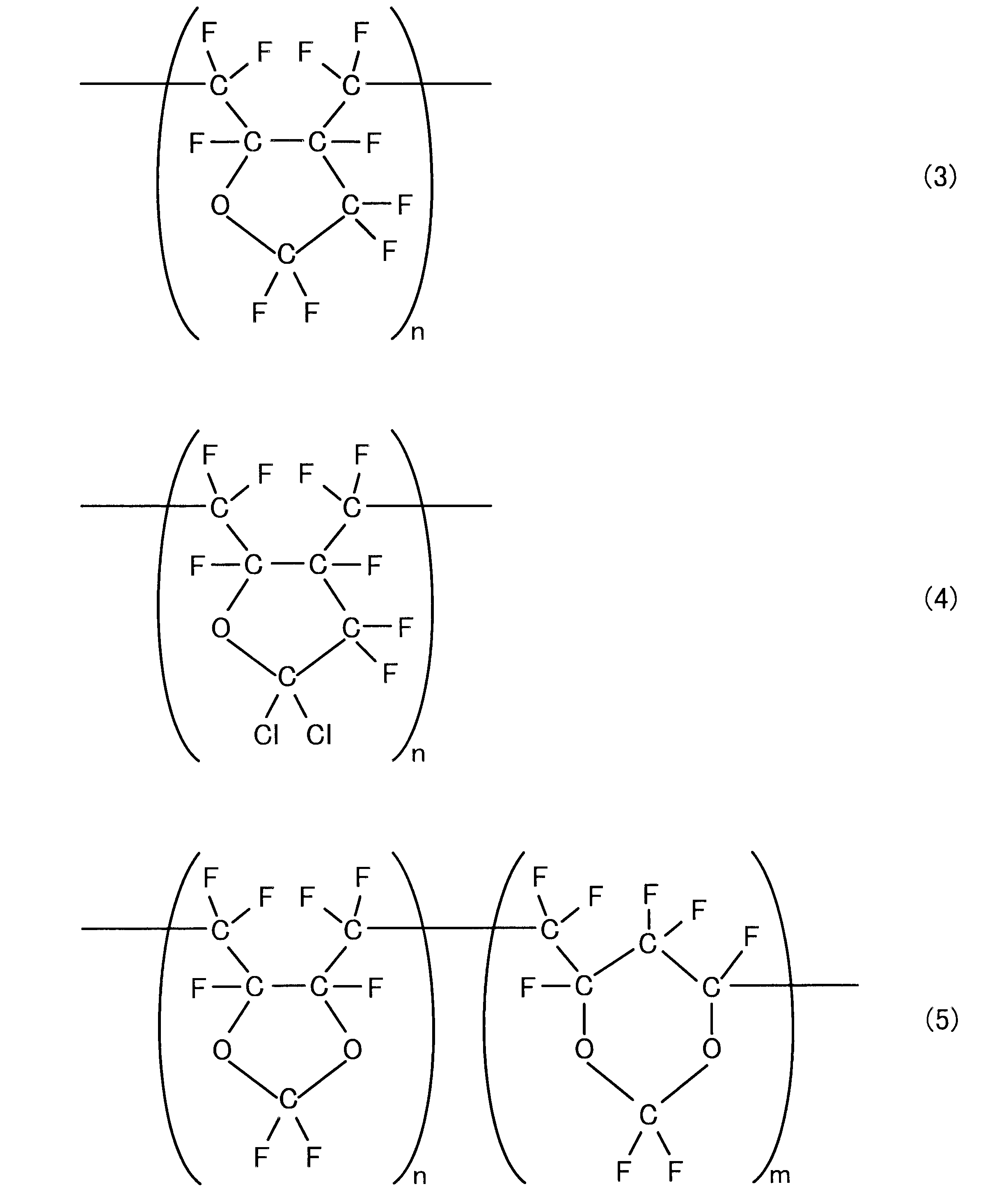
図6は、本実施の形態における可動アークコンタクト5の縦断面図、図7は、本実施の形態における可動アークコンタクト5の正面図である。図6は、図7のA-A線による縦断面図である。なお、可動アークコンタクト5の構成を除けば、本実施の形態のその他の構成は実施の形態1と同じである。すなわち、ガス遮断器1の構成は、図1または図5に示される構成と同じである。以下では、図1および図5も参照しながら説明する。
Claims (7)
- 棒状の固定アークコンタクトと、
前記固定アークコンタクトと接触または開離する円筒状の可動アークコンタクトと、
前記固定アークコンタクトと前記可動アークコンタクトとの間に発生するアークに吹付けられる消弧性ガスが蓄えられるパッファ室と、
前記固定アークコンタクトおよび前記可動アークコンタクトの一方の先端部に形成された収納穴に収納され、前記固定アークコンタクトおよび前記可動アークコンタクトの他方側の端面の少なくとも一部が前記先端部に形成された開口端を介して前記他方側に面し、前記他方側の端面が前記開口端よりも前記固定アークコンタクトおよび前記可動アークコンタクトの一方側に配置されるとともに、前記アークの熱により蒸発するアブレーション材料からなる絶縁材と、
を備えることを特徴とするガス遮断器。 - 前記絶縁材は、前記固定アークコンタクトの先端部に形成され可動アークコンタクト側に開口する収納穴に収納され、前記可動アークコンタクト側の端面が前記収納穴の開口端を介して前記可動アークコンタクト側に面するとともに、前記可動アークコンタクト側の端面が前記収納穴の開口端よりも前記収納穴の内側に配置されることを特徴とする請求項1に記載のガス遮断器。
- 前記固定アークコンタクトの先端部には、前記絶縁材を前記収納穴内に保持する保持部が前記絶縁材よりも前記可動アークコンタクト側に設けられることを特徴とする請求項2に記載のガス遮断器。
- 前記保持部は、前記可動アークコンタクト側からの平面視で円環状であり、かつ、滑らかで角のない縦断面形状であることを特徴とする請求項3に記載のガス遮断器。
- 前記可動アークコンタクトは、当該可動アークコンタクトの周方向に配列され当該可動アークコンタクトの軸方向に伸びる複数個のスリットにより分割されており、
前記絶縁材は、前記可動アークコンタクトの先端部に形成され固定アークコンタクト側と反対側に開口する収納穴に収納され、前記固定アークコンタクト側の端面の一部が前記スリットの前記固定アークコンタクト側の開口端を介して前記固定アークコンタクト側に面するとともに、前記固定アークコンタクト側の端面が前記開口端よりも前記固定アークコンタクト側と反対側に配置されることを特徴とする請求項1に記載のガス遮断器。 - 前記可動アークコンタクトの内周面には、円筒状のガイドが設けられており、
前記ガイドは、前記絶縁材を前記収納穴内に保持することを特徴とする請求項5に記載のガス遮断器。 - 前記アブレーション材料は、化学構造に、水素原子が含まれず、かつ、主鎖または環状構造に炭素-酸素結合が含まれる材料であることを特徴とする請求項1から6のいずれか1項に記載のガス遮断器。
Priority Applications (5)
| Application Number | Priority Date | Filing Date | Title |
|---|---|---|---|
| CN201580071709.3A CN107112162B (zh) | 2015-01-07 | 2015-01-07 | 气体断路器 |
| US15/538,117 US10115548B2 (en) | 2015-01-07 | 2015-01-07 | Gas circuit breaker |
| EP15876840.8A EP3244434B1 (en) | 2015-01-07 | 2015-01-07 | Gas circuit breaker |
| PCT/JP2015/050275 WO2016110962A1 (ja) | 2015-01-07 | 2015-01-07 | ガス遮断器 |
| JP2015532200A JP5921778B1 (ja) | 2015-01-07 | 2015-01-07 | ガス遮断器 |
Applications Claiming Priority (1)
| Application Number | Priority Date | Filing Date | Title |
|---|---|---|---|
| PCT/JP2015/050275 WO2016110962A1 (ja) | 2015-01-07 | 2015-01-07 | ガス遮断器 |
Publications (1)
| Publication Number | Publication Date |
|---|---|
| WO2016110962A1 true WO2016110962A1 (ja) | 2016-07-14 |
Family
ID=56015168
Family Applications (1)
| Application Number | Title | Priority Date | Filing Date |
|---|---|---|---|
| PCT/JP2015/050275 Ceased WO2016110962A1 (ja) | 2015-01-07 | 2015-01-07 | ガス遮断器 |
Country Status (5)
| Country | Link |
|---|---|
| US (1) | US10115548B2 (ja) |
| EP (1) | EP3244434B1 (ja) |
| JP (1) | JP5921778B1 (ja) |
| CN (1) | CN107112162B (ja) |
| WO (1) | WO2016110962A1 (ja) |
Families Citing this family (3)
| Publication number | Priority date | Publication date | Assignee | Title |
|---|---|---|---|---|
| CN111834054A (zh) * | 2019-04-16 | 2020-10-27 | 段小嬿 | 半封闭式双反冲灭弧绝缘子 |
| JP7221460B1 (ja) * | 2021-04-28 | 2023-02-13 | 三菱電機株式会社 | 開閉装置 |
| CN114864331B (zh) * | 2022-06-16 | 2025-11-28 | 西安西电开关电气有限公司 | 一种自能灭弧室 |
Citations (2)
| Publication number | Priority date | Publication date | Assignee | Title |
|---|---|---|---|---|
| JPS497084Y1 (ja) * | 1968-11-22 | 1974-02-19 | ||
| JP2014071973A (ja) * | 2012-09-28 | 2014-04-21 | Nippon Tungsten Co Ltd | 遮断器用コンタクト |
Family Cites Families (17)
| Publication number | Priority date | Publication date | Assignee | Title |
|---|---|---|---|---|
| US3946183A (en) * | 1974-04-05 | 1976-03-23 | Westinghouse Electric Corporation | Puffer piston gas blast circuit interrupter with insulating nozzle member |
| US4276456A (en) * | 1978-10-23 | 1981-06-30 | Westinghouse Electric Corp. | Double-flow puffer-type compressed-gas circuit-interrupter |
| DE3440212A1 (de) * | 1984-10-10 | 1986-04-17 | BBC Aktiengesellschaft Brown, Boveri & Cie., Baden, Aargau | Druckgasschalter |
| JPH069425Y2 (ja) | 1986-12-01 | 1994-03-09 | 日新電機株式会社 | ガス遮断器 |
| JPS63192637U (ja) * | 1987-05-29 | 1988-12-12 | ||
| JPS63198145U (ja) * | 1987-06-11 | 1988-12-20 | ||
| FR2628259A1 (fr) * | 1988-03-01 | 1989-09-08 | Merlin Gerin | Disjoncteur electrique a autosoufflage par pistonnage ou expansion de gaz isolant |
| FR2679375A1 (fr) | 1991-07-19 | 1993-01-22 | Alsthom Gec | Contact pour disjoncteur. |
| DE59303093D1 (de) * | 1992-02-06 | 1996-08-08 | Gec Alsthom T & D Ag | Druckgasschalter |
| JPH07320613A (ja) | 1994-05-20 | 1995-12-08 | Mitsubishi Electric Corp | 開閉器 |
| JPH08264085A (ja) | 1995-03-24 | 1996-10-11 | Toshiba Corp | パッファ形ガス遮断器 |
| DE19648633A1 (de) * | 1996-11-25 | 1998-05-28 | Asea Brown Boveri | Elektrisches Schaltgerät |
| JP2002298711A (ja) | 2001-01-29 | 2002-10-11 | Fuji Electric Co Ltd | ガス遮断器 |
| JP2003297196A (ja) | 2002-03-29 | 2003-10-17 | Toshiba Corp | 開閉器 |
| JP2009054481A (ja) | 2007-08-28 | 2009-03-12 | Mitsubishi Electric Corp | ガス遮断器 |
| JP2011054369A (ja) | 2009-09-01 | 2011-03-17 | Toshiba Corp | アーク電極、ガス絶縁開閉装置 |
| WO2013118348A1 (ja) | 2012-02-06 | 2013-08-15 | 三菱電機株式会社 | ガス遮断器 |
-
2015
- 2015-01-07 EP EP15876840.8A patent/EP3244434B1/en active Active
- 2015-01-07 WO PCT/JP2015/050275 patent/WO2016110962A1/ja not_active Ceased
- 2015-01-07 CN CN201580071709.3A patent/CN107112162B/zh not_active Expired - Fee Related
- 2015-01-07 JP JP2015532200A patent/JP5921778B1/ja active Active
- 2015-01-07 US US15/538,117 patent/US10115548B2/en active Active
Patent Citations (2)
| Publication number | Priority date | Publication date | Assignee | Title |
|---|---|---|---|---|
| JPS497084Y1 (ja) * | 1968-11-22 | 1974-02-19 | ||
| JP2014071973A (ja) * | 2012-09-28 | 2014-04-21 | Nippon Tungsten Co Ltd | 遮断器用コンタクト |
Also Published As
| Publication number | Publication date |
|---|---|
| JP5921778B1 (ja) | 2016-05-24 |
| US10115548B2 (en) | 2018-10-30 |
| EP3244434B1 (en) | 2019-09-04 |
| CN107112162A (zh) | 2017-08-29 |
| US20180012716A1 (en) | 2018-01-11 |
| EP3244434A1 (en) | 2017-11-15 |
| JPWO2016110962A1 (ja) | 2017-04-27 |
| EP3244434A4 (en) | 2018-08-22 |
| CN107112162B (zh) | 2019-04-12 |
Similar Documents
| Publication | Publication Date | Title |
|---|---|---|
| US9058947B2 (en) | Puffer-type gas circuit-breaker | |
| US9165732B2 (en) | Gas circuit breaker | |
| MX2012013125A (es) | Disyuntor de gas comprimido. | |
| JP5921778B1 (ja) | ガス遮断器 | |
| CN104335315B (zh) | 气体断路器 | |
| JP6270441B2 (ja) | ガス遮断器 | |
| JPH02172121A (ja) | 高圧遮断器 | |
| KR101455324B1 (ko) | 가스 차단기 | |
| WO2013179456A1 (ja) | ガス遮断器 | |
| US20150294818A1 (en) | Gas-insulated circuit breaker | |
| WO2018066119A1 (ja) | ガス遮断器 | |
| JP4879366B1 (ja) | ガス遮断器 | |
| US10665399B2 (en) | Gas circuit breaker | |
| KR101619303B1 (ko) | 가스 절연 차단기 | |
| RU2503078C1 (ru) | Элегазовый выключатель | |
| RU135446U1 (ru) | Баковый выключатель высокого напряжения с вакуумной дугогасительной камерой | |
| JP6084506B2 (ja) | ガス遮断器用の摺動部材及びこれを用いたガス遮断器 | |
| JP7200084B2 (ja) | ガス遮断器 | |
| JPWO2019092864A1 (ja) | ガス遮断器 | |
| JP2015023006A (ja) | ガス遮断器 | |
| JP6172344B1 (ja) | ガス絶縁開閉装置 | |
| CN111433878B (zh) | 气体断路器 | |
| JP6492665B2 (ja) | 真空遮断器及び真空遮断器の開閉構造 | |
| JP2023115499A (ja) | ガス遮断器 | |
| JPH0883545A (ja) | ガス開閉器 |
Legal Events
| Date | Code | Title | Description |
|---|---|---|---|
| ENP | Entry into the national phase |
Ref document number: 2015532200 Country of ref document: JP Kind code of ref document: A |
|
| 121 | Ep: the epo has been informed by wipo that ep was designated in this application |
Ref document number: 15876840 Country of ref document: EP Kind code of ref document: A1 |
|
| REEP | Request for entry into the european phase |
Ref document number: 2015876840 Country of ref document: EP |
|
| WWE | Wipo information: entry into national phase |
Ref document number: 15538117 Country of ref document: US |
|
| NENP | Non-entry into the national phase |
Ref country code: DE |