WO2016110992A1 - Transducteur électroacoustique - Google Patents
Transducteur électroacoustique Download PDFInfo
- Publication number
- WO2016110992A1 WO2016110992A1 PCT/JP2015/050433 JP2015050433W WO2016110992A1 WO 2016110992 A1 WO2016110992 A1 WO 2016110992A1 JP 2015050433 W JP2015050433 W JP 2015050433W WO 2016110992 A1 WO2016110992 A1 WO 2016110992A1
- Authority
- WO
- WIPO (PCT)
- Prior art keywords
- vibrating body
- valley
- belt
- conversion
- voice coil
- Prior art date
- Legal status (The legal status is an assumption and is not a legal conclusion. Google has not performed a legal analysis and makes no representation as to the accuracy of the status listed.)
- Ceased
Links
Images


Classifications
-
- H—ELECTRICITY
- H04—ELECTRIC COMMUNICATION TECHNIQUE
- H04R—LOUDSPEAKERS, MICROPHONES, GRAMOPHONE PICK-UPS OR LIKE ACOUSTIC ELECTROMECHANICAL TRANSDUCERS; ELECTRIC HEARING AIDS; PUBLIC ADDRESS SYSTEMS
- H04R7/00—Diaphragms for electromechanical transducers; Cones
- H04R7/02—Diaphragms for electromechanical transducers; Cones characterised by the construction
- H04R7/12—Non-planar diaphragms or cones
-
- H—ELECTRICITY
- H04—ELECTRIC COMMUNICATION TECHNIQUE
- H04R—LOUDSPEAKERS, MICROPHONES, GRAMOPHONE PICK-UPS OR LIKE ACOUSTIC ELECTROMECHANICAL TRANSDUCERS; ELECTRIC HEARING AIDS; PUBLIC ADDRESS SYSTEMS
- H04R9/00—Transducers of moving-coil, moving-strip, or moving-wire type
- H04R9/02—Details
- H04R9/04—Construction, mounting, or centering of coil
Definitions
- the present invention relates to an electroacoustic transducer suitable for a speaker that reproduces sound by vibrating a vertically split cylindrical surface or a microphone that collects sound.
- the Riffel type speaker has a diaphragm composed of a pair of rectangular curved plates, has good directivity in the mid-high range, and the sound spreads in the lateral direction along the curved direction of the diaphragm, and is almost spread in the vertical direction. It has the characteristic of not.
- Patent Document 1 a conductor pattern as a voice coil is printed on the center portion of the polymer resin film, and the center portion is folded and bonded to form a plate-like portion having a conductor pattern;
- a vibration plate is formed integrally with the curved first and second vibration parts, and a flat plate-like portion of the vibration plate is disposed in a magnetic gap in the magnetic circuit, and the tips of both vibration parts Discloses a speaker having a structure fixed to a support member.
- Patent Document 2 the center portion of the diaphragm is folded back with a concave portion, and a flat voice coil wound in an oval shape is disposed in the concave portion, and the voice coil is separated vertically.
- a speaker having a structure arranged in two magnetic gaps is disclosed. Also in this speaker, the outer peripheral part of the diaphragm is fixed on an annular frame.
- Patent Document 3 discloses a speaker having a structure in which a conductor is sandwiched between valleys of a diaphragm having a substantially V-shaped cross section and the conductor is installed in a magnetic field.
- Patent Document 4 discloses a speaker having a structure in which a bent portion of a bent diaphragm is directly coupled to a piezoelectric element.
- the speaker described in Patent Document 4 has a structure in which a bending portion at the center of the diaphragm is coupled to a piezoelectric element, and a general-purpose piezoelectric element can be used as an actuator.
- the length of the diaphragm and the diameter of the piezoelectric element are made substantially the same as shown in FIG.
- a flat portion having a predetermined width is formed in the bent portion of the diaphragm, and the back surface of the flat portion is bonded to the surface of the piezoelectric element. For this reason, there exists a possibility that an acoustic characteristic may be impaired by this flat part.
- the present invention has been made in view of such circumstances, and without damaging the shape of the vibration body having a pair of curved vibration surfaces, the vibration body and the conversion section such as a voice coil motor are firmly connected.
- An object is to provide a connected inexpensive electroacoustic transducer.
- a pair of vertically split cylindrical surfaces are formed in parallel, and a vibrating body in which a trough is formed between one side portions of the adjacent vertically split cylindrical surfaces;
- a transducer that converts vibration along the depth direction of the valley of the vibrating body and an electrical signal corresponding to the vibration, and the valley of the vibrating body includes the pair of vertically split cylindrical surfaces Are formed through joint portions that are joined to each other, and at the bottom portion of the valley portion, a band-like portion whose width direction is the depth direction of the valley portion is provided along the extending direction of the valley portion.
- the conversion portion is connected to a position in the length direction of the strip portion, and the connection portion between the conversion portion and the strip portion is formed to extend in the width direction of the strip portion.
- the connecting portion between the converting portion and the vibrating body is formed to extend in the width direction of the belt-like portion of the vibrating body, the area of the connecting portion can be increased, and the vibrating body and the drive can be driven.
- the conversion part can be firmly connected, and vibration can be reliably transmitted between the vibrating body and the conversion part.
- a general-purpose voice coil motor or the like can be applied as the conversion unit and can be manufactured at low cost. In this case, since the conversion unit is connected to the bottom of the valley of the vibrating body, the shape of the vertically split cylindrical surface and the valley of the vibrating body is not impaired, and excellent acoustic characteristics can be maintained.
- the conversion unit is formed with a flat part along the surface direction of the band-like part, and the connection part is fixed by overlapping the band-like part and the flat part. It is good to have. By setting it as such a structure, the connection area of a conversion part and a vibrating body can be enlarged, and it can connect more firmly.
- the conversion portion is provided with a groove portion along the extending direction of the belt-like portion, and the connection portion is fixed by engaging the belt-like portion with the groove portion. It is good to have.
- the connection portions are arranged on both sides of the band-like portion of the vibrating body, and the conversion portion and the vibrating body can be firmly connected.
- the band-shaped portion is integrally provided with a cap capable of fitting a portion of the conversion portion, and the connection portion includes a portion of the conversion portion on the cap. It is good to fit and fix.
- the connecting portion between the vibrating body and the conversion portion is formed to extend in the width direction of the belt-like portion of the vibrating body, so that the vibrating body and the conversion portion are firmly connected. Vibration can be reliably transmitted between them, and a general-purpose voice coil or the like can be applied as the conversion unit, which can be manufactured at low cost.
- FIG. 4 is a half-sectional perspective view of the speaker cut along line AA in FIG. 3.
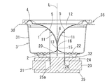
- FIG. 4 is a cross-sectional view taken along line AA in FIG. 3.
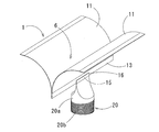
- FIG. 6 is a perspective view of the vicinity of a connection portion between a vibrating body and one actuator. It is a longitudinal cross-sectional view which shows a vibrating body. It is a perspective view explaining the other modification of a voice coil. It is a perspective view explaining the further another modification of a voice coil.
- FIG. 10 is an exploded perspective view of FIG. 9. It is a perspective view explaining the further another modification of a vibrating body.
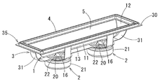
- the speaker (electroacoustic transducer) of this embodiment includes a vibrating body 1, an actuator (converting unit) 2 that reciprocates the vibrating body 1, and a support frame 3 that supports the vibrating body 1 and the actuator 2. And an edge portion 4 for supporting the vibrating body 1 on the support frame 3 so as to be reciprocally movable.
- the vertical direction is set so that the side on which the edge portion 4 is provided is up and the side on which the actuator 2 is provided is down, and the support is formed in a rectangular shape as will be described later.
- the long side direction of the frame 3 is a vertical direction or a length direction
- the short side direction is a horizontal direction
- the upper surface is the front surface
- the lower surface is the back surface
- the vertical direction (length direction) is called the x direction
- the horizontal direction is called the y direction
- the vertical direction is called the z direction. It shall be.
- the vibrating body 1 has a surface shape in which a pair of vertically-divided cylindrical surfaces 5 are formed in parallel and a valley portion 6 is formed between one side portions of adjacent vertically-divided cylindrical surfaces 5. .
- the vibrating body 1 in the illustrated example includes a pair of curved plates 11 that are curved along the vertically split cylindrical surface 5, and a connecting plate 12 that connects these curved plates 11. Sides forming the valley 6 are joined together.
- the connecting plate 12 is provided at both ends of the valley portion 6 so as to block the entire valley portion 6.
- the extending direction of the valley portion 6 is a vertical direction or a length direction, and a direction perpendicular to the vertical direction is a horizontal direction.
- the material of the vibrating body 1 is not limited, and a synthetic resin, paper, metal, or the like generally used as a diaphragm for a speaker can be used.
- a synthetic resin such as polypropylene or polyester can be used.
- the film made of can be formed relatively easily by vacuum forming.
- the vertically-divided cylindrical surface 5 of the curved plate 11 does not necessarily have to be a single circular arc surface, and a cross-section along a circumferential direction (lateral direction) of the vertically-divided cylindrical surface 5 in which a plurality of curvatures are continuous.
- Can be used such as a parabola shape or a spline curve whose curvature changes constant or continuously, a rectangular cylindrical surface, a stepped shape having a plurality of steps, etc. It is curved in the circumferential direction (lateral direction) of the vertically divided cylindrical surface 5, and is linear in a direction perpendicular to the one direction (vertical direction of the vertically divided cylindrical surface 5).
- the pair of curved plates 11 are arranged in parallel so that the convex direction faces the same surface side, and adjacent side portions are joined with the tangential direction in common. Therefore, the trough 6 is formed between the curved plates 11 in a straight line along the longitudinal direction of the vertically split cylindrical surface 5.
- the joint part of both the curved plates 11 is a band-shaped portion 13, and this band-shaped portion 13 is formed by, for example, as shown in FIGS.
- An actuator 2 to be described later is connected to a position (preferably a central position) in the middle of the length direction of the strip 13 (the vertical direction of the vertically split cylindrical surface 5). Further, in order to obtain a uniform sound source, it is preferable to form both curved plates 11 symmetrically with respect to the tangent L of the valley 6 as shown in FIGS.
- a voice coil motor is used as the actuator 2, and the actuator 2 includes a voice coil 20 joined to a midway position in the length direction of the strip 13 of the curved plate 11 and a magnet mechanism 21 fixed to the support frame 3. .
- two actuators 2 are provided at intervals in the length direction of the band-like portion 13 of the curved plate 11.
- the voice coil 20 is obtained by winding a coil 20b around a cylindrical bobbin 20a. In this case, as shown in FIG. 6 and the like, the coil 20b is wound except for the upper end portion of the bobbin 20a, and the upper end portion of the bobbin 20a projects above the coil 20b and is crushed in the radial direction.
- the flat part 15 is formed in the upper end part of the bobbin 20a along the axial direction and the diameter direction. Then, the flat portion 15 is superimposed on one side surface of the belt-like portion 13 of the curved plate 11 and fixed with an adhesive or the like, so that the connection portion 16 between the vibrating body 1 and the voice coil 20 is formed. Yes.
- the connecting portion 16 extends in the width direction and the length direction of the strip portion 13 and is formed with a large area.
- the outer periphery of the voice coil 20 is supported by the support frame 3 via the damper 22, and the voice coil 20 can reciprocate along the axial direction of the voice coil 20 with respect to the support frame 3.
- the damper 22 is made of a material used for a general dynamic speaker.
- the magnet mechanism 21 includes an annular magnet 23, a ring-shaped outer yoke 24 fixed to one pole of the magnet 23, and an inner yoke 25 fixed to the other pole.
- an annular magnetic gap 26 is formed between the outer yoke 24 and the inner yoke 25, and a voice coil is formed in the magnetic gap 26.
- 20 end portions are arranged in an inserted state.
- the support frame 3 is formed of, for example, a metal material, and in the illustrated example, a flange portion 30 formed in a rectangular frame shape, a plurality of arm portions 31 extending below the flange portion 30, and lower ends of these arm portions 31. And a pair of formed annular frames 32 (the number of actuators 2). And the vibrating body 1 is arrange
- the edge portion 4 is formed in a rectangular frame shape corresponding to the outer peripheral portion of the vibrating body 1.
- the edge portion 4 can also be made of a material used for a general dynamic speaker.
- the support frame 3 and the edge portion 4 constitute a support portion 35 that supports the vibrating body 1 so as to vibrate in the depth direction (z direction) of the trough portion 6.
- the directivity of sound in the lateral direction along the circumferential direction of the vertically split cylindrical surface 5 is similar to the diaphragm used in the Riffel type speaker. It is wide and narrow in the vertical direction. Further, like the Riffel type speaker, it has a wide directivity in the mid-high range.
- a belt-like portion 13 is provided at the bottom of the valley portion 6 of the vibrating body 1 along the extending direction of the valley portion 6, and the voice 16 is connected to the voice coil 20 of the actuator 1 at the connection portion 16.
- the flat portion 15 at the upper end of the coil 20 is overlapped and fixed (fixed) on the side surface of the belt-like portion 13 of the vibrating body 1. In this way, the vibrating body 1 and the voice coil 20 of the actuator 2 are fixed so that the connecting portion between the strip 13 of the vibrating body 1 and the flat portion 15 of the voice coil 20 is fixed over a wide area.
- the actuator 2 that is used for a normal dynamic speaker can be applied, and the actuator 2 can be manufactured at low cost.
- both the vertically-divided cylindrical surfaces 5 are formed in a shape having a common tangent L in the valley portion 6, and the actuator reciprocates along the same direction as the tangent L in the valley portion 6. 2 are connected. For this reason, the reciprocating motion of the actuator 2 can be efficiently applied to the end of the curved plate 11, and the curved plate 11 can be driven with a fast response speed and less loss during transmission.
- both ends of the valley portion 6 are in an open state, a part of the sound wave radiated by the diaphragm 1 passes through the opened space to the back side of the curved plate 11, but the connecting plate 12. Since both ends of the valley portion 6 are blocked by the above, it is possible to prevent sound waves from coming off to the back side of the curved plate 11 and efficiently emit sound from the entire front surface of the vibrator 1. .
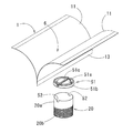
- a concave groove portion 41 is provided in the diameter direction of the voice coil 20 along the extending direction of the belt-like portion 13 of the vibrator 1, and the belt-like portion 13 of the vibrator 1 is engaged and fixed to the concave groove portion 41. ing.
- the outer surface of the belt-like portion 13 of the vibrating body 1 and the inner surface of the concave groove portion 41 are bonded to form the connection portion 42, whereby the connection portion 42 is formed extending in the width direction of the belt-like portion 3. Is done. Since the belt-like portion 13 is fitted into the groove portion 41, compared to the case where the belt-like portion 13 is simply placed on and joined to the opening of the cylindrical voice coil, only the depth of the groove portion 41 is obtained. The vibrating body 1 and the voice coil 20 can be firmly connected.
- the voice coil 20 of the actuator is provided with a dust cap 51 that closes the opening at the upper end of the voice coil 20, and the vibrating body 1 is fixed to the dust cap 51.
- the dust cap 51 has a circular top plate portion 51a and a peripheral wall portion 51b formed on the outer periphery thereof, and a concave groove portion 51c is provided so as to cross the upper surface of the top plate portion 51a in the diameter direction.
- the band-like portion 13 of the vibrating body 1 is engaged with and fixed to the concave groove portion 51c.
- a concave portion 51 c protrudes downward to form a protrusion (not shown), and the upper end of the voice coil 20 is engaged with the protrusion of the dust cap 51.
- the notch 52 is formed.
- the notch 52 is not necessarily required.
- the belt-like portion 13 of the vibrating body 1 is engaged in the concave groove portion 51c of the dust cap 51, and the outer surface of the belt-like portion 13 of the vibrating body 1 and the inner surface of the concave groove portion 51c are bonded to each other. 53 is formed, and therefore the connecting portion 53 is formed to extend in the width direction of the belt-like portion 13.
- the connecting portion 53 with the belt-like portion 13 is not only in the width direction of the belt-like portion 13 but also in the length direction (top plate portion). 51a in the diameter direction).
- the belt-like portion 13 of the vibrating body 1 can be firmly connected to the dust cap 51 by a surface, and the dust cap 51 itself can also be firmly connected to the upper end portion of the voice coil 20 by a surface. Therefore, the driving force of the actuator can be accurately and reliably transmitted to the vibrating body 1.
- the belt-like portion 13 has a central portion in the length direction.
- a cap 55 that can be fitted to the upper end portion (joining portion) of the voice coil 20 is integrally formed.
- the cap 55 is deformed into a semicircular shape so as to expand in the lateral direction (y direction) without joining the central portion of one side portion of the curved plate 11, and the top plate portion 55a and the peripheral wall portion 55b. And is formed so that the diametrical direction coincides with the length direction of the belt-like portion 13.
- the voice coil 20 is used in a cylindrical shape as indicated by a two-dot chain line, and the upper end portion of the voice coil 20 is fitted and bonded to the cap 55.
- the inner peripheral surface of the peripheral wall portion 55b of the cap 55 and the voice A connection portion 56 is formed in which the outer peripheral surface of the upper end portion of the coil 20 is bonded in a surface contact state.
- the actuator and the vibrating body 1 can be firmly connected by the surfaces along the width direction and the length direction of the belt-like portion 13, and the driving force of the actuator can be accurately and reliably transmitted to the vibrating body 1. can do.
- the vibrating body in the first embodiment is configured by a curved plate and a connecting plate
- the connecting plate is not necessarily required.
- the curved plates may not be connected entirely, and only the upper end portion, the lower end portion or the intermediate portion in the height direction may be connected.
- the two curved plates are formed symmetrically with respect to the center of the valley (tangent line L).
- the curved plates are not necessarily line-symmetric.
- the vibrating body is supported on the support frame by the edge portion so as to be reciprocally movable.
- the vibrating body includes one having no edge portion.
- the edge portion When the edge portion is not provided, the side portion opposite to the joint portion of both curved plates is fixed to the support frame in a state where the connecting plate is eliminated.
- the side of the curved plate should be fixed in a state of being sandwiched by a flexible material instead of a rigid body, and such a fixed structure ensures that the vibration of the curved plate is reflected by the fixed part. Can be reduced.
- the voice coil motor is applied as the conversion unit that reciprocally drives the vibrating body, a piezoelectric element or the like may be used instead of the voice coil motor. Further, in the above-described embodiment, as illustrated in FIG.
- the conversion units are provided at two positions with an interval in the length direction (x direction) of the band-shaped unit of the vibrator, but the number of conversion units is limited to two. Instead, one or three or more may be arranged at the center in the length direction (x direction) of the band-shaped portion of the vibrating body or at intervals in the length direction of the band-shaped portion. Moreover, you may reinforce a strip
- a conversion unit such as a voice coil motor converts an electric signal based on a sound signal into vibration of a vibrating body.
- a voice coil is used as the conversion unit.
- a motor or the like can be used, and the conversion unit in that case converts the vibration of the vibrating body that receives a sound wave to vibrate into an electric signal.
- the vertically split cylindrical surface is the vibration surface, and the vibration body and the conversion unit are firmly connected, so that the vibration is transmitted reliably and the sensitivity is maintained.
- directivity is improved, and sound can be collected with a wide directivity over a wide frequency band from a low sound range to a high sound range.
Landscapes
- Engineering & Computer Science (AREA)
- Physics & Mathematics (AREA)
- Acoustics & Sound (AREA)
- Signal Processing (AREA)
- Multimedia (AREA)
- Audible-Bandwidth Dynamoelectric Transducers Other Than Pickups (AREA)
Abstract
L'invention concerne un transducteur électroacoustique à faible coût dans lequel, sans endommager la forme d'un corps vibrant comprenant une paire de surfaces vibrantes incurvées, le corps vibrant est fermement raccordé à une unité de conversion comme un moteur de bobine mobile par exemple. Un transducteur électroacoustique comprend : un corps vibrant 1 dans lequel une paire de surfaces cylindriques divisées longitudinalement 5 sont formées en parallèle, et une vallée 6 est formée entre des sections latérales respectives des surfaces cylindriques divisées longitudinalement 5, les sections latérales étant adjacentes ; et un actionneur 2 qui entraîne le corps vibrant 1 en va-et-vient le long de la direction dans le sens de la profondeur de la vallée 6. La vallée 6 du corps vibrant 1 est formée via une partie de jonction où la paire de surfaces cylindriques divisées longitudinalement 5 sont réunies l'une à l'autre. Une partie en forme de ceinture 13, dont la direction dans le sens de la largeur est définie comme la direction dans le sens de la profondeur de la vallée 6, est prévue sur la base de la vallée 6 le long de la direction dans le sens de l'extension de la vallée 6. L'actionneur 2 est raccordé à une position qui est à mi-chemin le long de la direction dans le sens de la longueur de la partie en forme de ceinture 13, et une partie de connexion qui raccorde l'actionneur à la partie en forme de courroie est formée de sorte à s'étendre dans le sens de la largeur de la partie en forme de ceinture 13.
Priority Applications (1)
| Application Number | Priority Date | Filing Date | Title |
|---|---|---|---|
| PCT/JP2015/050433 WO2016110992A1 (fr) | 2015-01-09 | 2015-01-09 | Transducteur électroacoustique |
Applications Claiming Priority (1)
| Application Number | Priority Date | Filing Date | Title |
|---|---|---|---|
| PCT/JP2015/050433 WO2016110992A1 (fr) | 2015-01-09 | 2015-01-09 | Transducteur électroacoustique |
Publications (1)
| Publication Number | Publication Date |
|---|---|
| WO2016110992A1 true WO2016110992A1 (fr) | 2016-07-14 |
Family
ID=56355713
Family Applications (1)
| Application Number | Title | Priority Date | Filing Date |
|---|---|---|---|
| PCT/JP2015/050433 Ceased WO2016110992A1 (fr) | 2015-01-09 | 2015-01-09 | Transducteur électroacoustique |
Country Status (1)
| Country | Link |
|---|---|
| WO (1) | WO2016110992A1 (fr) |
Citations (10)
| Publication number | Priority date | Publication date | Assignee | Title |
|---|---|---|---|---|
| JPS55144489U (fr) * | 1979-04-03 | 1980-10-16 | ||
| JPS5721200A (en) * | 1980-07-11 | 1982-02-03 | Shigeya Nishihara | Moving coil type speaker |
| JPS5843091U (ja) * | 1981-09-17 | 1983-03-23 | 澤藤 正 | 電気音響変換器用振動板 |
| JPH02283199A (ja) * | 1989-04-24 | 1990-11-20 | Minebea Co Ltd | ハイアスペクト・スピーカ |
| JPH08102988A (ja) * | 1994-09-29 | 1996-04-16 | Foster Electric Co Ltd | スピーカ |
| JPH10191494A (ja) * | 1996-10-30 | 1998-07-21 | Matsushita Electric Ind Co Ltd | スピーカ |
| JPH1127792A (ja) * | 1997-07-07 | 1999-01-29 | Foster Electric Co Ltd | スピーカ用振動板の製造方法 |
| JP2001054191A (ja) * | 1999-08-05 | 2001-02-23 | Matsushita Electric Ind Co Ltd | スピーカ |
| JP2002078079A (ja) * | 2000-08-24 | 2002-03-15 | Pioneer Electronic Corp | 電気音響変換器 |
| JP2009159248A (ja) * | 2007-12-26 | 2009-07-16 | Yukihiro Ando | スピーカー |
-
2015
- 2015-01-09 WO PCT/JP2015/050433 patent/WO2016110992A1/fr not_active Ceased
Patent Citations (10)
| Publication number | Priority date | Publication date | Assignee | Title |
|---|---|---|---|---|
| JPS55144489U (fr) * | 1979-04-03 | 1980-10-16 | ||
| JPS5721200A (en) * | 1980-07-11 | 1982-02-03 | Shigeya Nishihara | Moving coil type speaker |
| JPS5843091U (ja) * | 1981-09-17 | 1983-03-23 | 澤藤 正 | 電気音響変換器用振動板 |
| JPH02283199A (ja) * | 1989-04-24 | 1990-11-20 | Minebea Co Ltd | ハイアスペクト・スピーカ |
| JPH08102988A (ja) * | 1994-09-29 | 1996-04-16 | Foster Electric Co Ltd | スピーカ |
| JPH10191494A (ja) * | 1996-10-30 | 1998-07-21 | Matsushita Electric Ind Co Ltd | スピーカ |
| JPH1127792A (ja) * | 1997-07-07 | 1999-01-29 | Foster Electric Co Ltd | スピーカ用振動板の製造方法 |
| JP2001054191A (ja) * | 1999-08-05 | 2001-02-23 | Matsushita Electric Ind Co Ltd | スピーカ |
| JP2002078079A (ja) * | 2000-08-24 | 2002-03-15 | Pioneer Electronic Corp | 電気音響変換器 |
| JP2009159248A (ja) * | 2007-12-26 | 2009-07-16 | Yukihiro Ando | スピーカー |
Similar Documents
| Publication | Publication Date | Title |
|---|---|---|
| JP6123838B2 (ja) | 電気音響変換器 | |
| JP6048469B2 (ja) | 電気音響変換器 | |
| EP3145214A1 (fr) | Transducteur électroacoustique | |
| JP6048470B2 (ja) | 電気音響変換器 | |
| US10142736B2 (en) | Electroacoustic transducer | |
| JP6065819B2 (ja) | 電気音響変換器 | |
| WO2019102860A1 (fr) | Diaphragme et transducteur électroacoustique comprenant ce diaphragme | |
| JP6065820B2 (ja) | 電気音響変換器 | |
| JP6187666B2 (ja) | 電気音響変換器 | |
| WO2016110992A1 (fr) | Transducteur électroacoustique | |
| WO2016110991A1 (fr) | Transducteur électroacoustique | |
| JP2016082321A (ja) | 電気音響変換器 | |
| WO2017154328A1 (fr) | Transducteur électro-acoustique | |
| JP2017169006A (ja) | 電気音響変換器 | |
| WO2016052022A1 (fr) | Transducteur électroacoustique |
Legal Events
| Date | Code | Title | Description |
|---|---|---|---|
| 121 | Ep: the epo has been informed by wipo that ep was designated in this application |
Ref document number: 15876869 Country of ref document: EP Kind code of ref document: A1 |
|
| NENP | Non-entry into the national phase |
Ref country code: DE |
|
| NENP | Non-entry into the national phase |
Ref country code: JP |
|
| 122 | Ep: pct application non-entry in european phase |
Ref document number: 15876869 Country of ref document: EP Kind code of ref document: A1 |