WO2016113898A1 - 冷却システム用減圧装置及び冷却システム - Google Patents
冷却システム用減圧装置及び冷却システム Download PDFInfo
- Publication number
- WO2016113898A1 WO2016113898A1 PCT/JP2015/051064 JP2015051064W WO2016113898A1 WO 2016113898 A1 WO2016113898 A1 WO 2016113898A1 JP 2015051064 W JP2015051064 W JP 2015051064W WO 2016113898 A1 WO2016113898 A1 WO 2016113898A1
- Authority
- WO
- WIPO (PCT)
- Prior art keywords
- refrigerant
- cooling system
- fine bubble
- bubble forming
- decompression device
- Prior art date
- Legal status (The legal status is an assumption and is not a legal conclusion. Google has not performed a legal analysis and makes no representation as to the accuracy of the status listed.)
- Ceased
Links
Images




Classifications
-
- F—MECHANICAL ENGINEERING; LIGHTING; HEATING; WEAPONS; BLASTING
- F25—REFRIGERATION OR COOLING; COMBINED HEATING AND REFRIGERATION SYSTEMS; HEAT PUMP SYSTEMS; MANUFACTURE OR STORAGE OF ICE; LIQUEFACTION SOLIDIFICATION OF GASES
- F25B—REFRIGERATION MACHINES, PLANTS OR SYSTEMS; COMBINED HEATING AND REFRIGERATION SYSTEMS; HEAT PUMP SYSTEMS
- F25B41/00—Fluid-circulation arrangements
- F25B41/30—Expansion means; Dispositions thereof
- F25B41/31—Expansion valves
- F25B41/34—Expansion valves with the valve member being actuated by electric means, e.g. by piezoelectric actuators
-
- F—MECHANICAL ENGINEERING; LIGHTING; HEATING; WEAPONS; BLASTING
- F16—ENGINEERING ELEMENTS AND UNITS; GENERAL MEASURES FOR PRODUCING AND MAINTAINING EFFECTIVE FUNCTIONING OF MACHINES OR INSTALLATIONS; THERMAL INSULATION IN GENERAL
- F16K—VALVES; TAPS; COCKS; ACTUATING-FLOATS; DEVICES FOR VENTING OR AERATING
- F16K17/00—Safety valves; Equalising valves, e.g. pressure relief valves
- F16K17/20—Excess-flow valves
- F16K17/22—Excess-flow valves actuated by the difference of pressure between two places in the flow line
- F16K17/24—Excess-flow valves actuated by the difference of pressure between two places in the flow line acting directly on the cutting-off member
- F16K17/28—Excess-flow valves actuated by the difference of pressure between two places in the flow line acting directly on the cutting-off member operating in one direction only
-
- F—MECHANICAL ENGINEERING; LIGHTING; HEATING; WEAPONS; BLASTING
- F16—ENGINEERING ELEMENTS AND UNITS; GENERAL MEASURES FOR PRODUCING AND MAINTAINING EFFECTIVE FUNCTIONING OF MACHINES OR INSTALLATIONS; THERMAL INSULATION IN GENERAL
- F16K—VALVES; TAPS; COCKS; ACTUATING-FLOATS; DEVICES FOR VENTING OR AERATING
- F16K51/00—Other details not peculiar to particular types of valves or cut-off apparatus
-
- F—MECHANICAL ENGINEERING; LIGHTING; HEATING; WEAPONS; BLASTING
- F25—REFRIGERATION OR COOLING; COMBINED HEATING AND REFRIGERATION SYSTEMS; HEAT PUMP SYSTEMS; MANUFACTURE OR STORAGE OF ICE; LIQUEFACTION SOLIDIFICATION OF GASES
- F25B—REFRIGERATION MACHINES, PLANTS OR SYSTEMS; COMBINED HEATING AND REFRIGERATION SYSTEMS; HEAT PUMP SYSTEMS
- F25B41/00—Fluid-circulation arrangements
- F25B41/30—Expansion means; Dispositions thereof
- F25B41/31—Expansion valves
-
- F—MECHANICAL ENGINEERING; LIGHTING; HEATING; WEAPONS; BLASTING
- F25—REFRIGERATION OR COOLING; COMBINED HEATING AND REFRIGERATION SYSTEMS; HEAT PUMP SYSTEMS; MANUFACTURE OR STORAGE OF ICE; LIQUEFACTION SOLIDIFICATION OF GASES
- F25B—REFRIGERATION MACHINES, PLANTS OR SYSTEMS; COMBINED HEATING AND REFRIGERATION SYSTEMS; HEAT PUMP SYSTEMS
- F25B2500/00—Problems to be solved
- F25B2500/01—Geometry problems, e.g. for reducing size
-
- F—MECHANICAL ENGINEERING; LIGHTING; HEATING; WEAPONS; BLASTING
- F25—REFRIGERATION OR COOLING; COMBINED HEATING AND REFRIGERATION SYSTEMS; HEAT PUMP SYSTEMS; MANUFACTURE OR STORAGE OF ICE; LIQUEFACTION SOLIDIFICATION OF GASES
- F25B—REFRIGERATION MACHINES, PLANTS OR SYSTEMS; COMBINED HEATING AND REFRIGERATION SYSTEMS; HEAT PUMP SYSTEMS
- F25B2500/00—Problems to be solved
- F25B2500/05—Cost reduction
-
- F—MECHANICAL ENGINEERING; LIGHTING; HEATING; WEAPONS; BLASTING
- F25—REFRIGERATION OR COOLING; COMBINED HEATING AND REFRIGERATION SYSTEMS; HEAT PUMP SYSTEMS; MANUFACTURE OR STORAGE OF ICE; LIQUEFACTION SOLIDIFICATION OF GASES
- F25B—REFRIGERATION MACHINES, PLANTS OR SYSTEMS; COMBINED HEATING AND REFRIGERATION SYSTEMS; HEAT PUMP SYSTEMS
- F25B2500/00—Problems to be solved
- F25B2500/09—Improving heat transfers
-
- Y—GENERAL TAGGING OF NEW TECHNOLOGICAL DEVELOPMENTS; GENERAL TAGGING OF CROSS-SECTIONAL TECHNOLOGIES SPANNING OVER SEVERAL SECTIONS OF THE IPC; TECHNICAL SUBJECTS COVERED BY FORMER USPC CROSS-REFERENCE ART COLLECTIONS [XRACs] AND DIGESTS
- Y02—TECHNOLOGIES OR APPLICATIONS FOR MITIGATION OR ADAPTATION AGAINST CLIMATE CHANGE
- Y02B—CLIMATE CHANGE MITIGATION TECHNOLOGIES RELATED TO BUILDINGS, e.g. HOUSING, HOUSE APPLIANCES OR RELATED END-USER APPLICATIONS
- Y02B30/00—Energy efficient heating, ventilation or air conditioning [HVAC]
- Y02B30/70—Efficient control or regulation technologies, e.g. for control of refrigerant flow, motor or heating
Definitions
- the present invention relates to a decompression device for a cooling system and a cooling system.
- Patent Document 1 a refrigerant vaporized by removing heat of vaporization from an object to be cooled in a heat exchanger is liquefied in a compressor and a condenser and then reused through a pressure reducing valve.
- a heat exchanger of a cooling system for cooling a fluid As a heat exchanger of a cooling system for cooling a fluid, a first plate having a flow path through which a fluid to be cooled flows and a second plate having a flow path through which a refrigerant flows are alternately stacked. Laminated heat exchangers are known. Such a stacked heat exchanger has a large number of thin flow paths, and thus is small and has high heat exchange efficiency. However, if the refrigerant flowing into the narrow flow path of such a stacked heat exchanger is a gas-liquid mixed phase flow, it is difficult for the refrigerant to uniformly flow into each flow path, so that the heat exchange performance may be reduced. There is.
- a separator that separates the refrigerant that is in the gas-liquid mixed phase flow after the pressure reducing valve into a gas phase and a liquid phase is provided at the front stage of the heat exchanger. It is possible. However, the separator tends to be large because it includes a container for accommodating the refrigerant therein and separating it into a gas phase and a liquid phase. As described above, there is room for improvement in downsizing the cooling system using the heat exchanger with a thin refrigerant flow path. That is, the objective of this invention is providing the small cooling system with high heat exchange efficiency, and its decompression device.
- One aspect of the present invention is a pressure reducing valve disposed downstream of a refrigerant condenser, and a refrigerant bubble disposed in the refrigerant flow path from the condenser to the heat exchanger.
- a decompression device for a cooling system provided with a fine bubble forming part dispersed in the liquid phase of the refrigerant.
- the gas phase of the refrigerant that has become a gas-liquid mixed phase flow by the decompression device is dispersed in the liquid phase as fine bubbles in the liquid phase and flows into the heat exchanger. Heat exchange performance is high compared to the case of direct flow into the exchanger.
- the cooling system is downsized as compared with the case where the separator is provided in the front stage of the heat exchanger and the liquid phase of the refrigerant is separated. can do.
- the fine bubble forming portion has an opening in which a plurality of through-hole portions constituting a plurality of fine flow passages having a flow passage cross-sectional area smaller than a cross-sectional area of the flow passage is formed.
- the opening diameter of at least the discharge side of each through hole in the plurality of through hole portions may be 1 mm or less.
- each through hole in the plurality of through hole portions may have an elongated opening having a width of 1 mm or less.
- the fine bubble forming unit may be disposed inside the decompression valve. In this case, since the fine bubble forming portion is present inside the pressure reducing valve, the pressure reducing device is small.
- the cooling system decompression device may further include a horizontal pipe having a refrigerant flow path that connects the fine bubble forming section and the heat exchanger horizontally and linearly.
- the horizontal pipe delivers the refrigerant in which the fine bubbles are dispersed by passing through the fine bubble forming portion to the heat exchanger in a horizontal and linear manner, Liquid separation hardly occurs.
- Another aspect of the present invention includes a compressor that compresses a refrigerant, a condenser that is disposed on a rear stage side of the compressor and that liquefies at least a part of the refrigerant, and is disposed on a rear stage side of the condenser. It is a cooling system provided with the heat exchanger which has a flow path which flows, and the decompression device for cooling systems of the said aspect.
- the gas phase of the refrigerant that has become a gas-liquid mixed phase flow by the decompression device is dispersed in the liquid phase as fine bubbles in the liquid phase and flows into the heat exchanger. Heat exchange performance is high compared to the case of direct flow into the exchanger.
- the fine bubble forming portion is arranged inside the refrigerant flow path, a small cooling system compared with the case where the separator is provided in the front stage of the heat exchanger and the liquid phase of the refrigerant is separated. can do.
- FIG. 1 is a schematic diagram of the cooling system of the present embodiment.
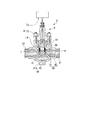
- FIG. 2 is a schematic diagram showing a pressure reducing valve of the cooling system.
- FIG. 3 is a schematic view showing a fine bubble forming part attached to a pressure reducing valve of the cooling system.
- FIG. 4 is a schematic diagram showing a heat exchanger of the cooling system.
- the cooling system 1 of this embodiment includes a compressor 2, a condenser 3, a decompression device 4, and a heat exchanger 14.
- the compressor 2 compresses the refrigerant 40 (see FIG. 2) vaporized in the heat exchanger 14 to be described later and sends it to the condenser 3.
- the configuration of the compressor 2 is not particularly limited.
- the condenser 3 liquefies the refrigerant 40 compressed by the compressor 2 and sends it to the decompression device 4.
- the configuration of the condenser 3 is not particularly limited.
- the decompression device 4 shown in FIG. 2 is a decompression device for a cooling system that decompresses the refrigerant 40 partially liquefied by the condenser 3 in the cooling system of the present embodiment. As shown in FIG. 2, the decompression device 4 includes a decompression valve 5 and a fine bubble forming unit 20.
- the pressure reducing valve 5 includes an inlet 6 connected to a pipe 31 connected to the condenser 3, an outlet 7 connected to a refrigerant pipe 32 connected to the heat exchanger 14, and a throttle unit 8.
- the throttle unit 8 includes a cylinder 9, a piston 12, and an operating device 13.
- the cylinder 9 includes a fine bubble forming portion 20 for allowing the refrigerant 40 to flow into the cylinder 9 from the inflow port 6, and an outflow opening portion 11 for allowing the refrigerant 40 to flow out from the cylinder 9 to the outflow port 7.
- the fine bubble forming portion 20 is formed by forming a plurality of through-hole portions 22 penetrating on the wall surface of the cylinder 9 by processing means such as electric discharge machining, laser machining, drilling, or three-dimensional modeling. .
- the through-hole portion 22 has a channel cross-sectional area smaller than the cross-sectional area of the inlet 6 (see FIG. 2) of the pressure reducing valve 5.
- the through hole portion 22 communicates the inside and outside of the cylinder 9 with the fine bubble forming portion 20 formed in the cylinder 9.
- the through hole portion 22 of the present embodiment has a circular opening end having an inner diameter of 1 mm or less on at least the discharge side of each through hole portion 22.
- the refrigerant 40 passing through the through-hole portion 22 becomes a gas-liquid mixed phase flow during the decompression process.
- the gas phase 41 of the refrigerant 40 is sheared at the opening end on the outflow side to be bubbled.
- the refrigerant 40 is finely divided from a gas-liquid mixed phase flow having a large bubble diameter generated in a decompression process in a conventional decompression device that does not have each through-hole portion 22 having a circular opening end having an inner diameter of 1 mm or less.
- the bubbles 41 a change to a state (bubble flow) dispersed in the liquid phase 42.
- the fine bubbles 41 a generated by the fine bubble forming unit 20 of the present embodiment are dispersed in the liquid phase 42 as fine bubbles less than millibubbles.
- a supercritical liquid of carbon dioxide in a supercritical state in a state where a difference of 20 atm or more is generated inside and outside the cylinder 9 is passed through the through hole of the fine bubble forming unit 20
- a bubble flow containing bubbles having an average bubble diameter of 0.2 mm can be generated.
- the piston 12 shown in FIG. 2 is a member that is advanced and retracted by the operating device 13 inside the cylinder 9.
- the piston 12 changes the opening degree of the through hole portion 22 by closing a part of the through hole portion 22 of the cylinder 9. A part or all of the through-hole portion 22 is blocked by the piston 12, whereby the flow rate of the refrigerant 40 changes.
- the operating device 13 adjusts the position of the piston 12 in the cylinder 9 so that the refrigerant 40 flowing out of the pressure reducing valve 5 from the outlet 7 has a predetermined constant flow rate.
- the heat exchanger 14 includes a first pipe line 16 that forms a flow path through which a fluid substance to be cooled flows, and a pipe line through which a refrigerant 40 (see FIG. 2) flows.
- a second pipe line 18 is provided.
- the heat exchanger 14 of the present embodiment includes a first plate 15 having a plurality of first pipelines 16 and a second plate 17 having a plurality of second pipelines 18. The first plate 15 and the second plate 17 are alternately stacked. In the present embodiment, heat exchange is performed between the first plate 15 and the second plate 17.
- the refrigerant flows into the decompression device 4 by the compressor 2 and the condenser 3 as a gas-liquid mixed phase flow or liquid phase at least partially liquefied.
- the refrigerant 40 that has flowed into the decompression device 4 flows from the inlet 6 into the cylinder 9 through the through-hole portion 22.
- coolant 40 which flows in into the cylinder 9 from the inflow port 6 is the through-hole part 22 of the fine bubble formation part 20 (refer FIG. 3). ).
- the gas phase portion of the refrigerant 40 that has become a gas-liquid two-phase flow during the decompression process when passing through the through-hole portion 22 is sheared at the opening end on the outflow side of the through-hole portion 22 and is finer than the millibubble shown in FIG. Air bubbles 41a are formed.
- the refrigerant 40 after passing through the fine bubble forming unit 20 is in a state where the fine bubbles 41 a are dispersed in the liquid phase 42 of the refrigerant 40.
- the refrigerant 40 in which the fine bubbles 41a are dispersed is sent to the heat exchanger 14 shown in FIG. 1 while the fine bubbles 41a are maintained as the bubbles.
- heat exchanger 14 In the heat exchanger 14 shown in FIGS. 1 and 4, heat exchange is performed between the material to be cooled and the refrigerant 40. That is, heat is transferred from the first pipe line 16 constituting the flow path through which the substance to be cooled flows to the refrigerant 40 in the second pipe line 18. The refrigerant 40 is heated and vaporized by the heat transmitted from the first pipe line 16, thereby removing heat from the substance to be cooled by the vaporization heat of the refrigerant 40, and then exiting the heat exchanger 14 and passing through the pipe 33. Return to the compressor 2 (see FIG. 1).
- the refrigerant 40 flowing into the second pipe 18 has a fine bubble 41a in the gas phase of the refrigerant 40. For this reason, the fine bubbles 41 a are distributed substantially uniformly throughout the second pipeline 18 inside the second pipeline 18. As a result, since the vaporization of the refrigerant 40 occurs in the entire area in the second pipe 18, the heat exchange efficiency is higher than when only the gas phase of the refrigerant 40 enters a part of the second pipe 18. .
- the fine bubble forming unit 20 does not separate the gas phase 41 from the two-phase mixed phase flow of the refrigerant 40, and the gas phase of the refrigerant 40
- the fine bubbles 41 a of 41 can be dispersed in the liquid phase 42 and sent to the heat exchanger 14. For this reason, only the liquid phase 42 of the refrigerant 40 is obtained without providing a container-like separator having a certain volume for separating the refrigerant 40 into the gas phase 41 and the liquid phase 42 and collecting only the liquid phase 42.
- a heat exchange efficiency equivalent to that when flowing into the heat exchanger 14 can be obtained.
- the fine bubble forming unit 20 is disposed inside the flow path of the refrigerant 40 from the condenser 3 to the heat exchanger 14, particularly in the present embodiment, inside the pressure reducing valve 5. It is possible to make the decompression device 4 smaller than the case of providing the above. For this reason, the cooling system 1 as a whole can be downsized.
- FIG. 5 is a schematic diagram of the cooling system of the present embodiment.
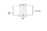
- FIG. 6 is a schematic view showing a fine bubble forming unit attached to the refrigerant pipe of the cooling system.
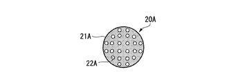
- FIG. 7 is a schematic diagram showing an example of the shape of the through-hole portion in the fine bubble forming portion.
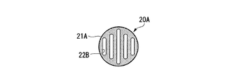
- FIG. 8 is a schematic diagram showing another example of the shape of the through hole portion in the fine bubble forming portion.
- a cooling system 1A of the present embodiment shown in FIG. 5 includes a decompression device 4A having a configuration different from that of the decompression device 4 disclosed in the first embodiment, instead of the decompression device 4 disclosed in the first embodiment.
- the decompression device 4A of the present embodiment includes a decompression valve 5A and a fine bubble forming unit 20A.
- a known configuration can be appropriately selected and used as the pressure reducing valve 5A.
- the fine bubble forming portion 20 ⁇ / b> A has an opening area larger than the cross-sectional area of the plate-like frame body portion 21 ⁇ / b> A having a shape corresponding to the cross-sectional shape of the refrigerant pipe 32 and the refrigerant pipe 32. Is formed of an opening member provided with a plurality of small through-hole portions 22A.
- the through-hole portion 22A is a flow path that connects the upstream side and the downstream side of the fine bubble forming portion 20A in the refrigerant pipe 32 in a state where the fine bubble forming portion 20A is attached to the refrigerant pipe 32.
- the opening shape of the through-hole portion 22A in the fine bubble forming portion 20A of the present embodiment may not be a circular opening.
- an elongated slit 22B having a width of 1 mm or less may be formed in the frame body portion 21A.
- the shape of the through-hole portion 22A is not particularly limited as long as it is a pressure loss body that configures a flow path gap of 1 mm or less in the refrigerant pipe 32.
- the fine bubble forming part 20A of the decompression device 4A of the cooling system 1A shown in FIG. 5 is arranged in a part of the refrigerant pipe 32.
- the refrigerant pipe 32 is divided into an upstream portion 32-1 and a downstream portion 32-2 so as to sandwich the fine bubble forming portion 20A therebetween. Fixed in a sandwiched state.
- the refrigerant 40 flowing through the refrigerant pipe 32 through the pressure reducing valve 5A shown in FIG. 5 remains in a state in which a part of the refrigerant 40 is liquefied in the condenser 3 until reaching the fine bubble forming unit 20A. It is a liquid mixed phase flow or a liquid phase flow. As the gas-liquid mixed phase flow or liquid phase flow passes through the plurality of through-hole portions 22A of the fine bubble forming portion 20A and depressurizes, the gas phase 41 of the refrigerant 40 becomes the fine bubbles 41a as in the first embodiment. Dispersed in the liquid phase 42 of the refrigerant 40.
- the known pressure reducing valve 5 can be appropriately selected and adopted, the production of the cooling system 1A is easy, and the degree of freedom in designing the cooling system 1A is high.
- FIG. 9 is a schematic diagram of the cooling system of the present embodiment.
- the decompression device 4 disclosed in the second embodiment includes a horizontal pipe 32A that connects the fine bubble forming unit 20A and the heat exchanger 14 horizontally and linearly.
- the configuration differs from the second embodiment.
- the pipe downstream of the fine bubble forming portion 20A is a straight tube.
- the cooling system 1B of the present embodiment is installed such that the center line of the horizontal pipe 32A is horizontal when the cooling system 1B is installed.
- Inside the horizontal pipe 32A which is a straight pipe extending horizontally, is a refrigerant flow path through which the refrigerant 40 flows along with the fine bubbles 41a. Since the refrigerant 40 is unlikely to stay inside the horizontal pipe 32A, the refrigerant 40 is prevented from staying and the fine bubbles 41a are prevented from growing. For this reason, it can prevent that a bubble diameter becomes large and the refrigerant
- the refrigerant pipe 32-1 upstream from the fine bubble forming unit 20A may not be a straight pipe extending horizontally.
- the refrigerant pipe 32-1 upstream from the fine bubble forming portion 20A is not a straight pipe, the refrigerant 40 tends to stay in a bent portion of the refrigerant pipe 32-1. If the gas phase 41 of the refrigerant 40 stays in the portion where the refrigerant 40 stays, a part of the stayed gas phase 41 may become a large bubble and move toward the horizontal pipe 32A.
- the bubbles are made into the fine bubbles 41a by the fine bubble forming part 20A, large bubbles are prevented from flowing directly into the heat exchanger 14.
- the degree of freedom in handling the refrigerant pipe 32-1 is high.
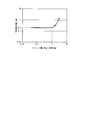
- FIG. 10 is a graph showing the relationship between the configuration of the fine bubble forming portion and the average bubble diameter of the fine bubbles.
- the inner diameter of the through hole portion of the fine bubble forming portion is 0.2 mm, 0.4 mm, 1.0 mm, and 1.8 mm (see FIG. 7)
- the through hole portion of the fine bubble forming portion Is a slit having a width of 0.2 mm, 0.4 mm, 1.0 mm, and 1.8 mm (see FIG. 8)
- the gas of carbon dioxide after passing through the through-hole portions of these fine bubble forming portions.
- the average bubble diameter of bubbles in a liquid two-phase flow is shown.
- the average bubble diameter in the through-hole part of the fine bubble forming part is 0.2 mm, 0.4 mm, and 1.0 mm
- the average bubble diameter is 0.2 mm, which is less than the millibubble. Fine bubbles are generated.
- the hole diameter or slit width in the through hole portion of the fine bubble forming portion is 1.8 mm
- the average bubble diameter cannot be measured, and no fine bubbles are generated after passing through the through hole portion.
- the hole diameter or slit width in the through-hole part of the fine bubble forming part exceeds 1 mm, the average bubble diameter increases rapidly, and it is considered difficult to uniformly disperse as bubbles in the liquid phase.
- the present invention can be used for a cooling system using a refrigeration cycle, a gas pressure raising system, and the like.
- Cooling system 2 Compressor 3 Condenser 4, 4A Pressure reducing device 5, 5A Pressure reducing valve 6 Inlet 7 Outlet 8 Throttle part 9 Cylinder 11 Outlet opening 12 Piston 13 Actuator 14 Heat exchanger 15 1st Plate 16 First pipe line 17 Second plate 18 Second pipe line 20, 20A Fine bubble forming part 21A Frame part 22, 22A Through hole part 22B Slit (through hole part, elongated opening) 31 piping 32 refrigerant piping 32-1 upstream portion of refrigerant piping 32-2 downstream portion of refrigerant piping 32A horizontal piping 33 piping 40 refrigerant 41 refrigerant gas phase 41a refrigerant fine bubbles 42 refrigerant liquid phase
Landscapes
- Engineering & Computer Science (AREA)
- General Engineering & Computer Science (AREA)
- Mechanical Engineering (AREA)
- Physics & Mathematics (AREA)
- Thermal Sciences (AREA)
- Cooling Or The Like Of Semiconductors Or Solid State Devices (AREA)
- Heat-Exchange Devices With Radiators And Conduit Assemblies (AREA)
- Separation By Low-Temperature Treatments (AREA)
Abstract
Description
すなわち、本発明の目的は、熱交換効率の高い小型の冷却システム及びその減圧装置を提供することである。
この発明によれば、減圧装置によって気液混相流となった冷媒の気相を微細気泡形成部が微細な気泡として液相に分散させて熱交換器に流入させるので、気液混相流が熱交換器に直接流入する場合と比較して熱交換性能が高い。さらにこの発明によれば、微細気泡形成部は冷媒の流路内部に配されるので、セパレータを熱交換器の前段に設けて冷媒の液相を分離する場合と比較して冷却システムを小型化することができる。
この場合、複数の貫通孔部を気液混相流が通過する過程で気相が微細気泡となるので、簡素な構成とすることができる。
上記態様の冷却システム用減圧装置において、前記複数の貫通孔部における各貫通孔は、幅が1mm以下をなす細長開口を有していてもよい。
これらの場合、冷媒中の気泡が微細気泡となり、冷媒中の微細気泡が熱交換器に流入するまでの間に微細気泡が成長しにくくなるので、熱交換器の各流路に冷媒が均等に流入しやすくなり、熱交換性能が低下しにくい。
この場合、減圧弁の内部に微細気泡形成部があるので減圧装置が小型である。
この場合、微細気泡形成部を通過することで微細気泡が分散された状態となっている冷媒を、水平配管が、水平且つ直線状に熱交換器まで送液するので、微細気泡の成長や気液分離が起こりにくい。
この発明によれば、減圧装置によって気液混相流となった冷媒の気相を微細気泡形成部が微細な気泡として液相に分散させて熱交換器に流入させるので、気液混相流が熱交換器に直接流入する場合と比較して熱交換性能が高い。さらにこの発明によれば、微細気泡形成部は冷媒の流路内部に配されるので、セパレータを熱交換器の前段に設けて冷媒の液相を分離する場合と比較して小型の冷却システムとすることができる。
本発明の第1実施形態について説明する。図1は、本実施形態の冷却システムの模式図である。図2は、冷却システムの減圧弁を示す模式図である。図3は、冷却システムの減圧弁に取り付けられた微細気泡形成部を示す模式図である。図4は、冷却システムの熱交換器を示す模式図である。
本実施形態の熱交換器14は、複数の第一管路16を有する第一プレート15と、複数の第二管路18を有する第二プレート17とを備えている。第一プレート15と第二プレート17とは、交互に積層されている。本実施形態では、第一プレート15と第二プレート17との間で熱交換が行われる。
図1に示す本実施形態の冷却システム1の動作時には、圧縮機2及び凝縮器3によって、冷媒は少なくとも一部が液化された気液混相流又は液相となって減圧装置4に流入する。
図2に示すように、減圧装置4内に流入した冷媒40は、流入口6からシリンダ9内へと、貫通孔部22を通じて流入する。本実施形態では貫通孔部22が微細気泡形成部20として形成されているので、流入口6からシリンダ9内へと流入する冷媒40は、微細気泡形成部20の貫通孔部22(図3参照)を通過することとなる。貫通孔部22を通過する際の減圧過程で気液2相流となった冷媒40の気相部分は、貫通孔部22の流出側の開口端において剪断されて図2に示すミリバブル未満の微細気泡41aとなる。
本発明の第2実施形態について説明する。なお、以下に説明する各実施形態において、第1実施形態に開示された構成要素と同等の構成要素には第1実施形態と同一の符号が付され、重複する説明及び図示が省略されている。
本実施形態の減圧装置4Aは、減圧弁5Aと、微細気泡形成部20Aとを備えている。
図6及び図7に示すように、微細気泡形成部20Aは、冷媒用配管32の断面形状に対応した形状をなす板状の枠体部21Aと、冷媒用配管32の断面積よりも開口面積が小さな複数の貫通孔部22Aと、を備えた開口部材からなる。
また、本実施形態の微細気泡形成部20Aにおける貫通孔部22Aの開口形状は、円形の開口でなくてもよい。たとえば、他の構成例として、図8に示すように、幅が1mm以下となる細長のスリット22Bが枠体部21Aに形成されていてもよい。また、貫通孔部22Aは、1mm以下の流路隙間を冷媒用配管32内に構成する圧損体であればその形状は特に限定されない。
図5に示す冷却システム1Aの減圧装置4Aの微細気泡形成部20Aは、冷媒用配管32の一部に配される。たとえば、冷媒用配管32は、図6に示すように、微細気泡形成部20Aを間に挟むように上流部分32-1と下流部分32-2とに分割されており、微細気泡形成部20Aを挟み込んだ状態で固定される。
本発明の第3実施形態について説明する。図9は、本実施形態の冷却システムの模式図である。
本実施例では、微細気泡形成部の貫通孔部の内径が0.2mm、0.4mm、1.0mm、及び1.8mmである場合(図7参照)、及び微細気泡形成部の貫通孔部が、幅0.2mm、0.4mm、1.0mm、及び1.8mmのスリットである場合(図8参照)について、これらの微細気泡形成部の貫通孔部を通過した後の二酸化炭素の気液2相流における気泡の平均気泡径を示す。
2 圧縮機
3 凝縮器
4,4A 減圧装置
5,5A 減圧弁
6 流入口
7 流出口
8 絞り部
9 シリンダ
11 流出開口部
12 ピストン
13 操作器
14 熱交換器
15 第一プレート
16 第一管路
17 第二プレート
18 第二管路
20,20A 微細気泡形成部
21A 枠体部
22,22A 貫通孔部
22B スリット(貫通孔部,細長開口)
31 配管
32 冷媒用配管
32-1 冷媒用配管の上流部分
32-2 冷媒用配管の下流部分
32A 水平配管
33 配管
40 冷媒
41 冷媒の気相
41a 冷媒の微細気泡
42 冷媒の液相
Claims (7)
- 冷媒の凝縮器の後段に配された減圧弁と、
前記凝縮器から熱交換器に至るまでの前記冷媒の流路の内部に配され前記冷媒の気相を微細気泡として前記冷媒の液相に分散させる微細気泡形成部と、
を備えた冷却システム用減圧装置。 - 前記微細気泡形成部は、前記流路の断面積よりも小さな流路断面積を有する複数の微細流路を構成する複数の貫通孔部が形成された開口部材を有する
請求項1に記載の冷却システム用減圧装置。 - 前記複数の貫通孔部における各貫通孔の少なくとも排出側の開口径が1mm以下である
請求項2に記載の冷却システム用減圧装置。 - 前記複数の貫通孔部における各貫通孔は、幅が1mm以下をなす細長開口を有する
請求項2に記載の冷却システム用減圧装置。 - 前記微細気泡形成部が前記減圧弁の内部に配されている
請求項1に記載の冷却システム用減圧装置。 - 前記微細気泡形成部と前記熱交換器とを水平且つ直線状に接続する冷媒流路を有する水平配管をさらに備える
請求項1に記載の冷却システム用減圧装置。 - 冷媒を圧縮する圧縮機と、
前記圧縮機の後段側に配され前記冷媒の少なくとも一部を液化させる凝縮器と、
前記凝縮器の後段側に配され前記冷媒が流れる流路を有する熱交換器と、
請求項1から請求項6のいずれか一項に記載の冷却システム用減圧装置と、
を備えた冷却システム。
Priority Applications (4)
| Application Number | Priority Date | Filing Date | Title |
|---|---|---|---|
| US15/538,874 US20170350631A1 (en) | 2015-01-16 | 2015-01-16 | Pressure reducing device for cooling system and cooling system |
| JP2016569193A JP6592803B2 (ja) | 2015-01-16 | 2015-01-16 | 冷却システム用減圧装置及び冷却システム |
| EP15877850.6A EP3222936B1 (en) | 2015-01-16 | 2015-01-16 | Cooling system |
| PCT/JP2015/051064 WO2016113898A1 (ja) | 2015-01-16 | 2015-01-16 | 冷却システム用減圧装置及び冷却システム |
Applications Claiming Priority (1)
| Application Number | Priority Date | Filing Date | Title |
|---|---|---|---|
| PCT/JP2015/051064 WO2016113898A1 (ja) | 2015-01-16 | 2015-01-16 | 冷却システム用減圧装置及び冷却システム |
Publications (1)
| Publication Number | Publication Date |
|---|---|
| WO2016113898A1 true WO2016113898A1 (ja) | 2016-07-21 |
Family
ID=56405459
Family Applications (1)
| Application Number | Title | Priority Date | Filing Date |
|---|---|---|---|
| PCT/JP2015/051064 Ceased WO2016113898A1 (ja) | 2015-01-16 | 2015-01-16 | 冷却システム用減圧装置及び冷却システム |
Country Status (4)
| Country | Link |
|---|---|
| US (1) | US20170350631A1 (ja) |
| EP (1) | EP3222936B1 (ja) |
| JP (1) | JP6592803B2 (ja) |
| WO (1) | WO2016113898A1 (ja) |
Cited By (1)
| Publication number | Priority date | Publication date | Assignee | Title |
|---|---|---|---|---|
| CN108720775A (zh) * | 2017-04-13 | 2018-11-02 | 东芝生活电器株式会社 | 餐具清洗机 |
Families Citing this family (1)
| Publication number | Priority date | Publication date | Assignee | Title |
|---|---|---|---|---|
| JP6615153B2 (ja) * | 2017-06-16 | 2019-12-04 | 東京エレクトロン株式会社 | 基板処理装置、基板載置機構、および基板処理方法 |
Citations (6)
| Publication number | Priority date | Publication date | Assignee | Title |
|---|---|---|---|---|
| JPH07146032A (ja) * | 1993-11-26 | 1995-06-06 | Matsushita Seiko Co Ltd | 膨張弁 |
| JP2003314929A (ja) * | 2002-04-19 | 2003-11-06 | Daikin Ind Ltd | 空気調和機 |
| JP2007132601A (ja) * | 2005-11-10 | 2007-05-31 | Furukawa Electric Co Ltd:The | エアコン用室外機 |
| JP2007162851A (ja) * | 2005-12-14 | 2007-06-28 | Fuji Koki Corp | 電動弁 |
| JP2008180476A (ja) * | 2007-01-26 | 2008-08-07 | Fuji Koki Corp | 膨張弁 |
| JP2011002140A (ja) * | 2009-06-18 | 2011-01-06 | Tgk Co Ltd | 膨張弁 |
Family Cites Families (8)
| Publication number | Priority date | Publication date | Assignee | Title |
|---|---|---|---|---|
| JPH11325655A (ja) * | 1998-05-14 | 1999-11-26 | Matsushita Seiko Co Ltd | 消音器および空気調和機 |
| ES2347761T3 (es) * | 2001-01-31 | 2010-11-04 | Mitsubishi Denki Kabushiki Kaisha | Dispositivo de estrangulacion. |
| US6510700B1 (en) * | 2001-08-17 | 2003-01-28 | Visteon Global Technologies, Inc. | Electrical expansion valve |
| JP2006098020A (ja) * | 2004-09-30 | 2006-04-13 | Mitsubishi Heavy Ind Ltd | 空気調和機およびストレーナー |
| JP2006336992A (ja) * | 2005-06-06 | 2006-12-14 | Matsushita Electric Ind Co Ltd | 空気調和機 |
| JP4193910B2 (ja) * | 2006-06-29 | 2008-12-10 | ダイキン工業株式会社 | 冷媒分流器一体化構造の膨張弁 |
| WO2015063854A1 (ja) * | 2013-10-29 | 2015-05-07 | 三菱電機株式会社 | 膨張弁 |
| CN106461092B (zh) * | 2014-07-02 | 2018-12-28 | 三菱电机株式会社 | 膨胀阀及制冷循环装置 |
-
2015
- 2015-01-16 US US15/538,874 patent/US20170350631A1/en not_active Abandoned
- 2015-01-16 JP JP2016569193A patent/JP6592803B2/ja active Active
- 2015-01-16 EP EP15877850.6A patent/EP3222936B1/en active Active
- 2015-01-16 WO PCT/JP2015/051064 patent/WO2016113898A1/ja not_active Ceased
Patent Citations (6)
| Publication number | Priority date | Publication date | Assignee | Title |
|---|---|---|---|---|
| JPH07146032A (ja) * | 1993-11-26 | 1995-06-06 | Matsushita Seiko Co Ltd | 膨張弁 |
| JP2003314929A (ja) * | 2002-04-19 | 2003-11-06 | Daikin Ind Ltd | 空気調和機 |
| JP2007132601A (ja) * | 2005-11-10 | 2007-05-31 | Furukawa Electric Co Ltd:The | エアコン用室外機 |
| JP2007162851A (ja) * | 2005-12-14 | 2007-06-28 | Fuji Koki Corp | 電動弁 |
| JP2008180476A (ja) * | 2007-01-26 | 2008-08-07 | Fuji Koki Corp | 膨張弁 |
| JP2011002140A (ja) * | 2009-06-18 | 2011-01-06 | Tgk Co Ltd | 膨張弁 |
Cited By (1)
| Publication number | Priority date | Publication date | Assignee | Title |
|---|---|---|---|---|
| CN108720775A (zh) * | 2017-04-13 | 2018-11-02 | 东芝生活电器株式会社 | 餐具清洗机 |
Also Published As
| Publication number | Publication date |
|---|---|
| EP3222936B1 (en) | 2020-03-11 |
| EP3222936A1 (en) | 2017-09-27 |
| EP3222936A4 (en) | 2017-12-20 |
| JP6592803B2 (ja) | 2019-10-23 |
| JPWO2016113898A1 (ja) | 2017-09-07 |
| US20170350631A1 (en) | 2017-12-07 |
Similar Documents
| Publication | Publication Date | Title |
|---|---|---|
| AU2005326650B2 (en) | Liquid-vapor separator for a minichannel heat exchanger | |
| KR101462176B1 (ko) | 열교환기 | |
| US8171987B2 (en) | Minichannel heat exchanger header insert for distribution | |
| KR20170074991A (ko) | 적층형 헤더, 열교환기, 및, 공기 조화 장치 | |
| CN105074358B (zh) | 调节hvac系统的膨胀装置的容量 | |
| US20160177829A1 (en) | Microchannel heat exchangers for gas turbine intercooling and condensing | |
| EP2578967A2 (en) | Pressure Correcting Distributor for Heating and Cooling Systems | |
| WO2017022239A1 (ja) | 熱交換装置 | |
| JPWO2016038830A1 (ja) | 熱交換装置 | |
| ITRM20070520A1 (it) | Impianto frigorifero a co2 con compressore a viti ad immersione in olio con disposizione a due stadi | |
| CN104634007B (zh) | 一种漏液装置及具有气液分离功能的换热器 | |
| JP5452367B2 (ja) | 気液分離器および冷凍サイクル装置 | |
| US20180034119A1 (en) | Cooling Device for Stored Energy Sources | |
| CN106949681B (zh) | 用于润滑剂管理的吸入管流量控制 | |
| CN114748941A (zh) | 压缩机系统分离器罐挡板和用于压缩机系统的分离装置 | |
| CN106461092A (zh) | 膨胀阀及制冷循环装置 | |
| JP6325992B2 (ja) | 絞り装置及び冷凍サイクルシステム | |
| JP6592803B2 (ja) | 冷却システム用減圧装置及び冷却システム | |
| CN104364598A (zh) | 制冷剂回路用热交换器 | |
| DE112013005970T5 (de) | Ejektor | |
| US20150020534A1 (en) | Method for recycling energy from compressor outlet, and air conditioner | |
| JP3195404U (ja) | 冷媒凝縮器 | |
| JP2005037054A (ja) | 冷媒サイクル装置用熱交換器 | |
| JP2016138677A (ja) | 冷凍サイクル装置 | |
| JP2018013248A5 (ja) |
Legal Events
| Date | Code | Title | Description |
|---|---|---|---|
| 121 | Ep: the epo has been informed by wipo that ep was designated in this application |
Ref document number: 15877850 Country of ref document: EP Kind code of ref document: A1 |
|
| ENP | Entry into the national phase |
Ref document number: 2016569193 Country of ref document: JP Kind code of ref document: A |
|
| REEP | Request for entry into the european phase |
Ref document number: 2015877850 Country of ref document: EP |
|
| WWE | Wipo information: entry into national phase |
Ref document number: 15538874 Country of ref document: US |
|
| NENP | Non-entry into the national phase |
Ref country code: DE |