WO2016114058A1 - 機械部品の製造方法、機械部品の製造装置、回転対称面の加工方法、記録媒体およびプログラム - Google Patents
機械部品の製造方法、機械部品の製造装置、回転対称面の加工方法、記録媒体およびプログラム Download PDFInfo
- Publication number
- WO2016114058A1 WO2016114058A1 PCT/JP2015/085197 JP2015085197W WO2016114058A1 WO 2016114058 A1 WO2016114058 A1 WO 2016114058A1 JP 2015085197 W JP2015085197 W JP 2015085197W WO 2016114058 A1 WO2016114058 A1 WO 2016114058A1
- Authority
- WO
- WIPO (PCT)
- Prior art keywords
- axis
- cutting edge
- rotationally symmetric
- symmetric surface
- cutting
- Prior art date
- Legal status (The legal status is an assumption and is not a legal conclusion. Google has not performed a legal analysis and makes no representation as to the accuracy of the status listed.)
- Ceased
Links
Images

















Classifications
-
- B—PERFORMING OPERATIONS; TRANSPORTING
- B23—MACHINE TOOLS; METAL-WORKING NOT OTHERWISE PROVIDED FOR
- B23B—TURNING; BORING
- B23B1/00—Methods for turning or working essentially requiring the use of turning-machines; Use of auxiliary equipment in connection with such methods
-
- G—PHYSICS
- G05—CONTROLLING; REGULATING
- G05B—CONTROL OR REGULATING SYSTEMS IN GENERAL; FUNCTIONAL ELEMENTS OF SUCH SYSTEMS; MONITORING OR TESTING ARRANGEMENTS FOR SUCH SYSTEMS OR ELEMENTS
- G05B19/00—Program-control systems
- G05B19/02—Program-control systems electric
- G05B19/18—Numerical control [NC], i.e. automatically operating machines, in particular machine tools, e.g. in a manufacturing environment, so as to execute positioning, movement or co-ordinated operations by means of program data in numerical form
- G05B19/4093—Numerical control [NC], i.e. automatically operating machines, in particular machine tools, e.g. in a manufacturing environment, so as to execute positioning, movement or co-ordinated operations by means of program data in numerical form characterised by part programming, e.g. entry of geometrical information as taken from a technical drawing, combining this with machining and material information to obtain control information, named part program, for the NC machine
-
- B—PERFORMING OPERATIONS; TRANSPORTING
- B23—MACHINE TOOLS; METAL-WORKING NOT OTHERWISE PROVIDED FOR
- B23B—TURNING; BORING
- B23B5/00—Turning-machines or devices specially adapted for particular work; Accessories specially adapted therefor
- B23B5/36—Turning-machines or devices specially adapted for particular work; Accessories specially adapted therefor for turning specially-shaped surfaces by making use of relative movement of the tool and work produced by geometrical mechanisms, i.e. forming-lathes
- B23B5/38—Turning-machines or devices specially adapted for particular work; Accessories specially adapted therefor for turning specially-shaped surfaces by making use of relative movement of the tool and work produced by geometrical mechanisms, i.e. forming-lathes for turning conical surfaces inside or outside, e.g. taper pins
-
- G—PHYSICS
- G05—CONTROLLING; REGULATING
- G05B—CONTROL OR REGULATING SYSTEMS IN GENERAL; FUNCTIONAL ELEMENTS OF SUCH SYSTEMS; MONITORING OR TESTING ARRANGEMENTS FOR SUCH SYSTEMS OR ELEMENTS
- G05B19/00—Program-control systems
- G05B19/02—Program-control systems electric
- G05B19/18—Numerical control [NC], i.e. automatically operating machines, in particular machine tools, e.g. in a manufacturing environment, so as to execute positioning, movement or co-ordinated operations by means of program data in numerical form
- G05B19/4093—Numerical control [NC], i.e. automatically operating machines, in particular machine tools, e.g. in a manufacturing environment, so as to execute positioning, movement or co-ordinated operations by means of program data in numerical form characterised by part programming, e.g. entry of geometrical information as taken from a technical drawing, combining this with machining and material information to obtain control information, named part program, for the NC machine
- G05B19/40937—Numerical control [NC], i.e. automatically operating machines, in particular machine tools, e.g. in a manufacturing environment, so as to execute positioning, movement or co-ordinated operations by means of program data in numerical form characterised by part programming, e.g. entry of geometrical information as taken from a technical drawing, combining this with machining and material information to obtain control information, named part program, for the NC machine concerning programming of machining or material parameters, pocket machining
-
- G—PHYSICS
- G05—CONTROLLING; REGULATING
- G05B—CONTROL OR REGULATING SYSTEMS IN GENERAL; FUNCTIONAL ELEMENTS OF SUCH SYSTEMS; MONITORING OR TESTING ARRANGEMENTS FOR SUCH SYSTEMS OR ELEMENTS
- G05B2219/00—Program-control systems
- G05B2219/30—Nc systems
- G05B2219/49—Nc machine tool, till multiple
- G05B2219/49193—Orthogonality of axis, deviation from 90-degree correction
-
- G—PHYSICS
- G05—CONTROLLING; REGULATING
- G05B—CONTROL OR REGULATING SYSTEMS IN GENERAL; FUNCTIONAL ELEMENTS OF SUCH SYSTEMS; MONITORING OR TESTING ARRANGEMENTS FOR SUCH SYSTEMS OR ELEMENTS
- G05B2219/00—Program-control systems
- G05B2219/30—Nc systems
- G05B2219/49—Nc machine tool, till multiple
- G05B2219/49343—Machining point symmetrical surfaces, revolving surfaces
Definitions
- the present invention relates to a machine part manufacturing method, a machine part manufacturing apparatus, a rotationally symmetric surface processing method, a recording medium recording a program of the manufacturing method, and the program.
- Patent Document 1 discloses a machining method of a workpiece using a linear cutting edge.
- the cutting edge is inclined with respect to the feed direction and is fed in a direction transverse to the rotation axis of the workpiece.
- the cone or truncated cone is a rotationally symmetric body in which the ridge line makes a certain angle larger than 0 ° and smaller than 90 ° with respect to the rotation axis.
- a cylindrical shape (including a cylindrical shape) is a rotationally symmetric body in which the ridge line forms 0 ° with respect to the rotation axis.
- both International Publication Nos. 2001/043902 and 2003/022497 disclose a processing method for improving the accuracy of the angle between the ridge line of the conical surface or the truncated cone surface and the rotational axis or rotational symmetry surface. Absent. In many workpieces having a cylindrical shape, the length in the rotation axis direction is larger than the length of the radius. In order to manufacture a machine part that is long in the rotational axis direction with high accuracy according to the above method, it is necessary to move the cutting edge along an appropriate track.
- An object of the present invention is to provide a manufacturing method, a manufacturing apparatus, a manufacturing apparatus for accurately manufacturing a machine part having a rotationally symmetric surface in which a ridge line forms a constant angle of 0 ° or more and smaller than 90 ° with respect to a rotation axis.
- a method of processing a rotationally symmetric surface a computer-readable recording medium, and a program.
- the method for manufacturing a mechanical component is a method for manufacturing a mechanical component having a rotationally symmetric surface defined by a ridge line inclined at an angle greater than 0 ° and smaller than 90 ° with respect to the rotation axis.
- the manufacturing method is a three-dimensional orthogonal coordinate system in which the rotational axis of the rotationally symmetric surface is the Z axis, the radial axis of the rotationally symmetric surface is the X axis, and the axis orthogonal to both the Z axis and the X axis is the Y axis.
- the method for manufacturing a mechanical component is a method for manufacturing a mechanical component having a rotationally symmetric surface defined by a generatrix parallel to the rotation axis.
- the rotation axis is the Z axis
- the radial axis of the rotational symmetry plane is the X axis
- the axis orthogonal to both the Z axis and the X axis is the Y axis
- the step of positioning at the cutting start position and the different portions of the cutting edge sequentially contact each other.
- the cutting start position includes X-axis coordinates and Y-axis coordinates. Each of the X-axis coordinates and the Y-axis coordinates is determined based on a first inclination angle and a second inclination angle that the cutting edge makes with the Z axis on the XZ plane.
- FIG. 42 is a diagram illustrating a difference in the R-axis direction between a machining surface (rotationally symmetric surface) and a design surface based on the calculation result illustrated in FIG. 41. It is the figure which showed the result of having calculated the processing shape on a RZ plane in case the 2nd inclination angle of a cutting edge is larger than 0 degree (trajectory without correction
- the manufacturing method of the machine component which concerns on 1 aspect of this invention WHEREIN The rotational symmetry surface (1A) prescribed
- a manufacturing method of a machine part (1) having The manufacturing method is such that the rotational axis (10) of the rotationally symmetric surface (1A) is the Z axis, the radial axis of the rotationally symmetric surface (1A) is the X axis, and the axis perpendicular to both the Z axis and the X axis is Y.
- a linear cutting edge (2A) inclined at an angle larger than 0 ° and smaller than 90 ° with respect to the Z-axis is moved along the Y-axis direction from the position on the X-axis.
- the rotationally symmetric surface is machined by feeding the cutting edge (2A) inclined at an angle larger than 0 ° and smaller than 90 ° with respect to the Z axis. This makes it possible to achieve processing that is excellent in terms of surface roughness and efficiency. Also from this point, the machine part can be manufactured with high accuracy.
- the X-axis component, Y-axis component, and Z-axis component are all different from zero. Between the cutting start position and the cutting end position, the cutting edge has a movement amount in the directions of all axes of the X axis, the Y axis, and the Z axis. That is, the direction of the trajectory of the cutting edge is a direction that crosses each of the X axis, the Y axis, and the Z axis.
- the manufacturing method can include other steps in addition to the processing steps of the rotationally symmetric surface.
- the first end (3_1) of the cutting edge (2A) is in contact with the machine component (1) at the cutting start position. While sending the cutting edge (2A) along the track from the cutting start position to the cutting end position, the first edge (3_1) of the cutting edge (2A) is opposite to the first end (3_1). Different portions of the cutting edge (2A) sequentially contact each other up to the second end (3_5) of the positioned cutting edge (2A).
- the rotationally symmetric surface is machined using the entire cutting edge (2A). Therefore, the life of the cutting edge can be extended.
- the cutting edge can be sent at a target angle with respect to the Z axis. Therefore, a machine part can be manufactured with high accuracy.
- L is the length of the cutting edge
- ⁇ is the first inclination angle
- ⁇ is the second inclination angle
- the cutting edge can be sent at a target angle with respect to the Z axis. Therefore, a machine part can be manufactured with high accuracy.
- the manufacturing method of the machine component which concerns on 1 aspect of this invention manufactures the machine component (1) which has a rotationally symmetric surface (1A) prescribed
- the manufacturing method is a three-dimensional orthogonal coordinate system in which the rotational axis (10) is the Z axis, the radial axis of the rotationally symmetric surface (1A) is the X axis, and the Y axis is an axis orthogonal to both the Z axis and the X axis.
- the straight cutting edge (2A) is tilted with respect to the Z-axis at a first inclination angle ( ⁇ ) greater than 0 ° and smaller than 90 ° on the YZ plane, at the cutting start position.
- a rotationally symmetric surface by sending the cutting edge (2A) from the cutting start position while being in contact with the rotating machine part (1) so that the different steps of the positioning step and the cutting edge (2A) are in contact with each other.
- (1A) is provided.
- the cutting start position includes X-axis coordinates and Y-axis coordinates.
- Each of the X-axis coordinate and the Y-axis coordinate is determined based on the first inclination angle ( ⁇ ) and the second inclination angle ( ⁇ XZ ) that the cutting edge (2A) makes with the Z axis on the XZ plane. .
- a machine part having a rotationally symmetric surface defined by a generatrix parallel to the rotation axis can be machined with high accuracy.
- the linear cutting edge is inclined with respect to the Z axis at a first inclination angle greater than 0 ° and less than 90 ° on the YZ plane.
- the cutting edge is fed from the cutting start position so that different portions of the cutting edge come into contact with each other sequentially.
- the precision of the surface roughness of the surface processed can be made high.
- the X coordinate and the Y coordinate of the cutting start position are determined. Thereby, a machine part can be manufactured so that the precision of the dimension of the diameter direction of a machine part becomes high.
- the rotationally symmetric surface defined by the generatrix parallel to the rotation axis includes the side surface of the cylinder and the side surface of the cylinder.
- the generatrix parallel to the rotation axis can be rephrased as a ridge line that forms 0 ° with respect to the rotation axis.
- the manufacturing method includes the length of the cutting edge (2A), the first inclination angle ( ⁇ ), the second inclination angle ( ⁇ XZ ), the radius of the rotational symmetry plane (1A), and rotational symmetry.
- the method further includes calculating a trajectory of the cutting edge (2A) based on the Z-axis coordinate of the surface (1A).
- the machine part can be manufactured so that the accuracy of the dimension in the radial direction of the machine part becomes high.
- R is the radius of the rotationally symmetric surface (1A)
- t is a variable that varies from 0 to Z max -Z min
- Z min is located at the minimum value of Z-axis coordinate of the rotationally symmetric surface (1A)
- Z max is the maximum value of the Z-axis coordinates of the rotationally symmetric surface (1A).
- the machine part can be manufactured so that the accuracy of the radial dimension of the machine part is increased.
- the cutting edge (2A) is held by a holder that prevents rotation of the cutting edge (2A).
- the manufacturing method further includes a step (S10) of measuring the first and second tilt angles by a measuring instrument.
- the machine part manufacturing apparatus is an apparatus for executing the method according to any one of (1) to (9).
- the rotationally symmetric surface processing method according to one aspect of the present invention is a rotationally symmetric surface processing method defined by a ridge line inclined at an angle larger than 0 ° and smaller than 90 ° with respect to the rotational axis (10).
- the rotation axis (10) of the rotationally symmetric surface (1A) is the Z axis
- the radial axis of the rotationally symmetric surface (1A) is the X axis
- the axis orthogonal to both the Z axis and the X axis is the Y axis.
- the linear cutting edge (2A) inclined at an angle larger than 0 ° and smaller than 90 ° with respect to the Z axis is shifted from the position on the X axis along the Y axis direction.
- the workpiece (2) that is positioned at the cutting start position and the cutting edge (2A) are rotated from the cutting start position along a trajectory having an X-axis component, a Y-axis component, and a Z-axis component ( 1) Rotation symmetry plane (1A) And a step of processing the.
- a recording medium has a rotationally symmetric surface (1A) defined by a ridge line (1B) inclined at an angle greater than 0 ° and smaller than 90 ° with respect to the rotation axis (10). It is a computer-readable recording medium which recorded the program for manufacturing mechanical components (1).
- the program uses the rotational axis (10) of the rotationally symmetric surface (1A) as the Z axis, the radial axis of the rotationally symmetric surface (1A) as the X axis, and the axis perpendicular to both the Z axis and the X axis as the Y axis.
- R max is the maximum radius of the rotationally symmetric surface (1A)
- R min is the minimum radius of the rotationally symmetric surface (1A)
- t is Is a variable that varies from 0 to R max ⁇ R min
- ⁇ s is the target angle
- L is the length of the cutting edge
- ⁇ is the first inclination angle
- ⁇ is the second inclination angle
- a program according to an aspect of the present invention is a machine having a rotationally symmetric surface (1A) defined by a ridgeline (1B) inclined at an angle greater than 0 ° and less than 90 ° with respect to the rotation axis (10). It is a program for manufacturing a component (1).
- the program uses the rotational axis (10) of the rotationally symmetric surface (1A) as the Z axis, the radial axis of the rotationally symmetric surface (1A) as the X axis, and the axis perpendicular to both the Z axis and the X axis as the Y axis.
- R max is the maximum radius of the rotationally symmetric surface (1A)
- R min is the minimum radius of the rotationally symmetric surface (1A)
- t is Is a variable that varies from 0 to R max ⁇ R min
- ⁇ s is the target angle
- L is the length of the cutting edge
- ⁇ is the first inclination angle
- ⁇ is the second inclination angle
- the processing method of the rotationally symmetric surface is a processing method of the rotationally symmetric surface (1A) defined by the generatrix (1B) parallel to the rotational axis (10).
- the processing method is a three-dimensional orthogonal coordinate system in which the rotational axis (10) is the Z axis, the radial axis of the rotationally symmetric surface (1A) is the X axis, and the Y axis is an axis orthogonal to both the Z axis and the X axis.
- the straight cutting edge (2A) is tilted with respect to the Z-axis at a first inclination angle ( ⁇ ) greater than 0 ° and smaller than 90 ° on the YZ plane, at the cutting start position.
- a rotationally symmetric surface by sending the cutting edge (2A) from the cutting start position while being in contact with the rotating machine part (1) so that the different steps of the positioning step and the cutting edge (2A) are in contact with each other.
- (1A) is provided.
- the cutting start position includes X-axis coordinates and Y-axis coordinates. Each of the X-axis coordinate and the Y-axis coordinate is determined based on the first inclination angle ( ⁇ ) and the second inclination angle ( ⁇ XZ ) that the cutting edge makes with the Z axis on the XZ plane.
- a recording medium is for manufacturing a mechanical component (1) having a rotationally symmetric surface (1A) defined by a generatrix (1B) parallel to a rotation axis (10).
- the program causes the computer to execute the following steps: the axis of rotation (10) as the Z axis, the radial axis of the rotationally symmetric surface (1A) as the X axis, and an axis orthogonal to both the Z axis and the X axis
- the first inclined angle ( ⁇ ) formed by the linear cutting edge (2A) with respect to the Z axis in the YZ plane and the cutting edge (2A) in the XZ plane are Receiving a second inclination angle ( ⁇ XZ ) made with respect to the Z-axis, the radius of the rotationally symmetric surface (1A), and the length of the linear cutting edge (2A); cutting the cutting edge (2A) Positioning the starting position; and machining the rotationally symmetric surface (1A) by sending the cutting edge (2A) along the trajectory from the cutting start position while contacting the rotating machine part (1).
- R is the radius of the rotationally symmetric surface (1A)
- t is a variable that varies from 0 to Z max -Z min
- Z min is located at the minimum value of Z-axis coordinate of the rotationally symmetric surface (1A)
- Z max is the maximum value of the Z-axis coordinates of the rotationally symmetric surface (1A).
- a program according to an aspect of the present invention is a program for manufacturing a machine part (1) having a rotationally symmetric surface (1A) defined by a generatrix (1B) parallel to a rotation axis (10). It is.
- the program causes the computer to execute the following steps: the axis of rotation (10) as the Z axis, the radial axis of the rotationally symmetric surface (1A) as the X axis, and an axis orthogonal to both the Z axis and the X axis
- the first inclined angle ( ⁇ ) formed by the linear cutting edge (2A) with respect to the Z axis in the YZ plane and the cutting edge (2A) in the XZ plane are Receiving a second inclination angle ( ⁇ XZ ) made with respect to the Z-axis, the radius of the rotationally symmetric surface (1A), and the length of the cutting edge (2A); cutting edge (2A) at the cutting start
- R is the radius of the rotationally symmetric surface (1A)
- t is a variable that varies from 0 to Z max -Z min
- Z min is located at the minimum value of Z-axis coordinate of the rotationally symmetric surface (1A)
- Z max is the maximum value of the Z-axis coordinates of the rotationally symmetric surface.
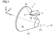
- FIG. 1 is a perspective view showing a manufacturing method according to the first embodiment of the present invention.
- the mechanical component 1 having the rotationally symmetric surface 1 ⁇ / b> A rotates around the rotation axis 10.
- the machine part 1 is a manufactured product manufactured by the manufacturing method according to an embodiment of the present invention.
- FIG. 1 shows a processing step which is one step of the manufacturing method according to one embodiment of the present invention. Therefore, in the process shown in FIG. 1, the machine part 1 can also be called a workpiece.
- the machining process includes cutting.
- the manufacturing method according to the first embodiment of the present invention may include other steps.
- the manufacturing method can include, for example, a casting process, an assembly process, an inspection process, and the like.
- the feed of the cutting edge 2A is controlled according to a three-dimensional orthogonal coordinate system.
- the Z axis corresponds to the rotation axis 10.
- the X axis and the Y axis are both perpendicular to the Z axis and perpendicular to each other.
- the X-axis can be a direction that determines a diameter dimension of the processed surface, which is also referred to as a radial direction in the cutting process.
- the Y axis is an axis orthogonal to both the X axis and the Z axis, and is called, for example, a lateral direction.
- axes defined as an X axis, a Y axis, and a Z axis in a lathe can be applied to the X axis, the Y axis, and the Z axis in the embodiment of the present invention.
- the Z-axis direction is defined as the feed (vertical feed) direction of the cutting edge 2A.
- the negative direction of the X axis is defined as the direction of cut into the machine part 1.
- the direction of the Y axis is opposite to the moving direction of the cutting edge 2A for cutting.
- the cutting edge 2A is a part of a cutting tip (not shown in FIG. 1).
- the cutting tip is detachable from the holder 2 (tool).
- FIG. 1 only the portion of the cutting edge 2A of the cutting tip is shown.
- cutting edge when it is not necessary to distinguish between the cutting edge and the cutting tip, both are collectively referred to as “cutting edge”.
- the cutting edge 2A is inclined at an angle larger than 0 ° and smaller than 90 ° with respect to the Z-axis direction. That is, the cutting edge 2A is disposed obliquely with respect to the Z-axis direction along the feeding direction of the cutting edge 2A.
- the cutting edge 2A is fed while contacting the machine component 1 along a track having an X-axis component, a Y-axis component, and a Z-axis component. Thereby, the rotationally symmetric surface 1A is processed. From the start of cutting to the end of cutting, individual regions of the cutting edge 2A from the front end 3_1 to the rear end 3_5 sequentially contact the rotationally symmetric surface 1A (ie, the processing surface).
- the rotationally symmetric surface 1A is a truncated cone surface.
- the rotationally symmetric surface 1A may be a conical surface.
- Rotationally symmetric surface 1A is defined by the ridge lines 1B inclined at a small angle theta a than 0 ° larger than 90 °. That is, the surface formed by rotating the ridge line 1B around the rotation axis 10 is the rotationally symmetric surface 1A.
- the mechanical component 1 having the rotationally symmetric surface 1A is not particularly limited.
- the mechanical component 1 is a pulley for constituting a continuously variable transmission of an automobile.
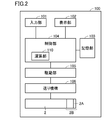
- FIG. 2 is a block diagram schematically showing the configuration of the manufacturing apparatus according to the first embodiment of the present invention.
- the manufacturing apparatus 100 according to the first embodiment of the present invention can be realized by, for example, a computerized numerical control (CNC) lathe.
- the manufacturing apparatus 100 includes an input unit 101, a display unit 102, a storage unit 103, a control unit 104, a drive unit 105, a feed mechanism 106, a holder 2, and a cutting blade 2A.
- a cutting tip 2B having the following.
- the input unit 101 is operated by the user.
- the input unit 101 receives information from the user and sends the information to the control unit 104.
- the information from the user includes information on a program selected by the user, various data necessary for manufacturing the machine part 1 (processing of the rotationally symmetric surface 1A), instructions from the user, and the like.
- the display unit 102 displays characters, symbols, figures, and the like.
- the display unit 102 can display information received by the input unit 101, a calculation result of the control unit 104, and the like.
- the storage unit 103 stores information received by the input unit 101, a program for manufacturing the machine part 1, and the like.
- This program includes a program for machining the rotationally symmetric surface 1A.
- the storage unit 103 is configured by a rewritable nonvolatile storage device. Therefore, the memory
- the program may be provided through a communication line. Also in this case, the program is stored in the storage unit 103.
- the control unit 104 is a computer configured to control the manufacturing apparatus 100 in an integrated manner.
- the control unit 104 includes a calculation unit 110.
- the calculation unit 110 performs numerical calculation based on information received by the input unit 101 and information stored in the storage unit 103.
- the calculation unit 110 may be realized by a CPU (Central Processing Unit) executing a program.
- CPU Central Processing Unit
- the drive unit 105 drives the feed mechanism 106.
- the drive unit 105 is controlled by the control unit 104.
- the feed mechanism 106 is configured to feed the holder 2 in the X-axis direction, the Y-axis direction, and the Z-axis direction.
- the holder 2 holds the cutting edge 2A by holding the cutting tip 2B.
- the holder 2 is attached to the feed mechanism 106.
- the holder 2 is fixed to the feed mechanism 106 so as not to rotate with respect to the rotation axis. Therefore, the holder 2 maintains the angle of the cutting edge 2A when processing the rotationally symmetric surface 1A.
- the holder 2 can rotate around the rotation axis when the rotational symmetry plane 1A is not processed (in the example, during maintenance of the manufacturing apparatus 100). Thereby, the advantage that the maintenance of the manufacturing apparatus 100 becomes easy, for example is acquired.
- the cutting edge 2A is formed by a ridge line between the rake face and the flank face of the cutting tip 2B.
- the ridge line is a straight line. That is, the shape of the cutting edge 2A is a linear shape.
- the term “straight” means that the shape of the cutting edge 2A is a straight line.
- the shape of the cutting tip 2B for realizing a linear cutting edge is not particularly limited. In one embodiment, the cutting tip 2B has a triangular prism shape.
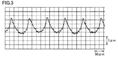
- FIG. 3 is a graph showing the surface roughness of the machined surface cut by point cutting.
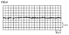
- FIG. 4 is a graph showing the surface roughness of the surface cut according to the manufacturing method according to the embodiment of the present invention. 3 and 4, the scales of the vertical axis and the horizontal axis of the graph are the same.
- the manufacturing method according to the embodiment of the present invention increases the precision (surface roughness) of the processed surface while increasing the feed rate of the cutting edge as compared with point cutting. Can do. Furthermore, in the case of point cutting, the same region in the cutting edge 2A contacts the processing surface from the start of cutting to the end of cutting. For this reason, the cutting edge wears quickly. On the other hand, according to the embodiment of the present invention, each region of the linear cutting edge 2A sequentially contacts the processing surface from the start of cutting to the end of cutting. Thereby, wear is dispersed throughout the cutting edge 2A. Therefore, the life of the cutting edge 2A can be extended.
- FIG. 5 is a schematic diagram schematically showing the cutting edge 2A projected on the XZ plane.
- FIG. 6 is a schematic view schematically showing the holder 2 and the cutting edge 2A projected onto the XY plane.
- the angle ⁇ s is a target angle that the rotationally symmetric surface 1 ⁇ / b> A (that is, the machining surface) of the mechanical component 1 forms with respect to the X axis in the XZ plane.
- the angle ⁇ s is referred to as “target angle ⁇ s ”.
- the cutting edge 2A is inclined by an angle ⁇ (first inclination angle) with respect to the X axis in the XZ plane.
- R max is the maximum radius of the rotationally symmetric surface 1A.
- R min is the minimum radius of the rotationally symmetric surface 1A.
- L XZ is the length of the cutting edge 2A on the XZ plane.
- the angle ⁇ is an inclination angle (second inclination angle) formed by the cutting edge 2A with respect to the X axis in the XY plane.
- L XY is the length of the cutting edge 2A on the XY plane.
- the angle ⁇ may be defined as an inclination angle formed by the holder with respect to the X axis in the XY plane.
- the angle ⁇ can be defined as the inclination of the holder 2 from the state in which the angle formed by the cutting edge 2A with respect to the X axis is 0 °.
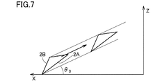
- FIG. 7 is a schematic diagram for explaining the locus of the cutting edge 2A on the XZ plane.
- FIG. 8 is a schematic diagram for explaining the locus of the cutting edge 2A on the XY plane. 7 and 8, the trajectory of cutting edge 2A forms an angle ⁇ 0 with respect to the X axis on the XZ plane. Further, the trajectory of the cutting edge 2A forms an angle ⁇ 1 with respect to the X axis on the XY plane.
- the cutting line 20 is formed on the X axis. Therefore, the cutting line 20 corresponds to the ridge line 1B of the rotationally symmetric surface 1A.
- the angle ⁇ (first inclination angle) is equal to the target angle ⁇ s in the projection image of the cutting edge 2A onto the XZ plane (see FIG. 5). I must do it.
- the holder 2 is attached to the feed mechanism 106, the inclination of the cutting edge 2A is adjusted so that the angle ⁇ matches the target angle ⁇ s .
- the inclination angle of the cutting edge 2A is measured from two or more portions of the cutting edge 2A.
- the mounting angle is corrected by inserting a shim or the like into the chip holder.
- the attachment angle of the cutting edge 2A can be corrected by the correction mechanism after measuring the inclination angle of the cutting edge 2A.
- the inclination angle of the cutting edge 2A can be measured by a measuring instrument such as the dial gauge or the presetter described above.
- FIG. 9 is a schematic diagram for explaining a machining method of the machine component 1 in the case of a track without correction.
- the tip 3_1 of the cutting edge 2A is positioned at the cutting start position.
- the “tip” refers to the end of the cutting edge 2 ⁇ / b> A that first contacts the machine part 1.
- the rotationally symmetric surface 1A is processed by sending the cutting edge 2A while making contact with the rotating machine part 1.
- t is a variable that varies from 0 to (R max ⁇ R min ).
- the rear end 3_5 of the cutting edge 2A is the end of the cutting edge 2A located on the opposite side of the front end 3_1.
- the “initial position” is a position at the start of cutting.
- the initial position of the tip 3_1 of the cutting edge 2A matches the “cutting start position”.
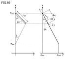
- FIG. 10 is a schematic diagram for explaining the initial positions of the front end 3_1 and the rear end 3_5 of the cutting edge 2A when the cutting edge is sent along a path without correction.
- the initial position of the tip 3_1 of the cutting edge 2A is (R max , 0, Z min ).
- the initial position of the rear end 3_5 of the cutting edge 2A is (R max + L XY ⁇ cos ⁇ , 0, Z min + L XZ ⁇ cos ⁇ ).
- the X-axis component, Y-axis component, and Z-axis component of the difference between the initial position of the leading edge of the cutting edge 2A and the initial position of the trailing edge of the cutting edge 2A are represented as (dX, dY, dZ). The following relationship is established between dX, dY, and dZ.
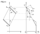
- FIG. 11 is a schematic diagram for explaining the trajectory of the rear end of the cutting edge 2A.
- the position of the rear end 3_5 of the cutting edge 2A at the end of cutting is referred to as a “final position”.
- the final position corresponds to the cutting end position.
- the final position of the rear end 3_5 of the cutting edge 2A is (R min , 0, Z max ).
- the X-axis component, Y-axis component, and Z-axis component of the difference between the final position and the initial position of the rear end 3_5 of the cutting edge 2A are represented as ( ⁇ X, ⁇ Y, ⁇ Z). The following relationship is established among ⁇ X, ⁇ Y, and ⁇ Z.
- the target angle ⁇ s formed by the rotationally symmetric surface 1A with respect to the XY plane, the maximum radius Rmax of the rotationally symmetric surface 1A, and the minimum radius Rmin of the rotationally symmetric surface 1A are design values. Angle ⁇ and angle ⁇ are measured values.
- the length L of the cutting edge 2A is a predetermined value. Therefore, these values can be acquired before starting the processing of the rotationally symmetric surface 1A.
- these values are input to the input unit 101 and stored, for example, in the storage unit 103.
- the control unit 104 can calculate tan ⁇ 0 and tan ⁇ 1 from the maximum radius R max , the minimum radius R min , the angle ⁇ , the angle ⁇ , and the length L according to the above formula. Therefore, the control unit 104 can calculate the trajectory of the tip 3_1 of the cutting edge 2A.
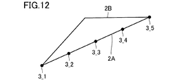
- FIG. 12 is a diagram showing five regions of the cutting edge 2A for monitoring the locus of the cutting edge 2A.
- the regions 3_2, 3_3, 3_4 of the cutting edge 2A are represented by dots. Note that the positions of the regions 3_2, 3_3, and 3_4 correspond to positions that divide the length between the front end 3_1 and the rear end 3_5 into four equal parts.
- FIG. 13 is a schematic diagram schematically showing the trajectory of the leading edge and the trailing edge of the cutting edge 2A in the RZ plane.
- the “RZ plane” is a plane determined by the radius of the rotationally symmetric surface 1A and the rotation axis (Z axis).
- FIG. 13 shows a locus 4_1 drawn by the tip 3_1 of the cutting edge 2A and a locus 4_5 drawn by the rear end 3_5 of the cutting edge 2A.
- the machining shape on the RZ plane corresponds to the envelope of the locus drawn by each region of the cutting edge 2A on the RZ plane.
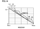
- FIG. 14 is a diagram showing a result of calculating a machining shape on the RZ plane when the angle ⁇ of the cutting edge 2A is equal to the target angle ⁇ s .
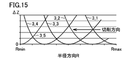
- FIG. 15 is a diagram showing the difference ⁇ Z in the Z-axis direction between the machined surface and the design surface based on the calculation result shown in FIG. Each curve in the graph is associated with the tip 3_1, the rear end 3_5, and the regions 3_2 to 3_4 of the cutting edge 2A.
- ⁇ Z 0. That is, the designed surface can be formed by cutting.
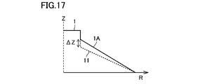
- FIG. 16 is a diagram showing a result of calculating a machining shape on the RZ plane when the angle ⁇ of the cutting edge 2A is larger than the target angle ⁇ s .
- FIG. 17 is a diagram showing the difference ⁇ Z in the Z-axis direction between the machined surface (rotationally symmetric surface 1A) and the designed surface 11 based on the calculation result shown in FIG. As shown in FIGS. 16 and 17, when ⁇ > ⁇ s , ⁇ Z increases in the positive direction as the radius R decreases. That is, in the case of ⁇ > ⁇ s , uncut portions are generated.
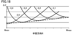
- FIG. 18 is a diagram illustrating a result of calculating a machining shape on the RZ plane when the angle ⁇ of the cutting edge 2A is smaller than the target angle ⁇ s .
- FIG. 19 is a diagram showing the difference ⁇ Z in the Z-axis direction between the machining surface (rotationally symmetric surface 1A) and the designed surface 11 based on the calculation result shown in FIG. As shown in FIGS. 18 and 19, when ⁇ ⁇ s , ⁇ Z increases in the negative direction as the radius R decreases. That is, when ⁇ ⁇ s , excessive cutting occurs.
- the angle ⁇ of the cutting edge 2A must be matched with the angle ⁇ s .
- the angle ⁇ deviates from the target angle ⁇ s , uncut or excessive cutting occurs.
- the angle ⁇ of the cutting edge 2A can be adjusted after the holder 2 is attached to the feed mechanism 106.
- a mechanism portion tends to be less rigid than the other portions of the holder 2. Therefore, when cutting a hard material (for example, hardened steel), the inclination of the cutting edge 2A may vary. When the inclination of the cutting edge 2A varies, it is more difficult to machine the machine part as designed.
- the cutting start position and the trajectory are corrected according to the angle ⁇ and the angle ⁇ of the cutting edge 2A.
- FIG. 20 is an XY plan view for schematically explaining the manufacturing method according to the first embodiment of the present invention.
- FIG. 21 is an RZ plan view for schematically explaining the manufacturing method according to the first embodiment of the present invention.
- the cutting start position is shifted from the position on the X axis by the correction amount ⁇ Y in the Y axis direction.
- the coordinates of the cutting start position that is, the initial position of the tip 3_1 of the cutting edge 2A is (R max , ⁇ Y, Z min ).
- the cutting edge 2A is inclined at an angle larger than 0 ° and smaller than 90 ° with respect to the Z-axis.
- the cutting edge 2A is sent and the rotationally symmetric surface 1A is processed.
- the coordinates (X, Y, Z) of the tip 3_1 of the cutting edge 2A change along the trajectory (R max ⁇ t, ⁇ Y ⁇ t ⁇ tan ⁇ 1 ′, Z min + t ⁇ tan ⁇ 0 ′).
- t is a variable that varies from 0 to (R max ⁇ R min ). Therefore, the trajectory has a movement amount in the directions of all the axes of the X axis, the Y axis, and the Z axis. That is, the direction of the trajectory of the cutting edge is a direction that crosses each of the X axis, the Y axis, and the Z axis.
- the cutting line 20 forms an angle ⁇ with respect to the X axis on the XY plane and passes through the origin of the XY coordinate system.
- the cutting start position moves by ⁇ Y in the Y-axis direction.
- the angles ⁇ 0 and ⁇ 1 are replaced with the angles ⁇ ′ 0 and ⁇ ′ 1 .
- the angle of the processed surface can be matched with the target angle ⁇ s . Therefore, the machine part 1 can be manufactured with high accuracy. Furthermore, the change of the program for operating the manufacturing apparatus 100 can be reduced.
- FIG. 22 is a diagram for explaining the initial positions of the front end 3_1 and the rear end 3_5 of the cutting edge 2A when the cutting edge 2A is sent along the corrected trajectory.
- tip 3_1 of cutting edge 2A is located on the circumference of radius R max in the XY plane.
- a straight line connecting the tip 3_1 and the origin forms an angle ⁇ with respect to the X axis on the XY plane.
- the position of the tip 3_1 of the cutting edge 2A is represented as (R max cos ⁇ , R max sin ⁇ , Z max ).
- the X ′ axis and the Y ′ axis are axes obtained by rotating the X axis and the Y axis by an angle ⁇ clockwise with respect to the Z axis, respectively.
- the angle ⁇ is an angle when the attachment angle of the cutting edge 2A coincides with the target angle ⁇ s in the X′Z plane.
- the X-axis component, Y-axis component, and Z-axis component of the difference between the initial position of the tip 3_1 of the cutting edge 2A and the initial position of the rear end 3_5 of the cutting edge 2A are expressed as (dX ′, dY ′, dZ).
- dX ′ dY ′
- dZ dX-axis components of the difference between the initial position of the leading edge of the cutting edge 2A and the initial position of the trailing edge of the cutting edge 2A when the cutting edge is sent along a path without correction.
- Y-axis component Y-axis component
- Z-axis component see FIG. 10
- FIG. 23 is a schematic diagram for explaining the trajectory of the rear end 3_5 of the cutting edge 2A.
- the projected image of the cutting edge 2A on the X′Z plane is tilted with respect to the X ′ axis.
- the inclination angle of the cutting edge 2A coincides with the target angle ⁇ s .
- the X-axis component, Y-axis component, and Z-axis component of the difference between the final position and the initial position of the rear end 3_5 of the cutting edge 2A are represented as ( ⁇ X ′, ⁇ Y ′, ⁇ Z).
- ⁇ X ′, ⁇ Y ′, and ⁇ Z The following relationship holds between ⁇ X ′, ⁇ Y ′, and ⁇ Z.
- ⁇ X ′, ⁇ Y ′, and ⁇ Z are derived by replacing the angle ⁇ in ⁇ X, ⁇ Y, and ⁇ Z with ( ⁇ + ⁇ ).
- an angle formed by the trajectory of the rear end 3_5 of the cutting edge 2A with respect to the X ′ axis is denoted by ⁇ . From the above formula, the angle ⁇ ′ 1 is expressed as follows.
- ⁇ X ′ is expressed as follows in the original XY coordinate system.
- FIG. 24 is a diagram illustrating the corrected trajectory of the cutting edge 2A on the XZ plane.
- FIG. 25 is a diagram illustrating the corrected trajectory of the cutting edge 2A on the XY plane.
- angle ⁇ ′ 0 and angle ⁇ ′ 1 are angles (program angles) used in a program for processing rotationally symmetric surface 1A in manufacturing apparatus 100 (see FIG. 2). is there.
- the angle ⁇ is an angle formed by the locus of the cutting edge 2A and the cutting line 20 on the XY plane.
- the angle ⁇ is an angle formed by the cutting line 20 and the X axis on the XY plane.
- the length L XY is the length of the projected image on the XY plane of the cutting edge 2A.
- the angle ⁇ , the angle ⁇ , and the length L XY are expressed as follows.
- FIG. 26 is a diagram showing a result of calculating a processing shape on the RZ plane when the angle ⁇ of the cutting edge 2A is larger than the target angle ⁇ s .
- FIG. 27 is a diagram showing the result of calculating the machining shape on the RZ plane when the angle ⁇ of the cutting edge 2A is smaller than the target angle ⁇ s .
- 26 and 27 show the trajectories of the tip 3_1, the rear end 3_5, and the regions 3_2, 3_3, and 3_4 of the cutting edge 2A.
- ⁇ Z can be maintained at 0 from the start of cutting to the end of cutting. That is, according to the first embodiment of the present invention, the rotationally symmetric surface 1A can be processed so that the ridge line 1B forms the target angle ⁇ s with respect to the XY plane.
- the angle ⁇ and the angle ⁇ of the cutting edge 2A maintain the same value, further correction of the cutting start position and the trajectory is unnecessary. Since the holder 2 is configured to prevent the cutting edge 2 from rotating, the angle ⁇ and the angle ⁇ of the cutting edge 2A can be maintained. By sending the cutting edge 2A along the trajectory from the set cutting start position, it is possible to repeatedly manufacture a machine part having high accuracy. Further, as described above, in the embodiment of the present invention, each region of the linear cutting edge 2A sequentially contacts the rotationally symmetric surface 1A from the start of cutting to the end of cutting. Therefore, it is excellent also in terms of the surface roughness of the rotationally symmetric surface 1A and the life of the cutting edge.
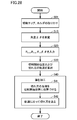
- FIG. 28 is a flowchart showing the manufacturing method according to the first embodiment of the present invention. As shown in FIG. 28, the cutting tip 2B is attached to the holder 2 in step S01. Furthermore, the holder 2 is attached to the manufacturing apparatus 100 (feed mechanism 106).
- step S10 the angle ⁇ and the angle ⁇ are measured. Since various known methods can be used to measure the angle ⁇ and the angle ⁇ , detailed description will not be repeated here. For example, the angle ⁇ and the angle ⁇ are measured using a measuring instrument such as a dial gauge or a presetter.
- steps S20 to S40 are executed when the control unit 104 reads out the program stored in the storage unit 103.
- the control unit 104 controls the display unit 102 to display a screen that prompts the user to input values necessary for processing the rotationally symmetric surface 1A.
- the user operates the input unit 101 to input values of the maximum radius R max , the minimum radius R min , the angle ⁇ s , the angle ⁇ , the angle ⁇ , and the length L to the input unit 101. That is, the input unit 101 receives the above value.
- the value received by the input unit 101 is stored in the storage unit 103, for example.
- the value received by the input unit 101 may be stored in the control unit 104, or may be stored in both the storage unit 103 and the control unit 104.
- step S30 the control unit 104 calculates the cutting start position and the trajectory of the cutting edge 2A.
- the calculation unit 110 calculates ⁇ Y, tan ⁇ ′ 0 and tan ⁇ ′ 1 .
- the calculation unit 110 calculates the length L XY , the angle ⁇ , and the angle ⁇ according to the above formulas (1) to (3).
- the calculation unit 110 calculates ⁇ Y, tan ⁇ ′ 0 and tan ⁇ ′ 1 in accordance with the above formulas (4) to (6).
- ⁇ Y, tan ⁇ ′ 0 and tan ⁇ ′ 1 are stored in the storage unit 103.
- the angle ⁇ ′ 0 and / or the angle ⁇ ′ 1 may be stored in the storage unit 103 in accordance with the contents of the program.
- step S40 the rotationally symmetric surface 1A is processed.
- the control unit 104 controls the feeding mechanism 106 by controlling the driving unit 105. Thereby, the feed of the holder 2 is controlled. That is, the control unit 104 controls the feeding of the cutting edge 2A.
- the control unit 104 positions the tip 3_1 of the cutting edge 2A at the cutting start position (R max , ⁇ Y, Z min ) (step S41).
- the control unit 104 controls the cutting edge so that the position of the tip 3_1 of the cutting edge 2A changes along the trajectory (R max ⁇ t, ⁇ Y ⁇ t ⁇ tan ⁇ ′ 1 , Z min + t ⁇ tan ⁇ ′ 0 ).
- 2A is sent (step S42).
- the control unit 104 moves the cutting edge 2A while changing the variable t from 0 to (R max ⁇ R min ) so that the tip 3_1 of the cutting edge 2A is positioned at the coordinates determined by the variable t.
- step S40 the process of step S40 is repeated.
- the control unit 104 reads ⁇ Y, tan ⁇ ′ 0 , tan ⁇ ′ 1 from the storage unit 103, and executes the processes of steps S41 and S42. Note that while the same process is repeated, the control unit 104 may store ⁇ Y, tan ⁇ ′ 0 , tan ⁇ ′ 1 .
- the control unit 104 calculates ⁇ Y, tan ⁇ ′ 0 , tan ⁇ ′ 1 before the process of step S40, and then calculates a cutting start position and a trajectory.
- the control unit 104 may calculate the correction amount ⁇ Y in step S41, and may calculate tan ⁇ ′ 0 and tan ⁇ ′ 1 in step S42. That is, the cutting start position and the trajectory may be calculated in a process that requires them.
- step S40 or before step S01 further steps necessary for manufacturing the machine part 1 may be performed.
- step S40 an inspection process for inspecting the machine part 1 may be performed.
- the computer that executes the processes of step S20 and step S30 is not limited to being the control unit 104 of the manufacturing apparatus 100.
- a computer provided outside the manufacturing apparatus 100 may execute the processes of step S20 and step S30.
- a step of receiving ⁇ Y, tan ⁇ ′ 0 , tan ⁇ ′ 1 can be added before step S40.
- various known means such as operation of the input unit 101 by the user and data transfer through a communication line can be applied.
- the measured values of the angles ⁇ and ⁇ and the predetermined values (the length L of the cutting edge 2A, the maximum radius R max of the rotationally symmetric surface 1A, the rotationally symmetric surface 1A
- the cutting start position and the trajectory can be calculated based on the minimum radius R min and the target angle ⁇ s ).
- the angle theta s can be replaced with (90 ⁇ a ). That is, in a plane determined by two of the X, Y, and Z axes, the tilt angle with respect to one axis can be replaced with the tilt angle with respect to the other axis. Also in that case, the equations (1) to (6) can be derived.
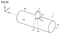
- FIG. 29 is a perspective view showing a manufacturing method according to the second embodiment of the present invention.
- the machine part 1 has a cylindrical shape.
- the rotationally symmetric surface 1A is a side surface of a cylinder.
- the rotationally symmetric surface 1 ⁇ / b> A is defined by a generatrix parallel to the rotation axis 10.
- the bus line corresponds to the ridge line 1B.
- a surface formed by rotating the bus bar around the rotation axis 10 is a rotationally symmetric surface 1A.
- the machine part 1 is a shaft.
- the type of the machine part 1 is not particularly limited.
- the cylinder shown in FIG. 29 may be a part of the machine part 1.
- the mechanical component 1 may be hollow. That is, the machine part 1 may have a cylindrical shape.
- FIG. 30 is a schematic diagram schematically showing the cutting edge 2A projected on the YZ plane.
- L YZ is the projection length of the cutting edge 2A onto the YZ plane.
- R is the radius of the rotationally symmetric surface 1A.
- Z max is the maximum value of the Z coordinate of the rotationally symmetric surface 1A.
- Z min is the minimum value of the Z coordinate of the rotationally symmetric surface 1A.
- Z max is also referred to as the height of the machine part 1.
- the angle ⁇ may be defined as an inclination angle formed by the holder 2 with respect to the Z axis in the YZ plane.
- the angle ⁇ can be defined as the inclination of the holder 2 from the state in which the angle formed by the cutting edge 2A with respect to the Z axis is 90 °.
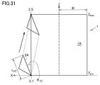
- FIG. 31 is a schematic diagram schematically showing the cutting edge 2A projected onto the XZ plane.
- the angle ⁇ XZ is an inclination angle (second inclination angle) formed by the cutting edge 2A with respect to the Z axis in the XZ plane.
- the cutting tip 2B is attached to the holder 2 so that the angle ⁇ XZ is as close to 0 ° as possible.
- L XZ is the projection length of the cutting edge 2A onto the XZ plane.
- FIG. 32 is a schematic diagram schematically showing the cutting edge 2A projected onto the XY plane.
- the angle ⁇ XY is an inclination angle formed by the cutting edge 2A with respect to the Y axis in the XY plane.
- L XY is the projection length of the cutting edge 2A onto the XY plane.
- the 32 represents the rotationally symmetric surface 1A projected on the XY plane.
- the cutting edge 2A moves on the XY plane along the tangent line of this circle.
- the position of the tip 3_1 of the cutting edge 2A at the start of cutting corresponds to a contact point of a circle.
- the angle ⁇ XZ can be a negative value ( ⁇ XZ ⁇ 0).
- the X-axis component, Y-axis component, and Z-axis component of the difference between the initial position of the tip 3_1 of the cutting edge 2A and the initial position of the rear end 3_5 of the cutting edge 2A are represented as (dX, dY, dZ).
- the signs of the angles ⁇ XY , ⁇ XZ , and ⁇ YZ are defined so that the following relational expression is satisfied.
- L YZ , L XZ and L XY are expressed according to the following equations.
- L represents the length of the cutting edge 2A.
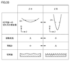
- FIG. 33 is a diagram for explaining the angle ⁇ of the cutting edge on the YZ plane. Referring to FIG. 33, when the cutting edge 2A is projected onto the RZ plane, the projected image is a curve.
- the “RZ plane” is a plane determined by the radius (R) and the rotation axis (Z) of the rotationally symmetric surface 1A.
- the contact resistance of the cutting edge 2A is large because the cutting width is large.
- the surface roughness of the processed surface is small.
- the contact resistance of the cutting edge 2A is small because the cutting width is small.
- the surface roughness of the processed surface is large.
- the contact resistance and the surface roughness change by changing the angle ⁇ .
- Contact resistance and surface roughness are in a trade-off relationship with each other. Therefore, the angle ⁇ can be determined so that both the contact resistance and the surface roughness are required levels.
- the angle ⁇ is determined so that 0 ° ⁇ ⁇ 90 °.
- the angle ⁇ is 20 ° ⁇ ⁇ ⁇ 70 °. More preferably, the angle ⁇ is 30 ° ⁇ ⁇ ⁇ 60 °, and still more preferably, the angle ⁇ is 45 °.
- the angle ⁇ XZ must match 0 ° in the projected image of the cutting edge 2A on the XZ plane.
- the holder 2 is attached to the feed mechanism 106, it is necessary to adjust the angle of the cutting edge 2A so that the angle ⁇ XZ becomes equal to 0 °.
- the method exemplified in the first embodiment is applied.
- Track FIG. 34 is a YZ plan view for explaining a machining method of the machine component 1 in the case of a track without correction.
- FIG. 35 is an XZ plan view for explaining a machining method of the machine part 1 in the case of a track without correction.
- the tip 3_1 of the cutting edge 2A is positioned at the cutting start position.
- the cutting start position in the case of a trajectory without correction is set to the origin of the three-dimensional orthogonal coordinate system.
- the rotationally symmetric surface 1A is processed by sending the cutting edge 2A while making contact with the rotating machine part 1.
- the cutting edge 2A moves linearly in the XZ plane and moves linearly in the YZ plane.
- XZ program angle means an angle formed by the moving direction of the cutting edge 2A in the XZ plane and the Z axis.
- YZ program angle means an angle formed by the moving direction of the cutting edge 2A in the YZ plane and the Z axis.
- the XZ program angle and the YZ program angle are represented as ⁇ 1 and ⁇ 2 , respectively.
- the angles ⁇ 1 and ⁇ 2 can be expressed according to the following equations.
- FIG. 36 is a diagram for explaining the relationship between the program angle ⁇ 2 on the YZ plane and the first tilt angle ⁇ .
- a triangle is shown.
- the length of one side of the triangle is Z max .
- the other side of the triangle corresponds to the cutting edge 2A. Therefore, the length of the side is L YZ .
- the angle formed by these two sides is ⁇ .
- a perpendicular line is drawn from the rear end 3_5 of the cutting edge 2A to the side of the length Z max ⁇ Z min .
- the machine part 1 is processed according to the following procedure.
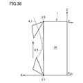
- FIG. 38 is a schematic diagram schematically showing the trajectory of the tip and rear ends of the cutting edge 2A in the RZ plane.
- FIG. 38 shows a locus 4_1 drawn by the tip 3_1 of the cutting edge 2A and a locus 4_5 drawn by the rear end 3_5 of the cutting edge 2A.
- the machining shape on the RZ plane corresponds to the envelope of the locus drawn by each region of the cutting edge 2A on the RZ plane.
- FIG. 39 is a diagram illustrating a result of calculating a machining shape on the RZ plane in the case where the second inclination angle ⁇ XZ of the cutting edge 2A is equal to 0 °.
- FIG. 41 is a diagram illustrating a result of calculating a machining shape on the RZ plane when the second inclination angle ⁇ XZ of the cutting edge 2A is smaller than 0 °.
- FIG. 42 is a diagram showing a difference ⁇ R in the R-axis direction between the machining surface (rotationally symmetric surface 1A) and the designed surface 11 based on the calculation result shown in FIG. As shown in FIGS. 41 and 42, when ⁇ XZ ⁇ 0, ⁇ R increases in the negative direction as Z increases. That is, excessive cutting occurs when ⁇ XZ ⁇ 0.
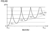
- FIG. 43 is a diagram illustrating a result of calculating a machining shape on the RZ plane in the case where the second inclination angle ⁇ XZ of the cutting edge 2A is larger than 0 °.
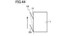
- FIG. 44 is a diagram showing the difference ⁇ R in the R-axis direction between the machining surface (rotationally symmetric surface 1A) and the designed surface 11 based on the calculation result shown in FIG. As shown in FIGS. 43 and 44, when ⁇ XZ > 0, ⁇ R increases in the positive direction as Z increases. That is, when ⁇ XZ > 0, uncut material is left.
- the horizontal axis represents the position in the Z-axis direction with Z min as a reference.
- the angle ⁇ XZ of the cutting edge 2A in order to form a designed surface by cutting, the angle ⁇ XZ of the cutting edge 2A must be made equal to 0 °. However, in reality, it is often difficult to make the angle ⁇ XZ of the cutting edge 2A coincide with 0 °. When the angle ⁇ XZ of the cutting edge 2A deviates from 0 °, the workpiece remains uncut or excessively cut.
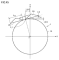
- FIG. 45 is an XY plan view for schematically explaining the manufacturing method according to the second embodiment of the present invention.
- FIG. 46 is a YZ plan view for schematically illustrating the manufacturing method according to the second embodiment of the present invention.
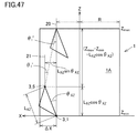
- FIG. 47 is an XZ plan view for schematically explaining the manufacturing method according to the second embodiment of the present invention.
- the cutting start position is shifted by the correction amount
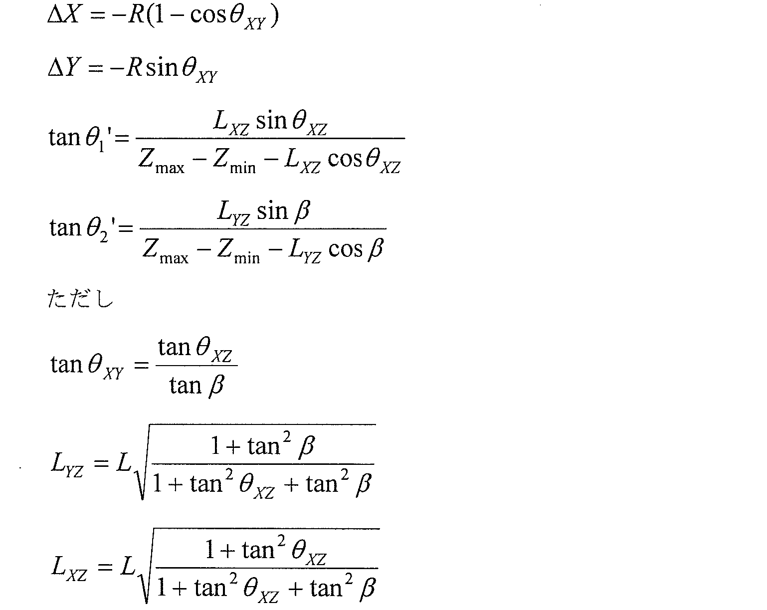
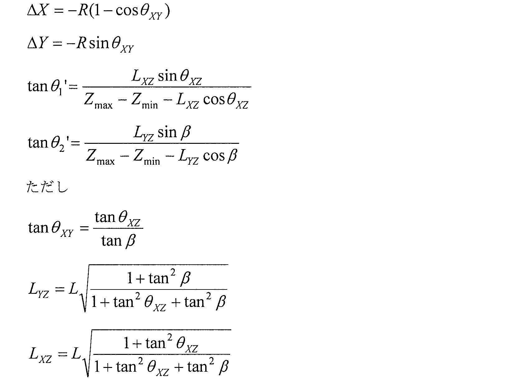
- the correction amounts ⁇ X and ⁇ Y of the cutting start position can be expressed by the following equations.
- the cutting edge 2A is sent and the rotationally symmetric surface 1A is processed.
- the coordinates (X, Y, Z) of the tip 3_1 of the cutting edge 2A change according to the program angles ⁇ 1 ′ and ⁇ 2 ′.
- the trajectory has a movement amount in the directions of all axes of the X axis, the Y axis, and the Z axis. That is, the direction of the trajectory of the cutting edge is a direction that crosses each of the X axis, the Y axis, and the Z axis.
- the cutting line 20 corresponds to the locus of the portion of the cutting edge 2A that is in contact with the rotationally symmetric surface 1A.
- the cutting line 20 corresponds to a straight line connecting the tip 3_1 of the cutting edge 2A at the cutting start position and the rear end 3_5 of the cutting edge 2A at the cutting end position.
- the cutting line 20 is parallel to the Z axis.
- the cutting line 20 is shifted in the positive direction of the Y axis by ⁇ Y from the Z axis on the YZ plane.
- the cutting line 20 is shifted in the positive direction of the X axis by ⁇ X from the Z axis on the XZ plane.
- the cutting start position moves by ⁇ Y in the Y-axis direction and shifts by ⁇ X in the X-axis direction.
- the program angles ⁇ 1 and ⁇ 2 are replaced with the program angles ⁇ 1 ′ and ⁇ 2 ′.
- Expressions (7) and (8) indicate that ⁇ X and ⁇ Y change based on tan ⁇ and tan ⁇ XZ .
- the X-axis coordinate and the Y-axis coordinate of the cutting start position include ⁇ X and ⁇ Y, respectively. Therefore, the X-axis coordinate and the Y-axis coordinate of the cutting start position depend on the angle ⁇ and the angle ⁇ XZ , respectively. Thereby, a machine part having a rotationally symmetric surface defined by a generatrix parallel to the rotation axis can be machined with high accuracy.
- the program angles ⁇ 1 ′ and ⁇ 2 ′ can be expressed as follows.
- ⁇ 2 ′ ⁇ 2 .
- the program angle ⁇ 1 ′ is obtained as follows.
- the height (position in the Z-axis direction) of the rear end 3_5 of the cutting edge 2A is expressed as L XZ cos ⁇ XZ .
- the distance from the cutting line 20 to the rear end 3_5 of the cutting edge 2A is represented as L XZ sin ⁇ XZ .
- the imaginary line 21 is a straight line that passes through the rear end 3_5 of the cutting edge 2A and is parallel to the cutting line 20 and the Z axis. Therefore, the distance between the virtual line 21 and the cutting line 20 is equal to L XZ sin ⁇ XZ .
- the program angle ⁇ 1 ′ is equal to the angle formed by the trajectory on the XZ plane of the rear end 3_5 of the cutting edge 2A with the virtual line 21.
- the virtual line 21 and the cutting line 20 are parallel. Therefore, the program angle ⁇ 1 ′ is equal to the angle formed by the trajectory on the XZ plane of the rear end 3_5 of the cutting edge 2A with the virtual line 21.
- a triangle is formed by the trajectory of the rear end 3_5 of the cutting edge 2A on the XZ plane, the cutting line 20, and the perpendicular line dropped from the position of the rear end 3_5 of the cutting edge 2A at the start of cutting to the cutting line 20. .
- the relationship tan ⁇ 1 ′ L XZ sin ⁇ XZ / (Z max ⁇ Z min ⁇ L XZ cos ⁇ XZ ) is established.
- FIG. 48 is a diagram illustrating a result of calculating a processing shape on the RZ plane when the second inclination angle ⁇ XZ of the cutting edge 2A is smaller than 0 °.
- FIG. 49 is a diagram showing a result of calculating a machining shape on the RZ plane in the case where the second inclination angle ⁇ XZ of the cutting edge 2A is larger than 0 °.
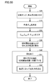
- FIG. 50 is a flowchart showing a manufacturing method according to the second embodiment of the present invention.
- the processing of each step shown in FIG. 50 is basically the same as the processing of the corresponding step shown in FIG.
- the cutting tip 2B is attached to the holder 2.
- the holder 2 is attached to the manufacturing apparatus 100 (feed mechanism 106).
- step S10 the angle ⁇ XZ is measured. Since various known methods can be used to measure the angle ⁇ XZ , detailed description will not be repeated here.
- the angle ⁇ XZ is measured using a measuring instrument such as a dial gauge or a presetter .
- the angle ⁇ is a predetermined angle. However, the angle ⁇ may be measured together with the angle ⁇ XZ .
- steps S20 to S40 are executed when the control unit 104 reads out the program stored in the storage unit 103.
- the control unit 104 controls the display unit 102 to display a screen that prompts the user to input values necessary for processing the rotationally symmetric surface 1A.
- the user operates the input unit 101, an input unit 101, the maximum value Z max of Z-axis coordinate of the rotationally symmetric surface 1A, a minimum value Z min of the Z-axis coordinate of the rotationally symmetric surface 1A, the angle beta, the angle theta XZ And enter a value for length L. That is, the input unit 101 receives the above value.
- the value received by the input unit 101 is stored in the storage unit 103, for example.
- the value received by the input unit 101 may be stored in the control unit 104, or may be stored in both the storage unit 103 and the control unit 104.
- step S30 the control unit 104 calculates the cutting start position and the trajectory of the cutting edge 2A.
- the calculation unit 110 calculates ⁇ X, ⁇ Y, tan ⁇ 1 ′ and tan ⁇ 2 ′ according to the equations (7) to (10).
- ⁇ X, ⁇ Y, tan ⁇ 1 ′ and tan ⁇ 2 ′ are stored in the storage unit 103.
- the angle ⁇ 1 ′ and / or the angle ⁇ 2 ′ may be stored in the storage unit 103 according to the contents of the program.
- the coordinates of the start point (cutting start position) of the track and the coordinates of the end point (cutting end position) of the track may be stored in the storage unit 103.
- step S40 the rotationally symmetric surface 1A is processed.
- the control unit 104 controls the feeding mechanism 106 by controlling the driving unit 105. Thereby, the feed of the holder 2 is controlled. That is, the control unit 104 controls the feeding of the cutting edge 2A.
- the control unit 104 positions the tip 3_1 of the cutting edge 2A at the cutting start position (R + ⁇ X, ⁇ Y, Z min ) (step S41).
- the X-axis coordinate and the Y-axis coordinate of the cutting start position depend on the first inclination angle ⁇ and the second inclination angle ⁇ XZ .
- the tip 3_1 of the cutting edge 2A is set such that the X-axis coordinate and the Y-axis coordinate of the tip 3_1 of the cutting edge 2A are coordinates based on the first inclination angle ⁇ and the second inclination angle ⁇ XZ. Can be included.
- the control unit 104 controls the cutting edge 2A so that the position of the tip 3_1 of the cutting edge 2A changes along the trajectory (R + ⁇ X ⁇ t ⁇ tan ⁇ 1 ′, ⁇ Y ⁇ t ⁇ tan ⁇ 2 ′, Z min + t).
- Step S42 the control unit 104 moves the cutting edge 2A while changing the variable t from 0 to (Z max ⁇ Z min ) so that the tip 3_1 of the cutting edge 2A is positioned at the coordinates determined by the variable t.
- step S40 the process of step S40 is repeated.
- the control unit 104 reads ⁇ X, ⁇ Y, tan ⁇ 1 ′ and tan ⁇ 2 ′ from the storage unit 103, and executes the processes of steps S41 and S42. Note that while the same processing is repeated, the control unit 104 may store ⁇ X, ⁇ Y, tan ⁇ 1 ′, and tan ⁇ 2 ′.
- the control unit 104 calculates ⁇ X, ⁇ Y, tan ⁇ 1 ′, and tan ⁇ 2 ′ before the process of step S40, and then calculates the cutting start position and the trajectory. .
- the control unit 104 may calculate the correction amounts ⁇ X and ⁇ Y in step S41, and may calculate tan ⁇ 1 ′ and tan ⁇ 2 ′ in step S42. That is, the cutting start position and the trajectory may be calculated in a process that requires them.
- step S40 or before step S01 further steps necessary for manufacturing the machine part 1 may be performed.
- step S40 an inspection process for inspecting the machine part 1 may be performed.
- the computer that executes the processes of step S20 and step S30 is not limited to being the control unit 104 of the manufacturing apparatus 100.
- a computer provided outside the manufacturing apparatus 100 may execute the processes of step S20 and step S30.
- a step of receiving ⁇ X, ⁇ Y, tan ⁇ 1 ′ and tan ⁇ 2 ′ can be added before step S40.
- various known means such as operation of the input unit 101 by the user and data transfer through a communication line can be applied.
- the axes serving as references for the angles ⁇ , ⁇ YZ , and ⁇ XZ may be set to the Y axis, the X axis, and the Z axis, respectively.
- the tilt angle with respect to one axis can be replaced with the tilt angle with respect to the other axis. Also in that case, the equations (7) to (10) can be derived.
- the directions of the X axis, the Y axis, and the Z axis are not limited as shown in each drawing.
- the positive direction of each of the X axis, Y axis, and Z axis may be opposite to the direction shown in the drawing. It is also possible to exchange the X axis, the Y axis, and the Z axis with each other.
- each embodiment of the present invention can also be applied to machining a workpiece that is not limited to machine parts.
Landscapes
- Engineering & Computer Science (AREA)
- Physics & Mathematics (AREA)
- Mechanical Engineering (AREA)
- Automation & Control Theory (AREA)
- Manufacturing & Machinery (AREA)
- General Physics & Mathematics (AREA)
- Human Computer Interaction (AREA)
- Geometry (AREA)
- Numerical Control (AREA)
- Turning (AREA)
- Milling Processes (AREA)
- Other Investigation Or Analysis Of Materials By Electrical Means (AREA)
- Automatic Control Of Machine Tools (AREA)
Abstract
Description
最初に本発明の実施態様を列記して説明する。
(2)好ましくは、切削開始位置において切れ刃(2A)の第1の端部(3_1)が機械部品(1)に接触する。切削開始位置から切削終了位置まで軌道に沿って切れ刃(2A)を送る間に、切れ刃(2A)の第1の端部(3_1)から、第1の端部(3_1)と反対側に位置する切れ刃(2A)の第2の端部(3_5)まで、切れ刃(2A)の異なる部分が順次接触する。

(10)好ましくは、機械部品の製造装置は、上記(1)~(9)のいずれかに記載の方法を実行する装置である。
(11)本発明の一態様に係る回転対称面の加工方法は、回転軸線(10)に対して0°より大きく90°より小さい角度で傾斜した稜線によって規定された回転対称面の加工方法であって、回転対称面(1A)の回転軸線(10)をZ軸とし、回転対称面(1A)の径方向の軸をX軸とし、Z軸およびX軸の両方に直交する軸をY軸と規定した三次元直交座標系において、Z軸に対して0°より大きく90°より小さい角度で傾斜した直線状の切れ刃(2A)を、X軸上の位置からY軸方向に沿ってずらした切削開始位置に位置決めするステップ(S41)と、切れ刃(2A)を、切削開始位置から、X軸成分、Y軸成分およびZ軸成分を有する軌道に沿って、回転している工作物(1)に接触させながら送ることによって回転対称面(1A)を加工するステップとを備える。

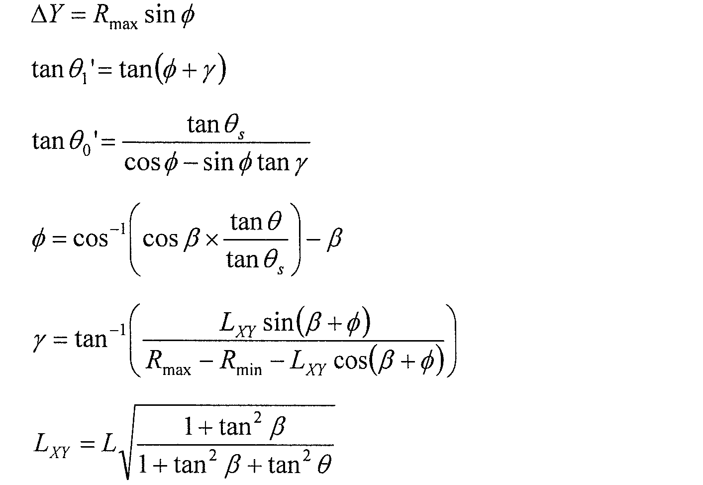
(13)本発明の一態様に係るプログラムは、回転軸線(10)に対して0°より大きく90°より小さい角度で傾斜した稜線(1B)によって規定された回転対称面(1A)を有する機械部品(1)を製造するためのプログラムである。プログラムは、回転対称面(1A)の回転軸線(10)をZ軸とし、回転対称面(1A)の径方向の軸をX軸とし、Z軸およびX軸の両方に直交する軸をY軸と規定した三次元直交座標系において、直線状の切れ刃(2A)の長さ(L)、XZ平面において、X軸に対して切れ刃(2A)がなす第1の傾斜角度(θ)、XY平面において、X軸に対して切れ刃(2)がなす第2の傾斜角度(β)、回転対称面(1A)の最大半径(Rmax)、回転対称面(1A)の最小半径(Rmin)、および稜線(1B)がXZ平面において、X軸に対してなす目標角度(θs)を受け付けるステップと、Z軸に対して0°より大きく90°より小さい角度で傾斜した切れ刃(2A)を、切削開始位置に位置決めするステップと、切れ刃(2A)を、切削開始位置から軌道に沿って、回転している機械部品(1)に接触させながら送ることによって回転対称面(1A)を加工するステップをコンピュータに実行させる。切削開始位置の座標は、(X,Y,Z)=(Rmax,ΔY,Zmin)と表現され、軌道は、(X,Y,Z)=(Rmax-t,ΔY-t×tanθ1’,Zmin+t×tanθ0’)と表現され、Rmaxは、回転対称面(1A)の最大半径であり、Rminは、回転対称面(1A)の最小半径であり、tは、0からRmax-Rminまで変化する変数であり、θsは、目標角度であり、ΔY,tanθ1’,tanθ0’が以下の式に従い、
(14)本発明の一態様に係る回転対称面の加工方法は、回転軸線(10)に対して平行な母線(1B)によって規定された回転対称面(1A)の加工方法である。加工方法は、回転軸線(10)をZ軸とし、回転対称面(1A)の径方向の軸をX軸とし、Z軸およびX軸の両方に直交する軸をY軸とする三次元直交座標系において、直線状の切れ刃(2A)を、YZ平面上において0°より大きく90°よりも小さい第1の傾斜角度(β)でZ軸に対して傾けられた状態で、切削開始位置に位置付けるステップと、切れ刃(2A)の異なる部分が順次接触するように、切れ刃(2A)を、切削開始位置から、回転している機械部品(1)に接触させながら送ることによって回転対称面(1A)を加工するステップとを備える。切削開始位置は、X軸座標およびY軸座標を含む。X軸座標およびY軸座標の各々は、第1の傾斜角度(β)、および、切れ刃がXZ平面上においてZ軸となす第2の傾斜角度(θXZ)に基づいて定められる。

以下、図面に基づいて本発明の実施の形態を説明する。なお、以下の図面において同一または相当する部分には同一の参照番号を付し、その説明は繰返さない。また、説明を分かりやすくするために、図面において、発明の構成要素の一部のみが示される場合がある。
図1は、本発明の第1の実施形態に係る製造方法を示した斜視図である。図1に示されるように、回転対称面1Aを有する機械部品1が、回転軸線10を中心として回転する。機械部品1は、本発明の一実施形態に係る製造方法によって製造される製造品である。
図5は、XZ平面上に射影された切れ刃2Aを模式的に示した模式図である。図6は、XY平面上に射影されたホルダ2および切れ刃2Aを模式的に示した模式図である。
切れ刃を補正なし軌道に沿って送る場合、切れ刃2AのXZ面への射影像(図5参照)において、角度θ(第1の傾斜角度)が目標角度θsに一致しなければならない。ホルダ2が送り機構106に取り付けられたときに、角度θが目標角度θsに一致するように、切れ刃2Aの傾きが調整される。
図9は、補正なし軌道の場合の機械部品1の加工方法を説明するための模式図である。図9に示されるように、まず、切れ刃2Aの先端3_1が切削開始位置に位置付けられる。「先端」は、機械部品1に最初に接触する切れ刃2Aの端部を指す。切削開始位置における先端3_1の座標は、(X,Y,Z)=(Rmax,0,Zmin)である。
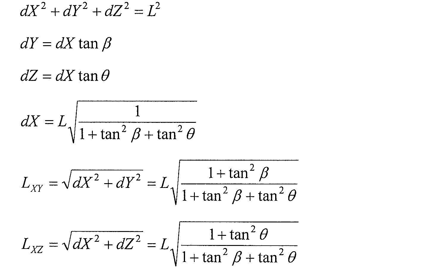

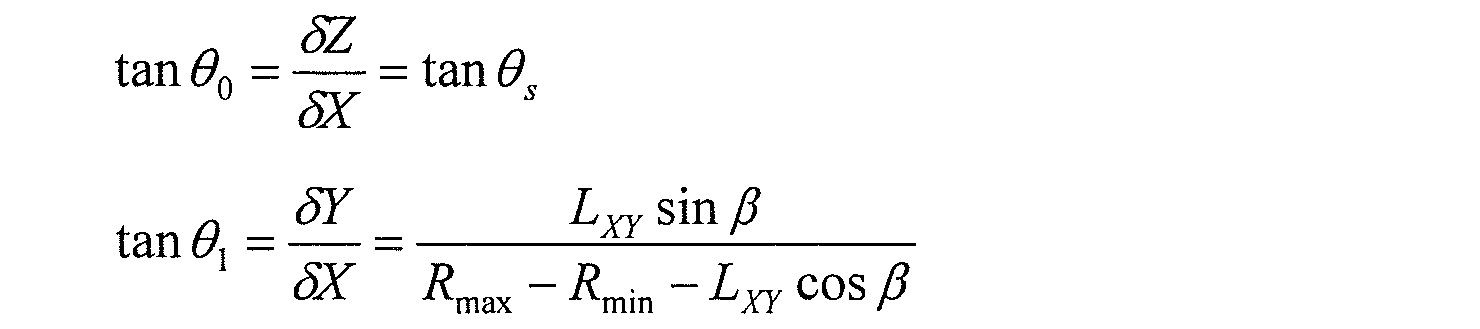
図12は、切れ刃2Aの軌跡をモニタするための切れ刃2Aの5つの領域を示した図である。先端3_1および後端3_5に加えて、切れ刃2Aの領域3_2,3_3,3_4が、点によって表される。なお、領域3_2,3_3,3_4の位置は、先端3_1と後端3_5との間の長さを4等分する位置に対応する。
本発明の第1の実施の形態では、切れ刃2Aの角度θおよび角度βに応じて切削開始位置および軌道が補正される。
図20は、本発明の第1の実施の形態に係る製造方法を模式的に説明するためのXY平面図である。図21は、本発明の第1の実施の形態に係る製造方法を模式的に説明するためのRZ平面図である。図20において示されるように、本発明の第1の実施の形態では、切削開始位置を、X軸上の位置からY軸方向に補正量ΔYだけずらす。切削開始位置の座標、すなわち切れ刃2Aの先端3_1の初期位置は、(Rmax,ΔY,Zmin)である。なお、図21に示されるとおり、切れ刃2AはZ軸に対して0°より大きく90°より小さい角度で傾けられている。
図22は、補正された軌道に沿って切れ刃2Aを送る場合における、切れ刃2Aの先端3_1および後端3_5の初期位置を説明するための図である。図22を参照して、切れ刃2Aの先端3_1は、XY平面において半径Rmaxの円周上に位置する。先端3_1と原点とを結ぶ直線は、XY平面において、X軸に対して角度φをなす。切れ刃2Aの先端3_1の位置は、(Rmaxcosφ,Rmaxsinφ,Zmax)と表される。

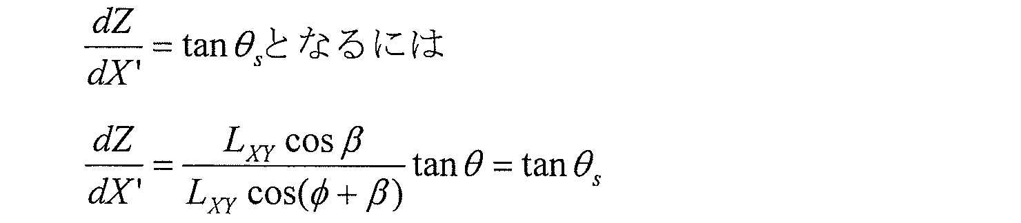







図26は、切れ刃2Aの角度θが目標角度θsよりも大きい場合における、RZ平面上の加工形状を計算した結果を示した図である。図27は、切れ刃2Aの角度θが目標角度θsよりも小さい場合における、RZ平面上の加工形状を計算した結果を示した図である。図26および図27には、切れ刃2Aの先端3_1、後端3_5および領域3_2,3_3,3_4の軌跡が示される。角度θが目標角度θsよりも大きい場合、角度θが目標角度θsよりも小さい場合のいずれにおいても、切削開始から切削終了までの間、ΔZを0に維持できる。すなわち、本発明の第1の実施の形態によれば、稜線1BがXY平面に対して目標角度θsをなすように、回転対称面1Aを加工することができる。
図29は、本発明の第2の実施形態に係る製造方法を示した斜視図である。この実施の形態では、機械部品1は円柱形を有する。回転対称面1Aは、円柱の側面である。回転対称面1Aは、回転軸線10に平行な母線によって規定される。母線は、稜線1Bに相当する。母線を回転軸線10の周囲に回転させることによって形成される面が回転対称面1Aである。
図30は、YZ平面上に射影された切れ刃2Aを模式的に示した模式図である。図30に示されるように、角度β(=θYZ)は、YZ平面において、切れ刃2AがZ軸に対してなす傾斜角度(第1の傾斜角度)である。LYZは、切れ刃2AのYZ平面への射影長さである。Rは、回転対称面1Aの半径である。Zmaxは、回転対称面1AのZ座標の最大値である。Zminは、回転対称面1AのZ座標の最小値である。Z=ZminをZ軸の原点の位置とする。すなわちZmin=0である。以下では、Zmaxを機械部品1の高さとも呼ぶ。



切れ刃2Aを補正なし軌道に沿って送る場合、切れ刃2AのXZ面への射影像において、角度θXZが0°に一致しなければならない。このためには、ホルダ2が送り機構106に取り付けられたときに、角度θXZが0°に等しくなるように切れ刃2Aの角度を調整する必要がある。たとえば第1の実施の形態に例示される方法が適用される。
図34は、補正なし軌道の場合の機械部品1の加工方法を説明するためのYZ平面図である。図35は、補正なし軌道の場合の機械部品1の加工方法を説明するためのXZ平面図である。

(a)XZ平面内での切れ刃2Aの傾斜角度が0°となるように、切削チップ2Bをホルダ2に取り付けるとともにホルダ2を送り機構106に取り付ける。
(c)切れ刃2Aの先端3_1を切削開始位置(X,Y,Z)=(R,0,Zmin)に位置付ける。
図38は、RZ平面における、切れ刃2Aの先端および後端の軌跡を模式的に示した模式図である。図38では、切れ刃2Aの先端3_1が描く軌跡4_1および、切れ刃2Aの後端3_5が描く軌跡4_5が示される。RZ平面における加工形状は、切れ刃2Aの各領域がRZ平面上で描く軌跡の包絡線に対応する。
本発明の第2の実施の形態では、切れ刃2Aの角度βおよび角度θXZに応じて切削開始位置および軌道が補正される。
図45は、本発明の第2の実施の形態に係る製造方法を模式的に説明するためのXY平面図である。図46は、本発明の第2の実施の形態に係る製造方法を模式的に説明するためのYZ平面図である。図47は、本発明の第2の実施の形態に係る製造方法を模式的に説明するためのXZ平面図である。


図48は、切れ刃2Aの第2の傾斜角度θXZが0°よりも小さい場合における、RZ平面上の加工形状を計算した結果を示した図である。図49は、切れ刃2Aの第2の傾斜角度θXZが0°よりも大きい場合における、RZ平面上の加工形状を計算した結果を示した図である。
図50は、本発明の第2の実施の形態に係る製造方法を示したフローチャートである。図50に示された各ステップの処理は、基本的には、図28に示された対応するステップの処理と同じである。ステップS01において、切削チップ2Bがホルダ2に取り付けられる。さらに、ホルダ2が製造装置100(送り機構106)に取り付けられる。
Claims (16)
- 回転軸線に対して0°より大きく90°より小さい角度で傾斜した稜線によって規定された回転対称面を有する機械部品の製造方法であって、
前記回転対称面の前記回転軸線をZ軸とし、前記回転対称面の径方向の軸をX軸とし、前記Z軸および前記X軸の両方に直交する軸をY軸と規定した三次元直交座標系において、前記Z軸に対して0°より大きく90°より小さい角度で傾斜した直線状の切れ刃を、前記X軸上の位置から前記Y軸方向に沿ってずらした切削開始位置に位置決めするステップと、
前記切れ刃を、前記切削開始位置から、X軸成分、Y軸成分およびZ軸成分を有する軌道に沿って、回転している前記機械部品に接触させながら送ることによって前記回転対称面を加工するステップとを備える、機械部品の製造方法。 - 前記切削開始位置において前記切れ刃の第1の端部が前記機械部品に接触し、
前記切削開始位置から切削終了位置まで前記軌道に沿って前記切れ刃を送る間に、前記切れ刃の前記第1の端部から、前記第1の端部と反対側に位置する前記切れ刃の第2の端部まで、前記切れ刃の異なる部分が順次接触する、請求項1に記載の機械部品の製造方法。 - 前記切れ刃の長さ、XZ平面において、前記X軸に対して前記切れ刃がなす第1の傾斜角度、XY平面において、前記X軸に対して前記切れ刃がなす第2の傾斜角度、前記回転対称面の最大半径、前記回転対称面の最小半径、および前記稜線がXZ平面において、X軸に対してなす目標角度から、前記切削開始位置および前記軌道を計算するステップをさらに備える、請求項1または請求項2に記載の機械部品の製造方法。
- 前記切削開始位置の座標は、(X,Y,Z)=(Rmax,ΔY,Zmin)と表現され、
前記軌道は、(X,Y,Z)=(Rmax-t,ΔY-t×tanθ1’,Zmin+t×tanθ0’)と表現され、
Rmaxは、前記回転対称面の前記最大半径であり、
Rminは、前記回転対称面の前記最小半径であり、
tは、0からRmax-Rminまで変化する変数であり、
θsは、前記目標角度であり、
ΔY,tanθ1’,tanθ0’が以下の式に従い、
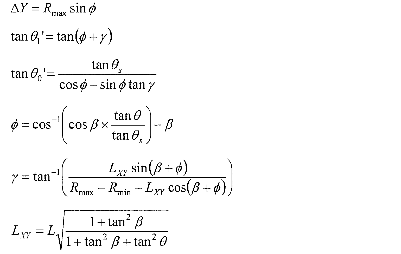
θは、前記第1の傾斜角度であり、
βは、前記第2の傾斜角度である、請求項3に記載の機械部品の製造方法。 - 回転軸線に対して平行な母線によって規定された回転対称面を有する機械部品の製造方法であって、
前記回転軸線をZ軸とし、前記回転対称面の径方向の軸をX軸とし、前記Z軸および前記X軸の両方に直交する軸をY軸とする三次元直交座標系において、直線状の切れ刃を、YZ平面上において0°より大きく90°よりも小さい第1の傾斜角度で前記Z軸に対して傾けられた状態で、切削開始位置に位置付けるステップと、
前記切れ刃の異なる部分が順次接触するように、前記切れ刃を、前記切削開始位置から、回転している前記機械部品に接触させながら送ることによって前記回転対称面を加工するステップとを備え、
前記切削開始位置は、X軸座標およびY軸座標を含み、
前記X軸座標および前記Y軸座標の各々は、前記第1の傾斜角度、および、前記切れ刃がXZ平面上において前記Z軸となす第2の傾斜角度に基づいて定められる、機械部品の製造方法。 - 前記切れ刃の長さ、前記第1の傾斜角度、前記第2の傾斜角度、前記回転対称面の半径、および前記回転対称面のZ軸座標に基づいて、前記切れ刃の軌道を計算するステップをさらに備える、請求項5に記載の機械部品の製造方法。
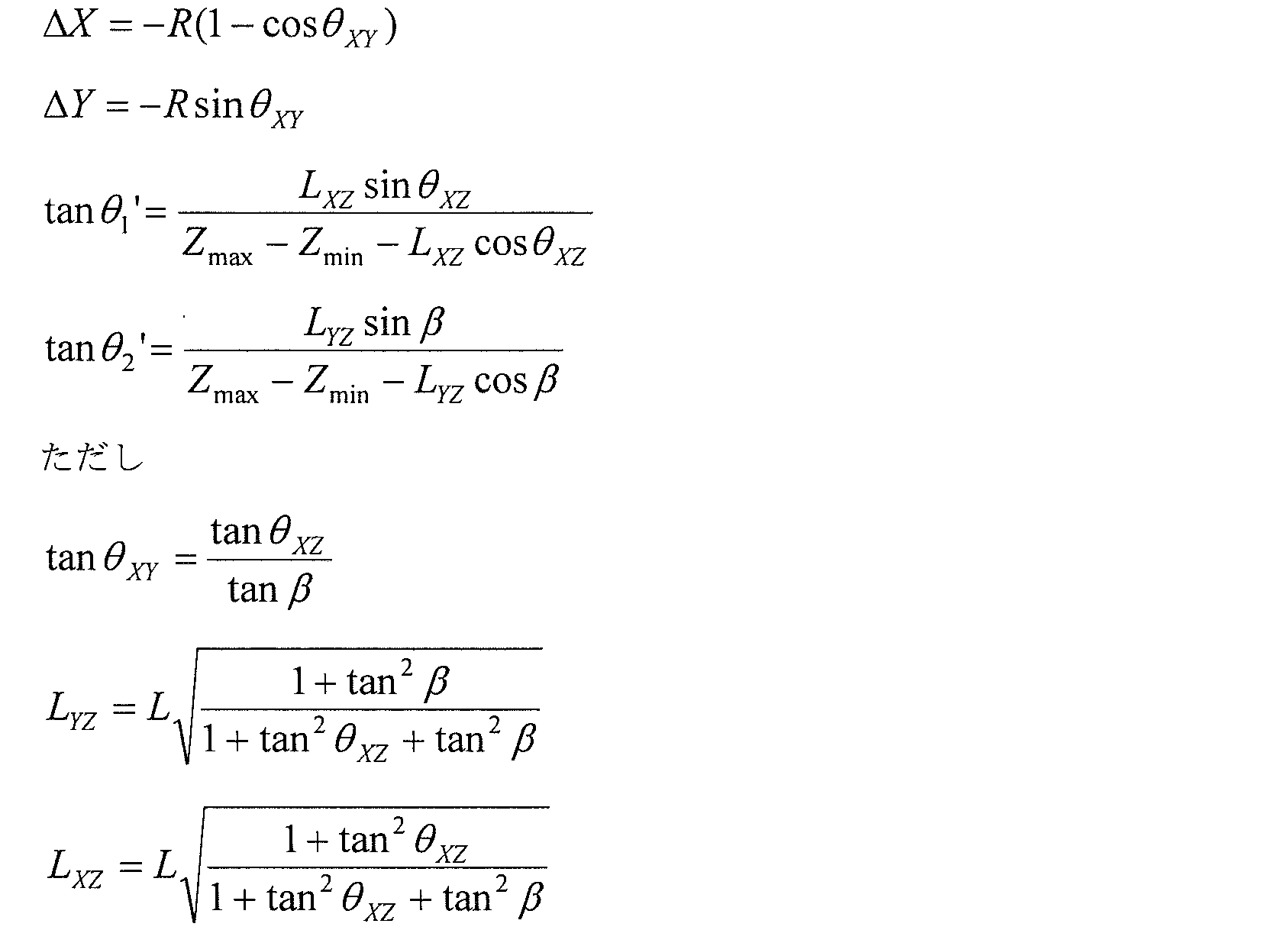
- 前記軌道は、(X,Y,Z)=(R+ΔX-t×tanθ1’,ΔY-t×tanθ2’,Zmin+t)と表現され、
Rは、前記回転対称面の前記半径であり、
tは、0からZmax-Zminまで変化する変数であり、
Zminは、前記回転対称面のZ軸座標の最小値であり、
Zmaxは、前記回転対称面のZ軸座標の最大値であり、
前記第1の傾斜角度をβと表し、前記第2の傾斜角度をθXZと表し、前記切れ刃の長さをLと表すと、ΔX,ΔY,tanθ1’,tanθ2’が以下の式に従う、
- 前記切れ刃は、前記切れ刃の回転を阻止するように構成されたホルダによって保持される、請求項3から請求項7のいずれか1項に記載の機械部品の製造方法。
- 測定器によって前記第1および第2の傾斜角度を測定するステップをさらに備える、請求項3から請求項8のいずれか1項に記載の機械部品の製造方法。
- 請求項1から請求項9のいずれか1項に記載の機械部品の製造方法を実行する、機械部品の製造装置。
- 回転軸線に対して0°より大きく90°より小さい角度で傾斜した稜線によって規定された回転対称面の加工方法であって、
前記回転対称面の前記回転軸線をZ軸とし、前記回転対称面の径方向の軸をX軸とし、前記Z軸および前記X軸の両方に直交する軸をY軸と規定した三次元直交座標系において、前記Z軸に対して0°より大きく90°より小さい角度で傾斜した直線状の切れ刃を、前記X軸上の位置から前記Y軸方向に沿ってずらした切削開始位置に位置決めするステップと、
前記切れ刃を、前記切削開始位置から、X軸成分、Y軸成分およびZ軸成分を有する軌道に沿って、回転している工作物に接触させながら送ることによって前記回転対称面を加工するステップとを備える、回転対称面の加工方法。 - 回転軸線に対して0°より大きく90°より小さい角度で傾斜した稜線によって規定された回転対称面を有する機械部品を製造するためのプログラムを記録した、コンピュータ読み取り可能な記録媒体であって、
前記プログラムが、
前記回転対称面の前記回転軸線をZ軸とし、前記回転対称面の径方向の軸をX軸とし、前記Z軸および前記X軸の両方に直交する軸をY軸と規定した三次元直交座標系において、
直線状の切れ刃の長さ、XZ平面において、前記X軸に対して前記切れ刃がなす第1の傾斜角度、XY平面において、前記X軸に対して前記切れ刃がなす第2の傾斜角度、前記回転対称面の最大半径、前記回転対称面の最小半径、および前記稜線がXZ平面において、X軸に対してなす目標角度を受け付けるステップと、
前記Z軸に対して0°より大きく90°より小さい角度で傾斜した前記切れ刃を、切削開始位置に位置決めするステップと、
前記切れ刃を、前記切削開始位置から軌道に沿って、回転している前記機械部品に接触させながら送ることによって前記回転対称面を加工するステップをコンピュータに実行させ、
前記切削開始位置の座標は、(X,Y,Z)=(Rmax,ΔY,Zmin)と表現され、
前記軌道は、(X,Y,Z)=(Rmax-t,ΔY-t×tanθ1’,Zmin+t×tanθ0’)と表現され、
Rmaxは、前記回転対称面の前記最大半径であり、
Rminは、前記回転対称面の前記最小半径であり、
tは、0からRmax-Rminまで変化する変数であり、
θsは、前記目標角度であり、
ΔY,tanθ1’,tanθ0’が以下の式に従い、

θは、前記第1の傾斜角度であり、
βは、前記第2の傾斜角度である、コンピュータ読み取り可能な記録媒体。 - 回転軸線に対して0°より大きく90°より小さい角度で傾斜した稜線によって規定された回転対称面を有する機械部品を製造するためのプログラムであって、
前記回転対称面の前記回転軸線をZ軸とし、前記回転対称面の径方向の軸をX軸とし、前記Z軸および前記X軸の両方に直交する軸をY軸と規定した三次元直交座標系において、
直線状の切れ刃の長さ、XZ平面において、前記X軸に対して前記切れ刃がなす第1の傾斜角度、XY平面において、前記X軸に対して前記切れ刃がなす第2の傾斜角度、前記回転対称面の最大半径、前記回転対称面の最小半径、および前記稜線がXZ平面において、X軸に対してなす目標角度を受け付けるステップと、
前記Z軸に対して0°より大きく90°より小さい角度で傾斜した前記切れ刃を、切削開始位置に位置決めするステップと、
前記切れ刃を、前記切削開始位置から軌道に沿って、回転している前記機械部品に接触させながら送ることによって前記回転対称面を加工するステップをコンピュータに実行させ、
前記切削開始位置の座標は、(X,Y,Z)=(Rmax,ΔY,Zmin)と表現され、
前記軌道は、(X,Y,Z)=(Rmax-t,ΔY-t×tanθ1’,Zmin+t×tanθ0’)と表現され、
Rmaxは、前記回転対称面の前記最大半径であり、
Rminは、前記回転対称面の前記最小半径であり、
tは、0からRmax-Rminまで変化する変数であり、
θsは、前記目標角度であり、
ΔY,tanθ1’,tanθ0’が以下の式に従い、
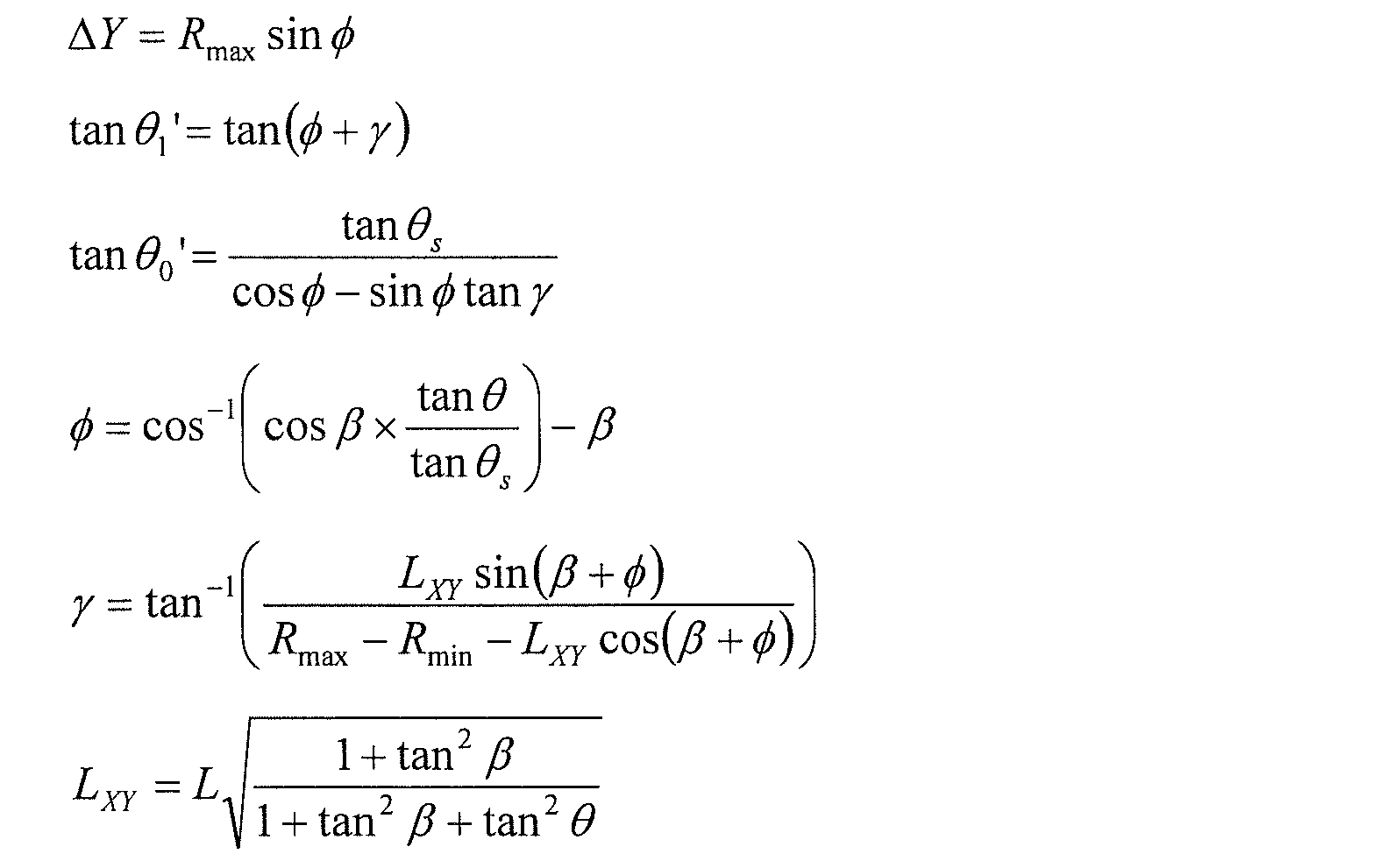
θは、前記第1の傾斜角度であり、
βは、前記第2の傾斜角度である、プログラム。 - 回転軸線に対して平行な母線によって規定された回転対称面の加工方法であって、
前記回転軸線をZ軸とし、前記回転対称面の径方向の軸をX軸とし、前記Z軸および前記X軸の両方に直交する軸をY軸とする三次元直交座標系において、直線状の切れ刃を、YZ平面上において0°より大きく90°よりも小さい第1の傾斜角度で前記Z軸に対して傾けられた状態で、切削開始位置に位置付けるステップと、
前記切れ刃の異なる部分が順次接触するように、前記切れ刃を、前記切削開始位置から、回転している機械部品に接触させながら送ることによって前記回転対称面を加工するステップとを備え、
前記切削開始位置は、X軸座標およびY軸座標を含み、
前記X軸座標および前記Y軸座標の各々は、前記第1の傾斜角度、および、前記切れ刃がXZ平面上において前記Z軸となす第2の傾斜角度に基づいて定められる、回転対称面の加工方法。 - 回転軸線に対して平行な母線によって規定された回転対称面を有する機械部品を製造するためのプログラムを記録した、コンピュータ読み取り可能な記録媒体であって、
前記プログラムが、コンピュータに、
前記回転軸線をZ軸とし、前記回転対称面の径方向の軸をX軸とし、前記Z軸および前記X軸の両方に直交する軸をY軸と規定した三次元直交座標系において、YZ平面において直線状の切れ刃がZ軸に対してなす第1の傾斜角度と、XZ平面において前記切れ刃がZ軸に対してなす第2の傾斜角度と、前記回転対称面の半径と、直線状の切れ刃の長さとを受け付けるステップと、
前記切れ刃を、切削開始位置に位置付けるステップと、
前記切れ刃を、回転している前記機械部品に接触させながら、前記切削開始位置から軌道に沿って送ることによって前記回転対称面を加工するステップとを実行させ、
前記軌道は、(X,Y,Z)=(R+ΔX-t×tanθ1’,ΔY-t×tanθ2’,Zmin+t)と表現され、
Rは、前記回転対称面の前記半径であり、
tは、0からZmax-Zminまで変化する変数であり、
Zminは、前記回転対称面のZ軸座標の最小値であり、
Zmaxは、前記回転対称面のZ軸座標の最大値であり、
前記第1の傾斜角度をβと表し、前記第2の傾斜角度をθXZと表し、前記切れ刃の長さをLと表すと、ΔX,ΔY,tanθ1’,tanθ2’が以下の式に従う、

- 回転軸線に対して平行な母線によって規定された回転対称面を有する機械部品を製造するためのプログラムであって、
前記プログラムが、コンピュータに、
前記回転対称面の前記回転軸線をZ軸とし、前記回転対称面の径方向の軸をX軸とし、前記Z軸および前記X軸の両方に直交する軸をY軸と規定した三次元直交座標系において、YZ平面において直線状の切れ刃がZ軸に対してなす第1の傾斜角度と、XZ平面において前記切れ刃がZ軸に対してなす第2の傾斜角度と、前記回転対称面の半径と、前記切れ刃の長さとを受け付けるステップと、
前記切れ刃を、切削開始位置に位置付けるステップと、
前記切れ刃を、回転している前記機械部品に接触させながら、前記切削開始位置から軌道に沿って送ることによって前記回転対称面を加工するステップとを実行させ、
前記軌道は、(X,Y,Z)=(R+ΔX-t×tanθ1’,ΔY-t×tanθ2’,Zmin+t)と表現され、
Rは、前記回転対称面の前記半径であり、
tは、0からZmax-Zminまで変化する変数であり、
Zminは、前記回転対称面のZ軸座標の最小値であり、
Zmaxは、前記回転対称面のZ軸座標の最大値であり、
前記第1の傾斜角度をβと表し、前記第2の傾斜角度をθXZと表し、前記切れ刃の長さをLと表すと、ΔX,ΔY,tanθ1’,tanθ2’が以下の式に従う、
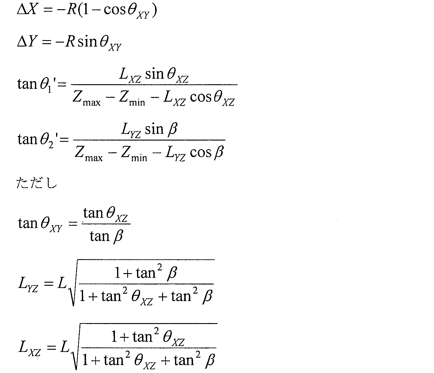
Priority Applications (7)
| Application Number | Priority Date | Filing Date | Title |
|---|---|---|---|
| CN201580073481.1A CN107111301B (zh) | 2015-01-16 | 2015-12-16 | 机器部件的制造方法、机器部件的制造装置、旋转对称面的加工方法、记录介质 |
| EP15878009.8A EP3246774B1 (en) | 2015-01-16 | 2015-12-16 | Method for manufacturing machine part, apparatus for manufacturing machine part, machining method for rotationally symmetric surface, recording medium, and program |
| US15/542,185 US10343220B2 (en) | 2015-01-16 | 2015-12-16 | Method for manufacturing machine component, apparatus for manufacturing machine component, method for machining rotation symmetry plane, recording medium, and program |
| MX2017009143A MX2017009143A (es) | 2015-01-16 | 2015-12-16 | Metodo para fabricar partes de maquinas, aparato para fabricar partes de maquinas, metodo de maquinado para superficie rotacionalmente simetrica, medio de grabacion y programa. |
| BR112017014471-9A BR112017014471A2 (ja) | 2015-01-16 | 2015-12-16 | A manufacturing method of a machine part, a manufacture device of a machine part, a processing method of a rotation symmetry side, a recording medium, and a program |
| KR1020177021809A KR20170103871A (ko) | 2015-01-16 | 2015-12-16 | 기계 부품의 제조 방법, 기계 부품의 제조 장치, 회전 대칭면의 가공 방법, 기록 매체 및 프로그램 |
| US16/417,169 US10960471B2 (en) | 2015-01-16 | 2019-05-20 | Method for manufacturing machine component, apparatus for manufacturing machine component, method for machining rotation symmetry plane, recording medium, and program |
Applications Claiming Priority (4)
| Application Number | Priority Date | Filing Date | Title |
|---|---|---|---|
| JP2015007115A JP6175082B2 (ja) | 2015-01-16 | 2015-01-16 | 機械部品の製造方法、機械部品の製造装置、回転対称面の加工方法、記録媒体およびプログラム |
| JP2015-007115 | 2015-01-16 | ||
| JP2015090385A JP6175096B2 (ja) | 2015-04-27 | 2015-04-27 | 機械部品の製造方法、機械部品の製造装置、回転対称面の加工方法、記録媒体およびプログラム |
| JP2015-090385 | 2015-04-27 |
Related Child Applications (2)
| Application Number | Title | Priority Date | Filing Date |
|---|---|---|---|
| US15/542,185 A-371-Of-International US10343220B2 (en) | 2015-01-16 | 2015-12-16 | Method for manufacturing machine component, apparatus for manufacturing machine component, method for machining rotation symmetry plane, recording medium, and program |
| US16/417,169 Division US10960471B2 (en) | 2015-01-16 | 2019-05-20 | Method for manufacturing machine component, apparatus for manufacturing machine component, method for machining rotation symmetry plane, recording medium, and program |
Publications (1)
| Publication Number | Publication Date |
|---|---|
| WO2016114058A1 true WO2016114058A1 (ja) | 2016-07-21 |
Family
ID=56405613
Family Applications (1)
| Application Number | Title | Priority Date | Filing Date |
|---|---|---|---|
| PCT/JP2015/085197 Ceased WO2016114058A1 (ja) | 2015-01-16 | 2015-12-16 | 機械部品の製造方法、機械部品の製造装置、回転対称面の加工方法、記録媒体およびプログラム |
Country Status (7)
| Country | Link |
|---|---|
| US (2) | US10343220B2 (ja) |
| EP (1) | EP3246774B1 (ja) |
| KR (1) | KR20170103871A (ja) |
| CN (1) | CN107111301B (ja) |
| BR (1) | BR112017014471A2 (ja) |
| MX (1) | MX2017009143A (ja) |
| WO (1) | WO2016114058A1 (ja) |
Families Citing this family (6)
| Publication number | Priority date | Publication date | Assignee | Title |
|---|---|---|---|---|
| JP6679599B2 (ja) | 2015-09-09 | 2020-04-15 | 住友電工ハードメタル株式会社 | 機械部品の製造方法、機械部品の製造装置、回転対称面の加工方法、記録媒体およびプログラム |
| CN108778579B (zh) | 2016-03-04 | 2020-07-14 | 住友电工硬质合金株式会社 | 用于制造机器部件的方法、用于制造机器部件的设备、用于加工旋转对称面的方法、记录介质和程序 |
| JP6828336B2 (ja) * | 2016-09-16 | 2021-02-10 | 株式会社ジェイテクト | 加工方法 |
| EP4380745A4 (en) * | 2021-08-04 | 2025-08-27 | Celeritive Tech Inc | METHODS FOR PREVENTING NOTCH FORMATION IN, AND/OR EXTENDING THE USEFUL LIFE OF, CUTTING TOOLS FOR TURNING, AND RELATED SYSTEMS |
| WO2024016354A1 (en) * | 2022-07-22 | 2024-01-25 | Abb Schweiz Ag | Method for adjusting robot path, computing device, and computer readable storage medium |
| CN116787220B (zh) * | 2023-08-09 | 2025-06-20 | 重庆齿轮箱有限责任公司 | 一种锁紧盘加工方法 |
Citations (2)
| Publication number | Priority date | Publication date | Assignee | Title |
|---|---|---|---|---|
| JPH02156308A (ja) * | 1988-12-08 | 1990-06-15 | Fanuc Ltd | 数値制御装置 |
| WO2013088884A1 (ja) * | 2011-12-13 | 2013-06-20 | 村田機械株式会社 | 工作機械 |
Family Cites Families (8)
| Publication number | Priority date | Publication date | Assignee | Title |
|---|---|---|---|---|
| EP1253988B1 (de) | 1999-12-17 | 2003-07-02 | BOEHRINGER WERKZEUGMASCHINEN GmbH | Verfahren zur drallfreien spanenden bearbeitung von rotationssymmetrischen flächen |
| DE10144649C5 (de) | 2001-09-11 | 2008-11-13 | Boehringer Werkzeugmaschinen Gmbh | Verfahren zur drallfreien spanenden Bearbeitung von rotationssymmetrischen Flächen |
| JP4169723B2 (ja) * | 2004-02-20 | 2008-10-22 | 松下電工株式会社 | 面材の開口部の形成方法 |
| DE102007033820C5 (de) * | 2007-07-18 | 2017-12-14 | Emag Holding Gmbh | Verfahren zur Bearbeitung rotierender Werkstücke |
| CN101391322B (zh) * | 2008-10-30 | 2010-11-24 | 吉林大学 | 球面渐开线齿形弧齿锥齿轮切齿法与机床 |
| DE202010009081U1 (de) * | 2010-06-15 | 2011-10-28 | J.G. WEISSER SöHNE GMBH & CO. KG | Vorrichtung zum spanenden Drehbearbeiten |
| JP5761577B2 (ja) * | 2012-06-22 | 2015-08-12 | アイシン精機株式会社 | クラウンギヤの製造装置及び製造方法 |
| JP6428919B2 (ja) * | 2015-03-25 | 2018-11-28 | アイシン機工株式会社 | 切削工具、スカイビング加工装置および方法 |
-
2015
- 2015-12-16 KR KR1020177021809A patent/KR20170103871A/ko not_active Withdrawn
- 2015-12-16 CN CN201580073481.1A patent/CN107111301B/zh active Active
- 2015-12-16 WO PCT/JP2015/085197 patent/WO2016114058A1/ja not_active Ceased
- 2015-12-16 EP EP15878009.8A patent/EP3246774B1/en active Active
- 2015-12-16 MX MX2017009143A patent/MX2017009143A/es unknown
- 2015-12-16 US US15/542,185 patent/US10343220B2/en active Active
- 2015-12-16 BR BR112017014471-9A patent/BR112017014471A2/ja not_active Application Discontinuation
-
2019
- 2019-05-20 US US16/417,169 patent/US10960471B2/en active Active
Patent Citations (2)
| Publication number | Priority date | Publication date | Assignee | Title |
|---|---|---|---|---|
| JPH02156308A (ja) * | 1988-12-08 | 1990-06-15 | Fanuc Ltd | 数値制御装置 |
| WO2013088884A1 (ja) * | 2011-12-13 | 2013-06-20 | 村田機械株式会社 | 工作機械 |
Non-Patent Citations (1)
| Title |
|---|
| See also references of EP3246774A4 * |
Also Published As
| Publication number | Publication date |
|---|---|
| EP3246774A4 (en) | 2018-09-26 |
| CN107111301A (zh) | 2017-08-29 |
| EP3246774B1 (en) | 2022-07-20 |
| MX2017009143A (es) | 2018-05-07 |
| US10960471B2 (en) | 2021-03-30 |
| US10343220B2 (en) | 2019-07-09 |
| BR112017014471A2 (ja) | 2018-01-16 |
| EP3246774A1 (en) | 2017-11-22 |
| CN107111301B (zh) | 2019-11-08 |
| KR20170103871A (ko) | 2017-09-13 |
| US20190270141A1 (en) | 2019-09-05 |
| US20180257145A1 (en) | 2018-09-13 |
Similar Documents
| Publication | Publication Date | Title |
|---|---|---|
| US12117794B2 (en) | Method for processing workpiece and machine for processing workpiece | |
| CN107111301B (zh) | 机器部件的制造方法、机器部件的制造装置、旋转对称面的加工方法、记录介质 | |
| KR20170138440A (ko) | 재료를 제거하는 것에 의해 공구를 가공하기 위한 방법 및 디바이스 | |
| US11940773B2 (en) | Workpiece processing method and workpiece processing machine | |
| US12422814B2 (en) | Workpiece machining method and workpiece machining device | |
| WO2016152396A1 (ja) | 切削工具、スカイビング加工装置および方法 | |
| JP6734361B2 (ja) | 機械部品の製造方法、機械部品の製造装置、回転対称面の加工方法、記録媒体およびプログラム | |
| EP3348339B1 (en) | Method for manufacturing machine part | |
| JP6838056B2 (ja) | 切れ刃の軌道を補正する方法、記録媒体およびプログラム | |
| JP6175082B2 (ja) | 機械部品の製造方法、機械部品の製造装置、回転対称面の加工方法、記録媒体およびプログラム | |
| JP6175096B2 (ja) | 機械部品の製造方法、機械部品の製造装置、回転対称面の加工方法、記録媒体およびプログラム | |
| JP2016118928A (ja) | 加工方法、アライメントマーク部品、および部品の製造方法 | |
| JP2000246589A (ja) | 自由曲面加工方法 | |
| JP2010110827A (ja) | レンズ型の加工装置、レンズ型の加工装置に用いる加工具、レンズ型の加工装置を用いた加工方法、レンズ型及びレンズ |
Legal Events
| Date | Code | Title | Description |
|---|---|---|---|
| 121 | Ep: the epo has been informed by wipo that ep was designated in this application |
Ref document number: 15878009 Country of ref document: EP Kind code of ref document: A1 |
|
| REEP | Request for entry into the european phase |
Ref document number: 2015878009 Country of ref document: EP |
|
| WWE | Wipo information: entry into national phase |
Ref document number: 15542185 Country of ref document: US |
|
| WWE | Wipo information: entry into national phase |
Ref document number: MX/A/2017/009143 Country of ref document: MX |
|
| NENP | Non-entry into the national phase |
Ref country code: DE |
|
| REG | Reference to national code |
Ref country code: BR Ref legal event code: B01A Ref document number: 112017014471 Country of ref document: BR |
|
| ENP | Entry into the national phase |
Ref document number: 20177021809 Country of ref document: KR Kind code of ref document: A |
|
| ENP | Entry into the national phase |
Ref document number: 112017014471 Country of ref document: BR Kind code of ref document: A2 Effective date: 20170704 |