WO2016121475A1 - 燃料噴射弁 - Google Patents
燃料噴射弁 Download PDFInfo
- Publication number
- WO2016121475A1 WO2016121475A1 PCT/JP2016/050607 JP2016050607W WO2016121475A1 WO 2016121475 A1 WO2016121475 A1 WO 2016121475A1 JP 2016050607 W JP2016050607 W JP 2016050607W WO 2016121475 A1 WO2016121475 A1 WO 2016121475A1
- Authority
- WO
- WIPO (PCT)
- Prior art keywords
- valve
- valve body
- seat
- fuel injection
- fuel
- Prior art date
- Legal status (The legal status is an assumption and is not a legal conclusion. Google has not performed a legal analysis and makes no representation as to the accuracy of the status listed.)
- Ceased
Links
Images




Classifications
-
- F—MECHANICAL ENGINEERING; LIGHTING; HEATING; WEAPONS; BLASTING
- F02—COMBUSTION ENGINES; HOT-GAS OR COMBUSTION-PRODUCT ENGINE PLANTS
- F02M—SUPPLYING COMBUSTION ENGINES IN GENERAL WITH COMBUSTIBLE MIXTURES OR CONSTITUENTS THEREOF
- F02M61/00—Fuel-injectors not provided for in groups F02M39/00 - F02M57/00 or F02M67/00
- F02M61/16—Details not provided for in, or of interest apart from, the apparatus of groups F02M61/02 - F02M61/14
- F02M61/18—Injection nozzles, e.g. having valve seats; Details of valve member seated ends, not otherwise provided for
-
- F—MECHANICAL ENGINEERING; LIGHTING; HEATING; WEAPONS; BLASTING
- F02—COMBUSTION ENGINES; HOT-GAS OR COMBUSTION-PRODUCT ENGINE PLANTS
- F02M—SUPPLYING COMBUSTION ENGINES IN GENERAL WITH COMBUSTIBLE MIXTURES OR CONSTITUENTS THEREOF
- F02M61/00—Fuel-injectors not provided for in groups F02M39/00 - F02M57/00 or F02M67/00
- F02M61/16—Details not provided for in, or of interest apart from, the apparatus of groups F02M61/02 - F02M61/14
- F02M61/18—Injection nozzles, e.g. having valve seats; Details of valve member seated ends, not otherwise provided for
- F02M61/188—Spherical or partly spherical shaped valve member ends
-
- F—MECHANICAL ENGINEERING; LIGHTING; HEATING; WEAPONS; BLASTING
- F16—ENGINEERING ELEMENTS AND UNITS; GENERAL MEASURES FOR PRODUCING AND MAINTAINING EFFECTIVE FUNCTIONING OF MACHINES OR INSTALLATIONS; THERMAL INSULATION IN GENERAL
- F16K—VALVES; TAPS; COCKS; ACTUATING-FLOATS; DEVICES FOR VENTING OR AERATING
- F16K1/00—Lift valves or globe valves, i.e. cut-off apparatus with closure members having at least a component of their opening and closing motion perpendicular to the closing faces
- F16K1/32—Details
- F16K1/34—Cutting-off parts, e.g. valve members, seats
- F16K1/42—Valve seats
- F16K1/427—Attachment of the seat to the housing by one or more additional fixing elements
Definitions
- the present invention relates to a fuel injection valve used for an internal combustion engine.
- a valve body including a ball valve that opens and closes an injection hole is slidably incorporated in the injection valve body, and the injection valve body, the valve body,
- the upper and lower valve guides comprising a guide surface on the injection valve body side and a sliding surface on the valve body side that slides on the guide surface, and a stopper on the injection valve body side and the stopper open to the stopper.
- the upper and lower valve guide portions are formed so that the upper and lower sliding surfaces on the valve body side are substantially spherical. Discloses a fuel injection valve in which the clearance between the guide surface and the sliding surface is set so as to have a precise fitting state with no looseness.
- the spherical sliding surface of the guide ring that constitutes the valve body with respect to the smooth guide surface of the core Contact.
- the sliding surface of the guide ring is a spherical surface that does not twist
- the guide ring constituting the valve body is held in a state that is easy to slide in the axial direction. Is done. For this reason, wear hardly occurs between the guide surface of the core and the sliding surface of the guide ring, and it is possible to suppress the sliding resistance of the valve body from changing with time. Therefore, the speed at which the ball valve, which is a constituent member of the valve body, opens and closes the fuel injection hole hardly fluctuates, and the change with time of the fuel injection amount can be suppressed.
- the fuel injection valve 1 is composed of a nozzle body 2, and a valve needle 3 is disposed on the nozzle body 1.
- the valve needle 3 is operatively connected to a valve closing body 4, and the valve closing body 4 forms a seal seat in cooperation with a valve seat surface 6 disposed on the valve seat body 5.
- the fuel injection valve 1 of the illustrated embodiment is a fuel injection valve 1 that is provided with at least one injection opening 7 and can be opened inward.
- the valve closing body 4 of the fuel injection valve 1 formed according to the present invention is disclosed as having a substantially spherical shape.
- the tip of the valve body has a spherical shape, and a guide portion with a nozzle cup and a seat portion are formed.
- the relationship between the radius of curvature of the guide portion and the valve seat portion and the position of the center of curvature are not described.
- the usual maximum fuel pressure may increase to about 35MP.
- the fuel injection valve is required to operate up to 45 MPa, for example. Then, depending on the seat diameter, the fluid force may exceed the valve opening force, and the needle valve may not be kept open when necessary, and may close.
- a fuel injection valve includes a valve seat, a valve body that is seated on or separated from the valve seat, and an injection formed downstream of the valve seat.
- a guide portion that is formed on the upstream side of the valve seat portion on which the valve seat portion of the valve body is seated and that guides a guided portion on the downstream side of the valve body, the guide portion
- the size in the intersecting direction of the valve seat part is 0.4 to 0.8 times the size in the intersecting direction intersecting the axial direction.
- the fuel injection valve when the normal maximum fuel pressure is 35 MPa, even if the fuel injection valve is required to operate up to 45 MPa, for example, the fluid force does not exceed the valve opening force, and when necessary, the needle valve It is possible to provide a fuel injection valve that can maintain the valve opening.
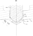
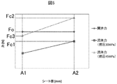
- FIG. 1 is an overall cross-sectional view of a fuel injection valve according to an embodiment of the present invention. It is an expanded sectional view of the tip part of a fuel injection valve by an embodiment of the present invention. It is an expanded sectional view of the tip part of a fuel injection valve by an embodiment of the present invention. It is an expanded sectional view of the tip part of a fuel injection valve by an embodiment of the present invention. It is the graph which showed the relationship between the seat diameter of the valve body and the fluid force. It is a cross-sectional view of the front-end
- the internal combustion engine is provided with a fuel injection control device that performs a calculation to convert an appropriate amount of fuel according to the operating state into an injection time of the fuel injection valve and drives the fuel injection valve that supplies the fuel.
- the fuel injection valve includes, for example, a mover having a cylindrical mover and a needle valve positioned at the center of the mover, and a stator having a fuel introduction hole for guiding fuel to the center.
- a gap is provided between the end face and the end face of the mover, and an electromagnetic solenoid that supplies magnetic flux to a magnetic path including the gap is provided.
- the mover is driven by the magnetic attraction generated between the end face of the mover and the end face of the stator by the magnetic flux passing through the gap to drive the mover, and the needle valve disc is pulled away from the valve seat.
- the fuel passage provided in the valve seat is configured to open.
- the amount of fuel to be injected is determined mainly by the pressure difference between the fuel pressure and the atmospheric pressure at the injection port of the fuel injection valve, and the time during which fuel is injected while the valve body is kept open.
- Fuel injection valves are required to have zero fuel leakage over the life of the product, and in order to reduce the amount of fuel leakage from the tip of the fuel injection valve, the part where the valve body and valve seat abut is In both cases, for example, a shape accuracy of 1 ⁇ m or less is required.
- the fuel injection valve accurately supplies a very small amount of fuel, for example 1 to 2 mg per injection, in a predetermined fuel spray shape. It is required to spray.
- the clearance between the valve body and the guide member for guiding the valve body provided upstream of the valve seat is only about several ⁇ m, for example.
- the fuel injection pressure is increased from the conventional 20 MPa to, for example, about 35 MPa to reduce the droplet size of the injected fuel and vaporize it. Attempts have been made to promote.
- the fuel injection valve of the present embodiment has a different radius of curvature between the guide part of the valve body and the seat part, and by matching the curvature centers of the guide part of the valve body and the seat part, the diameter of the guide part is increased.
- the diameter of the seat part can be designed freely without depending on it.
- the radius of curvature of the seat portion can be independently reduced with respect to the guide portion of the valve body with respect to the increase in fuel pressure, and the force generated by the pressure difference of the fluid generated in the seat portion is reduced.
- the valve body can be opened and held at a high fuel pressure.
- FIG. 1 is a longitudinal sectional view of a fuel injection valve according to the present embodiment.
- FIG. 2 to 5 are partial enlarged views centering on the nozzle hole cup 116 and the valve body tip 114B of FIG. 1, and are shown in a simplified form, limited to the parts that are characteristic of the fuel injection valve in this embodiment. It is a thing.
- FIG. 2 to FIG. 5 the size of parts and the size of the gap are exaggerated from the actual ratio for easy understanding of the operation and function, and unnecessary parts are omitted for explaining the function.
- the same constituent elements are given the same reference numerals, and redundant descriptions are omitted.
- the nozzle hole cup support 101 includes a small diameter cylindrical portion 22 having a small diameter and a large diameter cylindrical portion 23 having a large diameter.
- An injection hole cup (fuel injection hole forming member) 116 having a guide part 115 and a fuel injection hole 117 is inserted or press-fitted into the distal end portion of the small diameter cylindrical part 22, and the outer periphery of the front end surface of the injection hole cup 116 is inserted.
- the edge is fixed to the small-diameter cylindrical portion 22 by being welded all around.
- the guide portion 115 has a function of guiding the outer periphery when a needle valve 114A provided at the tip of a needle valve 114A constituting a mover described later moves up and down in the axial direction of the fuel injection valve.
- a conical valve seat portion 39 is formed in the nozzle hole cup 116 on the downstream side of the guide portion 115.
- a needle valve 114A provided at the tip of the needle valve 114A comes into contact with or separates from the valve seat sheet portion 39, thereby blocking the flow of fuel or guiding it to the fuel injection hole.
- a groove is formed on the outer periphery of the nozzle hole cup support 101, and a combustion gas seal member typified by a resin-made chip seal 131 is fitted into the groove.
- a needle valve guide member 113 that guides a needle valve 114A that constitutes a mover is press-fitted into the drawing portion 25 of the large-diameter cylindrical portion 23 at the inner peripheral lower end of the large-diameter cylindrical portion 23 of the nozzle hole cup support 101. It is fixed.
- the needle valve guide member 113 is provided with a guide portion 127 for guiding the needle valve 114A in the axial direction at the center, and a plurality of fuel passages 126 are perforated around the guide portion.
- the elongated needle valve 114A has a radial position defined by the guide portion 127 of the needle valve guide member 113, and is guided to reciprocate straight in the axial direction. Note that the valve opening direction is an upward direction of the valve shaft, and the valve closing direction is a downward direction of the valve shaft direction.
- a head 114C having a stepped portion 129 having an outer diameter larger than the diameter of the needle valve 114A is provided at the end opposite to the end where the valve body tip 114B of the needle valve 114A is provided.
- the upper surface of the stepped portion 129 is provided with a seating surface for the spring 110 that urges the needle valve 114A in the valve closing direction, and holds the spring 110 together with the head portion 114C.
- the mover has a mover 102 with a through hole 128 through which the needle valve 114A passes.
- a zero spring 112 that biases the mover 102 in the valve opening direction is held between the mover 102 and the needle valve guide member 113.
- the diameter of the through hole 128 is smaller than the diameter of the stepped portion 129 of the head portion 114C, under the biasing force of the spring 110 or the action of gravity that presses the needle valve 114A toward the valve seat of the nozzle hole cup 116.
- the upper surface of the movable element 102 held by the zero spring 112 is in contact with the lower end surface of the stepped portion 129 of the needle valve 114A, and both are engaged.
- the two cooperate in response to the upward movement of the mover 102 against the urging force or gravity of the zero spring 112 or the downward movement of the needle valve 114A along the urging force of the zero spring 112 or gravity. It will move.
- the force for moving the needle valve 114A upward or the force for moving the mover 102 downward acts independently of each other regardless of the biasing force or gravity of the zero spring 112, they may move in different directions. it can.
- the fixed core 107 is press-fitted into the inner peripheral portion of the large-diameter cylindrical portion 23 of the nozzle hole cup support 101 and is welded and joined at the press-fit contact position. A gap formed between the inside of the large-diameter cylindrical portion 23 of the nozzle hole cup support 101 and the outside air is sealed by this welding joint.
- a through hole 107D having a diameter slightly larger than the diameter of the stepped portion 129 of the needle valve 114A is provided as a fuel introduction passage.
- the lower end surface of the fixed core 107, the upper end surface of the movable element 102, and the collision end surface are plated to improve durability. Even when relatively soft soft magnetic stainless steel is used for the mover, durability reliability can be ensured by using hard chrome plating or electroless nickel plating.
- the lower end of the spring 110 for setting the initial load is in contact with the spring receiving surface formed on the upper end surface of the stepped portion 129 provided on the head portion 114C of the needle valve 114A, and the other end of the spring 110 is the fixed core.
- the spring 110 is held between the head 114 ⁇ / b> C and the adjuster 54 by being received by the adjuster 54 press-fitted into the through hole 107 ⁇ / b> D of the 107.
- a cup-shaped housing 103 is fixed to the outer periphery of the large-diameter cylindrical portion 23 of the nozzle hole cup support 101.
- a through hole is provided at the center of the bottom of the housing 103, and the large-diameter cylindrical portion 23 of the nozzle hole cup support 101 is inserted through the through hole.
- a portion of the outer peripheral wall of the housing 103 forms an outer peripheral yoke portion facing the outer peripheral surface of the large-diameter cylindrical portion 23 of the nozzle hole cup support 101.
- An electromagnetic coil 105 wound in an annular shape is arranged in a cylindrical space formed by the housing 103.
- the coil 105 is formed of an annular coil bobbin 104 having a U-shaped groove that opens radially outward, and a copper wire wound in the groove.
- a rigid conductor 109 is fixed at the beginning and end of winding of the coil 105, and is drawn out from a through hole provided in the fixed core 107.
- the outer periphery of the large diameter cylindrical portion 23 of the conductor 109, the fixed core 107, and the nozzle hole cup support body 101 is molded by injecting an insulating resin from the inner periphery of the upper end opening of the housing 103, and is covered with the resin molded body 121.
- a toroidal magnetic path is formed around the electromagnetic coils (104, 105).
- a plug for supplying power from a high-voltage power source and a battery power source is connected to the connector 43A formed at the tip of the conductor 109, and energization and de-energization are controlled by a controller (not shown). While the coil 105 is energized, a magnetic attractive force is generated between the movable element 102 of the movable element 114 and the fixed core 107 in the magnetic attractive gap by the magnetic flux passing through the magnetic circuit 140, and the movable element 102 applies the set load of the spring 110. It moves upward by being sucked with a force exceeding it.
- the mover 102 engages with the needle valve head 114 ⁇ / b> C, moves upward together with the needle valve 114 ⁇ / b> A, and moves until the upper end surface of the mover 102 collides with the lower end surface of the fixed core 107.
- the valve body tip 114B at the tip of the needle valve 114A is separated from the valve seat portion 39, and the fuel passes through the fuel passage 118 and is ejected from the injection hole 117 at the tip of the injection hole cup 116 into the combustion chamber of the internal combustion engine. To do.
- valve body tip 114B at the tip of the needle valve 114A is separated from the valve seat portion 39 and pulled upward, the elongated needle valve 114A is connected to the guide 127 of the needle valve guide member 113 and the nozzle hole cup. It is guided by the two guide portions 115 of 116 so as to return straight along the valve shaft direction.
- valve body distal end portion 114B at the distal end of the needle valve 114A is in contact with the valve seat portion 39 and is in the closed position, the elongated needle valve 114A is guided only by the guide portion 127 of the needle valve guide member 113, The guide part 115 of the nozzle hole cup 116 is not in contact.
- the stepped portion 129 of the head portion 114C comes into contact with the upper surface of the movable element 102 and moves the movable element 102 to the needle valve guide member 113 side by overcoming the force of the zero spring 112.
- the mover 102 is separate from the needle valve 114A, and therefore continues to move in the direction of the needle valve guide member 113 due to inertial force.
- friction due to fluid is generated between the outer periphery of the needle valve 114A and the inner periphery of the mover 102, and the energy of the needle valve 114A that rebounds from the valve seat sheet portion 39 in the valve opening direction again is absorbed.
- the movable element 102 having a large inertial mass is separated from the needle valve 114A, the rebound energy itself is reduced. Further, since the inertial force of the movable element 102 that has absorbed the rebound energy of the needle valve 114A is reduced by that amount and the repulsive force received after the zero spring 112 is compressed is also reduced, the needle valve is caused by the rebounding phenomenon of the movable element 102 itself. The phenomenon that 114A is moved again in the valve opening direction is less likely to occur. Thus, the rebound of the needle valve 114A is minimized, and the so-called secondary injection phenomenon in which the valve is opened after the energization of the electromagnetic coils (104, 105) is cut off and the fuel is injected randomly is suppressed.
- the inertial force of the movable element 102 that has absorbed the rebound energy of the needle valve 114A is reduced by that amount and the repulsive force received after the zero spring 112 is compressed is also reduced, the needle valve is caused by the rebounding phenomenon of the
- FIG. 2 is an enlarged cross-sectional view of the tip of the fuel injection valve when the needle valve 114A is in a closed state.
- the guided portion 201 of the valve body tip portion 114B and the guide portion 202 of the nozzle hole cup 116, and the diameter of the valve body tip portion 114B when the mover shown in FIG. Define the position of the direction.
- the shape of the guided portion 201 of the valve body tip portion 114B is a part of a spherical surface having a diameter ⁇ D.
- the shape of the valve body sheet portion 203 of the valve body front end portion 114B contacting the valve seat sheet portion 39 of the nozzle hole cup 116 is a part of a spherical surface having a diameter ⁇ S.
- FIG. 3 is an enlarged cross-sectional view of the tip of the fuel injection valve when the needle valve 114A is in the open state.
- the upstream portion 401 of the nozzle hole cup 116 is filled with high-pressure (for example, 20 MPa) fuel.
- a gap 402 exists between the valve seat sheet portion 39 of the nozzle hole cup 116 and the valve body seat portion 203 of the valve body tip portion 114B.
- the outside 403 of the nozzle hole cup 116 is the pressure in the cylinder of the internal combustion engine, and is about 0.1 MPa, for example. Due to the pressure difference between the upstream portion 401 and the outside 403, the fuel in the fuel injection valve flows from the gap 402 to the nozzle hole 117 at a higher flow rate and flows out to the outside 403.
- the fuel pressure is significantly smaller in the region downstream of the seat diameter ⁇ A of the valve body tip portion 114B, and the needle valve 114A has an area of the seat diameter ⁇ A, and the upstream portion 401 and the seat.
- a force (hereinafter referred to as fluid force) multiplied by the fuel pressure difference in the region downstream from the diameter ⁇ A is applied in the downstream direction of FIG.
- FIG. 6 shows a cross-sectional view of the tip portion of the fuel injection valve.
- the fuel that flows in the vicinity of the valve body front end portion 114B flows through the outer peripheral flow path 500 and flows downstream of the valve body front end portion 114B.
- the outer circumferential side channel 500 is located at a position corresponding to the guided portion 201 of the valve body distal end portion 114B in the axial direction, and is formed to be recessed toward the inner circumferential side. Further, the outer peripheral channel 500 is formed between adjacent guided portions 201.
- FIG. 5 shows the fluid force generated when the valve element is opened with respect to the diameter ⁇ A of the valve element seat portion 203 of the needle valve 114A.
- the fuel injection valve is required to operate up to, for example, 30 MPa.
- the seat diameter is ⁇ A2
- the fluid force is Fc1
- the coil 105 of the fuel injection valve in FIG. 1 is energized, the spring 110 is driven by the force that the fixed core 107 attracts the mover 102 (hereinafter referred to as magnetic attraction force). Therefore, the needle valve 114A can keep the valve open.
- the usual maximum fuel pressure may increase to about 35MP.
- the fuel injection valve is required to operate up to 45 MPa, for example.
- the seat diameter is ⁇ A2
- the fluid force is Fc2, which exceeds the valve opening force Fo. Therefore, the needle valve 114A cannot be kept open and closes.
- the fuel injection valve includes a valve seat 114 and a valve body 114 that is seated or separated from the valve seat 39, and an injection hole 117 that is formed on the downstream side of the valve seat 39. And a guide portion 202 that is formed on the upstream side of the valve seat seat portion 39 valve on which the valve body seat portion 203 of the valve body 114 is seated and guides the guided portion 201 on the downstream side of the valve body 114. And the size of the crossing direction of the valve seat part 39 is formed to be 0.4 to 0.8 times the size of the crossing direction crossing the axial direction of the guide portion 202. To do.
- the present inventors set the size of the crossing direction intersecting the axial direction of the guide portion 202, that is, the diameter ⁇ G to 2 mm, and the size of the valve seat portion 39 in the crossing direction, In other words, it has been found that by setting the diameter ⁇ A to 1.6 mm or less, the needle valve 114A can be kept open even when the maximum fuel pressure is about 35 MP.
- the diameter ⁇ A is 0.8 mm or less
- the contact area between the valve seat 203 and the valve seat 39 becomes small, and the contact pressure becomes large.
- the contact pressure is large, a material having high strength is required for the valve body seat portion 203 and the valve seat portion 39, which is not preferable from the viewpoint of manufacturing the fuel injection valve as inexpensively as possible.
- the size (diameter) in the intersecting direction of the valve body seat portion 203 is 0. 0 relative to the size (diameter) in the intersecting direction intersecting the axial direction of the guided portion 201 of the valve body 114 corresponding to the above configuration. It is formed to be 4 to 0.8 times.
- the valve seat 203 and the valve seat 39 are preferably in line contact, but are in surface contact when viewed microscopically.
- the measurement of the seat diameter ⁇ A of the valve body seat portion 203 or the valve seat seat portion 39 can be obtained by using the center portion of the surface contact portion to obtain the operation and effect of the present embodiment. Is possible. The same applies to the size (diameter ⁇ G) of the guide portion 202 or the guided portion 201.
- the measurement may be performed using the central portion of the contact portion.
- the seat diameter ⁇ A is also reduced, the fluid force is reduced, and the valve is opened. Since it is below the force, the valve element can be kept open even at high fuel pressure.
- the present invention is effective not only when it is desired to maintain the valve opening at a high fuel pressure but also when it is desired to increase the injection amount.
- the radius of curvature of the valve body seat portion 203 is set to 0.7 to 1.5 times the radius of curvature of the guided portion 201, so that the seat diameter ⁇ A is similarly set. It can be made smaller or larger independently, and a similar effect can be obtained.
- FIG. 4 schematically shows a state in which the needle valve 114A of the fuel injection valve of the present invention is slightly inclined inside the fuel injection valve.
- the needle valve 114A is regulated in the radial direction even in the guide part 127 shown in FIG.
- the parts used in the fuel injection valve have slight variations in the industry, and the valve body is slightly tilted due to dimensional accuracy and assembly accuracy.
- the inclination of the two parts is ⁇ . Note that ⁇ in FIG. 3 is exaggerated from the actual inclination to help understanding.
- the feature of the valve body tip portion 114B of the fuel injection valve in the present invention is that the guided portion 201 has the same central portion 303 of the spherical diameter ⁇ D and the spherical diameter ⁇ S of the valve body seat portion 203. From this characteristic, the guided portion 201 and the valve body seat portion 203 rotate around the same center 303 with respect to the inclination ⁇ of the needle valve 114A, although they have different spherical diameters. That is, the valve body seat portion 203 and the guided portion 201 of the valve body 114 that contact the valve seat portion 39 are both formed in a spherical shape, and the curvature radius of the valve body seat portion 203 and the radius of curvature of the guided portion 201 are Are formed differently.
- the injection hole 117 is formed in the injection hole cup 116 provided at the downstream end, and the guide part 202 for guiding the guided part 201 on the downstream side of the valve body 114 is formed in the injection hole cup 116.
- the valve seat 203 is in contact with the valve seat 39 of the injection hole cup 116 on the spherical surface having a diameter ⁇ S, so that the seat property is not affected at all.
- the spherical surface of the diameter ⁇ D forming the guided portion 201 rotates about the same center 303 as the spherical surface of the diameter ⁇ S of the valve body seat portion 203, the guided portion 201 of the valve body and the nozzle hole cup The distance between the guide parts 202 does not change.
- the guided part 201 and the guide part 202 of the nozzle hole cup come into contact with each other while the valve element is closed, and the pressure generated between the valve element seat part 203 of the valve element and the valve seat sheet part 39 of the nozzle hole cup 116 is increased.
- the fuel is greatly reduced and the fuel does not leak slightly.
- the spherical diameter of the valve body tip 114B is the same as the spherical diameter of the guided portion 201 and the spherical diameter of the valve body seat portion 203, the spherical diameter is reduced so that the valve body can be kept open even at high fuel pressure. It is necessary to reduce the inner diameter ⁇ G of the guide portion 202 of the nozzle hole cup 116 shown in FIG. 3, however, for example, when ⁇ G is about 2 mm, it is difficult to maintain the machining accuracy and remove burrs. Along with this, the processing cost increases, and it is not possible to cope with an increase in fuel pressure used at a low cost.
- the shape of the tip 114B of the valve body of the fuel injection valve of the present embodiment is such that the guided portion 201 and the valve body seat portion 203 of the valve body tip 114B are processed with an outer diameter, and the spherical diameter can be partially changed. It is possible and the increase in processing cost is small. Therefore, the seat diameter ⁇ A of the valve body seat portion 203 at the tip of the valve body is made small so that the valve body can be kept open under high fuel pressure without changing the inner diameter ⁇ G of the guide portion 202 of the nozzle hole cup 116.
- the guided part 201 and the guide part 202 of the injection hole cup come into contact with the inclination ⁇ of the valve body while the valve body is closed, and the valve body sheet part 203 of the valve body and the injection hole cup
- the present invention proposes a fuel injection valve that can cope with a high fuel pressure without causing an event that the pressure generated between the valve seat portions 39 of the 116 greatly decreases and the fuel leaks slightly. .
- the curvature radius of the valve body seat portion 203 is equal to or less than the curvature radius of the guided portion 201.
- the reason for this is that, as described above with reference to FIG. 5, by reducing the radius of curvature of the seat portion 203 of the valve body, the force generated by the pressure difference of the fluid generated in the seat portion is reduced, and the fuel pressure is higher than before. This is because, even when the valve body is opened and held, it is not necessary to reduce the inner diameter of the guided portion 201 from the conventional level, and the workability and the manufacturing cost can be made as conventional.
- a present Example is not limited to the said embodiment. Moreover, each component is not limited to the said structure unless the characteristic function of a present Example is impaired.
Landscapes
- Engineering & Computer Science (AREA)
- Chemical & Material Sciences (AREA)
- Combustion & Propulsion (AREA)
- Mechanical Engineering (AREA)
- General Engineering & Computer Science (AREA)
- Fuel-Injection Apparatus (AREA)
Abstract
Description
なお、弁体の先端が球である場合、シート径を小さくすることは案内部を含む先端の球の曲率を小さくすることになる。弁体の先端部を形成している球の曲率半径を小さくする場合、噴孔カップ側の弁体を案内する案内部の内径を小さくする必要があり、加工、製作には多くの困難が伴う。また逆にシート径を大きくしたい場合、噴孔カップ側の案内部内径も大きくする必要があり、噴孔カップの最大寸法に制約がある場合、自由に大きくすることは不可能である。
以下、図1から図5を用いて、従来技術による燃料噴射弁と比較して、本発明に係る燃料噴射弁の一実施例の構成について説明する。図1は本発の実施形態による燃料噴射弁の縦断面図である。図2から図5は図1の噴孔カップ116、弁体先端部114Bを中心とした部分拡大図で、本実施例における燃料噴射弁の特徴となる部品に限定し、形状を簡略化して示したものである。図2から図5では動作や機能分かり易くするために部品の大きさや隙間の大きさは実際の比率よりも誇張されており、機能を説明するために不要な部品は省略されている。各実施形態において同一の構成要素には同一の符号が与えられており、重複する説明は省略している。
噴孔カップ116には案内部115の下流側に円錐状の弁座シート部39が形成されている。この弁座シート部39には針弁114Aの先端に設けた針弁114Aが当接または離反することで、燃料の流れを遮断したり燃料噴射孔に導いたりする。噴孔カップ支持体101の外周には溝が形成されており、この溝に樹脂材製のチップシール131に代表される燃焼ガスのシール部材が嵌め込まれている。
すなわち、弁座シート部39に当接する弁体114の弁体シート部203と被案内部201とは何れも球面形状で形成され、弁体シート部203の曲率半径と被案内部201の曲率半径とが異なるように形成されるものである。そのうえで、被案内部201及び弁体シート部203の曲率半径の中心が一致することを特徴とするものである。なお、噴孔117は下流側先端に設けられた噴孔カップ116に形成されており、噴孔カップ116に弁体114の下流側の被案内部201を案内する案内部202が形成される。
23…噴孔カップ支持体大径筒状部
39…シート部材のシート部
43A…コネクタ
101…噴孔カップ支持体
102…可動子
103…ハウジング
104…ボビン
105…ソレノイド
107…固定子
107D…固定子貫通孔(燃料通路)
109…導体
110…スプリング
112…ゼロスプリング
113…肩部
114A…針弁
114B…弁体先端部
114C…スプリングガイド用突起
115…案内部位
116…噴孔カップ
117…燃料噴射孔
121…樹脂成形体
126…燃料通路
127…案内部
128…貫通孔
136…隙間
201…弁体先端の被案内部
202…噴孔カップの案内部
203…弁体先端の弁体シート部
301…噴孔カップの軸
302…弁体の軸
303…球面直径の中心
401…噴孔カップの上流部
402…隙間
Claims (9)
- 弁座シート部と
前記弁座シート部に対して着座又は離座する弁体と、
前記弁座シート部の下流側に形成される噴孔と、
前記弁体の弁体シート部が着座する前記弁座シート部よりも上流側に形成され、前記弁体の下流側の被案内部を案内する案内部と、を備え、
前記案内部の軸方向と交差する交差方向の大きさに対し、前記弁座シート部の前記交差方向の大きさが0.4から0.8倍となるように形成されることを特徴とする燃料噴射弁。 - 弁座と
前記弁座に対して着座又は離座する弁体と、
前記弁座の下流側に形成される噴孔と、
前記弁体が着座する前記弁座の弁座シート部よりも上流側に形成され、前記弁体の下流側の被案内部を案内する案内部と、を備え、
前記被案内部の軸方向と交差する交差方向の大きさに対し、前記弁体シート部の前記交差方向の大きさが0.4から0.8倍となるように形成されることを特徴とする燃料噴射弁。 - 請求項1又は2に記載の燃料噴射弁において、
前記被案内部の直径に対し、前記弁体シート部の直径が0.4から0.8倍となるように形成されることを特徴とする燃料噴射弁。 - 弁座と
前記弁座に対して着座又は離座する弁体と、
前記弁座の下流側に形成される噴孔と、
前記弁体が着座する前記弁座の弁座シート部よりも上流側に形成され、前記弁体の下流側の被案内部を案内する案内部と、を備え、
前記弁座シート部に当接する前記弁体の弁体シート部と前記被案内部とは何れも球面形状で形成され、前記弁体シート部の曲率半径と前記被案内部の曲率半径とが異なるように形成されることを特徴とする燃料噴射弁。 - 請求項2又は4に記載の燃料噴射弁において、
前記被案内部及び前記弁体シート部の曲率半径の中心が一致することを特徴とする燃料噴射弁。 - 請求項1又は2に記載の燃料噴射弁において、
前記噴孔は下流側先端に設けられた噴孔カップに形成され、
前記噴孔カップに前記弁体の下流側の被案内部を案内する案内部が形成されることを特徴とする燃料噴射弁。 - 請求項2又は4に記載の燃料噴射弁において、
前記弁体シート部の曲率半径を、前記被案内部の曲率半径の0.7~1.5倍とすることを特徴とする燃料噴射弁。 - 請求項2又は4に記載の燃料噴射弁において、
前記弁体シート部の曲率半径を、前記被案内部の曲率半径以下とすることを特徴とする燃料噴射弁。 - 請求項2又は4に記載の燃料噴射弁において、
前記弁体シート部の曲率半径を0.85~0.95、前記被案内部の曲率半径を0.95~1.05とすることを特徴とする燃料噴射弁。
Priority Applications (4)
| Application Number | Priority Date | Filing Date | Title |
|---|---|---|---|
| JP2016571909A JP6355765B2 (ja) | 2015-01-30 | 2016-01-12 | 燃料噴射弁 |
| EP16743079.2A EP3252302B1 (en) | 2015-01-30 | 2016-01-12 | Fuel injection valve |
| CN201680006553.5A CN107208593B (zh) | 2015-01-30 | 2016-01-12 | 燃料喷射阀 |
| US15/547,198 US10415527B2 (en) | 2015-01-30 | 2016-01-12 | Fuel injection valve |
Applications Claiming Priority (2)
| Application Number | Priority Date | Filing Date | Title |
|---|---|---|---|
| JP2015016302 | 2015-01-30 | ||
| JP2015-016302 | 2015-01-30 |
Publications (1)
| Publication Number | Publication Date |
|---|---|
| WO2016121475A1 true WO2016121475A1 (ja) | 2016-08-04 |
Family
ID=56543095
Family Applications (1)
| Application Number | Title | Priority Date | Filing Date |
|---|---|---|---|
| PCT/JP2016/050607 Ceased WO2016121475A1 (ja) | 2015-01-30 | 2016-01-12 | 燃料噴射弁 |
Country Status (5)
| Country | Link |
|---|---|
| US (1) | US10415527B2 (ja) |
| EP (1) | EP3252302B1 (ja) |
| JP (1) | JP6355765B2 (ja) |
| CN (1) | CN107208593B (ja) |
| WO (1) | WO2016121475A1 (ja) |
Cited By (1)
| Publication number | Priority date | Publication date | Assignee | Title |
|---|---|---|---|---|
| WO2018154892A1 (ja) * | 2017-02-24 | 2018-08-30 | 株式会社日立製作所 | 燃料噴射装置 |
Families Citing this family (5)
| Publication number | Priority date | Publication date | Assignee | Title |
|---|---|---|---|---|
| DE102018200341A1 (de) * | 2018-01-11 | 2019-07-11 | Robert Bosch Gmbh | Ventil zum Zumessen eines Fluids, insbesondere Brennstoffeinspritzventil |
| DE102019104294A1 (de) * | 2018-03-15 | 2019-09-19 | Denso Corporation | Korrosionsbeständige Vorrichtung |
| CN112567125A (zh) * | 2018-08-24 | 2021-03-26 | 日立汽车系统株式会社 | 燃料喷射阀 |
| JP7326632B2 (ja) * | 2020-09-24 | 2023-08-15 | 日立Astemo株式会社 | 燃料噴射装置 |
| JP7438549B2 (ja) * | 2021-09-24 | 2024-02-27 | 株式会社不二工機 | 電動弁 |
Citations (8)
| Publication number | Priority date | Publication date | Assignee | Title |
|---|---|---|---|---|
| JPS48100522A (ja) * | 1972-04-10 | 1973-12-19 | ||
| JPH06207568A (ja) * | 1993-01-11 | 1994-07-26 | Hitachi Ltd | 燃料噴射弁及び燃料噴射弁の製造方法 |
| JP2001221135A (ja) * | 2000-02-09 | 2001-08-17 | Yanmar Diesel Engine Co Ltd | 燃料噴射ノズル |
| JP2002364486A (ja) * | 2001-06-07 | 2002-12-18 | Mitsubishi Electric Corp | 筒内噴射用燃料噴射弁 |
| JP2004504531A (ja) * | 2000-07-15 | 2004-02-12 | ローベルト ボツシユ ゲゼルシヤフト ミツト ベシユレンクテル ハフツング | 燃料噴射弁 |
| US20060113406A1 (en) * | 2003-07-17 | 2006-06-01 | Marco Ganser | Fuel injection valve for internal combustion engines |
| JP2008069772A (ja) * | 2006-09-15 | 2008-03-27 | Man Diesel Sa | 内燃機関の燃料噴射ノズルの最適化方法 |
| JP2014152695A (ja) * | 2013-02-08 | 2014-08-25 | Hitachi Automotive Systems Ltd | 燃料噴射弁 |
Family Cites Families (86)
| Publication number | Priority date | Publication date | Assignee | Title |
|---|---|---|---|---|
| US2793079A (en) * | 1954-08-11 | 1957-05-21 | Nordberg Manufacturing Co | Ball injector valve |
| US2951647A (en) * | 1957-02-06 | 1960-09-06 | Allis Chalmers Mfg Co | Injection nozzle |
| US2985378A (en) * | 1960-07-19 | 1961-05-23 | Gen Motors Corp | Accumulator type injection apparatus |
| US3387790A (en) * | 1967-04-11 | 1968-06-11 | Bosch Arma Corp | Fuel injection nozzle |
| US3876152A (en) * | 1967-01-13 | 1975-04-08 | Vernon D Roosa | Noncoking fuel injection nozzle |
| US3598314A (en) * | 1970-01-30 | 1971-08-10 | Caterpillar Tractor Co | Accumulator-type injection valve |
| US3736640A (en) * | 1970-12-15 | 1973-06-05 | Fmc Corp | Method of forming a metal valve seat |
| US3738578A (en) * | 1971-10-04 | 1973-06-12 | Gen Motors Corp | Permanent magnet armature valve |
| DE2303506A1 (de) * | 1973-01-25 | 1974-08-01 | Bosch Gmbh Robert | Kraftstoffeinspritzduese fuer brennkraftmaschinen |
| DE2342109C2 (de) * | 1973-08-21 | 1983-10-27 | Robert Bosch Gmbh, 7000 Stuttgart | Elektromechanisch gesteuertes Kraftstoffeinspritzventil für Brennkraftmaschinen |
| US3980237A (en) * | 1975-11-17 | 1976-09-14 | Allis-Chalmers Corporation | Differential valve in fuel injection nozzle |
| US4030668A (en) * | 1976-06-17 | 1977-06-21 | The Bendix Corporation | Electromagnetically operated fuel injection valve |
| US4153205A (en) * | 1977-10-19 | 1979-05-08 | Allis-Chalmers Corporation | Short seat fuel injection nozzle valve |
| US4487369A (en) * | 1982-01-11 | 1984-12-11 | Essex Group, Inc. | Electromagnetic fuel injector with improved discharge structure |
| JPS60119369A (ja) * | 1983-11-30 | 1985-06-26 | Keihin Seiki Mfg Co Ltd | 燃料噴射弁 |
| JPS60192872A (ja) * | 1984-03-15 | 1985-10-01 | Nippon Denso Co Ltd | 蓄圧式燃料噴射弁 |
| DE3905992A1 (de) * | 1989-02-25 | 1989-09-21 | Mesenich Gerhard | Elektromagnetisches hochdruckeinspritzventil |
| DE4328418A1 (de) * | 1993-08-24 | 1995-03-02 | Bosch Gmbh Robert | Elektromagnetisch betätigbares Kraftstoffeinspritzventil |
| US5385305A (en) * | 1993-12-17 | 1995-01-31 | General Motors Corporation | Fuel injection nozzle |
| JP2660388B2 (ja) * | 1993-12-29 | 1997-10-08 | 株式会社ケーヒン | 電磁式燃料噴射弁 |
| JPH08210217A (ja) * | 1995-02-03 | 1996-08-20 | Zexel Corp | 電磁式燃料噴射弁 |
| JP3183156B2 (ja) * | 1995-04-27 | 2001-07-03 | 株式会社デンソー | 流体噴射ノズル |
| JP3750768B2 (ja) * | 1996-10-25 | 2006-03-01 | 株式会社デンソー | 流体噴射ノズル |
| DE19744518A1 (de) * | 1997-10-09 | 1999-04-15 | Bosch Gmbh Robert | Kraftstoffeinspritzventil für Brennkraftmaschinen |
| US5996912A (en) * | 1997-12-23 | 1999-12-07 | Siemens Automotive Corporation | Flat needle for pressurized swirl fuel injector |
| US6017489A (en) * | 1999-02-17 | 2000-01-25 | Federal-Mogul World Wide, Inc. | Method of densifying powder metal preforms |
| US6330981B1 (en) * | 1999-03-01 | 2001-12-18 | Siemens Automotive Corporation | Fuel injector with turbulence generator for fuel orifice |
| JP3776665B2 (ja) * | 2000-02-24 | 2006-05-17 | 愛三工業株式会社 | 電磁燃料噴射弁 |
| US6742727B1 (en) * | 2000-05-10 | 2004-06-01 | Siemens Automotive Corporation | Injection valve with single disc turbulence generation |
| DE10031265A1 (de) * | 2000-06-27 | 2002-01-10 | Bosch Gmbh Robert | Kraftstoffeinspritzventil für Brennkraftmaschinen |
| DE10031264A1 (de) * | 2000-06-27 | 2002-01-17 | Bosch Gmbh Robert | Kraftstoffeinspritzventil für Brennkraftmaschinen |
| US6502761B1 (en) * | 2000-07-28 | 2003-01-07 | Siemens Automotive Corporation | Wall effect injector seat |
| DE10055651A1 (de) * | 2000-11-10 | 2002-05-23 | Bosch Gmbh Robert | Druckgesteuerter Injektor mit optimierten Einspritzverlauf über den Hubweg |
| DE10105681A1 (de) * | 2001-02-08 | 2002-08-29 | Siemens Ag | Kraftstoffeinspritzventil für eine Brennkraftmaschine |
| JP4910159B2 (ja) * | 2001-04-13 | 2012-04-04 | Smc株式会社 | 流体噴射用ガン |
| DE10124748A1 (de) | 2001-05-21 | 2003-02-27 | Bosch Gmbh Robert | Brennstoffeinspritzventil |
| JP3882680B2 (ja) * | 2001-11-16 | 2007-02-21 | 株式会社デンソー | 燃料噴射ノズル |
| DE10163908A1 (de) * | 2001-12-22 | 2003-07-03 | Bosch Gmbh Robert | Kraftstoffeinspritzventil für Brennkraftmaschinen |
| US6817545B2 (en) * | 2002-01-09 | 2004-11-16 | Visteon Global Technologies, Inc. | Fuel injector nozzle assembly |
| JP2003227436A (ja) | 2002-02-01 | 2003-08-15 | Hitachi Ltd | 燃料噴射弁 |
| US7100847B2 (en) * | 2002-05-18 | 2006-09-05 | Robert Bosch Gmbh | Fuel injection valve for internal combustion engines |
| JP3779250B2 (ja) * | 2002-09-17 | 2006-05-24 | ボッシュ株式会社 | Dme燃料用燃料噴射ノズル、該dme燃料用燃料噴射ノズルを備えたディーゼルエンジン |
| EP1668241B1 (en) * | 2003-09-29 | 2012-06-13 | Continental Automotive Systems US, Inc. | Injector seat that includes a coined seal band |
| US7614604B2 (en) * | 2004-03-09 | 2009-11-10 | Keihin Corporation | Electromagnetic fuel injection valve |
| US7249722B2 (en) * | 2004-03-30 | 2007-07-31 | Stanadyne Corporation | Fuel injector with hydraulic flow control |
| JP2006170192A (ja) * | 2004-11-17 | 2006-06-29 | Denso Corp | 燃料噴射ノズル及びその製造方法 |
| EP1693562B1 (en) * | 2005-01-19 | 2007-05-30 | Delphi Technologies, Inc. | Fuel injector |
| JP2007224746A (ja) * | 2006-02-21 | 2007-09-06 | Isuzu Motors Ltd | インジェクタノズル |
| US20070200011A1 (en) * | 2006-02-28 | 2007-08-30 | Caterpillar Inc. | Fuel injector having nozzle member with annular groove |
| DE102006052817A1 (de) * | 2006-11-09 | 2008-05-15 | Robert Bosch Gmbh | Brennstoffeinspritzventil |
| JP4335280B2 (ja) * | 2006-11-27 | 2009-09-30 | 三菱電機株式会社 | 燃料噴射弁 |
| EP2118542B1 (de) * | 2007-01-10 | 2018-05-09 | Fritz Gyger Ag | Mikroventil |
| DE102007008901B4 (de) * | 2007-02-23 | 2008-10-16 | Compact Dynamics Gmbh | Fluid-Einspritzventil |
| JP4491474B2 (ja) * | 2007-05-31 | 2010-06-30 | 日立オートモティブシステムズ株式会社 | 燃料噴射弁及びそのストローク調整方法 |
| US20090236448A1 (en) * | 2008-03-18 | 2009-09-24 | Kimberly Burkhard | Fuel injector lower filter |
| JP4985661B2 (ja) * | 2008-03-27 | 2012-07-25 | 株式会社デンソー | 燃料噴射弁 |
| DE102008031271B4 (de) * | 2008-07-02 | 2011-07-28 | Continental Automotive GmbH, 30165 | Düsenbaugruppe für ein Einspritzventil |
| JP2010053796A (ja) * | 2008-08-29 | 2010-03-11 | Hitachi Ltd | 燃料噴射弁 |
| JP4628461B2 (ja) * | 2008-10-24 | 2011-02-09 | 三菱電機株式会社 | 燃料噴射弁 |
| JP4808801B2 (ja) * | 2009-05-18 | 2011-11-02 | 三菱電機株式会社 | 燃料噴射弁 |
| EP2369166B1 (en) * | 2010-03-22 | 2017-12-13 | Delphi International Operations Luxembourg S.à r.l. | Injection nozzle |
| US20110297867A1 (en) * | 2010-06-07 | 2011-12-08 | General Electric Company | Flow guided valve seat for steam turbine valves |
| EP2439400A1 (en) * | 2010-10-05 | 2012-04-11 | Continental Automotive GmbH | Valve assembly for an injection valve and injection valve |
| JP5494824B2 (ja) * | 2010-12-20 | 2014-05-21 | トヨタ自動車株式会社 | 燃料噴射弁 |
| DE102010064268A1 (de) * | 2010-12-28 | 2012-06-28 | Robert Bosch Gmbh | Einspritzventil |
| WO2012125875A1 (en) * | 2011-03-15 | 2012-09-20 | E. I. Du Pont De Nemours And Company | Spray device and nozzle for a spray device |
| JP5537493B2 (ja) * | 2011-05-13 | 2014-07-02 | 日立オートモティブシステムズ株式会社 | 燃料噴射弁のストローク調整方法及び燃料噴射弁 |
| DE102011056966A1 (de) * | 2011-05-27 | 2012-11-29 | Svm Schultz Verwaltungs-Gmbh & Co. Kg | Ventil mit druckseitigem Anschluss |
| DE102011077276A1 (de) * | 2011-06-09 | 2012-12-13 | Robert Bosch Gmbh | Ventil zum Zumessen eines strömenden Mediums |
| JP5358621B2 (ja) * | 2011-06-20 | 2013-12-04 | 日立オートモティブシステムズ株式会社 | 燃料噴射装置 |
| JP5295319B2 (ja) * | 2011-06-24 | 2013-09-18 | 三菱電機株式会社 | 燃料噴射弁 |
| JP5537512B2 (ja) * | 2011-07-25 | 2014-07-02 | 日立オートモティブシステムズ株式会社 | 燃料噴射弁 |
| JP2013089307A (ja) * | 2011-10-13 | 2013-05-13 | Honda Motor Co Ltd | インジェクタ付き減圧弁およびこれを備えた燃料電池システム |
| DE102011089247A1 (de) * | 2011-12-20 | 2013-06-20 | Robert Bosch Gmbh | Brennstoffeinspritzventil |
| US9296038B2 (en) * | 2011-12-29 | 2016-03-29 | Solar Turbines Incorporated | Method and apparatus for swaged liquid injector spoke |
| DE102012203124A1 (de) * | 2012-02-29 | 2013-08-29 | Robert Bosch Gmbh | Einspritzventil |
| WO2013138673A1 (en) * | 2012-03-14 | 2013-09-19 | International Engine Intellectual Property Company, Llc | Fuel injector nozzle |
| JP5875442B2 (ja) * | 2012-03-30 | 2016-03-02 | 日立オートモティブシステムズ株式会社 | 燃料噴射弁 |
| US9903329B2 (en) * | 2012-04-16 | 2018-02-27 | Cummins Intellectual Property, Inc. | Fuel injector |
| US20130292596A1 (en) * | 2012-05-07 | 2013-11-07 | Hans D.B. Baumann | Offset type camming plug valve |
| CN104520577B (zh) * | 2012-08-09 | 2018-01-23 | 三菱电机株式会社 | 燃料喷射阀 |
| JP6186130B2 (ja) * | 2013-02-04 | 2017-08-23 | 日立オートモティブシステムズ株式会社 | 燃料噴射弁及び燃料噴射弁の製造方法 |
| US10343098B2 (en) * | 2013-05-13 | 2019-07-09 | General Electric Company | Cleaning valve with dampening mechanism |
| EP2816265A1 (en) * | 2013-06-18 | 2014-12-24 | Egmo Ltd. | Valve sealing assembly |
| EP2863048B1 (en) * | 2013-10-21 | 2017-12-06 | C.R.F. Società Consortile Per Azioni | Fuel electro-injector for a fuel injection system for an internal combustion engine |
| JP6264221B2 (ja) * | 2014-07-24 | 2018-01-24 | 株式会社デンソー | 燃料噴射ノズル |
-
2016
- 2016-01-12 CN CN201680006553.5A patent/CN107208593B/zh not_active Expired - Fee Related
- 2016-01-12 WO PCT/JP2016/050607 patent/WO2016121475A1/ja not_active Ceased
- 2016-01-12 JP JP2016571909A patent/JP6355765B2/ja not_active Expired - Fee Related
- 2016-01-12 US US15/547,198 patent/US10415527B2/en active Active
- 2016-01-12 EP EP16743079.2A patent/EP3252302B1/en active Active
Patent Citations (8)
| Publication number | Priority date | Publication date | Assignee | Title |
|---|---|---|---|---|
| JPS48100522A (ja) * | 1972-04-10 | 1973-12-19 | ||
| JPH06207568A (ja) * | 1993-01-11 | 1994-07-26 | Hitachi Ltd | 燃料噴射弁及び燃料噴射弁の製造方法 |
| JP2001221135A (ja) * | 2000-02-09 | 2001-08-17 | Yanmar Diesel Engine Co Ltd | 燃料噴射ノズル |
| JP2004504531A (ja) * | 2000-07-15 | 2004-02-12 | ローベルト ボツシユ ゲゼルシヤフト ミツト ベシユレンクテル ハフツング | 燃料噴射弁 |
| JP2002364486A (ja) * | 2001-06-07 | 2002-12-18 | Mitsubishi Electric Corp | 筒内噴射用燃料噴射弁 |
| US20060113406A1 (en) * | 2003-07-17 | 2006-06-01 | Marco Ganser | Fuel injection valve for internal combustion engines |
| JP2008069772A (ja) * | 2006-09-15 | 2008-03-27 | Man Diesel Sa | 内燃機関の燃料噴射ノズルの最適化方法 |
| JP2014152695A (ja) * | 2013-02-08 | 2014-08-25 | Hitachi Automotive Systems Ltd | 燃料噴射弁 |
Cited By (1)
| Publication number | Priority date | Publication date | Assignee | Title |
|---|---|---|---|---|
| WO2018154892A1 (ja) * | 2017-02-24 | 2018-08-30 | 株式会社日立製作所 | 燃料噴射装置 |
Also Published As
| Publication number | Publication date |
|---|---|
| JP6355765B2 (ja) | 2018-07-11 |
| CN107208593B (zh) | 2020-04-14 |
| EP3252302A1 (en) | 2017-12-06 |
| JPWO2016121475A1 (ja) | 2017-08-31 |
| CN107208593A (zh) | 2017-09-26 |
| US10415527B2 (en) | 2019-09-17 |
| US20180010564A1 (en) | 2018-01-11 |
| EP3252302B1 (en) | 2019-10-30 |
| EP3252302A4 (en) | 2018-07-18 |
Similar Documents
| Publication | Publication Date | Title |
|---|---|---|
| JP6355765B2 (ja) | 燃料噴射弁 | |
| US9920726B2 (en) | Fuel injection valve | |
| US7252245B2 (en) | Fuel injection valve | |
| US20170145974A1 (en) | Electromagnetic fuel injection valve | |
| US11421635B2 (en) | Electromagnetic fuel injection valve | |
| US11493009B2 (en) | Fuel injection valve and fuel injection system | |
| JP6015870B2 (ja) | 燃料噴射弁 | |
| JP2019157678A (ja) | 燃料噴射弁および燃料噴射システム | |
| US20190277236A1 (en) | Fuel injection valve and fuel injection system | |
| US11300088B2 (en) | Fuel injection valve | |
| JP6945078B2 (ja) | 燃料噴射弁 | |
| US10724487B2 (en) | Fuel injection valve and fuel injection system | |
| WO2019107126A1 (ja) | 燃料噴射装置 | |
| WO2015190196A1 (ja) | 燃料噴射弁 | |
| JP2014152695A (ja) | 燃料噴射弁 | |
| JP2014020201A (ja) | 電磁式燃料噴射弁 | |
| JP2019190377A (ja) | 燃料噴射弁 | |
| WO2017043211A1 (ja) | 燃料噴射装置 | |
| JP2020139488A (ja) | 燃料噴射弁 | |
| JP2017210933A (ja) | 燃料噴射装置 | |
| JP2016217242A (ja) | 燃料噴射装置 |
Legal Events
| Date | Code | Title | Description |
|---|---|---|---|
| 121 | Ep: the epo has been informed by wipo that ep was designated in this application |
Ref document number: 16743079 Country of ref document: EP Kind code of ref document: A1 |
|
| ENP | Entry into the national phase |
Ref document number: 2016571909 Country of ref document: JP Kind code of ref document: A |
|
| REEP | Request for entry into the european phase |
Ref document number: 2016743079 Country of ref document: EP |
|
| WWE | Wipo information: entry into national phase |
Ref document number: 15547198 Country of ref document: US |
|
| NENP | Non-entry into the national phase |
Ref country code: DE |